WO2012147782A1 - Hermetic battery and method for manufacturing same - Google Patents
Hermetic battery and method for manufacturing same Download PDFInfo
- Publication number
- WO2012147782A1 WO2012147782A1 PCT/JP2012/061073 JP2012061073W WO2012147782A1 WO 2012147782 A1 WO2012147782 A1 WO 2012147782A1 JP 2012061073 W JP2012061073 W JP 2012061073W WO 2012147782 A1 WO2012147782 A1 WO 2012147782A1
- Authority
- WO
- WIPO (PCT)
- Prior art keywords
- battery
- safety valve
- terminal cap
- sealed battery
- sealed
- Prior art date
Links
Images


Classifications
-
- H—ELECTRICITY
- H01—ELECTRIC ELEMENTS
- H01M—PROCESSES OR MEANS, e.g. BATTERIES, FOR THE DIRECT CONVERSION OF CHEMICAL ENERGY INTO ELECTRICAL ENERGY
- H01M50/00—Constructional details or processes of manufacture of the non-active parts of electrochemical cells other than fuel cells, e.g. hybrid cells
- H01M50/30—Arrangements for facilitating escape of gases
- H01M50/342—Non-re-sealable arrangements
-
- H—ELECTRICITY
- H01—ELECTRIC ELEMENTS
- H01M—PROCESSES OR MEANS, e.g. BATTERIES, FOR THE DIRECT CONVERSION OF CHEMICAL ENERGY INTO ELECTRICAL ENERGY
- H01M50/00—Constructional details or processes of manufacture of the non-active parts of electrochemical cells other than fuel cells, e.g. hybrid cells
- H01M50/50—Current conducting connections for cells or batteries
- H01M50/543—Terminals
- H01M50/552—Terminals characterised by their shape
- H01M50/559—Terminals adapted for cells having curved cross-section, e.g. round, elliptic or button cells
- H01M50/56—Cup shaped terminals
-
- H—ELECTRICITY
- H01—ELECTRIC ELEMENTS
- H01M—PROCESSES OR MEANS, e.g. BATTERIES, FOR THE DIRECT CONVERSION OF CHEMICAL ENERGY INTO ELECTRICAL ENERGY
- H01M50/00—Constructional details or processes of manufacture of the non-active parts of electrochemical cells other than fuel cells, e.g. hybrid cells
- H01M50/10—Primary casings, jackets or wrappings of a single cell or a single battery
- H01M50/147—Lids or covers
- H01M50/166—Lids or covers characterised by the methods of assembling casings with lids
- H01M50/171—Lids or covers characterised by the methods of assembling casings with lids using adhesives or sealing agents
-
- H—ELECTRICITY
- H01—ELECTRIC ELEMENTS
- H01M—PROCESSES OR MEANS, e.g. BATTERIES, FOR THE DIRECT CONVERSION OF CHEMICAL ENERGY INTO ELECTRICAL ENERGY
- H01M50/00—Constructional details or processes of manufacture of the non-active parts of electrochemical cells other than fuel cells, e.g. hybrid cells
- H01M50/30—Arrangements for facilitating escape of gases
- H01M50/342—Non-re-sealable arrangements
- H01M50/3425—Non-re-sealable arrangements in the form of rupturable membranes or weakened parts, e.g. pierced with the aid of a sharp member
-
- H—ELECTRICITY
- H01—ELECTRIC ELEMENTS
- H01M—PROCESSES OR MEANS, e.g. BATTERIES, FOR THE DIRECT CONVERSION OF CHEMICAL ENERGY INTO ELECTRICAL ENERGY
- H01M50/00—Constructional details or processes of manufacture of the non-active parts of electrochemical cells other than fuel cells, e.g. hybrid cells
- H01M50/10—Primary casings, jackets or wrappings of a single cell or a single battery
- H01M50/147—Lids or covers
- H01M50/148—Lids or covers characterised by their shape
- H01M50/152—Lids or covers characterised by their shape for cells having curved cross-section, e.g. round or elliptic
-
- Y—GENERAL TAGGING OF NEW TECHNOLOGICAL DEVELOPMENTS; GENERAL TAGGING OF CROSS-SECTIONAL TECHNOLOGIES SPANNING OVER SEVERAL SECTIONS OF THE IPC; TECHNICAL SUBJECTS COVERED BY FORMER USPC CROSS-REFERENCE ART COLLECTIONS [XRACs] AND DIGESTS
- Y02—TECHNOLOGIES OR APPLICATIONS FOR MITIGATION OR ADAPTATION AGAINST CLIMATE CHANGE
- Y02E—REDUCTION OF GREENHOUSE GAS [GHG] EMISSIONS, RELATED TO ENERGY GENERATION, TRANSMISSION OR DISTRIBUTION
- Y02E60/00—Enabling technologies; Technologies with a potential or indirect contribution to GHG emissions mitigation
- Y02E60/10—Energy storage using batteries
-
- Y—GENERAL TAGGING OF NEW TECHNOLOGICAL DEVELOPMENTS; GENERAL TAGGING OF CROSS-SECTIONAL TECHNOLOGIES SPANNING OVER SEVERAL SECTIONS OF THE IPC; TECHNICAL SUBJECTS COVERED BY FORMER USPC CROSS-REFERENCE ART COLLECTIONS [XRACs] AND DIGESTS
- Y10—TECHNICAL SUBJECTS COVERED BY FORMER USPC
- Y10T—TECHNICAL SUBJECTS COVERED BY FORMER US CLASSIFICATION
- Y10T29/00—Metal working
- Y10T29/49—Method of mechanical manufacture
- Y10T29/49002—Electrical device making
- Y10T29/49108—Electric battery cell making
- Y10T29/4911—Electric battery cell making including sealing
Definitions
- the present invention relates to a sealed battery, and more particularly to a sealed battery provided with a sealing body with a safety valve.
- Non-aqueous electrolyte secondary batteries have high energy density and high capacity, and are therefore widely used as driving power sources for portable devices and electric tools.
- FIG. 4 is a partially enlarged cross-sectional view showing a sealed battery according to Patent Document 1.
- the sealing body 10 through the insulating gasket 30 is arranged and fixed by caulking in the opening of the outer can 20 containing the electrode body 40 and the nonaqueous electrolyte.
- the sealing body 10 separates and insulates the terminal cap 5, the safety valve 3 positioned on the battery inner surface of the terminal cap, the terminal plate 1 positioned on the battery inner surface of the safety valve, and the safety valve 3 and the terminal plate 1.
- an insulating plate 2 an insulating plate 2.
- the pin-like protrusion 3d of the safety valve 3 is inserted into the counterbored hole 5d of the terminal cap 5, and after the rivet caulking is fixed, the caulking portion is welded. Yes. Then, one electrode of the electrode body 40 and the terminal plate 1 are connected via the electrode tab 8.
- Patent Document 1 requires the steps of forming pin-shaped protrusions and counterbored holes, positioning the pin-shaped protrusions and counterbored holes, fixing rivets and crimping, and welding to produce the sealing body, and the production efficiency is not sufficient. There was no problem.
- Patent Documents 2 to 4 propose a technique for securing conduction by welding each part of the sealing body.
- parts that are caulked, or other parts are prepared for welding. Therefore, the volume of the sealing body and the number of man-hours are increased, which hinders the improvement of productivity and the increase of battery capacity.
- the present invention solves the above-described problems, and an object of the present invention is to provide a method for manufacturing a sealed battery having a space-saving sealing body with a safety valve that is less likely to cause poor electrical conductivity with high productivity.
- the first aspect of the present invention relating to a method for manufacturing a sealed battery for solving the above-described problems is configured as follows.
- a manufacturing method of a sealed battery that is sealed by caulking and fixing a sealing body to an opening of a bottomed cylindrical outer can an external terminal projecting outward from the battery, and a flange positioned at the periphery of the external terminal
- a terminal cap having a portion, a current-carrying contact portion protruding inward of the battery, a peripheral portion provided at a periphery of the current-carrying contact portion, and a bent portion in which an outer peripheral edge is bent outward from the battery
- a preparatory step for preparing the safety valve, a temporary fixing step for superimposing the safety valve and the terminal cap, and temporarily fixing using the bent portion, and the bent portion and the peripheral portion are conductively bonded.
- a conductive bonding step is configured as follows.
- the second aspect of the present invention relating to a method for manufacturing a sealed battery for solving the above problems is configured as follows.
- a manufacturing method of a sealed battery that is sealed by caulking and fixing a sealing body to an opening of a bottomed cylindrical outer can, an external terminal projecting outward from the battery, and a flange positioned at the periphery of the external terminal
- a safety cap having a diameter larger than that of the terminal cap, and a terminal cap having a portion, a current-carrying contact portion protruding inward of the battery, and a peripheral portion located at a periphery of the current-carrying contact portion.
- the safety valve and the terminal cap are overlapped, and both are temporarily fixed by using the bending of the peripheral portion of the safety valve located outside the edge of the flange portion of the terminal cap toward the terminal cap.
- the productivity can be increased as compared with the method using rivet fixing, and the sealing body volume can be made smaller than the case where the terminal cap is caulked with the safety valve.
- the conductivity between the two can be increased (resistance can be reduced).
- the bent portion can be pressed from the outside to make the temporary fixing stronger.
- a method using welding or a conductive adhesive can be employed.
- welding using a high energy beam such as a laser or an electron beam, ultrasonic welding, brazing, or the like can be used, and laser welding is particularly preferable.
- a conductive adhesive a well-known conductive adhesive can be used.
- a material in which a conductive filler is dispersed in a binder can be used.
- the binder is preferably an epoxy resin
- the conductive filler is preferably metal powder such as silver powder, nickel powder, gold plating powder, palladium powder, carbon powder, or the like.
- the safety valve material an easily deformable aluminum-based material (pure aluminum and aluminum alloy) is used, and as the terminal cap material, an iron-based material (iron and iron alloy) having a certain strength is often used. However, in this case, it is preferable that welding is performed such that the laser beam is mainly irradiated on the terminal cap material side having a high melting point.
- the outer peripheral edge of the peripheral portion is located outside the battery portion of the flange portion. It is preferable that the battery is positioned closer to the battery inner surface than the surface.
- the present invention relating to a sealed battery for solving the above problems is configured as follows.
- a sealed battery sealed by caulking and fixing a sealing body to an opening of a bottomed cylindrical outer can the sealing body is positioned at an outer terminal portion protruding outward from the battery and a peripheral edge of the outer terminal portion.
- a terminal cap having a flange portion, a current-carrying contact portion located inward of the battery from the terminal cap and projecting inward of the battery, and a peripheral portion located in the periphery of the current-carrying contact portion,
- a safety valve having a diameter larger than that of the terminal cap, and an end portion of the peripheral portion of the safety valve is bent toward the flange portion of the terminal cap, and the peripheral portion and the flange portion in the vicinity of the bent end portion
- a conductive adhesive portion is formed at the boundary between the first and second portions.
- the present invention it is possible to obtain a space-saving sealing member with a safety valve excellent in conductivity with high productivity, and increase the current extraction efficiency, productivity, and volumetric energy density of a sealed battery using the same. be able to.
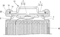
- FIG. 1 is a partially enlarged sectional view of a sealed battery according to the present invention.
- FIG. 2 is a view showing a sealing body used in the sealed battery according to the present invention.
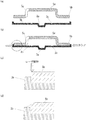
- FIG. 3 is a diagram illustrating a process of welding the terminal cap and the safety valve in the sealed battery according to the present invention.
- FIG. 4 is a partially enlarged cross-sectional view of a sealed battery according to Patent Document 1.
- FIG. 1 is an enlarged cross-sectional view of a main part of a sealed battery according to the present embodiment
- FIG. 2 is a diagram showing a sealing body used in the sealed battery according to the present invention.
- the sealing body 10 via the insulating gasket 30 is arranged in the opening of the outer can 20 that houses the electrode body 40 and the nonaqueous electrolyte.
- the caulking has been fixed.
- the sealing body 10 used in the sealed battery according to the present embodiment includes a terminal plate 1 electrically connected to the positive electrode or the negative electrode via the electrode tab 8, and the outside of the battery.
- the terminal cap 5 having an external terminal portion 5a protruding in the direction, and interposed between the terminal plate 1 and the terminal cap 5 are deformed when the battery internal pressure rises, so that the terminal plate 1 and the terminal cap 5 A safety valve 3 that cuts off the electrical connection and an insulating member 2 that prevents electrical contact between the safety valve 3 and the terminal plate 1 when the safety valve 3 cuts off the current are provided. Then, one electrode of the electrode body 40 and the terminal plate 1 are connected via the electrode tab 8.
- the diameter of the safety valve 3 is larger than the diameter of the terminal cap 5, and the peripheral portion 3 b of the safety valve 3 is bent toward the flange portion 5 b of the terminal cap 5.
- a conductive adhesive portion 9 is formed in which the vicinity is conductively bonded by laser welding.
- the outer periphery of the peripheral part 3b is located inside the battery outer surface of the flange part 5b.
- a part of the external terminal portion 5a of the terminal cap 5 is provided with a gas vent hole 5c for discharging the gas inside the battery to the outside of the battery.
- a positive electrode active material made of lithium cobaltate (LiCoO 2 ), a carbon-based conductive agent such as artificial graphite, and a binder made of polyvinylidene fluoride (PVDF) are in a mass ratio of 85.5: 9.5: 5. These are weighed out and mixed with an organic solvent composed of N-methyl-2-pyrrolidone to prepare a positive electrode active material slurry.
- this positive electrode active material slurry is applied to both surfaces of the positive electrode core made of aluminum foil (thickness: 20 ⁇ m) with a uniform thickness.
- This electrode plate is passed through a dryer to remove the organic solvent, and a dried electrode plate is produced.
- the dried electrode plate is rolled using a roll press and cut.
- the positive electrode current collection tab which consists of aluminum foils is attached by ultrasonic welding, and a positive electrode plate is produced.
- Lithium-containing transition metal composite oxides such as oxides obtained by substituting some of the transition metals contained in the product with other elements, lithium iron phosphate (LiFePO 4 ), etc., alone or in combination of two or more be able to.
- a negative electrode active material made of graphite particles, a binder made of styrene butadiene rubber, and a thickener made of carboxymethyl cellulose are mixed at a mass ratio of 100: 3: 2, and these are mixed with an appropriate amount of water.
- a negative electrode active material slurry is prepared.
- this negative electrode active material slurry is applied to both surfaces of a negative electrode core made of copper foil (thickness: 15 ⁇ m) with a uniform thickness.
- This electrode plate is passed through a dryer to remove moisture, and a dried electrode plate is produced. Then, this dry electrode plate is rolled by a roll press and cut. Then, the negative electrode current collection tab which consists of copper foils is attached by ultrasonic welding, and a negative electrode plate is produced.
- a negative electrode material used in the lithium ion secondary battery according to the present embodiment for example, natural graphite, artificial graphite, carbon black, coke, glassy carbon, carbon fiber, or a carbonaceous material such as a fired body thereof,
- a carbonaceous material such as a fired body thereof
- silicon, silicon alloys, lithium, lithium alloys, and metal oxides capable of occluding and releasing lithium can be used.
- the positive electrode, the negative electrode, and a separator made of a polyethylene microporous film are wound by a winder, and an insulating winding tape is provided to complete a wound electrode body.
- a terminal cap 5 having an external terminal portion 5a protruding outward from the battery, a flange portion 5b located at the periphery of the external terminal portion 5a, and a gas vent hole 5c provided in a shoulder portion of the external terminal portion 5a;
- a safety valve having a current-carrying contact part 3a protruding inward of the battery, a peripheral part 3b located at the periphery of the current-carrying contact part 3a, and a notch 3c provided at the peripheral part 3b so as to surround the current-carrying contact part 3a 3 is produced by a known method such as plastic working.
- the diameter of the safety valve 3 is larger than the diameter of the terminal cap 5, and the outer peripheral edge of the peripheral portion 3b of the safety valve 3 is bent in a direction opposite to the protruding direction of the energizing contact portion 3a.
- a nickel-plated iron plate can be used as the material of the terminal cap, and an aluminum plate can be used as the material of the safety valve.
- the terminal cap 5 is disposed on the upper surface of the safety valve 3, and the flange portion 5b of the terminal cap 5 is fitted into the bent portion of the peripheral edge portion 3b of the safety valve 3 to be temporarily fixed (FIG. 3A). reference). Then, it presses from the left-right direction using a press die, and the safety valve 3 and the terminal cap 5 are crimped, and temporary fixation is made stronger (refer FIG.3 (b)).
- the peripheral edge of the peripheral edge portion 3b of the safety valve 3 may be bent after being aligned with the terminal cap 5 and superimposed.
- the terminal cap material near the caulking fixing portion is irradiated with laser (see FIG. 3C), and the flange portion 5b and the peripheral portion 3b are welded (conductive bonding) (see FIG. 3D). At this time, laser welding is preferably performed over the entire circumference of the caulking fixing portion.
- a conductive adhesive may be used to conductively bond the terminal cap 5 and the safety valve 3 in the vicinity of the caulking fixing portion.
- an aluminum terminal plate 1 is welded to the lower surface of the safety valve 3 via a resin insulating plate 2 to produce a sealing body 10 (see FIG. 2).
- An electrolyte salt is added to a nonaqueous solvent in which ethylene carbonate (EC), propylene carbonate (PC), and diethyl carbonate (DEC) are mixed at a volume ratio of 1: 1: 8 (when converted to 1 atm and 25 ° C.).
- EC ethylene carbonate
- PC propylene carbonate
- DEC diethyl carbonate
- LiPF 6 as a solution is dissolved at a rate of 1.0 M (mol / liter).
- the non-aqueous solvent used in the lithium ion secondary battery according to the present embodiment is not limited to the above combinations, and for example, lithium salts such as ethylene carbonate, propylene carbonate, butylene carbonate, and ⁇ -butyrolactone.
- a low viscosity solvent such as pionitrile, dimethylformamide, sulfolane, methyl formate, ethyl formate, methyl acetate, ethyl acetate, propyl acetate, ethyl propionate.
- the high dielectric constant solvent and the low viscosity solvent can be used as a mixed solvent of two or more.
- LiPF 6 LiN (C 2 F 5 SO 2 ) 2 , LiN (CF 3 SO 2 ) 2 , LiClO 4 or LiBF 4 may be used alone or in combination of two or more as the electrolyte salt. Can be used.
- an aromatic compound such as cyclohexylbenzene or tert-amylbenzene can be added to the electrolytic solution.
- ⁇ Battery assembly> The positive electrode current collector of the electrode body and the bottom of the cylindrical rectangular outer can are welded, and the electrolyte is poured into the outer can, and the terminal plate of the sealing body, the negative electrode current collector, and the electrode tab 8 are interposed. Then, the opening of the outer can is caulked and sealed through a gasket, and the battery according to this embodiment is assembled.
- Example 1 A battery according to Example 1 having a height of 65 mm and a diameter of 18 mm was produced in the same manner as in the above embodiment.
- Comparative Example 1 A battery according to Comparative Example 1 was fabricated in the same manner as in the above embodiment except that the sealing body according to the technique of Patent Document 1 was provided.
- the number of pin-like protrusions and counterbore holes was three.
- the diameter of the counterbore hole was 1.4 mm at the large diameter portion and 1.0 mm at the small diameter portion, and the diameter of the pin-shaped protrusion was 0.9 mm and the height was 0.5 mm.
- Example 1 the safety valve and the terminal cap are welded over the entire outer periphery, and there is no gap between them.
- the safety valve and the terminal cap are welded with the pin-shaped protrusion and the counterbore. This is considered to be due to the fact that there is a gap at the outer peripheral edge only between the holes.
- Example 1 and Comparative Example 1 were charged at a constant current of 1 It (1250 mA) until the voltage reached 4.2 V, and then at a constant voltage of 4.2 V until the current reached 0.02 It (25 mA). Thereafter, the temperature in the bath is put into a thermostat bath that changes from ⁇ 30 ° C. to 70 ° C. in 0.5 hour, and a temperature change cycle in which a change from ⁇ 30 ° C. to 70 ° C. to ⁇ 30 ° C. is one cycle is 400 times. Cycled.
- the resistance value between the safety valve and the terminal cap before and after the test was measured with an AC milliohm high tester (manufactured by Hioki Electric). As a result, the difference between the resistance increase values (the difference between the resistance after the test and the resistance before the test) was almost the same (1 m ⁇ or less).
- a sealed body with a safety valve having excellent conductivity can be realized with high productivity, and thus a sealed battery with excellent current extraction efficiency can be manufactured at low cost. Therefore, the industrial significance is great.
Abstract
Description
有底筒状の外装缶の開口部に封口体をカシメ固定することにより密閉する密閉型電池の製造方法において、電池外方に突出した外部端子部と、前記外部端子部の周縁に位置するフランジ部と、を有する端子キャップと、電池内方に突出した通電接触部と、前記通電接触部の周縁に位置し、外周縁が電池外方に折り曲げられた折り曲げ部が設けられた周辺部と、を有する安全弁と、を準備する準備ステップと、前記安全弁と前記端子キャップとを重ね合わせ、前記折り曲げ部を用いて仮固定する仮固定ステップと、前記折り曲げ部と前記周辺部と、を導電接着する導電接着ステップと、を備えることを特徴とする。 The first aspect of the present invention relating to a method for manufacturing a sealed battery for solving the above-described problems is configured as follows.
In a manufacturing method of a sealed battery that is sealed by caulking and fixing a sealing body to an opening of a bottomed cylindrical outer can, an external terminal projecting outward from the battery, and a flange positioned at the periphery of the external terminal A terminal cap having a portion, a current-carrying contact portion protruding inward of the battery, a peripheral portion provided at a periphery of the current-carrying contact portion, and a bent portion in which an outer peripheral edge is bent outward from the battery, A preparatory step for preparing the safety valve, a temporary fixing step for superimposing the safety valve and the terminal cap, and temporarily fixing using the bent portion, and the bent portion and the peripheral portion are conductively bonded. A conductive bonding step.
有底筒状の外装缶の開口部に封口体をカシメ固定することにより密閉する密閉型電池の製造方法において、電池外方に突出した外部端子部と、前記外部端子部の周縁に位置するフランジ部と、を有する端子キャップと、電池内方に突出した通電接触部と、前記通電接触部の周縁に位置する周辺部と、を有し、前記端子キャップよりも直径が大きい安全弁と、を準備する準備ステップと、前記安全弁と前記端子キャップとを重ね合わせ、前記フランジ部の縁より外側の前記周辺部を前記端子キャップ側に折り曲げて仮固定する仮固定ステップと、折り曲げ部近傍の前記フランジ部と前記周辺部と、を導電接着する導電接着ステップと、を備えることを特徴とする。 The second aspect of the present invention relating to a method for manufacturing a sealed battery for solving the above problems is configured as follows.
In a manufacturing method of a sealed battery that is sealed by caulking and fixing a sealing body to an opening of a bottomed cylindrical outer can, an external terminal projecting outward from the battery, and a flange positioned at the periphery of the external terminal A safety cap having a diameter larger than that of the terminal cap, and a terminal cap having a portion, a current-carrying contact portion protruding inward of the battery, and a peripheral portion located at a periphery of the current-carrying contact portion. A preparatory step for superimposing the safety valve and the terminal cap, and temporarily fixing the peripheral portion outside the flange portion by bending the peripheral portion toward the terminal cap, and the flange portion in the vicinity of the bent portion And a conductive bonding step for conductively bonding the peripheral portion to the peripheral portion.
有底筒状の外装缶の開口部に封口体をカシメ固定することにより密閉した密閉型電池において、前記封口体は、電池外方に突出した外部端子部と、前記外部端子部の周縁に位置するフランジ部と、を有する端子キャップと、前記端子キャップより電池内方に位置し、電池内方に突出した通電接触部と、前記通電接触部の周縁に位置する周辺部と、を有し、前記端子キャップよりも直径が大きい安全弁と、を備え、前記安全弁の周辺部の端部が前記端子キャップのフランジ部側に折り曲げられており、且つ、折り曲げ端部近傍における前記周辺部と前記フランジ部との境界部に、導電接着部が形成されていることを特徴とする。 The present invention relating to a sealed battery for solving the above problems is configured as follows.
In a sealed battery sealed by caulking and fixing a sealing body to an opening of a bottomed cylindrical outer can, the sealing body is positioned at an outer terminal portion protruding outward from the battery and a peripheral edge of the outer terminal portion. A terminal cap having a flange portion, a current-carrying contact portion located inward of the battery from the terminal cap and projecting inward of the battery, and a peripheral portion located in the periphery of the current-carrying contact portion, A safety valve having a diameter larger than that of the terminal cap, and an end portion of the peripheral portion of the safety valve is bent toward the flange portion of the terminal cap, and the peripheral portion and the flange portion in the vicinity of the bent end portion A conductive adhesive portion is formed at the boundary between the first and second portions.
本発明を実施するための形態を、リチウムイオン二次電池に適用した例を用いて、図面を用いて詳細に説明する。図1は、本実施の形態にかかる密閉型電池の要部拡大断面図であり、図2は、本発明にかかる密閉型電池に用いる封口体を示す図である。 (Embodiment 1)
The form for implementing this invention is demonstrated in detail using drawing, using the example applied to the lithium ion secondary battery. FIG. 1 is an enlarged cross-sectional view of a main part of a sealed battery according to the present embodiment, and FIG. 2 is a diagram showing a sealing body used in the sealed battery according to the present invention.
コバルト酸リチウム(LiCoO2)からなる正極活物質と、人造黒鉛等の炭素系導電剤と、ポリビニリデンフルオライド(PVDF)からなる結着剤とを、質量比85.5:9.5:5の割合で量り採り、これらをN-メチル-2-ピロリドンからなる有機溶剤等と混合し、正極活物質スラリーを調製する。 <Preparation of positive electrode>
A positive electrode active material made of lithium cobaltate (LiCoO 2 ), a carbon-based conductive agent such as artificial graphite, and a binder made of polyvinylidene fluoride (PVDF) are in a mass ratio of 85.5: 9.5: 5. These are weighed out and mixed with an organic solvent composed of N-methyl-2-pyrrolidone to prepare a positive electrode active material slurry.
黒鉛粒子からなる負極活物質と、スチレンブタジエンゴムからなる結着剤と、カルボキシメチルセルロースからなる増粘剤とを、質量比100:3:2の割合で混合し、これらを適量の水と混合し、負極活物質スラリーを調製する。 <Production of negative electrode>
A negative electrode active material made of graphite particles, a binder made of styrene butadiene rubber, and a thickener made of carboxymethyl cellulose are mixed at a mass ratio of 100: 3: 2, and these are mixed with an appropriate amount of water. A negative electrode active material slurry is prepared.
上記正極と負極とポリエチレン製微多孔膜からなるセパレータとを、巻き取り機により捲回し、絶縁性の巻き止めテープを設け、巻回電極体を完成させる。 <Production of electrode body>
The positive electrode, the negative electrode, and a separator made of a polyethylene microporous film are wound by a winder, and an insulating winding tape is provided to complete a wound electrode body.
(準備ステップ)
電池外方に突出した外部端子部5aと、外部端子部5aの周縁に位置するフランジ部5bと、外部端子部5aの肩部に設けられたガス抜き孔5cと、を有する端子キャップ5と、電池内方に突出した通電接触部3aと、通電接触部3aの周縁に位置する周辺部3bと、周辺部3bであって通電接触部3aを囲うように設けられたノッチ3cと、を有する安全弁3と、を塑性加工等の公知の方法で作製する。なお、安全弁3の直径は端子キャップ5の直径よりも大きく、安全弁3の周辺部3bの外周縁は、通電接触部3aの突出方向と反対方向に折り曲げられている。また、端子キャップの材料には、例えばニッケルメッキされた鉄板を用いることができ、安全弁の材料には例えばアルミニウム板を用いることができる。 <Preparation of sealing body>
(Preparation step)
A
この後、上記安全弁3の上面に、上記端子キャップ5を配置し、安全弁3の周縁部3bの折り曲げ部の中に、端子キャップ5のフランジ部5bをはめ込んで仮固定する(図3(a)参照)。
この後、プレス金型を用いて左右方向から押圧し、安全弁3と端子キャップ5とをカシメにより仮固定をより強固なものとする(図3(b)参照)。 (Temporary fixing step)
Thereafter, the
Then, it presses from the left-right direction using a press die, and the
カシメ固定部近傍の端子キャップ材料にレーザ照射して(図3(c)参照)、フランジ部5bと周辺部3bとを溶接(導電接着)する(図3(d)参照)。このとき、カシメ固定部全周にわたってレーザ溶接することが好ましい。 (Conductive bonding step)
The terminal cap material near the caulking fixing portion is irradiated with laser (see FIG. 3C), and the
エチレンカーボネート(EC)とプロピレンカーボネート(PC)とジエチルカーボネート(DEC)とを体積比1:1:8の割合(1気圧、25℃と換算した場合における)で混合した非水溶媒に、電解質塩としてのLiPF6を1.0M(モル/リットル)の割合で溶解したものを電解液とする。 <Preparation of electrolyte>
An electrolyte salt is added to a nonaqueous solvent in which ethylene carbonate (EC), propylene carbonate (PC), and diethyl carbonate (DEC) are mixed at a volume ratio of 1: 1: 8 (when converted to 1 atm and 25 ° C.). As an electrolytic solution, LiPF 6 as a solution is dissolved at a rate of 1.0 M (mol / liter).
上記電極体の正極集電体と円筒形角形外装缶の缶底とを溶接し、上記電解液と外装缶内に注液し、封口体の端子板と負極集電体と電極タブ8を介して電気的に接続した後、外装缶の開口部を、ガスケットを介してカシメ加工して封止し、本実施の形態にかかる電池を組み立てる。 <Battery assembly>
The positive electrode current collector of the electrode body and the bottom of the cylindrical rectangular outer can are welded, and the electrolyte is poured into the outer can, and the terminal plate of the sealing body, the negative electrode current collector, and the
上記実施の形態と同様にして、高さ65mm、直径18mmの実施例1に係る電池を作製した。 Example 1
A battery according to Example 1 having a height of 65 mm and a diameter of 18 mm was produced in the same manner as in the above embodiment.
上記特許文献1の技術に係る封口体を備えたこと以外は、上記実施の形態と同様にして比較例1に係る電池を作製した。ここで、ピン状突起及びザグリ穴の数はそれぞれ3個とした。また、ザグリ穴の直径は大径部で1.4mm、小径部で1.0mmとし、ピン状突起の直径は0.9mm、高さは0.5mmとした。 (Comparative Example 1)
A battery according to Comparative Example 1 was fabricated in the same manner as in the above embodiment except that the sealing body according to the technique of Patent Document 1 was provided. Here, the number of pin-like protrusions and counterbore holes was three. The diameter of the counterbore hole was 1.4 mm at the large diameter portion and 1.0 mm at the small diameter portion, and the diameter of the pin-shaped protrusion was 0.9 mm and the height was 0.5 mm.
上記実施例1および比較例1の電池の生産性を、端子キャップと安全弁とを取り付ける工程における、両者の位置決めに要する時間により評価した。この結果、比較例1は実施例1のおよそ2倍の時間を要した。 [Productivity test]
The productivity of the batteries of Example 1 and Comparative Example 1 was evaluated by the time required for positioning them in the process of attaching the terminal cap and the safety valve. As a result, Comparative Example 1 took about twice as long as Example 1.
上記実施例1および比較例1の電池をそれぞれ100個用意し、これらの電池を室温(25℃)雰囲気下、定電流0.1It(125mA)で13時間充電した。このとき、安全弁上への漏液の有無を目視にて確認した。この結果、実施例1の電池には漏液が確認されなかったが、比較例1では100個中3個の電池に漏液が確認された。 [Leakage test]
Each of the batteries of Example 1 and Comparative Example 1 was prepared, and these batteries were charged for 13 hours at a constant current of 0.1 It (125 mA) in a room temperature (25 ° C.) atmosphere. At this time, the presence or absence of liquid leakage on the safety valve was visually confirmed. As a result, no leakage was confirmed in the battery of Example 1, but in Comparative Example 1, leakage was confirmed in 3 out of 100 batteries.
上記実施例1および比較例1の電池を、定電流1It(1250mA)で電圧が4.2Vとなるまで、その後定電圧4.2Vで電流が0.02It(25mA)となるまで充電した。この後、槽内温度が0.5時間で-30℃から70℃に変化する恒温槽内に投入し、-30℃~70℃~-30℃の変化を1サイクルとする温度変化サイクルを400サイクル行った。試験前後の安全弁と端子キャップ間の抵抗値をACミリオームハイテスタ(日置電機製)により測定した。この結果、両者の抵抗上昇値(試験後抵抗と試験前抵抗の差)の差は、ほぼ同等(1mΩ以下)であった。 [Welding reliability test]
The batteries of Example 1 and Comparative Example 1 were charged at a constant current of 1 It (1250 mA) until the voltage reached 4.2 V, and then at a constant voltage of 4.2 V until the current reached 0.02 It (25 mA). Thereafter, the temperature in the bath is put into a thermostat bath that changes from −30 ° C. to 70 ° C. in 0.5 hour, and a temperature change cycle in which a change from −30 ° C. to 70 ° C. to −30 ° C. is one cycle is 400 times. Cycled. The resistance value between the safety valve and the terminal cap before and after the test was measured with an AC milliohm high tester (manufactured by Hioki Electric). As a result, the difference between the resistance increase values (the difference between the resistance after the test and the resistance before the test) was almost the same (1 mΩ or less).
2 絶縁板
3 安全弁
3a 通電接触部
3b 周辺部
3c ノッチ
5 端子キャップ
5a 外部端子部
5b フランジ部
5c ガス抜き孔
8 電極タブ
9 導電接着部
10 封口体
20 外装缶
30 絶縁ガスケット
40 電極体 DESCRIPTION OF SYMBOLS 1
Claims (8)
- 有底筒状の外装缶の開口部に封口体をカシメ固定することにより密閉する密閉型電池の製造方法において、
電池外方に突出した外部端子部と、前記外部端子部の周縁に位置するフランジ部と、を有する端子キャップと、
電池内方に突出した通電接触部と、前記通電接触部の周縁に位置し、外周縁が電池外方に折り曲げられた折り曲げ部が設けられた周辺部と、を有する安全弁と、を準備する準備ステップと、
前記安全弁と前記端子キャップとを重ね合わせ、前記折り曲げ部を用いて仮固定する仮固定ステップと、
前記折り曲げ部と前記周辺部と、を導電接着する導電接着ステップと、
を備えることを特徴とする密閉型電池の製造方法。 In the manufacturing method of the sealed battery that is sealed by caulking and fixing the sealing body to the opening of the bottomed cylindrical outer can,
A terminal cap having an external terminal portion protruding outward from the battery, and a flange portion located at the periphery of the external terminal portion;
Preparation for preparing a safety valve having a current-carrying contact part protruding inward of the battery and a peripheral part provided with a bent part that is located at the periphery of the current-carrying contact part and whose outer peripheral edge is bent outward from the battery Steps,
A temporary fixing step of superimposing the safety valve and the terminal cap and temporarily fixing using the bent portion;
A conductive bonding step of conductively bonding the bent portion and the peripheral portion;
A method for producing a sealed battery, comprising: - 有底筒状の外装缶の開口部に封口体をカシメ固定することにより密閉する密閉型電池の製造方法において、
電池外方に突出した外部端子部と、前記外部端子部の周縁に位置するフランジ部と、を有する端子キャップと、
電池内方に突出した通電接触部と、前記通電接触部の周縁に位置する周辺部と、を有し、前記端子キャップよりも直径が大きい安全弁と、を準備する準備ステップと、
前記安全弁と前記端子キャップとを重ね合わせ、前記フランジ部の縁より外側の前記周辺部を前記端子キャップ側に折り曲げて仮固定する仮固定ステップと、
折り曲げ部近傍の前記フランジ部と前記周辺部と、を導電接着する導電接着ステップと、
を備えることを特徴とする密閉型電池の製造方法。 In the manufacturing method of the sealed battery that is sealed by caulking and fixing the sealing body to the opening of the bottomed cylindrical outer can,
A terminal cap having an external terminal portion protruding outward from the battery, and a flange portion located at the periphery of the external terminal portion;
A preparatory step of preparing a safety valve having a current-carrying contact portion protruding inward of the battery and a peripheral portion located at a periphery of the current-carrying contact portion and having a diameter larger than that of the terminal cap;
A temporary fixing step of superimposing the safety valve and the terminal cap, and temporarily fixing the peripheral portion outside the edge of the flange portion by bending the peripheral portion to the terminal cap side;
A conductive bonding step of conductively bonding the flange portion and the peripheral portion in the vicinity of the bent portion;
A method for producing a sealed battery, comprising: - 請求項1又は2に記載の密閉型電池の製造方法において、
前記導電接着ステップが、前記フランジ部と前記周辺部と、を溶接するステップである、
ことを特徴とする密閉型電池の製造方法。 In the manufacturing method of the sealed battery according to claim 1 or 2,
The conductive bonding step is a step of welding the flange portion and the peripheral portion.
A method for producing a sealed battery, comprising: - 請求項3に記載の密閉型電池の製造方法において、
前記導電接着ステップが、前記フランジ部と前記周辺部とのうち、融点が高い材料側に主としてレーザ光が照射されるようにして溶接するステップである、
ことを特徴とする密閉型電池の製造方法。 In the manufacturing method of the sealed battery according to claim 3,
The conductive bonding step is a step of welding so as to mainly irradiate a laser beam on the material side having a high melting point among the flange portion and the peripheral portion.
A method for producing a sealed battery, comprising: - 請求項3又は4に記載の密閉型電池の製造方法において、
前記導電接着ステップは、前記折り曲げ部近傍の前記フランジ部と前記周辺部との境界全てを溶接するステップである、
ことを特徴とする密閉型電池の製造方法。 In the manufacturing method of the sealed battery according to claim 3 or 4,
The conductive bonding step is a step of welding all the boundaries between the flange portion and the peripheral portion in the vicinity of the bent portion.
A method for producing a sealed battery, comprising: - 請求項1又は2に記載の密閉型電池の製造方法において、
前記導電接着ステップが、導電接着剤を用いて、前記フランジ部と前記周辺部とを導電接着するステップである、
ことを特徴とする密閉型電池の製造方法。 In the manufacturing method of the sealed battery according to claim 1 or 2,
The conductive bonding step is a step of conductively bonding the flange portion and the peripheral portion using a conductive adhesive.
A method for producing a sealed battery, comprising: - 請求項1ないし6のいずれか1項に記載の密閉型電池の製造方法において、
前記周辺部の外周縁が、前記フランジ部の電池外側表面よりも電池内側表面側に位置する、
ことを特徴とする密閉型電池の製造方法。 In the manufacturing method of the sealed battery according to any one of claims 1 to 6,
The outer peripheral edge of the peripheral portion is located closer to the battery inner surface than the battery outer surface of the flange portion.
A method for producing a sealed battery, comprising: - 有底筒状の外装缶の開口部に封口体をカシメ固定することにより密閉した密閉型電池において、
前記封口体は、
電池外方に突出した外部端子部と、前記外部端子部の周縁に位置するフランジ部と、を有する端子キャップと、
前記端子キャップより電池内方に位置し、電池内方に突出した通電接触部と、前記通電接触部の周縁に位置する周辺部と、を有し、前記端子キャップよりも直径が大きい安全弁と、を備え、
前記安全弁の周辺部の端部が前記端子キャップのフランジ部側に折り曲げられており、且つ、折り曲げ端部近傍における前記周辺部と前記フランジ部との境界部に、導電接着部が形成されている、
ことを特徴とする密閉型電池。 In a sealed battery sealed by caulking and fixing a sealing body to the opening of a bottomed cylindrical outer can,
The sealing body is
A terminal cap having an external terminal portion protruding outward from the battery, and a flange portion located at the periphery of the external terminal portion;
A safety valve that is located inward of the battery from the terminal cap and protrudes inward of the battery; and a peripheral portion that is positioned at the periphery of the current supply contact portion; and a safety valve having a larger diameter than the terminal cap; With
An end portion of the peripheral portion of the safety valve is bent toward the flange portion of the terminal cap, and a conductive adhesive portion is formed at a boundary portion between the peripheral portion and the flange portion in the vicinity of the bent end portion. ,
A sealed battery characterized by that.
Priority Applications (3)
| Application Number | Priority Date | Filing Date | Title |
|---|---|---|---|
| JP2013512400A JPWO2012147782A1 (en) | 2011-04-28 | 2012-04-25 | Sealed battery and method for manufacturing the same |
| CN201280020668.1A CN103503194A (en) | 2011-04-28 | 2012-04-25 | Sealed Cell and method for manufacturing same |
| US14/111,134 US20140038005A1 (en) | 2011-04-28 | 2012-04-25 | Sealed cell and method for manufacturing same |
Applications Claiming Priority (2)
| Application Number | Priority Date | Filing Date | Title |
|---|---|---|---|
| JP2011101481 | 2011-04-28 | ||
| JP2011-101481 | 2011-04-28 |
Publications (1)
| Publication Number | Publication Date |
|---|---|
| WO2012147782A1 true WO2012147782A1 (en) | 2012-11-01 |
Family
ID=47072300
Family Applications (1)
| Application Number | Title | Priority Date | Filing Date |
|---|---|---|---|
| PCT/JP2012/061073 WO2012147782A1 (en) | 2011-04-28 | 2012-04-25 | Hermetic battery and method for manufacturing same |
Country Status (4)
| Country | Link |
|---|---|
| US (1) | US20140038005A1 (en) |
| JP (1) | JPWO2012147782A1 (en) |
| CN (1) | CN103503194A (en) |
| WO (1) | WO2012147782A1 (en) |
Cited By (6)
| Publication number | Priority date | Publication date | Assignee | Title |
|---|---|---|---|---|
| KR101670362B1 (en) * | 2014-09-04 | 2016-10-31 | 신흥에스이씨주식회사 | CID assembly for a secondary battery and the battery thereof |
| KR101670364B1 (en) * | 2014-09-04 | 2016-10-31 | 신흥에스이씨주식회사 | Method of manufacturing CID assembly for a secondary battery and CID assembly thereof |
| WO2017163999A1 (en) * | 2016-03-25 | 2017-09-28 | 三洋電機株式会社 | Cylindrical battery |
| WO2019159532A1 (en) * | 2018-02-16 | 2019-08-22 | Fdk株式会社 | Sealing body and battery |
| JP2022529468A (en) * | 2020-02-06 | 2022-06-22 | エルジー エナジー ソリューション リミテッド | How to manufacture a secondary battery and how to manufacture a battery pack containing it |
| JP2022117855A (en) * | 2021-02-01 | 2022-08-12 | プライムプラネットエナジー&ソリューションズ株式会社 | Electrode terminal and secondary battery comprising the same |
Families Citing this family (6)
| Publication number | Priority date | Publication date | Assignee | Title |
|---|---|---|---|---|
| JP6490053B2 (en) * | 2014-03-28 | 2019-03-27 | 三洋電機株式会社 | Cylindrical sealed battery and battery pack |
| KR102194984B1 (en) * | 2014-04-08 | 2020-12-28 | 삼성에스디아이 주식회사 | Rechargeable battery |
| KR102389412B1 (en) * | 2018-11-28 | 2022-04-22 | 주식회사 엘지에너지솔루션 | Secondary battery and method of manufacturing the same |
| JP7157956B2 (en) * | 2018-11-29 | 2022-10-21 | パナソニックIpマネジメント株式会社 | Cylindrical battery and manufacturing method thereof |
| US11799158B2 (en) * | 2020-12-29 | 2023-10-24 | Zhuhai Zhi Li Battery Co., Ltd. | Top plate for laser welded lithium-ion button cell battery |
| DE102022120002A1 (en) | 2022-08-09 | 2024-02-15 | Dr. Ing. H.C. F. Porsche Aktiengesellschaft | Cover of a round cell of a traction battery and method for producing the same |
Citations (8)
| Publication number | Priority date | Publication date | Assignee | Title |
|---|---|---|---|---|
| JPH04132158A (en) * | 1990-09-20 | 1992-05-06 | Hitachi Maxell Ltd | Alkaline storage battery |
| JPH08212994A (en) * | 1995-02-08 | 1996-08-20 | Matsushita Electric Ind Co Ltd | Alkaline storage battery and manufacture thereof |
| JP2001126695A (en) * | 1999-10-28 | 2001-05-11 | Sony Corp | Sealed battery |
| JP2001167740A (en) * | 1999-12-07 | 2001-06-22 | Nec Mobile Energy Kk | Sealed battery |
| WO2001059856A1 (en) * | 2000-02-09 | 2001-08-16 | Ngk Insulators, Ltd. | Lithium secondary cell and method for producing the same |
| JP2009039720A (en) * | 2007-08-06 | 2009-02-26 | Nissan Motor Co Ltd | Method and device for joining different metals |
| JP2010135320A (en) * | 2008-12-08 | 2010-06-17 | Samsung Sdi Co Ltd | Secondary battery |
| JP2010277784A (en) * | 2009-05-27 | 2010-12-09 | Sanyo Electric Co Ltd | Sealed battery and its manufacturing method |
Family Cites Families (4)
| Publication number | Priority date | Publication date | Assignee | Title |
|---|---|---|---|---|
| JP3203623B2 (en) * | 1992-03-06 | 2001-08-27 | ソニー株式会社 | Organic electrolyte battery |
| JP3387118B2 (en) * | 1992-06-12 | 2003-03-17 | ソニー株式会社 | Sealed battery |
| CA2381376C (en) * | 2002-04-10 | 2008-12-02 | E-One Moli Energy (Canada) Limited | Header for rechargeable lithium batteries |
| JP5420219B2 (en) * | 2008-09-30 | 2014-02-19 | 三洋電機株式会社 | Sealed battery and method for manufacturing the same |
-
2012
- 2012-04-25 CN CN201280020668.1A patent/CN103503194A/en active Pending
- 2012-04-25 WO PCT/JP2012/061073 patent/WO2012147782A1/en active Application Filing
- 2012-04-25 JP JP2013512400A patent/JPWO2012147782A1/en active Pending
- 2012-04-25 US US14/111,134 patent/US20140038005A1/en not_active Abandoned
Patent Citations (8)
| Publication number | Priority date | Publication date | Assignee | Title |
|---|---|---|---|---|
| JPH04132158A (en) * | 1990-09-20 | 1992-05-06 | Hitachi Maxell Ltd | Alkaline storage battery |
| JPH08212994A (en) * | 1995-02-08 | 1996-08-20 | Matsushita Electric Ind Co Ltd | Alkaline storage battery and manufacture thereof |
| JP2001126695A (en) * | 1999-10-28 | 2001-05-11 | Sony Corp | Sealed battery |
| JP2001167740A (en) * | 1999-12-07 | 2001-06-22 | Nec Mobile Energy Kk | Sealed battery |
| WO2001059856A1 (en) * | 2000-02-09 | 2001-08-16 | Ngk Insulators, Ltd. | Lithium secondary cell and method for producing the same |
| JP2009039720A (en) * | 2007-08-06 | 2009-02-26 | Nissan Motor Co Ltd | Method and device for joining different metals |
| JP2010135320A (en) * | 2008-12-08 | 2010-06-17 | Samsung Sdi Co Ltd | Secondary battery |
| JP2010277784A (en) * | 2009-05-27 | 2010-12-09 | Sanyo Electric Co Ltd | Sealed battery and its manufacturing method |
Cited By (13)
| Publication number | Priority date | Publication date | Assignee | Title |
|---|---|---|---|---|
| KR101670362B1 (en) * | 2014-09-04 | 2016-10-31 | 신흥에스이씨주식회사 | CID assembly for a secondary battery and the battery thereof |
| KR101670364B1 (en) * | 2014-09-04 | 2016-10-31 | 신흥에스이씨주식회사 | Method of manufacturing CID assembly for a secondary battery and CID assembly thereof |
| US11145942B2 (en) | 2016-03-25 | 2021-10-12 | Sanyo Electric Co., Ltd. | Cylindrical battery |
| JPWO2017163999A1 (en) * | 2016-03-25 | 2019-01-31 | 三洋電機株式会社 | Cylindrical battery |
| WO2017163999A1 (en) * | 2016-03-25 | 2017-09-28 | 三洋電機株式会社 | Cylindrical battery |
| WO2019159532A1 (en) * | 2018-02-16 | 2019-08-22 | Fdk株式会社 | Sealing body and battery |
| JP2019145251A (en) * | 2018-02-16 | 2019-08-29 | Fdk株式会社 | Sealed body and battery |
| JP7093199B2 (en) | 2018-02-16 | 2022-06-29 | Fdk株式会社 | Seal and battery |
| JP2022529468A (en) * | 2020-02-06 | 2022-06-22 | エルジー エナジー ソリューション リミテッド | How to manufacture a secondary battery and how to manufacture a battery pack containing it |
| JP7293563B2 (en) | 2020-02-06 | 2023-06-20 | エルジー エナジー ソリューション リミテッド | Method for manufacturing secondary battery and method for manufacturing battery pack including the same |
| US11757152B2 (en) | 2020-02-06 | 2023-09-12 | Lg Energy Solution, Ltd. | Method for manufacturing secondary battery and method for manufacturing battery pack comprising same |
| JP2022117855A (en) * | 2021-02-01 | 2022-08-12 | プライムプラネットエナジー&ソリューションズ株式会社 | Electrode terminal and secondary battery comprising the same |
| JP7334198B2 (en) | 2021-02-01 | 2023-08-28 | プライムプラネットエナジー&ソリューションズ株式会社 | Electrode terminal and secondary battery provided with the electrode terminal |
Also Published As
| Publication number | Publication date |
|---|---|
| JPWO2012147782A1 (en) | 2014-07-28 |
| CN103503194A (en) | 2014-01-08 |
| US20140038005A1 (en) | 2014-02-06 |
Similar Documents
| Publication | Publication Date | Title |
|---|---|---|
| WO2012147782A1 (en) | Hermetic battery and method for manufacturing same | |
| JP6582605B2 (en) | Non-aqueous electrolyte secondary battery and manufacturing method thereof | |
| EP3101723B1 (en) | Secondary battery and secondary battery production method | |
| JP7006683B2 (en) | Cylindrical battery | |
| JP6208687B2 (en) | Cylindrical secondary battery and manufacturing method thereof | |
| US10601002B2 (en) | Cylindrical battery and method for producing the same | |
| JP5103496B2 (en) | Lithium ion secondary battery | |
| US10263237B2 (en) | Cylindrical battery, and collector member used therefor, and manufacturing method thereof | |
| JP5420219B2 (en) | Sealed battery and method for manufacturing the same | |
| CN108352491B (en) | Nonaqueous electrolyte secondary battery | |
| JP6173729B2 (en) | Battery manufacturing method | |
| JP5173095B2 (en) | Sealed battery | |
| CN111247660A (en) | Cylindrical battery | |
| JP4984359B2 (en) | Sealed battery and its sealing plate | |
| JP2018147574A (en) | Square Lithium Ion Secondary Battery | |
| JP5420315B2 (en) | Sealed battery and method for manufacturing the same | |
| JP2010086781A (en) | Exterior can for nonaqueous electrolyte secondary battery and nonaqueous electrolyte secondary battery using the same, and method for manufacturing the nonaqueous electrolyte secondary battery | |
| JP5420288B2 (en) | Sealed battery | |
| JP2010277785A (en) | Sealed battery and its manufacturing method | |
| WO2020137716A1 (en) | Cylindrical battery | |
| JP2000164197A (en) | Nonaqueous electrolyte secondary battery | |
| JP2020053262A (en) | Battery lead connector and battery module | |
| JP2015060654A (en) | Battery |
Legal Events
| Date | Code | Title | Description |
|---|---|---|---|
| 121 | Ep: the epo has been informed by wipo that ep was designated in this application |
Ref document number: 12777754 Country of ref document: EP Kind code of ref document: A1 |
|
| WWE | Wipo information: entry into national phase |
Ref document number: 14111134 Country of ref document: US |
|
| ENP | Entry into the national phase |
Ref document number: 2013512400 Country of ref document: JP Kind code of ref document: A |
|
| NENP | Non-entry into the national phase |
Ref country code: DE |
|
| 122 | Ep: pct application non-entry in european phase |
Ref document number: 12777754 Country of ref document: EP Kind code of ref document: A1 |