WO2012147440A1 - 印刷装置 - Google Patents
印刷装置 Download PDFInfo
- Publication number
- WO2012147440A1 WO2012147440A1 PCT/JP2012/058130 JP2012058130W WO2012147440A1 WO 2012147440 A1 WO2012147440 A1 WO 2012147440A1 JP 2012058130 W JP2012058130 W JP 2012058130W WO 2012147440 A1 WO2012147440 A1 WO 2012147440A1
- Authority
- WO
- WIPO (PCT)
- Prior art keywords
- input
- time
- detected
- unit
- user
- Prior art date
- Legal status (The legal status is an assumption and is not a legal conclusion. Google has not performed a legal analysis and makes no representation as to the accuracy of the status listed.)
- Ceased
Links
Images





Classifications
-
- B—PERFORMING OPERATIONS; TRANSPORTING
- B41—PRINTING; LINING MACHINES; TYPEWRITERS; STAMPS
- B41J—TYPEWRITERS; SELECTIVE PRINTING MECHANISMS, i.e. MECHANISMS PRINTING OTHERWISE THAN FROM A FORME; CORRECTION OF TYPOGRAPHICAL ERRORS
- B41J3/00—Typewriters or selective printing or marking mechanisms characterised by the purpose for which they are constructed
- B41J3/407—Typewriters or selective printing or marking mechanisms characterised by the purpose for which they are constructed for marking on special material
- B41J3/4075—Tape printers; Label printers
Definitions
- the present invention relates to a printing apparatus having a user interface function that allows a user to perform an input operation interactively.
- JP 2007-25460 A Japanese Patent Laid-Open No. 3-266016 JP-A-8-44520 JP 2005-182313 A JP 2007-79806 A
- the user interface function provides an optimum mode according to the user's operation purpose among a plurality of input screen groups (modes). At this time, the influence of the user's proficiency level on the speed and accuracy of the input operation may change depending on the mode provided by the user interface function.
- the user interface function of the printing apparatus can provide an input mode for the user to input a character to be printed and a setting mode for the user to make various settings.
- the setting mode for example, the font, size, width, style, etc. of the character can be set.
- a user who is not skilled in operating the printing apparatus often takes time to perform key operations for performing various settings in the setting mode, rather than inputting characters in the input mode. That is, the setting mode has a greater influence on the speed and accuracy of the input operation by the user's proficiency than the input mode.
- the influence of the user's proficiency varies depending on the mode, the key operation interval, the switch waiting time, the operation time, and the like vary depending on the mode to be determined. Therefore, there is a possibility that the user's proficiency level cannot be accurately specified by the key operation interval, the switch waiting time, and the operation time.
- An object of the present invention is to provide a printing apparatus capable of accurately specifying the user's proficiency even when the user interface function provides a plurality of modes.
- a printing apparatus is a printing apparatus that includes a display unit capable of displaying a screen that allows a user to perform an input operation, and is provided in the printing apparatus or from an operation unit connected to the printing apparatus.
- An operation detecting means for detecting a user input operation, and an input screen for allowing the user to input a character when the input operation detected by the operation detecting means is a first instruction on the display unit.
- a setting screen for causing the user to set the character format is displayed on the display unit.
- the input operation detected by the operation detection means is a print instruction, the character input to the input screen is set as the setting.
- Printing means for printing in the format set on the screen, and when the setting screen is displayed on the display unit, the input operation detected by the detection means is an input effective for setting the format.
- An operation determination means for determining whether the operation is an operation; and after the second instruction is detected by the operation detection means, from the time when the operation determination means first determines that the input operation is valid.
- a first timing means for measuring an elapsed time until the format confirmation instruction is detected; and after the second instruction is detected by the operation detection means and before the format confirmation instruction is detected.
- a counting means for counting the number of times that the operation determining means has determined that the input operation is valid; and after the format determining instruction is detected by the operation detecting means, the first meter First calculation means for calculating an average execution interval of the effective input operations based on the elapsed time counted by the means and the number of times counted by the counting means, the second display control means, When the second instruction is detected by the operation detection unit, at least the average execution interval detected by the first calculation unit among the plurality of setting screens for setting the format in different procedures. The corresponding setting screen is displayed.
- the input screen is displayed when the first instruction is input, and the setting screen is displayed when the second instruction is input.
- a print instruction is input
- the character input on the input screen is printed in the format set on the setting screen.
- the setting screen is displayed, the elapsed time from the first valid operation for the format setting until the confirmation instruction is detected is counted, and the number of valid operations is counted until the confirmation instruction is detected.
- the average execution interval of valid operations is calculated based on the measured elapsed time and the counted number.
- a setting screen corresponding to the calculated average execution interval is displayed.
- the user's proficiency is based on the format setting operation that easily reflects the user's proficiency level among the character input operation on the input screen and the format setting operation on the setting screen.
- An index value indicating the degree (average execution interval of valid operations) is calculated. Therefore, even when the user interface function provides a plurality of modes (a mode in which an input screen is displayed, a mode in which a setting screen is displayed, and the like), the user's proficiency level can be accurately specified. As a result, the format can be set more easily and accurately by displaying the optimal setting screen according to the user's proficiency level.
- the index value indicating the user's proficiency level is an average execution interval of effective operations during the period in which the user actually performs the format setting operation within the display period of the setting screen. Therefore, for example, the user's proficiency level can be specified more accurately than when the number of effective operations, the effective operation time, and the like are used as a single index value.
- the first display control unit includes at least the first calculation unit among the plurality of input screens for inputting the character in different procedures.
- the input screen corresponding to the detected average execution interval may be displayed.
- the character can be set more easily and accurately by displaying the optimal input screen according to the user's proficiency level.
- a second timing unit that counts a total usage time that is a cumulative total of the power-on period of the printing apparatus, wherein the first display control unit detects the first instruction by the operation detection unit;
- the input screen may be displayed in accordance with the average execution interval detected by the first calculation means and the total use time measured by the second time measurement means. In this case, a more suitable input screen can be displayed based on the average effective operation execution interval and the total usage time of the printing apparatus.
- a second timing unit that counts a total usage time that is a cumulative period during which the power of the printing apparatus is turned on; Based on the total use time counted by the means, the second timing means, and the total printing time counted by the third timing means.
- Second calculating means for calculating a certain total editing time, wherein the first display control means detects the average detected by the first calculating means when the first instruction is detected by the operation detecting means.
- the input screen corresponding to the execution interval and the total editing time calculated by the second calculation means may be displayed. In this case, a more suitable input screen can be displayed based on the average execution interval of valid operations and the total editing time of the user.
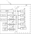
- FIG. 2 is a block diagram showing an electrical configuration of the tape printer 1.
- FIG. It is a screen transition diagram for demonstrating mode transfer. It is a figure which shows the time chart at the time of input operation shown in FIG. It is a flowchart of a count process. It is a flowchart of a proficiency level determination process. It is a flowchart of an apparatus operation process. It is a flowchart of an input operation process. It is a flowchart of a text input process. It is a screen transition diagram for demonstrating text deletion. It is a flowchart of a format setting process.
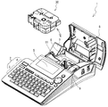
- FIGS. 1 and 2 are respectively the rear side, the front side, the right side, the left side, the upper side, and the tape printer 1. Lower side.
- a keyboard 3 for inputting characters is provided on the upper surface of the tape printer 1.
- a function key group 4 such as a power switch, an application key, and a cursor key is provided on the rear side (upper right side of the drawing) of the keyboard 3.
- the use keys include a print key, a text key, a confirmation key, an Esc key, an all erase key, a cancel key, and the like which will be described later.
- the keyboard 3 and the function key group 4 are collectively referred to as the operation unit 2.
- a display 5 is provided behind the function key group 4.
- a cover 6 that can be opened and closed is provided at the rear of the upper surface of the tape printer 1.
- a tape tray 7 is provided at the left rear corner of the tape printer 1 for receiving a printed tape cut by a cutting mechanism (not shown) described later.
- a cassette mounting portion 8 to which the tape cassette 30 is attached and detached is formed on the rear side of the display 5.
- the tape cassette 30 of the present embodiment accommodates a tape on which characters and the like are printed, an ink ribbon used for printing the tape, and the like inside a cassette case which is a substantially rectangular parallelepiped (box-shaped) housing. Yes.
- the character input by the keyboard 3 is printed using the tape cassette 30 mounted on the cassette mounting unit 8.
- the cassette mounting unit 8 is provided with a tape drive shaft 11 for transporting a tape, a ribbon take-up shaft 9 for taking up a used ink ribbon, a thermal head 10 (see FIG. 3) for printing characters, and the like. ing.
- the thermal head 10 performs printing using an unused ink ribbon on the transported tape.
- a cut mechanism (not shown) for cutting the printed tape is provided on the downstream side of the thermal head 10 in the tape transport direction, which will be described later.
- the tape printer 1 includes a control circuit unit 400 formed on a control board.
- the control circuit unit 400 includes a CPU 401, a ROM 402, a CGROM 403, a RAM 404, a flash memory 410, an input / output interface 411, and the like, which are connected via a data bus.
- the ROM 402 stores various programs that the CPU 401 executes in order to control the tape printer 1.
- the CGROM 403 stores printing dot pattern data for printing characters.
- the RAM 404 is provided with a plurality of storage areas such as a text memory and a print buffer.
- the flash memory 410 stores a time count ⁇ , a key count n, a total usage time Tu, a total printing time Tp, and a proficiency level flag, which will be described later.
- the input / output interface 411 is connected to the operation unit 2, a liquid crystal drive circuit (LCDC) 405, drive circuits 406, 407, 408, and the like.
- the liquid crystal drive circuit (LCDC) 405 has a video RAM (not shown) for outputting display data to the display 5.
- the drive circuit 406 is an electronic circuit for driving the thermal head 10.
- the drive circuit 407 is an electronic circuit for driving the tape feed motor 24 that rotates the ribbon take-up shaft 9 and the tape drive shaft 11.
- the drive circuit 408 is an electronic circuit for driving the cutter motor 25 that operates a cutting mechanism (not shown).
- the tape printer 1 has a user interface function that provides an optimum mode according to the user's operation purpose among a plurality of modes provided in advance for each function and application. In each mode, an optimal input screen group corresponding to the user's operation purpose is sequentially displayed on the display 5. The user can input various information simply and accurately by performing an input operation of the input screen group in each mode in an interactive manner using the operation unit 2.
- the text input mode is executed immediately after the tape printer 1 is turned on.
- an input screen 100 for allowing the user to input text is displayed on the display 5.
- the text indicates one print content composed of characters, and the user can input using the keyboard 3.
- Text input on the input screen 100 is stored in a predetermined storage area of the RAM 404.
- the mode shifts from the text input mode to the formatting mode.
- the text key is a key for instructing transition to the formatting mode.
- a setting screen 200 for allowing the user to set the format is displayed on the display 5.
- the format indicates the display mode (for example, font, size, width, style, underline, arrangement, etc.) of the text printed on the tape, and the user can set it using the operation unit 2.
- a standard format is set in advance, and the user can change the format using a cursor key. Specifically, the user selects an item whose setting content is to be changed with the up and down keys, and changes the setting content of the selected item with the left and right keys.
- the confirmation key is a key for instructing confirmation of contents input or set in the mode being executed.
- the Esc key is a key for instructing to discard the contents input or set in the running mode.
- only the input operation using the cursor key, the confirmation key, and the Esc key is a valid key for the format setting mode. Of these valid keys, an input operation using a cursor key that substantially changes the format is referred to as a format setting valid operation.
- mode shift keys operation keys that cause mode switching, such as the text key, the confirmation key, and the Esc key.
- the processing of the tape printer 1 will be described with reference to FIGS.
- the count process shown in FIG. 6, the device operation process shown in FIG. 8, and the input operation process shown in FIG. 9 are executed in parallel by the CPU 401 when the tape printer 1 is turned on.
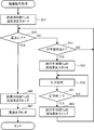
- the counting process for specifying the user's proficiency level will be described.
- the mode transition key When the mode shift key is pressed (S1: YES), it is determined whether or not to shift to the format setting mode (S3).
- S3 When shifting to the format setting mode (S3: YES), the time count ⁇ and the key count n stored in the flash memory 410 are each reset to “0” (S5).
- the time count ⁇ indicates the elapsed time from the first valid operation to formatting in the formatting mode.
- the key count n is the number of effective operations for formatting detected in the formatting mode. Specifically, the elapsed time from the time when the cursor key is first operated in the formatting mode to the time when the enter key is pressed is the time count ⁇ , and the number of times the cursor key is operated in the formatting mode (for example, 5 Times) is the key count n (see FIG. 5).
- step S5 it is determined whether or not the valid key has been pressed (S7).
- the valid key As described above, in the formatting mode, when the cursor key is pressed in any direction, or when the confirmation key or the Esc key is pressed, it is determined that the valid key is pressed (S7: YES). . In this case, it is determined whether or not the time count ⁇ is “0” (S9). When the time count ⁇ is “0” (S9: YES), since the valid key pressed is the first valid operation performed in the format setting mode, the time count ⁇ is started (S11).
- step S11 If the time count ⁇ is not “0” (S9: NO), or after the execution of step S11, it is determined whether or not the pressed valid key is the Esc key (S13). If it is the Esc key (S13: YES), the format set on the setting screen 200 is returned to the state before the start of the format setting mode, and the process returns to step S1. When the Esc key is pressed in the format setting mode, the format setting mode is shifted to the text input mode.
- step S15 If the pressed effective key is not the Esc key (S13: NO), it is determined whether the pressed effective key is a confirmation key (S15). If the valid key that has been pressed is a confirmation key (S15: YES), the format set on the setting screen 200 is confirmed and stored in a predetermined storage area of the flash memory 410. Further, the time count ⁇ is stopped (S17), and the elapsed time from the first valid operation in the format setting mode to the format determination is counted. After execution of step S17, a proficiency level determination process described later is executed (S19), and the process returns to step S1. As described above, when the confirmation key is pressed in the format setting mode, the mode is shifted from the format setting mode to the text input mode.
- step S21 If the pressed effective key is not a confirmation key (S15: NO), the pressed effective key is a cursor key. Accordingly, the key count n is incremented by “1” (S21), and the number of valid operations for formatting is counted. After execution of step S21, the process returns to step S7, and the process according to the type of the valid key is repeatedly executed as described above (S7 to S21).
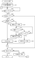
- ⁇ / n is an index value for discriminating the user's proficiency level that indicates the average execution interval of valid operations for formatting performed in the formatting mode. It is determined whether ⁇ / n is smaller than “1” (S33). If ⁇ / n is smaller than “1” (S33: YES), the average execution interval of the valid operations for formatting is relatively small, so it is estimated that the user is an expert who is familiar with the operation of the tape printer 1. can do.
- the total use time Tu is the total of time (use time) when the power of the tape printer 1 is turned on, and a calculation method thereof will be described later.
- the total usage time Tu is less than “10 hours” (S35: NO)
- the total printing time Tp is subtracted from the total usage time Tu stored in the flash memory 410 to calculate the total editing time Te ( S37).
- the total printing time Tp is the total time (printing time) when the printing operation is executed in the tape printer 1, and the calculation method will be described later.
- the total editing time Te is the total time (editing time) during which the user can operate the tape printer 1. It is determined whether or not the total editing time Te is “8 hours” or longer (S39).
- the proficiency level flag stored in the flash memory 410 is set to ON (S41).
- the proficiency level flag is a flag indicating the proficiency level of the user. Specifically, OFF indicates that the user is a beginner, and ON indicates that the user is an expert. Note that the proficiency level flag is set to OFF when the tape printer 1 is initially set.
- step S51 additional measurement of the total usage time Tu stored in the flash memory 410 is started (S51). That is, counting of the total usage time Tu is started from the current cumulative time indicated by the total usage time Tu. After execution of step S51, it is determined whether or not the tape printer 1 is turned off (S53).
- step S55 it is determined whether there is a print instruction (S55). For example, when the user presses the print key, it is determined that there is a print instruction (S55: YES), and additional measurement of the total print time Tp is started (S57). That is, counting of the total printing time Tp is started from the current accumulated time indicated by the total printing time Tp.
- S59 a printing process for printing the text input on the input screen 100 in the format set on the setting screen 200 is executed (S59). Specifically, the text stored in the RAM 404 is printed on the tape in the format stored in the flash memory 410. Thereafter, it is determined whether or not printing has been completed (S61). If the printing is not finished (S61: NO), the process returns to step S59.
- step S63 the additional measurement of the total printing time Tp is stopped (S63), and the total printing time Tp is updated according to the latest printing operation. After execution of step S63, the process returns to step S53.
- the additional measurement of the total usage time Tu is stopped (S65), and the total usage time Tu is updated according to the latest usage status. Further, a power-off process for stabilizing the end state of the tape printer 1 is executed (S67), and the device operation process is ended.
- the execution target mode is a text input mode immediately after the power is turned on, and is a transfer destination mode when the mode shift key is pressed. That is, an instruction to start the execution target mode is input to the CPU 401 by power-on or a mode transition key.
- a text input process described later is executed (S103).
- the execution target mode is not the text input mode (S101: NO)
- the execution target mode is the format setting mode (S105: YES)
- a format setting process described later is executed (S107).
- processing unique to the other execution target modes is executed (S109). After execution of any of steps S103, S107, and S109, the process returns to step S101.
- the text input process (S103) shown in FIG. 10 is a process for executing the text input mode.
- a case where the operation procedure is changed according to the user's proficiency when the user erases all the text input on the input screen 100 will be exemplified. Therefore, of the processes performed when the text input mode is executed, the process related to text erasure will be mainly described.
- the input screen 100 (see FIG. 11) is displayed on the display 5 (S201).
- a valid key in the text input mode for example, a part of the keyboard 3 or the function key group 4
- S203 a valid key in the text input mode
- S205 it is determined whether or not the pressed valid key is a delete all key
- the all erasure key is a key for erasing all characters (that is, text) input on the input screen 100 at once.
- step S211 it is determined whether or not the enter key has been pressed (S213).
- S213: YES the confirmation key is deleted from the display 5 (S215), and the text is deleted from the input screen 100 (S209). If the confirmation key has not been pressed (S213: NO), it is determined whether or not the cancel key has been pressed (S217).
- S217: YES the confirmation message is deleted from the display 5 (S219). If the cancel key has not been pressed (S217: NO), the process returns to step S213. After execution of step S209 or step S219, the process returns to step S203.
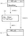
- the delete all key is pressed while the text “broser” is input on the input screen 100.
- the text “broser” is immediately deleted from the input screen 100 (S207: YES, S209).
- a message (confirmation screen 150) for confirming whether or not the text can be deleted is displayed on the display 5 (S207: NO, S211).
- the confirmation key is further pressed, the confirmation screen 150 is deleted, and the text “brother” is deleted from the input screen 100 (S213: YES, S215, S209).
- the confirmation screen 150 is displayed before the text is erased, so that an erroneous operation of the user can be suppressed.
- step S223 a process corresponding to the pressed valid key is executed (S223). For example, when a character is input using the keyboard 3, the input character is displayed on the input screen 100. The text input on the input screen 100 is stored in the RAM 404 as described above. After execution of step S223, the process returns to step S203. If it is a mode transition key (S221: YES), the process returns to the input operation process (FIG. 9).
- the format setting process (S107) shown in FIG. 12 is a process for executing the format setting mode.
- the process related to screen display will be mainly described.
- a normal setting screen and a simple setting screen are prepared in advance. Both the normal setting screen and the simple setting screen have the same appearance (see FIG. 4). However, on the normal setting screen, all items of the format can be freely set and a shortcut function can be executed.
- the shortcut function is a function for inputting a command by omitting menu selection on the screen by performing a specific key operation.
- the simple setting screen only the main items (for example, font, size, style) of the format can be freely set, and the shortcut function cannot be executed.
- the proficiency level flag stored in the flash memory 410 is on (S251).
- S251: NO a simple setting screen is displayed on the display 5 (S253). That is, if the user is a beginner, the format is set on the simple setting screen. Since only the main items are displayed on the simple setting screen, even a beginner can easily set the format. Furthermore, since the shortcut function is turned off, it is possible to suppress setting mistakes due to erroneous operation by the user.
- the normal setting screen is displayed on the display 5 (S255). That is, if the user is an expert, the format is set on the normal setting screen. Since all items are displayed on the normal setting screen, the user can set a format with a higher degree of freedom. Furthermore, since the shortcut function is turned on, the user can set the format more quickly.
- step S253 or step S255 it is determined whether or not the valid key of the format setting mode has been pressed (S257).
- the valid key differs depending on whether the normal setting screen or the simple setting screen is displayed.
- S257: YES it is determined whether or not the pressed valid key is a mode transition key (S259). If it is not a mode transition key (S259: NO), a process corresponding to the pressed valid key is executed (S261). For example, when a format is set using a cursor key, the set format is displayed on the setting screen 200.
- a shortcut operation is performed on the normal setting screen, a command corresponding to the operation is executed.
- step S261 After execution of step S261, the process returns to step S257. If it is a mode transition key (S259: YES), the process returns to the input operation process (FIG. 9). If the mode transition key is a confirmation key, the format set in the setting screen 200 is stored in the flash memory 410 as described above.
- the input screen 100 is displayed.
- a format setting mode start instruction is input, a setting screen 200 is displayed.
- the print key is pressed, the text input on the input screen 100 is printed in the format set on the setting screen 200.
- the setting screen 200 is displayed, the time count ⁇ is counted and the key count n is counted.
- an average execution interval ( ⁇ / n) of valid operations is calculated.
- a setting screen 200 normal setting screen or simple setting screen
- the character input mode an input screen 100 on which a message is displayed when the text is erased or an input screen 100 on which no message is displayed when the text is erased is displayed according to the proficiency level flag.
- the tape printer 1 based on the format setting operation in which the user's skill level is easily reflected between the text input operation on the input screen 100 and the format setting operation on the setting screen 200.
- An index value (average effective operation execution interval) indicating the user's proficiency level is calculated. Therefore, even when the user interface function provides a plurality of modes (text input mode, formatting mode, etc.), the user's proficiency level can be accurately specified.
- the format can be set more easily and accurately by displaying the optimal setting screen 200 according to the user's proficiency level. By displaying the optimal input screen 100 according to the user's proficiency level, it is possible to input text more easily and accurately.
- the index value indicating the proficiency level of the user is an average execution interval ( ⁇ / n) of effective operations during the period when the user actually performed the format setting operation. Therefore, for example, the user's proficiency level can be specified more accurately than when the number of effective operations (key count n) or the effective operation time (time count ⁇ ) is used as a single index value.
- the tape printer 1 corresponds to the “printing apparatus” of the present invention.
- the display 5 corresponds to the “display unit” of the present invention.
- the CPU 401 corresponds to the “operation detection unit” of the present invention.
- the CPU 401 that executes steps S201, S207, and S211 corresponds to the “first display control unit” of the present invention.
- the CPU 401 that executes steps S251 to S255 corresponds to the “second display control means” of the present invention.
- the CPU 401 executing step S59 corresponds to the “printing unit” of the present invention.
- the CPU 401 that executes step S7 corresponds to the “operation determination unit” of the present invention.
- the CPU401 which performs step S11, S17 corresponds to the "first time measuring means" of the present invention.
- the CPU 401 that executes step S21 corresponds to the “counting unit” of the present invention.
- the CPU 401 that executes step S31 corresponds to the “first calculation unit” of the present invention.
- the CPU 401 that executes steps S51 and S65 corresponds to the “second timing unit” of the present invention.
- the CPU 401 executing steps S57 and S63 corresponds to the “third time measuring means” of the present invention.
- the CPU 401 that executes step S37 corresponds to the “second calculation unit” of the present invention.
- the proficiency level flag is set using the total use time Tu and the total edit time Te in addition to the average execution interval ( ⁇ / n).
- the proficiency level flag may be set based only on the average execution interval ( ⁇ / n) by not executing steps S35 to S39.
- the proficiency level flag may be set using at least one of the total usage time Tu, the total editing time Te, and the total printing time Tp.
- the proficiency level flag may be set based on the average execution interval ( ⁇ / n) and the total usage time T.
- a proficiency level flag may be set based on the average execution interval ( ⁇ / n) and the total editing time Te. According to this, it is possible to display a more suitable input screen 100 not only based on the average execution interval ( ⁇ / n) but also based on the total use time Tu, the total edit time Te, the total print time Tp, and the like.
- the input screen 100 and the setting screen 200 differ in items that can be set, shortcut functions, messages, and the like according to the proficiency level flag (that is, the proficiency level of the user).
- the screen displayed according to the proficiency level flag may be any display content, operation method, operation procedure, or the like according to the proficiency level of the user.
- the input screen 100 (or the setting screen 200) having a completely different screen configuration may be displayed depending on whether the user is a beginner or an expert.
- the present invention can be applied to any printing apparatus including a display unit capable of displaying a screen that allows a user to perform an input operation.
- the present invention may be applied to a printing apparatus that prints images or characters on paper.
- the operation unit 2 on which the user performs an input operation may be provided in the tape printer 1 itself, or may be connected from the outside of the tape printer 1.
Landscapes
- Accessory Devices And Overall Control Thereof (AREA)
Abstract
テープ印字装置では、書式設定モードに移行すると、タイムカウントγおよびキーカウントnがリセットされる(S1:YES、S3:YES、S5)。最初の有効キーが押下されるとタイムカウントγがスタートされて(S7:YES、S9:YES、S11)、有効キーの押下に応じてキーカウントnがアップされる(S7:YES、S9:NO、S13:NO、S15:NO、S21)。確定キーが押下されると、タイムカウントγがストップされて、有効操作の平均実行間隔(γ/n)に基づいてユーザの習熟度が判定される(S15:YES、S17、S19)。
Description
本発明は、ユーザに対話形式で入力操作を行わせるユーザインターフェース機能を備えた印刷装置に関する。
従来、ユーザに対話形式で入力操作を行わせるユーザインターフェース機能を備え、ユーザの入力操作に応じて機能設定や印刷処理などを実行する印刷装置が知られている。このような印刷装置において、ユーザの入力操作に応じて習熟度を判断して、習熟度に応じた操作画面を表示する技術が知られている(例えば、特許文献1参照)。具体的に、特許文献1に開示の画像形成装置では、キャンセル操作が行われた回数が所定値を超えた場合には、操作者が不慣れであると判断される。この場合、操作パネルの表示が、通常の操作画面から簡易な操作画面に切り替えられる。
ユーザインターフェース機能を備えた機器において、ユーザの習熟度を判断するための各種手法が提案されている(例えば、特許文献2~5参照)。例えば、キー操作間隔、操作可能状態になってから入力操作が行われるまでの経過時間(スイッチ待ち時間)、操作開始タイミングから要求確定までの経過時間(操作時間)などに基づいて、ユーザの習熟度を判断することが提案されている。
印刷装置の操作に熟練しているユーザでも、例えば印刷装置を急いで操作する場合には、キャンセル操作の頻度が増える。そのため、キャンセル操作の回数では、ユーザの習熟度を正確に特定できないおそれがあった。
一般に、ユーザインターフェース機能は、複数の入力画面群(モード)のうちで、ユーザの操作目的に応じた最適なモードを提供する。このとき、ユーザインターフェース機能が提供するモードに応じて、ユーザの習熟度が入力操作の速さおよび正確さに与える影響が変化することがある。
例えば、印刷装置のユーザインターフェース機能は、ユーザが印刷するキャラクタを入力するための入力モードと、ユーザが各種設定を行うための設定モードとを提供可能である。設定モードでは、例えばキャラクタのフォント、サイズ、幅、スタイルなどを設定可能である。印刷装置の操作に熟練していないユーザは、入力モードにおけるキャラクタの入力操作よりも、設定モードにおける各種設定を行うためのキー操作に手間取ることが多い。つまり、設定モードは、入力モードよりも、ユーザの習熟度が入力操作の速さおよび正確さに与える影響が大きい。
このように、モードに応じてユーザの習熟度が与える影響が異なると、判断対象のモードによってキー操作間隔、スイッチ待ち時間、操作時間などが変化する。したがって、キー操作間隔、スイッチ待ち時間、操作時間では、ユーザの習熟度を正確に特定できないおそれがあった。
本発明の目的は、ユーザインターフェース機能が複数のモードを提供する場合でも、ユーザの習熟度を正確に特定することができる印刷装置を提供することである。
本発明の一態様に係る印刷装置は、ユーザに入力操作させる画面を表示可能な表示部を備えた印刷装置であって、前記印刷装置に備えられ、または前記印刷装置に接続された操作部から、ユーザの入力操作を検出する操作検出手段と、前記操作検出手段によって検出された前記入力操作が第一の指示である場合、ユーザにキャラクタを入力させるための入力用画面を、前記表示部に表示させる第一表示制御手段と、前記操作検出手段によって検出された前記入力操作が第二の指示である場合、ユーザに前記キャラクタの書式を設定させるための設定用画面を、前記表示部に表示させる第二表示制御手段と、前記操作検出手段によって検出された前記入力操作が印刷指示である場合、前記入力用画面に入力された前記キャラクタを、前記設定用画面に設定された前記書式で印刷する印刷手段と、前記表示部に前記設定用画面が表示されている場合に、前記検出手段によって検出される前記入力操作が、前記書式の設定に有効な入力操作であるか否かを判断する操作判断手段と、前記操作検出手段によって前記第二の指示が検出されたのち、前記操作判断手段によって前記有効な入力操作であると最初に判断された時点から、前記書式の確定指示が検出されるまでの経過時間を計時する第一計時手段と、前記操作検出手段によって前記第二の指示が検出されたのち、前記書式の確定指示が検出されるまでに、前記操作判断手段によって前記有効な入力操作であると判断された回数を計数する計数手段と、前記操作検出手段によって前記書式の確定指示が検出されたのちに、前記第一計時手段によって計時された経過時間と、前記計数手段によって計数された回数とに基づいて、前記有効な入力操作の平均実行間隔を算出する第一算出手段とを備え、前記第二表示制御手段は、前記操作検出手段によって前記第二の指示が検出された場合、それぞれ異なる手順で前記書式を設定させる複数の前記設定用画面のうちで、少なくとも前記第一算出手段によって検出された前記平均実行間隔に応じた前記設定用画面を表示させる。
上記印刷装置によれば、第一の指示が入力されると入力用画面が表示され、第二の指示が入力されると設定用画面が表示される。印刷指示が入力されると、入力用画面に入力されたキャラクタが、設定用画面に設定された書式で印刷される。設定用画面の表示中には、書式設定に対する最初の有効操作から確定指示が検出されるまでの経過時間が計時されるとともに、確定指示が検出されるまで有効操作の回数が計数される。書式の確定指示が入力されると、計時された経過時間と、計数された回数とに基づいて、有効操作の平均実行間隔が算出される。第二の指示が入力された場合には、算出された平均実行間隔に応じた設定用画面が表示される。
このように、上記印刷装置では、入力用画面でのキャラクタ入力操作と、設定用画面での書式設定操作とのうちで、ユーザの習熟度が反映されやすい書式設定操作に基づいて、ユーザの習熟度を示す指標値(有効操作の平均実行間隔)が算出される。よって、ユーザインターフェース機能が複数のモード(入力用画面が表示されるモードや、設定用画面が表示されるモードなど)を提供する場合でも、ユーザの習熟度を正確に特定することができる。ひいては、ユーザの習熟度に応じた最適な設定用画面を表示することで、書式をより容易且つ正確に設定することができる。
さらに、ユーザの習熟度を示す指標値は、設定用画面の表示期間のうちで、ユーザが実際に書式の設定操作を行った期間における、有効操作の平均実行間隔である。そのため、例えば有効操作回数や有効操作時間などを単独の指標値として用いる場合と比較して、ユーザの習熟度をより正確に特定することができる。
前記第一表示制御手段は、前記操作検出手段によって前記第一の指示が検出された場合、それぞれ異なる手順で前記キャラクタを入力させる複数の前記入力用画面のうちで、少なくとも前記第一算出手段によって検出された前記平均実行間隔に応じた前記入力用画面を表示させてもよい。この場合、ユーザの習熟度に応じた最適な入力用画面を表示することで、キャラクタをより容易且つ正確に設定することができる。
前記印刷装置の電源が投入されている期間の累計である総使用時間を計時する第二計時手段を備え、前記第一表示制御手段は、前記操作検出手段によって前記第一の指示が検出された場合、前記第一算出手段によって検出された前記平均実行間隔と、前記第二計時手段によって計時された前記総使用時間とに応じた前記入力用画面を表示させてもよい。この場合、有効操作の平均実行間隔と印刷装置の総使用時間とに基づいて、より好適な入力用画面を表示することができる。
前記印刷装置の電源が投入されている期間の累計である総使用時間を計時する第二計時手段と、前記印刷手段によって印刷が行われた期間の累計である総印刷時間を計時する第三計時手段と、前記第二計時手段によって計時された前記総使用時間と、前記第三計時手段によって計時された前記総印刷時間とに基づいて、ユーザが前記操作部で入力操作可能な時間の累計である総編集時間を算出する第二算出手段とを備え、前記第一表示制御手段は、前記操作検出手段によって前記第一の指示が検出された場合、前記第一算出手段によって検出された前記平均実行間隔と、前記第二算出手段によって算出された前記総編集時間とに応じた前記入力用画面を表示させてもよい。この場合、有効操作の平均実行間隔とユーザの総編集時間とに基づいて、より好適な入力用画面を表示することができる。
以下、本発明を具体化した実施の形態について、図面を参照して説明する。なお、参照する図面は、本発明が採用しうる技術的特徴を説明するために用いられるものであり、記載されている装置の構成などは、それのみに限定する趣旨ではなく、単なる説明例である。
図1および図2を参照して、本実施形態に係るテープ印字装置1の概略構成について説明する。本実施形態の説明では、図1および図2の右上側、左下側、右下側、左上側、上側、下側を、それぞれ、テープ印字装置1の後側、前側、右側、左側、上側、下側とする。
図1に示すように、テープ印字装置1の上面には、キャラクタ(文字、記号、数字など)を入力するためのキーボード3が設けられている。キーボード3の後側(紙面右上側)には、電源スイッチ、用途キー、カーソルキー等の機能キー群4が設けられている。用途キーは、後述する印字キー、テキストキー、確定キー、Escキー、全消去キー、キャンセルキーなどを含む。以下の説明では、キーボード3と機能キー群4とを総称する場合、操作部2という。機能キー群4の後側には、ディスプレイ5が設けられている。テープ印字装置1の上面の後部には、開閉可能なカバー6が設けられている。テープ印字装置1の左後角には、後述するカット機構(図示外)によって切断された印字済テープを受けるテープトレイ7が設けられている。
図2に示すように、ディスプレイ5の後側には、テープカセット30が着脱されるカセット装着部8が形成されている。本実施形態のテープカセット30は、略直方体状(箱型)の筐体であるカセットケースの内部に、文字等が印字されるテープや、テープの印字に使用されるインクリボンなどが収容されている。テープ印字装置1では、カセット装着部8に装着されたテープカセット30を用いて、キーボード3で入力されたキャラクタの印字が実行される。
カセット装着部8には、テープを搬送するためのテープ駆動軸11、使用済みのインクリボンを巻き取るためのリボン巻取軸9、キャラクタを印字するサーマルヘッド10(図3参照)などが設けられている。本実施形態では、サーマルヘッド10が、搬送されるテープに未使用のインクリボンを用いて印字を行なう。後述するテープの搬送方向におけるサーマルヘッド10の下流側には、印字済テープを切断するカット機構(図示外)が設けられている。
図3を参照して、テープ印字装置1の電気的構成について説明する。図3に示すように、テープ印字装置1は、制御基板上に形成される制御回路部400を備えている。制御回路部400は、CPU401、ROM402、CGROM403、RAM404、フラッシュメモリ410、入出力インターフェース411などを備え、これらがデータバスを介して接続されている。
ROM402には、CPU401がテープ印字装置1を制御するために実行する各種プログラムが記憶されている。CGROM403には、キャラクタを印字するための印字用ドットパターンデータが記憶されている。RAM404には、テキストメモリ、印字バッファ等、複数の記憶領域が設けられている。フラッシュメモリ410には、後述するタイムカウントγ、キーカウントn、総使用時間Tu、総印字時間Tp、習熟度フラグが記憶されている。
入出力インターフェース411には、操作部2、液晶駆動回路(LCDC)405、駆動回路406、407、408などが接続されている。液晶駆動回路(LCDC)405は、ディスプレイ5に表示データを出力するためのビデオRAM(図示外)を有する。駆動回路406は、サーマルヘッド10を駆動するための電子回路である。駆動回路407は、リボン巻取軸9およびテープ駆動軸11を回転させるテープ送りモータ24を駆動するための電子回路である。駆動回路408は、カット機構(図示外)を動作させるカッターモータ25を駆動するための電子回路である。
図4および図5を参照して、テープ印字装置1の操作態様およびモード移行の一例を説明する。テープ印字装置1は、あらかじめ機能別・用途別に設けられた複数のモードのうち、ユーザの操作目的に応じた最適なモードを提供するユーザインターフェース機能を有する。各モードでは、ユーザの操作目的に応じた最適な入力画面群が、ディスプレイ5に順次表示される。ユーザは、操作部2を用いて各モードの入力画面群を対話形式で入力操作することで、各種情報を簡易且つ正確に入力することができる。
図4および図5に示すように、テープ印字装置1の電源投入直後は、テキスト入力モードが実行される。テキスト入力モードでは、ユーザにテキストを入力させるための入力用画面100がディスプレイ5に表示される。テキストは、キャラクタで構成された一の印字内容を示し、ユーザはキーボード3を用いて入力することができる。入力用画面100で入力されたテキストは、RAM404の所定記憶エリアに記憶される。一方、ユーザがテキスト入力モードでテキストキーを押下すると、テキスト入力モードから書式設定モードに移行する。テキストキーは、書式設定モードへの移行を指示するためのキーである。
書式設定モードでは、ユーザに書式を設定させるための設定用画面200がディスプレイ5に表示される。書式は、テープに印字されるテキストの表示態様(例えば、フォント、サイズ、幅、スタイル、下線、配置など)を示し、ユーザは操作部2を用いて設定することができる。本実施形態の設定用画面200では、あらかじめ標準の書式が設定されており、ユーザはカーソルキーを用いて書式を変更できる。具体的には、ユーザは上下キーで設定内容を変更したい項目を選択し、左右キーで選択項目の設定内容を変更する。
ユーザは、設定用画面200で変更した書式の設定内容を、確定したい場合は確定キーを押下し、破棄したい場合はEscキーを押下する。確定キーは、実行中のモードで入力または設定された内容の確定を指示するためのキーである。Escキーは、実行中のモードで入力または設定された内容の破棄を指示するためのキーである。本実施形態では、カーソルキー、確定キー、Escキーを用いた入力操作のみが、書式設定モードの有効キーである。これらの有効キーのうちで、書式を実体的に変更するカーソルキーを用いた入力操作を、書式設定の有効操作という。
ユーザが書式設定モードで確定キーまたはEscキーを押下すると、書式設定モードからテキスト入力モードに戻る。上記のテキストキー、確定キー、Escキーのように、モードの切り替えが発生する操作キーを、以下では「モード移行キー」という。なお、テキスト入力モードまたは書式設定モードにおいて、ユーザが印字キーを押下すると、入力用画面100で入力されたテキストが、設定用画面200で設定された書式で、テープに印字される。
図6~図12を参照して、テープ印字装置1の処理について説明する。図6に示すカウント処理、図8に示す機器動作処理、図9に示す入力操作処理は、テープ印字装置1が電源オンされたことを契機に、CPU401によって並列的に実行される。
図6を参照して、ユーザの習熟度を特定するためのカウント処理について説明する。図6に示すカウント処理では、まずモード移行キーが押下されたか否かが判断される(S1)。モード移行キーが押下された場合(S1:YES)、書式設定モードに移行するか否かが判断される(S3)。書式設定モードに移行する場合(S3:YES)、フラッシュメモリ410に記憶されているタイムカウントγおよびキーカウントnが、それぞれ「0」にリセットされる(S5)。
タイムカウントγは、書式設定モードにおける最初の有効操作から書式確定までの経過時間を示す。キーカウントnは、書式設定モードで検出された書式設定の有効操作回数である。具体的には、書式設定モードで最初にカーソルキーが操作された時点から確定キーが押下される時点までの経過時間がタイムカウントγであり、書式設定モードにおけるカーソルキーの操作回数(例えば、5回)がキーカウントnである(図5参照)。
ステップS5の実行後、有効キーが押下されたか否かが判断される(S7)。先述のように、書式設定モードでは、カーソルキーがいずれかの方向に押下された場合や、確定キーまたはEscキーが押下された場合に、有効キーが押下されたと判断される(S7:YES)。この場合、タイムカウントγが「0」であるか否かが判断される(S9)。タイムカウントγが「0」である場合(S9:YES)、押下された有効キーは書式設定モードで最初に行われた有効操作であるため、タイムカウントγがスタートされる(S11)。
タイムカウントγが「0」でない場合(S9:NO)、またはステップS11の実行後、押下された有効キーがEscキーであるか否かが判断される(S13)。Escキーである場合(S13:YES)、設定用画面200で設定された書式が書式設定モードの開始前の状態に戻されて、処理はステップS1に戻る。なお、書式設定モードでEscキーが押下された場合には、書式設定モードからテキスト入力モードに移行する。
押下された有効キーがEscキーでない場合(S13:NO)、押下された有効キーが確定キーであるか否かが判断される(S15)。押下された有効キーが確定キーである場合(S15:YES)、設定用画面200で設定された書式が確定されて、フラッシュメモリ410の所定記憶エリアに記憶される。さらに、タイムカウントγがストップされて(S17)、書式設定モードにおける最初の有効操作からの書式確定までの経過時間が計時される。ステップS17の実行後、後述の習熟度判定処理が実行されて(S19)、処理はステップS1に戻る。なお、先述のように、書式設定モードで確定キーが押下された場合には、書式設定モードからテキスト入力モードに移行する。
押下された有効キーが確定キーでない場合(S15:NO)、押下された有効キーはカーソルキーである。よって、キーカウントnが「1」カウントアップされて(S21)、書式設定の有効操作回数がカウントされる。ステップS21の実行後、処理はステップS7に戻り、上述のように有効キーの種別に応じた処理が繰り返し実行される(S7~S21)。
図7に示すように、習熟度判定処理(S19)では、まずタイムカウントγをキーカウントnで除算した値(γ/n)が算出される(S31)。γ/nは、書式設定モードで行われた書式設定の有効操作の平均実行間隔を示す、ユーザの習熟度を判別するための指標値である。γ/nが「1」より小であるか否かが判断される(S33)。γ/nが「1」よりも小である場合(S33:YES)、書式設定の有効操作の平均実行間隔が相対的に小さいため、ユーザをテープ印字装置1の操作に慣れた熟練者と推定することができる。
ところで、ユーザがテープ印字装置1の操作に不慣れな初心者であっても、例えば無意図にカーソルキーを連続押下したり、簡易な書式を設定したりする場合には、書式設定の有効操作の平均実行間隔が小さくなる。よって、本実施形態では、γ/nが「1」よりも小である場合には(S33:YES)、ユーザの習熟度をより正確に特定するために、さらに以下の処理を行う。
すなわち、フラッシュメモリ410に記憶されている総使用時間Tuが、「10時間」以上であるか否かが判断される(S35)。総使用時間Tuは、テープ印字装置1の電源がオンされている時間(使用時間)の累計であり、その算出方法は後述する。総使用時間Tuが「10時間」未満である場合(S35:NO)、フラッシュメモリ410に記憶されている総使用時間Tuから総印字時間Tpが減算されて、総編集時間Teが算出される(S37)。総印字時間Tpは、テープ印字装置1で印字動作が実行された時間(印字時間)の累計であり、その算出方法は後述する。総編集時間Teは、ユーザがテープ印字装置1を操作可能な時間(編集時間)の累計である。総編集時間Teが、「8時間」以上であるか否かが判断される(S39)。
総使用時間Tuが「10時間」以上である場合(S35:YES)、または総編集時間Teが「8時間」以上である場合(S39:YES)、ユーザはテープ印字装置1を使用した経験が豊富であると推定され、ひいてはユーザの習熟度が高いことを推定できる。よって、フラッシュメモリ410に記憶されている習熟度フラグが、オンにセットされる(S41)。習熟度フラグは、ユーザの習熟度を示すフラグであり、詳細には、オフが初心者であることを示し、オンが熟練者であることを示す。なお、テープ印字装置1の初期設定時には、習熟度フラグはオフにセットされている。
一方、γ/nが「1」以上である場合(S33:NO)、書式設定の有効操作の平均実行間隔が相対的に大きいため、ユーザを初心者と推定することができる。γ/nが「1」よりも小であっても、総使用時間Tuが「10時間」未満、且つ総編集時間Teが「8時間」未満である場合(S33:YES、S35:NO、S39:NO)、ユーザはテープ印字装置1を使用した経験が乏しいと推定され、ひいてはユーザの習熟度が低いことを推定できる。よって、これらの場合には、フラッシュメモリ410に記憶されている習熟度フラグが、オフにセットされる(S43)。ステップS41またはステップS43の実行後、処理はカウント処理(図6)に戻る。
図8を参照して、テープ印字装置1の印字動作を制御するための機器動作処理について説明する。図8に示す機器動作処理では、まずフラッシュメモリ410に記憶されている総使用時間Tuの追加測定がスタートされる(S51)。つまり、総使用時間Tuが示す現在の累計時間から、総使用時間Tuのカウントが開始される。ステップS51の実行後、テープ印字装置1が電源オフされたか否かが判断される(S53)。
電源オフされていない場合(S53:NO)、印字指示ありか否かが判断される(S55)。例えばユーザが印字キーを押下した場合、印字指示ありと判断されて(S55:YES)、総印字時間Tpの追加測定がスタートされる(S57)。つまり、総印字時間Tpが示す現在の累計時間から、総印字時間Tpのカウントが開始される。次いで、入力用画面100で入力されたテキストを、設定用画面200で設定された書式で印字する印字処理が実行される(S59)。具体的には、RAM404に記憶されているテキストが、フラッシュメモリ410に記憶されている書式でテープに印字される。その後、印字終了であるか否かが判断される(S61)。印字終了でない場合(S61:NO)、処理はステップS59に戻る。
印字終了である場合(S61:YES)、総印字時間Tpの追加測定がストップされて(S63)、総印字時間Tpが最新の印刷動作に応じて更新される。ステップS63の実行後、処理はステップS53に戻る。電源オフされた場合(S53:YES)、総使用時間Tuの追加測定がストップされて(S65)、総使用時間Tuが最新の使用状況に応じて更新される。さらに、テープ印字装置1の終了状態を安定させるための電源オフ処理が実行されて(S67)、機器動作処理が終了される。
図9を参照して、ユーザの入力操作に応じてテープ印字装置1を制御するための入力操作処理について説明する。図9に示す入力操作処理では、まずテープ印字装置1の実行すべきモード(実行対象モード)が、テキスト入力モードであるか否かが判断される(S101)。実行対象モードは、電源投入直後はテキスト入力モードであり、モード移行キーが押下された場合には移行先のモードである。つまり、電源投入やモード移行キーなどによって、CPU401に対して実行対象モードの開始指示が入力される。
実行対象モードがテキスト入力モードである場合(S101:YES)、後述のテキスト入力処理が実行される(S103)。実行対象モードがテキスト入力モードでない場合(S101:NO)、実行対象モードが書式設定モードであるか否かが判断される(S105)。実行対象モードが書式設定モードである場合(S105:YES)、後述の書式設定処理が実行される(S107)。実行対象モードが書式設定モードでない場合(S105:NO)、その他の実行対象モードに固有の処理が実行される(S109)。ステップS103、S107、S109のいずれかの実行後、処理はステップS101に戻る。
図10に示すテキスト入力処理(S103)は、テキスト入力モードを実行するための処理である。以下の説明では、ユーザが入力用画面100に入力されたテキストを全消去する際に、ユーザの習熟度に応じて操作手順を異ならせる場合を例示する。そのため、テキスト入力モードの実行時に行われる処理のうち、テキストの消去に関する処理を中心に説明する。
まず、入力用画面100(図11参照)がディスプレイ5に表示される(S201)。次いで、テキスト入力モードの有効キー(例えば、キーボード3や機能キー群4の一部)が押下されたか否かが判断される(S203)。有効キーが押下された場合(S203:YES)、押下された有効キーが全消去キーであるか否かが判断される(S205)。全消去キーは、入力用画面100に入力されている全てのキャラクタ(つまり、テキスト)を一括消去するためのキーである。
全消去キーである場合(S205:YES)、フラッシュメモリ410に記憶されている習熟度フラグがオンであるか否かが判断される(S207)。習熟度フラグがオンである場合(S207:YES)、入力用画面100に入力されているテキストが消去されて(S209)、入力用画面100が初期状態に更新される。一方、習熟度フラグがオフである場合(S207:NO)、所定の確認メッセージがディスプレイ5に表示される(S211)。
ステップS211の実行後、確定キーが押下されたか否かが判断される(S213)。確定キーが押下された場合(S213:YES)、ディスプレイ5から確認メッセージが消去され(S215)、さらに入力用画面100からテキストが消去される(S209)。確定キーが押下されなかった場合(S213:NO)、キャンセルキーが押下されたか否かが判断される(S217)。キャンセルキーが押下された場合(S217:YES)、ディスプレイ5から確認メッセージが消去される(S219)。キャンセルキーが押下されなかった場合(S217:NO)、処理はステップS213に戻る。ステップS209またはステップS219の実行後、処理はステップS203に戻る。
具体的には、図11に示すように、入力用画面100にテキスト「brother」が入力された状態で、全消去キーが押下されたと想定する。この場合、ユーザが熟練者であれば、入力用画面100からテキスト「brother」が即座に消去される(S207:YES、S209)。一方、ユーザが初心者であれば、テキストを消去してもよいかを確認するメッセージ(確認画面150)がディスプレイ5に表示される(S207:NO、S211)。さらに確定キーが押下されると、確認画面150が消去され、入力用画面100からテキスト「brother」が消去される(S213:YES、S215、S209)。このように、ユーザが初心者の場合には、テキスト消去前に確認画面150が表示されるので、ユーザの誤操作を抑制することができる。
一方、全消去キーでない場合(S205:NO)、押下された有効キーがモード移行キーであるか否かが判断される(S221)。モード移行キーでない場合(S221:NO)、押下された有効キーに応じた処理が実行される(S223)。例えば、キーボード3を用いてキャラクタが入力された場合は、入力されたキャラクタが入力用画面100に表示される。入力用画面100に入力されているテキストは、先述のようにRAM404に記憶される。ステップS223の実行後、処理はステップS203に戻る。モード移行キーである場合(S221:YES)、処理は入力操作処理(図9)に戻る。
図12に示す書式設定処理(S107)は、書式設定モードを実行するための処理である。以下の説明では、ユーザが書式を設定する際に、ユーザの習熟度に応じて設定用画面200(ひいては、書式設定の操作手順)を異ならせる場合を例示する。そのため、書式設定モードの実行時に行われる処理のうち、画面表示に関する処理を中心に説明する。
本実施形態では、設定用画面200として、通常設定画面および簡易設定画面があらかじめ用意されている。通常設定画面および簡易設定画面は、いずれも外観は同様である(図4参照)。ただし、通常設定画面では、書式の全項目を自由に設定でき、且つショートカット機能を実行可能である。ショートカット機能は、特定のキー操作を行うことで、画面上でのメニュー選択を省略してコマンドを入力する機能である。一方、簡易設定画面では、書式の主要項目(例えば、フォント、サイズ、スタイル)のみを自由に設定でき、且つショートカット機能を実行できない。
まず、フラッシュメモリ410に記憶されている習熟度フラグがオンであるか否かが判断される(S251)。習熟度フラグがオフである場合(S251:NO)、簡易設定画面がディスプレイ5に表示される(S253)。つまり、ユーザが初心者であれば、簡易設定画面で書式を設定させる。簡易設定画面では、主要項目のみが表示されるため、初心者でも容易に書式を設定できる。さらに、ショートカット機能がオフされているので、ユーザの誤操作による設定ミスを抑制できる。
一方、習熟度フラグがオンである場合(S251:YES)、通常設定画面がディスプレイ5に表示される(S255)。つまり、ユーザが熟練者であれば、通常設定画面で書式を設定させる。通常設定画面では、全ての項目が表示されるため、ユーザはより自由度の高い書式を設定できる。さらに、ショートカット機能がオンされているので、ユーザはより迅速に書式を設定できる。
ステップS253またはステップS255の実行後、書式設定モードの有効キーが押下されたか否かが判断される(S257)。ただし、通常設定画面および簡易設定画面のいずれが表示されているかによって、有効キーが異なる。有効キーが押下された場合(S257:YES)、押下された有効キーがモード移行キーであるか否かが判断される(S259)。モード移行キーでない場合(S259:NO)、押下された有効キーに応じた処理が実行される(S261)。例えば、カーソルキーを用いて書式が設定された場合は、設定された書式が設定用画面200に表示される。通常設定画面でショートカット操作が行われた場合には、その操作に応じたコマンドが実行される。
ステップS261の実行後、処理はステップS257に戻る。モード移行キーである場合(S259:YES)、処理は入力操作処理(図9)に戻る。なお、モード移行キーが確定キーである場合は、先述したように、設定用画面200に設定された書式が、フラッシュメモリ410に記憶される。
以上説明したように、本実施形態のテープ印字装置1によれば、テキスト入力モードの開始指示が入力されると、入力用画面100が表示される。書式設定モードの開始指示が入力されると、設定用画面200が表示される。印刷キーが押下されると、入力用画面100に入力されたテキストが、設定用画面200に設定された書式で印刷される。設定用画面200の表示中には、タイムカウントγが計時されるとともに、キーカウントnが計数される。確定キーが押下されると、有効操作の平均実行間隔(γ/n)が算出される。書式設定モードでは、平均実行間隔(γ/n)に応じて設定された習熟度フラグに応じて、設定用画面200(通常設定画面または簡易設定画面)が表示される。キャラクタ入力モードでは、習熟度フラグに応じて、テキスト消去時にメッセージが表示される入力用画面100、またはテキスト消去時にメッセージが表示されない入力用画面100が表示される。
このように、テープ印字装置1では、入力用画面100でのテキスト入力操作と、設定用画面200での書式設定操作とのうちで、ユーザの習熟度が反映されやすい書式設定操作に基づいて、ユーザの習熟度を示す指標値(有効操作の平均実行間隔)が算出される。よって、ユーザインターフェース機能が複数のモード(テキスト入力モードや書式設定モードなど)を提供する場合でも、ユーザの習熟度を正確に特定することができる。ひいては、ユーザの習熟度に応じた最適な設定用画面200を表示することで、書式をより容易且つ正確に設定することができる。ユーザの習熟度に応じた最適な入力用画面100を表示することで、テキストをより容易且つ正確に入力することができる。
さらに、ユーザの習熟度を示す指標値は、ユーザが実際に書式の設定操作を行った期間における、有効操作の平均実行間隔(γ/n)である。そのため、例えば有効操作回数(キーカウントn)や有効操作時間(タイムカウントγ)を単独の指標値として用いる場合と比較して、ユーザの習熟度をより正確に特定することができる。
上記実施形態において、テープ印字装置1が、本発明の「印刷装置」に相当する。ディスプレイ5が、本発明の「表示部」に相当する。CPU401が、本発明の「操作検出手段」に相当する。ステップS201、S207、S211を実行するCPU401が、本発明の「第一表示制御手段」に相当する。ステップS251~S255を実行するCPU401が、本発明の「第二表示制御手段」に相当する。ステップS59を実行するCPU401が、本発明の「印刷手段」に相当する。ステップS7を実行するCPU401が、本発明の「操作判断手段」に相当する。
ステップS11、S17を実行するCPU401が、本発明の「第一計時手段」に相当する。ステップS21を実行するCPU401が、本発明の「計数手段」に相当する。ステップS31を実行するCPU401が、本発明の「第一算出手段」に相当する。ステップS51、S65を実行するCPU401が、本発明の「第二計時手段」に相当する。ステップS57、S63を実行するCPU401が、本発明の「第三計時手段」に相当する。ステップS37を実行するCPU401が、本発明の「第二算出手段」に相当する。
なお、本発明は上記実施形態に限定されるものではなく、種々の変更が可能である。例えば、上記実施形態の習熟度判定処理(図7)では、平均実行間隔(γ/n)と併せて、総使用時間Tuおよび総編集時間Teを用いて習熟度フラグをセットしている。これに代えて、ステップS35~S39を実行しないようにすることで、平均実行間隔(γ/n)のみに基づいて習熟度フラグがセットされてもよい。
平均実行間隔(γ/n)と併せて、総使用時間Tu、総編集時間Te、総印字時間Tpの少なくとも一つを用いて、習熟度フラグをセットしてもよい。例えば、平均実行間隔(γ/n)および総使用時間Tに基づいて、習熟度フラグがセットされてもよい。平均実行間隔(γ/n)および総編集時間Teに基づいて、習熟度フラグがセットされてもよい。これによれば、平均実行間隔(γ/n)のみならず、総使用時間Tu、総編集時間Te、総印字時間Tpなどに基づいて、より好適な入力用画面100を表示することができる。
上記実施形態では、入力用画面100および設定用画面200は、習熟度フラグ(つまり、ユーザの習熟度)に応じて、設定可能な項目、ショートカット機能、メッセージなどが異なっている。ただし、習熟度フラグに応じて表示される画面は、表示内容、操作方法、操作手順などが、ユーザの習熟度に応じたものであればよい。例えば、ユーザが初心者および熟練者のいずれであるかに応じて、画面構成が全く異なる入力用画面100(または設定用画面200)を表示してもよい。
上記実施形態では、本発明をテープ印字装置1に適用した場合を例示したが、本発明はユーザに入力操作させる画面を表示可能な表示部を備えた印刷装置であれば適用できる。例えば、画像や文字などを紙に印刷する印刷装置に、本発明が適用されてもよい。ユーザが入力操作を行う操作部2は、テープ印字装置1自体に備えられてもよいし、テープ印字装置1の外部から接続されてもよい。
Claims (4)
- ユーザに入力操作させる画面を表示可能な表示部(5)を備えた印刷装置(1)であって、
前記印刷装置に備えられ、または前記印刷装置に接続された操作部(2)から、ユーザの入力操作を検出する操作検出手段(401)と、
前記操作検出手段によって検出された前記入力操作が第一の指示である場合、ユーザにキャラクタを入力させるための入力用画面(100)を、前記表示部に表示させる第一表示制御手段(401)と、
前記操作検出手段によって検出された前記入力操作が第二の指示である場合、ユーザに前記キャラクタの書式を設定させるための設定用画面(200)を、前記表示部に表示させる第二表示制御手段(401)と、
前記操作検出手段によって検出された前記入力操作が印刷指示である場合、前記入力用画面に入力された前記キャラクタを、前記設定用画面に設定された前記書式で印刷する印刷手段(401)と、
前記表示部に前記設定用画面が表示されている場合に、前記検出手段によって検出される前記入力操作が、前記書式の設定に有効な入力操作であるか否かを判断する操作判断手段(401)と、
前記操作検出手段によって前記第二の指示が検出されたのち、前記操作判断手段によって前記有効な入力操作であると最初に判断された時点から、前記書式の確定指示が検出されるまでの経過時間を計時する第一計時手段(401)と、
前記操作検出手段によって前記第二の指示が検出されたのち、前記書式の確定指示が検出されるまでに、前記操作判断手段によって前記有効な入力操作であると判断された回数を計数する計数手段(401)と、
前記操作検出手段によって前記書式の確定指示が検出されたのちに、前記第一計時手段によって計時された前記経過時間と、前記計数手段によって計数された前記回数とに基づいて、前記有効な入力操作の平均実行間隔を算出する第一算出手段(401)とを備え、
前記第二表示制御手段は、前記操作検出手段によって前記第二の指示が検出された場合、それぞれ異なる手順で前記書式を設定させる複数の前記設定用画面のうちで、少なくとも前記第一算出手段によって検出された前記平均実行間隔に応じた前記設定用画面を表示させる印刷装置。 - 前記第一表示制御手段は、前記操作検出手段によって前記第一の指示が検出された場合、それぞれ異なる手順で前記キャラクタを入力させる複数の前記入力用画面のうちで、少なくとも前記第一算出手段によって検出された前記平均実行間隔に応じた前記入力用画面を表示させる請求項1に記載の印刷装置。
- 前記印刷装置の電源が投入されている期間の累計である総使用時間を計時する第二計時手段(401)を備え、
前記第一表示制御手段は、前記操作検出手段によって前記第一の指示が検出された場合、前記第一算出手段によって検出された前記平均実行間隔と、前記第二計時手段によって計時された前記総使用時間とに応じた前記入力用画面を表示させる請求項2に記載の印刷装置。 - 前記印刷装置の電源が投入されている期間の累計である総使用時間を計時する第二計時手段(401)と、
前記印刷手段によって印刷が行われた期間の累計である総印刷時間を計時する第三計時手段(401)と、
前記第二計時手段によって計時された前記総使用時間と、前記第三計時手段によって計時された前記総印刷時間とに基づいて、ユーザが前記操作部で入力操作可能な時間の累計である総編集時間を算出する第二算出手段(401)とを備え、
前記第一表示制御手段は、前記操作検出手段によって前記第一の指示が検出された場合、前記第一算出手段によって検出された前記平均実行間隔と、前記第二算出手段によって算出された前記総編集時間とに応じた前記入力用画面を表示させる請求項2に記載の印刷装置。
Applications Claiming Priority (2)
| Application Number | Priority Date | Filing Date | Title |
|---|---|---|---|
| JP2011-099941 | 2011-04-27 | ||
| JP2011099941A JP2012228852A (ja) | 2011-04-27 | 2011-04-27 | 印刷装置 |
Publications (1)
| Publication Number | Publication Date |
|---|---|
| WO2012147440A1 true WO2012147440A1 (ja) | 2012-11-01 |
Family
ID=47071966
Family Applications (1)
| Application Number | Title | Priority Date | Filing Date |
|---|---|---|---|
| PCT/JP2012/058130 Ceased WO2012147440A1 (ja) | 2011-04-27 | 2012-03-28 | 印刷装置 |
Country Status (2)
| Country | Link |
|---|---|
| JP (1) | JP2012228852A (ja) |
| WO (1) | WO2012147440A1 (ja) |
Citations (5)
| Publication number | Priority date | Publication date | Assignee | Title |
|---|---|---|---|---|
| JP2000047532A (ja) * | 1998-07-27 | 2000-02-18 | Canon Inc | 画像形成装置、その表示制御方法、及び記録媒体 |
| JP2001326714A (ja) * | 2000-05-18 | 2001-11-22 | Nec Corp | 情報処理装置および情報処理方法、並びに記録媒体 |
| JP2008204443A (ja) * | 2007-02-19 | 2008-09-04 | Toshiba Corp | 画像処理装置、画像処理装置の操作サポート方法 |
| JP2010176379A (ja) * | 2009-01-29 | 2010-08-12 | Brother Ind Ltd | 印字ラベル作成装置 |
| JP2010198146A (ja) * | 2009-02-24 | 2010-09-09 | Brother Ind Ltd | ステータスモニタプログラム及びこのステータスモニタプログラムを実行するコンピュータ |
-
2011
- 2011-04-27 JP JP2011099941A patent/JP2012228852A/ja not_active Withdrawn
-
2012
- 2012-03-28 WO PCT/JP2012/058130 patent/WO2012147440A1/ja not_active Ceased
Patent Citations (5)
| Publication number | Priority date | Publication date | Assignee | Title |
|---|---|---|---|---|
| JP2000047532A (ja) * | 1998-07-27 | 2000-02-18 | Canon Inc | 画像形成装置、その表示制御方法、及び記録媒体 |
| JP2001326714A (ja) * | 2000-05-18 | 2001-11-22 | Nec Corp | 情報処理装置および情報処理方法、並びに記録媒体 |
| JP2008204443A (ja) * | 2007-02-19 | 2008-09-04 | Toshiba Corp | 画像処理装置、画像処理装置の操作サポート方法 |
| JP2010176379A (ja) * | 2009-01-29 | 2010-08-12 | Brother Ind Ltd | 印字ラベル作成装置 |
| JP2010198146A (ja) * | 2009-02-24 | 2010-09-09 | Brother Ind Ltd | ステータスモニタプログラム及びこのステータスモニタプログラムを実行するコンピュータ |
Also Published As
| Publication number | Publication date |
|---|---|
| JP2012228852A (ja) | 2012-11-22 |
Similar Documents
| Publication | Publication Date | Title |
|---|---|---|
| US10733362B2 (en) | Editing apparatus | |
| US8534941B2 (en) | Expanding a sheet to be cut when an ink dot is present in a cut position | |
| JP5843166B2 (ja) | 印刷装置 | |
| US8894307B2 (en) | Printing apparatus, printing method and computer readable recording medium storing control program for printing apparatus | |
| US20070231043A1 (en) | Label-printing apparatus and label-printing program recorded on a computer readable recording medium | |
| US8767248B2 (en) | Label data processing apparatus and label data processing method | |
| JP2011062985A (ja) | テープ印字装置、テープ印字装置のテープ切断方法及びそのテープ切断方法を実現するためのプログラムが記憶された記憶媒体 | |
| US7474421B2 (en) | Printing apparatus and method of displaying explanations of printing apparatus | |
| JPH10157255A (ja) | 画像作成装置 | |
| JP2010224703A (ja) | 情報処理装置、テープ印刷装置およびプログラム | |
| JP2012228852A (ja) | 印刷装置 | |
| US11813849B2 (en) | Tape printing apparatus, information processing apparatus, method for controlling tape printing apparatus, and storage medium | |
| JP5321898B2 (ja) | テープ印刷装置、ラベルの印刷方法、ラベルの印刷方法のプログラムが記憶された記憶媒体 | |
| JP5109575B2 (ja) | 情報処理装置、テープ印刷装置、情報処理装置の文字列表示方法およびプログラム | |
| US20120041754A1 (en) | Electronic apparatus, method of controlling the electronic apparatus and tape print apparatus | |
| US7625145B2 (en) | Data display method of data display apparatus, data display apparatus, data generation apparatus having the same, and sheet processing apparatus | |
| JP5625828B2 (ja) | 印字装置 | |
| JP2011095970A (ja) | 情報処理装置およびその制御方法 | |
| US10183515B2 (en) | Printing apparatus | |
| US20250042180A1 (en) | Label printer | |
| JP2012159972A (ja) | 印刷システム | |
| JP2012179726A (ja) | テープ印刷装置およびテープ印刷装置の制御方法 | |
| JP3254653B2 (ja) | テープ印刷装置 | |
| JP4572552B2 (ja) | 印刷装置 | |
| JP2023107073A (ja) | 編集方法、プログラム、情報処理装置、及び印刷装置 |
Legal Events
| Date | Code | Title | Description |
|---|---|---|---|
| 121 | Ep: the epo has been informed by wipo that ep was designated in this application |
Ref document number: 12776806 Country of ref document: EP Kind code of ref document: A1 |
|
| NENP | Non-entry into the national phase |
Ref country code: DE |
|
| 122 | Ep: pct application non-entry in european phase |
Ref document number: 12776806 Country of ref document: EP Kind code of ref document: A1 |