WO2012144839A2 - 무선통신시스템에서 장치 대 장치의 신호 전송 방법 및 장치 - Google Patents
무선통신시스템에서 장치 대 장치의 신호 전송 방법 및 장치 Download PDFInfo
- Publication number
- WO2012144839A2 WO2012144839A2 PCT/KR2012/003033 KR2012003033W WO2012144839A2 WO 2012144839 A2 WO2012144839 A2 WO 2012144839A2 KR 2012003033 W KR2012003033 W KR 2012003033W WO 2012144839 A2 WO2012144839 A2 WO 2012144839A2
- Authority
- WO
- WIPO (PCT)
- Prior art keywords
- terminal
- preamble
- transmitted
- base station
- control information
- Prior art date
Links
Images


Classifications
-
- H—ELECTRICITY
- H04—ELECTRIC COMMUNICATION TECHNIQUE
- H04W—WIRELESS COMMUNICATION NETWORKS
- H04W72/00—Local resource management
- H04W72/20—Control channels or signalling for resource management
- H04W72/23—Control channels or signalling for resource management in the downlink direction of a wireless link, i.e. towards a terminal
-
- H—ELECTRICITY
- H04—ELECTRIC COMMUNICATION TECHNIQUE
- H04L—TRANSMISSION OF DIGITAL INFORMATION, e.g. TELEGRAPHIC COMMUNICATION
- H04L5/00—Arrangements affording multiple use of the transmission path
- H04L5/0001—Arrangements for dividing the transmission path
- H04L5/0003—Two-dimensional division
- H04L5/0005—Time-frequency
- H04L5/0007—Time-frequency the frequencies being orthogonal, e.g. OFDM(A), DMT
- H04L5/001—Time-frequency the frequencies being orthogonal, e.g. OFDM(A), DMT the frequencies being arranged in component carriers
-
- H—ELECTRICITY
- H04—ELECTRIC COMMUNICATION TECHNIQUE
- H04L—TRANSMISSION OF DIGITAL INFORMATION, e.g. TELEGRAPHIC COMMUNICATION
- H04L5/00—Arrangements affording multiple use of the transmission path
- H04L5/003—Arrangements for allocating sub-channels of the transmission path
- H04L5/0053—Allocation of signaling, i.e. of overhead other than pilot signals
-
- H—ELECTRICITY
- H04—ELECTRIC COMMUNICATION TECHNIQUE
- H04L—TRANSMISSION OF DIGITAL INFORMATION, e.g. TELEGRAPHIC COMMUNICATION
- H04L5/00—Arrangements affording multiple use of the transmission path
- H04L5/0091—Signaling for the administration of the divided path
-
- H—ELECTRICITY
- H04—ELECTRIC COMMUNICATION TECHNIQUE
- H04W—WIRELESS COMMUNICATION NETWORKS
- H04W56/00—Synchronisation arrangements
- H04W56/004—Synchronisation arrangements compensating for timing error of reception due to propagation delay
- H04W56/0045—Synchronisation arrangements compensating for timing error of reception due to propagation delay compensating for timing error by altering transmission time
-
- H—ELECTRICITY
- H04—ELECTRIC COMMUNICATION TECHNIQUE
- H04L—TRANSMISSION OF DIGITAL INFORMATION, e.g. TELEGRAPHIC COMMUNICATION
- H04L5/00—Arrangements affording multiple use of the transmission path
- H04L5/0001—Arrangements for dividing the transmission path
- H04L5/0014—Three-dimensional division
- H04L5/0023—Time-frequency-space
-
- H—ELECTRICITY
- H04—ELECTRIC COMMUNICATION TECHNIQUE
- H04W—WIRELESS COMMUNICATION NETWORKS
- H04W56/00—Synchronisation arrangements
- H04W56/001—Synchronization between nodes
- H04W56/002—Mutual synchronization
Definitions
- the following description relates to a method for transmitting a device-to-device signal in a wireless communication system and an apparatus therefor.
- Wireless communication systems are widely deployed to provide various kinds of communication services such as voice and data.
- a wireless communication system is a multiple access system capable of supporting communication with multiple users by sharing available system resources (bandwidth, transmission power, etc.).
- multiple access systems include code division multiple access (CDMA) systems, frequency division multiple access (FDMA) systems, time division multiple access (TDMA) systems, orthogonal frequency division multiple access (OFDMA) systems, and single carrier frequency (SC-FDMA).
- CDMA code division multiple access
- FDMA frequency division multiple access
- TDMA time division multiple access
- OFDMA orthogonal frequency division multiple access
- SC-FDMA single carrier frequency division multiple access
- MCD division multiple access
- MCDMA multi-carrier frequency division multiple access
- MC-FDMA multi-carrier frequency division multiple access
- the present invention relates to a method and apparatus for transmitting a device-to-device signal.
- a first technical aspect of the present invention is a method of transmitting a signal to a second terminal by a first terminal in a wireless communication system, the method comprising: requesting a base station to access the second terminal; Receiving control information on the request from the base station; Transmitting a preamble to the second terminal by using the control information; And receiving a response to the preamble transmission from the second terminal, wherein the preamble is transmitted to obtain uplink synchronization of the second terminal.
- a second terminal in a method in which a second terminal receives a signal from a first terminal in a wireless communication system, the first terminal requests the base station to access the second terminal and receives control information; Receiving a preamble transmitted by the terminal; And transmitting a response to the preamble to the first terminal, wherein the preamble is transmitted by the first terminal to obtain uplink synchronization of the second terminal.
- a third technical aspect of the present invention is a base station apparatus in a wireless communication system, comprising: a transmission module; And a processor, wherein the processor receives a connection request from a first terminal to a second terminal and transmits control information for the connection request, wherein the control information is transmitted from the first terminal to the second terminal.
- the preamble is a base station apparatus for the first terminal to obtain the uplink synchronization of the second terminal.
- a fourth technical aspect of the present invention is a terminal device for transmitting a signal to a second terminal in a wireless communication system, comprising: a transmission module; And a processor, wherein the processor requests a base station to access the second terminal, receives control information for the request from the base station, and transmits a preamble to the second terminal using the control information. And receiving a response to the preamble transmission from the second terminal, wherein the preamble is transmitted to obtain uplink synchronization of the second terminal.
- a fifth technical aspect of the present invention is a terminal device for receiving a signal from a first terminal in a wireless communication system, comprising: a receiving module; And a processor, wherein the processor requests a connection to the second terminal from the base station, receives a preamble transmitted by a first terminal receiving control information, and transmits a response to the preamble to the first terminal.
- the preamble is a terminal device in which the first terminal is transmitted to obtain uplink synchronization of the second terminal.
- the first to fifth technical aspects of the present invention may include all of the following.
- the method may further include transmitting an acknowledgment for the response to the second terminal, wherein the first terminal may transmit a preamble for reacquiring uplink synchronization of the second terminal when the acknowledgment is transmitted. have.
- the control information is transmitted on a Physical Downlink Control Channel (PDCCH), and the PDCCH may include downlink control information for instructing the first terminal to transmit the preamble.
- PDCCH Physical Downlink Control Channel
- the downlink control information may include at least one or more of uplink resource allocation, modulation and coding rates, and an identifier of the second terminal.
- the downlink control information further includes a virtual resource block allocation indicator field and a resource block allocation field, wherein the virtual resource block allocation indicator field is set to 0, and the resource block allocation field has the same bit consecutively. It may be.
- the access request may include an identifier of the second terminal.
- the second terminal may receive control information including uplink resource allocation information for the first terminal from the base station.
- the preamble may be a random access preamble.
- the first terminal may transmit data to the second terminal together with the preamble transmission.
- the response may include an acknowledgment for the preamble transmission and a preamble transmitted by the second terminal to obtain uplink synchronization of the first terminal.
- the response may include data transmitted by the second terminal to the first terminal.
- the device-to-device communication can be efficiently operated.
- 1 is a diagram for explaining the structure of a radio frame.
- FIG. 2 is a diagram illustrating a resource grid in a downlink slot.
- 3 is a diagram illustrating a structure of a downlink subframe.
- FIG. 4 is a diagram illustrating a structure of an uplink subframe.
- FIG. 5 is a configuration diagram of a wireless communication system having multiple antennas.
- FIG 6 shows an example of performing backhaul transmission using an MBSFN subframe.
- FIG. 7 is a diagram illustrating an operation process of a terminal and a base station in a contention based random access process.
- FIG. 8 is a diagram for describing carrier aggregation.
- 9 is a diagram for describing cross carrier scheduling.
- FIG. 10 is a diagram for describing a method of transmitting uplink control information through a PUSCH.
- FIG. 11 is a schematic diagram of a D-to-D communication system according to an embodiment of the present invention.
- FIG. 12 is a view for explaining a D-to-D communication procedure according to an embodiment of the present invention.
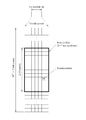
- FIG. 13 is a diagram illustrating PDCCH transmission in D-to-D communication according to an embodiment of the present invention.
- FIG. 14 is a diagram for explaining a D-to-D communication procedure according to an embodiment of the present invention with respect to transmission and reception timing.
- 15 is a diagram for explaining a D-to-D communication procedure according to another embodiment of the present invention.
- 16 is a view for explaining a D-to-D communication procedure between a plurality of terminals according to an embodiment of the present invention.
- 17 is a diagram for explaining downlink control information applied to an embodiment of the present invention.
- FIG. 18 is a diagram illustrating the configuration of a base station apparatus and a terminal apparatus according to an embodiment of the present invention.
- each component or feature may be considered to be optional unless otherwise stated.
- Each component or feature may be embodied in a form that is not combined with other components or features.
- some components and / or features may be combined to form an embodiment of the present invention.
- the order of the operations described in the embodiments of the present invention may be changed. Some components or features of one embodiment may be included in another embodiment or may be replaced with corresponding components or features of another embodiment.
- the base station has a meaning as a terminal node of the network that directly communicates with the terminal.
- the specific operation described as performed by the base station in this document may be performed by an upper node of the base station in some cases.
- a 'base station (BS)' may be replaced by terms such as a fixed station, a Node B, an eNode B (eNB), an access point (AP), and the like.
- Relay can be replaced by terms such as Relay Node (RN), Relay Station (RS).
- terminal may be replaced with terms such as a user equipment (UE), a mobile station (MS), a mobile subscriber station (MSS), a subscriber station (SS), and the like.
- Embodiments of the present invention may be supported by standard documents disclosed in at least one of the wireless access systems IEEE 802 system, 3GPP system, 3GPP LTE and LTE-Advanced (LTE-A) system and 3GPP2 system. That is, steps or parts which are not described to clearly reveal the technical spirit of the present invention among the embodiments of the present invention may be supported by the above documents. In addition, all terms disclosed in the present document can be described by the above standard document.
- CDMA code division multiple access
- FDMA frequency division multiple access
- TDMA time division multiple access
- OFDMA orthogonal frequency division multiple access
- SC-FDMA single carrier frequency division multiple access
- CDMA may be implemented with a radio technology such as Universal Terrestrial Radio Access (UTRA) or CDMA2000.
- TDMA may be implemented with wireless technologies such as Global System for Mobile communications (GSM) / General Packet Radio Service (GPRS) / Enhanced Data Rates for GSM Evolution (EDGE).
- GSM Global System for Mobile communications
- GPRS General Packet Radio Service
- EDGE Enhanced Data Rates for GSM Evolution
- OFDMA may be implemented in a wireless technology such as IEEE 802.11 (Wi-Fi), IEEE 802.16 (WiMAX), IEEE 802-20, Evolved UTRA (E-UTRA).
- UTRA is part of the Universal Mobile Telecommunications System (UMTS).
- 3rd Generation Partnership Project (3GPP) long term evolution (LTE) is part of an Evolved UMTS (E-UMTS) using E-UTRA, and employs OFDMA in downlink and SC-FDMA in uplink.
- LTE-A Advanced
- WiMAX can be described by the IEEE 802.16e standard (WirelessMAN-OFDMA Reference System) and the advanced IEEE 802.16m standard (WirelessMAN-OFDMA Advanced system). For clarity, the following description focuses on 3GPP LTE and 3GPP LTE-A systems, but the technical spirit of the present invention is not limited thereto.
- one radio frame includes 10 subframes, and one subframe includes two slots in the time domain.
- the time for transmitting one subframe is defined as a transmission time interval (TTI).
- TTI transmission time interval
- one subframe may have a length of 1 ms, and one slot may have a length of 0.5 ms.
- One slot may include a plurality of OFDM symbols in the time domain. Since the 3GPP LTE system uses the OFDMA scheme in downlink, the OFDM symbol represents one symbol length. One symbol may be referred to as an SC-FDMA symbol or a symbol length in uplink.
- a resource block (RB) is a resource allocation unit and includes a plurality of consecutive subcarriers in one slot.
- the structure of such a radio frame is merely exemplary. Accordingly, the number of subframes included in one radio frame, the number of slots included in one subframe, or the number of OFDM symbols included in one slot may be changed in various ways.
- Figure 1 (b) illustrates the structure of a type 2 radio frame.
- Type 2 radio frames consist of two half frames. Each half frame consists of five subframes, a Downlink Pilot Time Slot (DwPTS), a Guard Period (GP), and an Uplink Pilot Time Slot (UpPTS), of which one subframe consists of two slots.
- DwPTS is used for initial cell search, synchronization or channel estimation at the terminal.
- UpPTS is used for channel estimation at the base station and synchronization of uplink transmission of the terminal.
- the guard period is a period for removing interference generated in the uplink due to the multipath delay of the downlink signal between the uplink and the downlink.
- the structure of the radio frame is merely an example, and the number of subframes included in the radio frame or the number of slots included in the subframe and the number of symbols included in the slot may be variously changed.
- FIG. 2 is a diagram illustrating a resource grid in a downlink slot.
- One downlink slot includes seven OFDM symbols in the time domain and one resource block (RB) is shown to include 12 subcarriers in the frequency domain, but the present invention is not limited thereto.
- one slot includes 7 OFDM symbols in the case of a general cyclic prefix (CP), but one slot may include 6 OFDM symbols in the case of an extended-CP (CP).
- Each element on the resource grid is called a resource element.
- One resource block includes 12 ⁇ 7 resource elements.
- the number of NDLs of resource blocks included in a downlink slot depends on a downlink transmission bandwidth.
- the structure of the uplink slot may be the same as the structure of the downlink slot.
- FIG. 3 is a diagram illustrating a structure of a downlink subframe.
- Up to three OFDM symbols at the front of the first slot in one subframe correspond to a control region to which a control channel is allocated.
- the remaining OFDM symbols correspond to data regions to which a physical downlink shared channel (PDSCH) is allocated.
- Downlink control channels used in the LTE system include, for example, a physical control format indicator channel (PCFICH), a physical downlink control channel (PDCCH), a physical HARQ indicator channel (PCH).
- PCFICH physical control format indicator channel
- PDCH physical downlink control channel
- PCH physical HARQ indicator channel
- PHICH Physical Hybrid automatic repeat request Indicator Channel
- the PCFICH is transmitted in the first OFDM symbol of a subframe and includes information on the number of OFDM symbols used for control channel transmission in the subframe.
- the PHICH includes a HARQ ACK / NACK signal as a response of uplink transmission.
- the PDCCH transmits downlink control information (DCI).
- the DCI may include uplink or downlink scheduling information or include an uplink transmission power control command for an arbitrary terminal group according to a format.
- DCI formats 0, 1, 1A, 1B, 1C, 1D, 2, 2A, 2B, 2C, 3, 3A, and 4 are defined.
- DCI formats 0, 1A, 3, and 3A are defined to have the same message size in order to reduce the number of blind decoding, which will be described later.
- These DCI formats are i) DCI formats 0, 4, ii) DCI formats 1, 1A, 1B, 1C, 1D, 2, used for downlink scheduling assignment depending on the purpose of the control information to be transmitted. 2A, 2B, 2C, and iii) DCI formats 3 and 3A for power control commands.
- DCI format 0 used for uplink scheduling grant a carrier indicator necessary for carrier aggregation to be described later, an offset used to distinguish DCI formats 0 and 1A (flag for format 0 / format 1A differentiation), A frequency hopping flag indicating whether frequency hopping is used in uplink PUSCH transmission, information on resource block assignment, modulation and coding scheme to be used for PUSCH transmission, and a modulation and coding scheme. ), A new data indicator used to empty the buffer for initial transmission in relation to the HARQ process, a TPC command for scheduled for PUSCH, and a cycle for demodulation reference signal (DMRS).
- DMRS demodulation reference signal
- DCI format 0 uses synchronous HARQ, it does not include a redundancy version like DCI formats related to downlink scheduling allocation. In the case of carrier offset, if cross carrier scheduling is not used, it is not included in the DCI format.
- DCI format 4 is new in LTE-A Release 10 and is intended to support spatial multiplexing for uplink transmission in LTE-A.
- the DCI format 4 further includes information for spatial multiplexing as compared to the DCI format 0, and thus has a larger message size, and further includes additional control information in the control information included in the DCI format 0. That is, the DCI format 4 further includes a modulation and coding scheme for the second transport block, precoding information for multi-antenna transmission, and sounding reference signal request (SRS request) information.
- SRS request sounding reference signal request
- DCI formats 1, 1A, 1B, 1C, 1D, 2, 2A, 2B, and 2C related to downlink scheduling allocation do not significantly support spatial multiplexing, but 1, 1A, 1B, 1C, 1D and 2, which support spatial multiplexing, It can be divided into 2A, 2B, and 2C.
- DCI format 1C supports only frequency continuous allocation as a compact downlink allocation and does not include a carrier offset and a redundant version as compared to other formats.
- DCI format 1A is a format for downlink scheduling and random access procedures. This includes an indicator indicating whether carrier offset, downlink distributed transmission is used, PDSCH resource allocation information, modulation and coding scheme, redundancy version, HARQ processor number to inform processor used for soft combining, HARQ
- the process may include a new data offset used to empty the buffer for initial transmission, a transmit power control command for PUCCH, and an uplink index required for TDD operation.
- DCI format 1 In the case of DCI format 1, most of the control information is similar to DCI format 1A. However, compared to DCI format 1A related to continuous resource allocation, DCI format 1 supports non-contiguous resource allocation. Therefore, DCI format 1 further includes a resource allocation header, so that control signaling overhead is somewhat increased as a trade-off of increasing flexibility of resource allocation.
- DCI formats 1B and 1D are common in that precoding information is further included as compared with DCI format 1.
- DCI format 1B includes PMI verification and DCI format 1D includes downlink power offset information.
- the control information included in the DCI formats 1B and 1D is mostly identical to that of the DCI format 1A.
- the DCI formats 2, 2A, 2B, and 2C basically include most of the control information included in the DCI format 1A, and further include information for spatial multiplexing. This includes the modulation and coding scheme, the new data offset, and the redundancy version for the second transport block.
- DCI format 2 supports closed-loop spatial multiplexing, while 2A supports open-loop spatial multiplexing. Both contain precoding information.
- DCI format 2B supports dual layer spatial multiplexing combined with beamforming and further includes cyclic shift information for DMRS.
- DCI format 2C can be understood as an extension of DCI format 2B and supports public multiplexing up to eight layers.
- DCI formats 3 and 3A may be used to supplement transmission power control information included in DCI formats for uplink scheduling grant and downlink scheduling assignment, that is, to support semi-persistent scheduling. .
- DCI format 3 1 bit per terminal and 2 bit in 3A are used.
- Any one of the above-described DCI formats may be transmitted through one PDCCH, and a plurality of PDCCHs may be transmitted in a control region.
- the terminal may monitor the plurality of PDCCHs.
- a Cyclic Redundancy Check (CRC) is attached to the DCI, and in this process, a radio network temporary identifier (RNTI) is masked.
- the RNTI may use different RNTIs according to the purpose of transmitting the DCI.
- the P-RNTI is used for a paging message related to network initiated connection establishment
- the RA-RNTI is used for random access
- the SI-RNTI is used for a system information block (SIB). Can be.
- SIB system information block
- C-RNTI which is a unique terminal identifier, may be used.
- DCI with CRC is coded with a predetermined code and then adjusted to the amount of resources used for transmission via rate-matching.
- a control channel element which is a continuous logical allocation unit, is used when mapping the PDCCH to REs for efficient processing.
- the CCE consists of 36 REs, which corresponds to 9 units in a resource element group (REG).
- the number of CCEs required for a specific PDCCH depends on the DCI payload, cell bandwidth, channel coding rate, etc., which are the size of control information. In more detail, the number of CCEs for a specific PDCCH may be defined according to the PDCCH format as shown in Table 1 below.
- the transmitter may use the PDCCH format 0 and then adaptively use the PDCCH format by changing the PDCCH format to 2 when the channel condition worsens. have.
- the PDCCH may use any one of four formats, which is not known to the UE. Therefore, the UE needs to decode without knowing the PDCCH format, which is called blind decoding. However, since it is a heavy burden for the UE to decode all possible CCEs used for downlink for each PDCCH format, a search space is defined in consideration of the scheduler limitation and the number of decoding attempts.
- the search space is a set of candidate PDCCHs consisting of CCEs that the UE should attempt to decode on an aggregation level.
- the aggregation level and the number of PDCCH candidates may be defined as shown in Table 2 below.
- the terminal since four aggregation levels exist, the terminal has a plurality of search spaces according to each aggregation level.
- the search space may be divided into a terminal specific search space and a common search space.
- the UE-specific discovery space is for specific UEs, and each UE monitors the UE-specific discovery space (attempting to decode a PDCCH candidate set according to a possible DCI format) to check the RNTI and CRC masked on the PDCCH. Control information can be obtained.
- the common search space is for a case where a plurality of terminals or all terminals need to receive the PDCCH, such as dynamic scheduling or paging message for system information.
- the common search space may be used for a specific terminal for resource management.
- the common search space may overlap with the terminal specific search space.
- the uplink subframe may be divided into a control region and a data region in the frequency domain.
- a physical uplink control channel (PUCCH) including uplink control information is allocated to the control region.
- a physical uplink shared channel (PUSCH) including user data is allocated.
- PUCCH physical uplink control channel
- PUSCH physical uplink shared channel
- one UE does not simultaneously transmit a PUCCH and a PUSCH.
- PUCCH for one UE is allocated to an RB pair in a subframe. Resource blocks belonging to a resource block pair occupy different subcarriers for two slots. This is called a resource block pair allocated to the PUCCH is frequency-hopped at the slot boundary.
- MIMO Multi Input Multi output
- FIG. 5 is a configuration diagram of a wireless communication system having multiple antennas.
- a transmission rate four times higher than a single antenna system may be theoretically obtained.
- the communication method in a multi-antenna system will be described in more detail using mathematical modeling. It is assumed that there are NT transmit antennas and NR receive antennas in the system.
- the transmission signal when there are NT transmit antennas, the maximum information that can be transmitted is NT.
- the transmission information may be expressed as follows.
- Each transmission information The transmit power may be different.
- Each transmit power In this case, the transmission information whose transmission power is adjusted may be expressed as follows.
- Weighting matrix Plays a role in properly distributing transmission information to each antenna according to a transmission channel situation.
- Vector It can be expressed as follows.
- Received signal is received signal of each antenna when there are NR receiving antennas Can be expressed as a vector as
- channels may be divided according to transmit / receive antenna indexes. From the transmit antenna j to the channel through the receive antenna i It is indicated by. Note that in the order of the index, the receiving antenna index is first, and the index of the transmitting antenna is later.
- FIG. 5B is a diagram illustrating a channel from NT transmit antennas to receive antenna i.
- the channels may be bundled and displayed in vector and matrix form.
- a channel arriving from a total of NT transmit antennas to a receive antenna i may be represented as follows.
- AWGN Additive White Gaussian Noise
- the received signal may be expressed as follows.
- the channel matrix indicating the channel state The number of rows and columns of is determined by the number of transmit and receive antennas.
- Channel matrix The number of rows is equal to the number of receive antennas NR, and the number of columns is equal to the number NT of transmit antennas. That is, the channel matrix The matrix is NR x NT.
- the rank of a matrix is defined as the minimum number of rows or columns that are independent of each other. Thus, the rank of the matrix cannot be greater than the number of rows or columns.
- Channel matrix Rank of ( ) Is limited to
- rank may be defined as the number of nonzero eigenvalues when the matrix is eigenvalue decomposition.
- another definition of rank may be defined as the number of nonzero singular values when singular value decomposition is performed. Therefore, the physical meaning of rank in the channel matrix is the maximum number that can send different information in a given channel.
- the UE may perform a random access process in the following cases.
- uplink data When uplink data is not synchronized, or when uplink data is generated in a situation where a designated radio resource used for requesting a radio resource is not allocated.
- FIG. 7 is a diagram illustrating an operation process of a terminal and a base station in a contention based random access process.
- a UE randomly selects one random access preamble from a set of random access preambles indicated by system information or a handover command, and transmits the random access preamble (PRACH).
- the resource may be selected and transmitted (S801).
- the terminal After transmitting the random access preamble as in step S801, the terminal attempts to receive its random access response within the random access response receiving window indicated by the system information or the handover command (S802).
- the random access response information may be transmitted in the form of a MAC PDU, and the MAC PDU may be transmitted through a physical downlink shared channel (PDSCH).
- PDSCH physical downlink shared channel
- the UE monitors a physical downlink control channel (PDCCH). That is, the PDCCH preferably includes information of a terminal that should receive the PDSCH, frequency and time information of radio resources of the PDSCH, a transmission format of the PDSCH, and the like.
- the UE After the UE succeeds in receiving the PDCCH transmitted to the UE, it can properly receive the random access response transmitted to the PDSCH according to the information of the PDCCH.
- the random access response includes a random access preamble identifier (ID), for example, a random access preamble identifier (RAPID), an uplink grant indicating an uplink radio resource (UL grant), and a temporary cell identifier (Temporary C-RNTI).
- ID random access preamble identifier
- RAPID random access preamble identifier
- UL grant uplink radio resource
- Temporal C-RNTI temporary cell identifier
- TACs timing synchronization commands
- the reason why the random access (or random access) preamble discriminator is needed in the random access response is that the UL grant may be included because one random access response may include random access response information for one or more terminals. This is because it is necessary to inform which UE the temporary cell identifier and the TAC are valid. In this step, it is assumed that the UE selects a random access preamble identifier that matches the random access preamble selected by the UE in step S802. Through this, the UE may receive an UL grant, a temporary C-RNTI, a timing synchronization command (TAC), and the like.
- TAC timing synchronization command
- the terminal When the terminal receives a valid random access response to the terminal, it processes each of the information included in the random access response. That is, the terminal applies the TAC and stores the temporary cell identifier.
- the data to be transmitted may be stored in the message 3 buffer in response to receiving a valid random access response.
- the terminal transmits data (ie, a third message) to the base station by using the received UL grant (S803).
- the third message should include the identifier of the terminal.
- the base station cannot determine which terminals perform the random access process, because the terminal needs to be identified for future collision resolution.
- Two methods have been discussed as a method of including the identifier of the terminal.
- the first method if the UE already has a valid cell identifier assigned to the cell before the random access procedure, the UE transmits its cell identifier through an uplink transmission signal corresponding to the UL grant.
- the terminal transmits its own unique identifier (eg, S-TMSI or random ID). In general, the unique identifier is longer than the cell identifier.
- the UE transmits data corresponding to the UL grant it starts a timer for contention resolution (hereinafter referred to as "CR timer").
- the UE After the UE transmits data including its identifier through the UL grant included in the random access response, it waits for an instruction of the base station to resolve the collision. That is, an attempt is made to receive a PDCCH in order to receive a specific message (S804). Two methods have been discussed in the method of receiving the PDCCH. As mentioned above, when the third message transmitted in response to the UL grant is transmitted using a cell identifier of its own, it attempts to receive the PDCCH using its cell identifier, and the identifier is a unique identifier. In this case, it may attempt to receive the PDCCH using the temporary cell identifier included in the random access response.
- the terminal determines that the random access procedure has been normally performed, and terminates the random access procedure.
- the terminal determines that the random access procedure has been normally performed, and terminates the random access procedure.
- the terminal determines that the random access procedure has been normally performed, and ends the random access procedure.
- the operation in the non-competition-based random access process ends the random access procedure only by transmitting the first message and transmitting the second message.
- the terminal before the terminal transmits the random access preamble to the base station as the first message, the terminal is allocated a random access preamble from the base station, and transmits the allocated random access preamble to the base station as the first message, and the random access response from the base station.
- the random access procedure is terminated by receiving.
- a cell may be understood as a combination of downlink resources and uplink resources.
- the uplink resource is not an essential element, and thus, the cell may be composed of only the downlink resource or the downlink resource and the uplink resource.
- the downlink resource may be referred to as a downlink component carrier (DL CC) and the uplink resource may be referred to as an uplink component carrier (UL CC).
- the DL CC and the UL CC may be represented by a carrier frequency, and the carrier frequency means a center frequency in a corresponding cell.
- a cell may be classified into a primary cell (PCell) operating at a primary frequency and a secondary cell (SCell) operating at a secondary frequency.
- PCell and SCell may be collectively referred to as a serving cell.
- the terminal may perform an initial connection establishment (initial connection establishment) process, or the cell indicated in the connection reset process or handover process may be a PCell. That is, the PCell may be understood as a cell that is the center of control in a carrier aggregation environment to be described later.
- the UE may receive and transmit a PUCCH in its PCell.
- the SCell is configurable after the Radio Resource Control (RRC) connection is established and can be used to provide additional radio resources.
- RRC Radio Resource Control
- the remaining serving cells except the PCell may be viewed as SCells.
- the UE In the RRC_CONNECTED state, but the UE is not configured carrier aggregation or does not support carrier aggregation, there is only one serving cell consisting of a PCell.
- the network may configure one or more SCells in addition to the PCell initially configured in the connection establishment process.
- Carrier aggregation is a technology introduced to use a wider band in order to meet the demand for high speed data rates.
- Carrier aggregation may be defined as an aggregation of two or more component carriers (CCs) having different carrier frequencies.
- FIG. 8 (a) shows a subframe when one CC is used in an existing LTE system
- FIG. 8 (b) shows a subframe when carrier aggregation is used.
- FIG. 8B three CCs of 20 MHz are used to support a total bandwidth of 60 MHz.
- each CC may be continuous or may be non-continuous.
- the terminal may simultaneously receive and monitor downlink data through a plurality of DL CCs.
- the linkage between each DL CC and UL CC may be indicated by system information.
- the DL CC / UL CC link may be fixed in the system or configured semi-statically.
- the frequency band that a specific UE can monitor / receive may be limited to M ( ⁇ N) CCs.
- Various parameters for carrier aggregation may be set in a cell-specific, UE group-specific, or UE-specific manner.
- Cross-carrier scheduling means, for example, including all downlink scheduling allocation information of another DL CC in a control region of one DL CC among a plurality of serving cells, or a DL CC of any one of a plurality of serving cells. This means that the control region includes all uplink scheduling grant information for the plurality of UL CCs linked with the DL CC.
- the CIF may be included or not included in the DCI format transmitted through the PDCCH, and when included, it indicates that the cross carrier scheduling is applied.
- cross carrier scheduling is not applied, downlink scheduling allocation information is valid on a DL CC through which current downlink scheduling allocation information is transmitted.
- the uplink scheduling grant is also valid for one UL CC linked with the DL CC through which the downlink scheduling assignment information is transmitted.
- the CIF indicates a CC related to downlink scheduling allocation information transmitted through a PDCCH in one DL CC.
- downlink allocation information about DL CC B and DL CC C that is, information about PDSCH resources, is transmitted through a PDCCH in a control region on DL CC A.
- the UE monitors the DL CC A to know the resource region of the PDSCH and the corresponding CC through the CIF.
- CIF is included or not included in the PDCCH may be set semi-statically and may be UE-specific activated by higher layer signaling.
- the PDCCH on a particular DL CC may allocate PDSCH resources on that same DL CC and allocate PUSCH resources on a UL CC linked to the particular DL CC.
- the same coding scheme, CCE-based resource mapping, DCI format, and the like as the existing PDCCH structure may be applied.
- the PDCCH on a specific DL CC may allocate PDSCH / PUSCH resources on one DL / UL CC indicated by the CIF among a plurality of merged CCs.
- the CIF may be additionally defined in the existing PDCCH DCI format, may be defined as a fixed 3-bit field, or the CIF position may be fixed regardless of the DCI format size.
- the same coding scheme, CCE-based resource mapping, DCI format, and the like as the existing PDCCH structure may be applied.
- the base station can allocate a set of DL CC to monitor the PDCCH. Accordingly, the burden of blind decoding of the terminal can be reduced.
- the PDCCH monitoring CC set is a part of the total merged DL CCs and the UE may perform detection / decoding of the PDCCH only in the corresponding CC set. That is, in order to schedule PDSCH / PUSCH for the UE, the base station may transmit the PDCCH only on the PDCCH monitoring CC set.
- the PDCCH monitoring DL CC set may be configured as UE-specific or UE group-specific or cell-specific. For example, when three DL CCs are merged as in the example of FIG.
- DL CC A may be set to the PDCCH monitoring DL CC.
- the PDCCH on each DL CC may only schedule PDSCH in DL CC A.
- the PDCCH on DL CC A may schedule not only DL CC A but also PDSCH on another DL CC.
- PDSCCH is not transmitted to DL CC B and DL CC C.
- the UE may receive a plurality of PDSCHs through a plurality of downlink carriers, in which case, the UE performs ACK / NACK for each data in one subframe.
- the UE performs ACK / NACK for each data in one subframe.
- the PUCCH format 1a / 1b high transmission power is required, the PAPR of the uplink transmission is increased and the base station of the terminal due to inefficient use of the transmission power amplifier The transmittable distance from can be reduced.
- ACK / NACK bundling or ACK / NACK multiplexing may be applied.
- ACK / NACK information for a large number of downlink data and / or a large number of downlink data transmitted in a plurality of DL subframes in a TDD system according to carrier aggregation is transmitted through a PUCCH in one subframe. Cases may arise. In this case, if the number of ACK / NACK bits to be transmitted is larger than the number that can be supported by ACK / NACK bundling or multiplexing, the above methods cannot correctly transmit ACK / NACK information.
- CM cubic metric
- the UCI (CQI / PMI, HARQ-ACK, RI, etc.) is multiplexed in the PUSCH region in the subframe in which the PUSCH is transmitted.
- control information and data may be transmitted by multiplexing UL-SCH data and CQI / PMI before DFT-spreading.
- UL-SCH data performs rate-matching in consideration of CQI / PMI resources.
- control information such as HARQ ACK and RI may be multiplexed in the PUSCH region by puncturing UL-SCH data.
- D-to-D communication When D-to-D communication is introduced into a wireless communication system (for example, 3GPP LTE system or 3GPP LTE-A system) as described above, a specific method for performing D-to-D communication is performed. The solution will be described below.
- D-to-D communication data transmission and reception may be performed between terminals without continuous intervention of a base station.
- D-to-D communication may be used to solve a problem of wasting resources and causing interference by indiscriminate communication between terminals. It is assumed that terminals performing to-D communication receive a predetermined degree of control from a base station.
- FIG. 11 is a schematic diagram of a D-to-D communication system according to an embodiment of the present invention.
- the first terminal and the second terminal may use the uplink resources for D-to-D communication.
- smooth communication is possible only when the first terminal and the second terminal acquire uplink synchronization with each other.
- the terminal acquires the downlink synchronization of the base station through a cell search procedure, and then obtains the uplink synchronization of the base station through a random access procedure. Accordingly, although the first terminal and the second terminal in FIG.
- the 11 may be acquiring uplink synchronization with respect to the base station, the uplink synchronization with each other is unknown.
- FIG. 12 is a view for explaining a D-to-D communication procedure according to an embodiment of the present invention.
- a second terminal that intends to perform D-to-D communication with a second terminal may request a base station to access a second terminal.
- an identifier of a target that is, a second terminal, to be performed with D-to-D communication may be transmitted together (S1201).
- the access request may be made through higher layer signaling or may be made through a scheduling request (SR). If the access request is made through the SR, an additional bit may be needed to indicate that the request is a D-to-D communication.
- the SR may be transmitted using a specific resource to inform that the request is a D-to-D communication.
- the base station When the base station receives the access request from the first terminal to the second terminal, the base station transmits the access request to the second terminal (S1202), and when the second terminal approves the access request of the first terminal (S1203), UE pairing is performed for the D-to-D link of the second terminal. Information on the terminal pairing may be informed to the first terminal and the second terminal. In the process, if the second terminal is in the idle mode, the process may be performed after switching to the RRC_Connected state. Parameters for transmitting information between the paired first terminal and the second terminal (resource region, transmission time, primary / secondary, RX / TX mode, RX / TX switching pattern, ACK / NACK timing, timing adjustment, etc.) are higher layer signaling. It may be delivered through or through a PDCCH transmitted to a base station to be described later to the first terminal and the second terminal.
- the base station may transmit the PDCCH to each terminal after pairing the first terminal and the second terminal (S1204 and S1205).
- the PDCCH transmitted to the first terminal may be a command for transmitting the preamble to the second terminal.
- This preamble is transmitted by the first terminal to obtain uplink synchronization of the second terminal.
- a special DCI may be transmitted on a PDCCH transmitted to the first terminal, which will be described later.
- the preamble may be a random access preamble.
- the PDCCH transmitted to the first terminal may transmit uplink allocation information together so that the first terminal may transmit data together with the preamble to the second terminal.
- the PDCCH transmitted by the base station to the second terminal may be used to inform the second terminal that D-to-D communication is started and that the preamble and / or data will be transmitted from the first terminal. That is, the first terminal tries to transmit the preamble and / or data in accordance with the uplink synchronization of the base station by using the uplink resources allocated from the base station, and the second terminal does not know the uplink synchronization of the first terminal, so a predetermined degree In consideration of the time error, it is to prepare for receiving the transmission from the first terminal.
- the first terminal may transmit the preamble and / or data on the resource allocated from the base station (S1206).
- the preamble since the transmission of the preamble is transmitted to the second terminal, the preamble may be set to a preset power level.
- the power level When the base station pairs the first terminal and the second terminal, the power level may be transmitted to the first terminal through higher layer signaling by estimating the location of the first terminal and the second terminal, the distance from each other, and the like. have.
- the data transmission from the first terminal to the second terminal may be a PUSCH or PDSCH format in the existing LTE / LTE-A system or a format newly designed for D-to-D communication.
- the second terminal can successfully receive the PDCCH from the base station because it can expect that the first terminal paired with it will transmit the preamble and / or data.
- Modulation and Coding Scheme (MCS) used for transmission may be preset or may be confirmed through a preamble transmitted from the first terminal.
- the base station may be informed when transmitting the PDCCH to the second terminal.
- the second terminal generates an acknowledgment (ACK / NACK) for the preamble and / or data.
- the base station After the base station transmits the PDCCH instructing the preamble transmission to the first terminal, a predetermined time (for example, 4 subframes from a subframe in which the first terminal transmits the preamble and / or data as described later in FIG. 13).
- a predetermined time for example, 4 subframes from a subframe in which the first terminal transmits the preamble and / or data as described later in FIG. 13.
- the PDCCH is transmitted to the first terminal and the second terminal again (S1207, S1208).
- the PDCCH transmitted to the first terminal is to prepare to receive a signal transmitted from the second terminal to the first terminal that has not yet acquired the uplink synchronization of the second terminal, and the PDCCH transmitted to the second terminal is the second
- the PDCCH transmitted to the terminal may be a command to transmit a preamble to the second terminal. This preamble is transmitted by the second terminal to obtain uplink synchronization of the first terminal.
- the second terminal that receives the PDCCH from the base station may transmit a response to the preamble transmitted by the first terminal in step S1206 (S1209).
- the response may include a preamble and ACK / NACK transmitted by the second terminal for the purpose of obtaining uplink synchronization of the first terminal.
- this data may also be transmitted.
- the transmission of the ACK / NACK can be piggybacked to the data transmission.
- the response may include a timing correction value for allowing the first terminal to acquire the uplink synchronization of the second terminal, in which case the first terminal may obtain the uplink synchronization of the second terminal.
- the base station may transmit the PDCCH to the first terminal and the second terminal as in steps S1204 and S1205, respectively.
- the first terminal receiving the PDCCH is a second terminal, the first terminal can transmit a preamble for the purpose of reacquiring the uplink synchronization of the second terminal, ACK / NACK for the transmission from the second terminal of step S1209 have.
- the first terminal may transmit the data if there is data to be transmitted to the second terminal, the second terminal may transmit a timing correction value for obtaining the uplink synchronization of the first terminal.
- the first terminal may reacquire the uplink synchronization of the second terminal in some cases.
- the preamble may not be transmitted. That is, this may be the case when the first terminal determines that it is possible to use the uplink synchronization of the second terminal that has already been acquired due to its low mobility in consideration of its mobility (speed, etc.).
- the first terminal or the second terminal to terminate the transmission may transmit a connection release request to the base station, and the base station may terminate the D-to-D communication between the first terminal and the second terminal accordingly.
- the connection release request may be made through higher layer signaling.
- a method of notifying the number of times or times of transmission of each terminal may be applied.
- each of the first terminal and the second terminal may be configured to alternately transmit and receive at four subframe intervals (or a specific number of slot intervals). Or, it may be promised in a specific pattern, such as two transmissions and one reception.
- the base station may omit PDCCH transmission for a terminal performing a reception operation at a specific time.
- PDCCH transmission to the first terminal and the second terminal may be transmitted on different CCs as shown in FIG. 13.
- FIG. 14 is a diagram for explaining a D-to-D communication procedure according to an embodiment of the present invention with respect to transmission and reception timing.
- FIG. 14A illustrates a case of having 1 HARQ process
- FIG. 14B illustrates an example of having 4 HARQ processes in parallel.
- contents related to specific transmission and reception between the first terminal UE1 and the second terminal UE2 will be replaced with the description of FIG. 12.
- the first terminal UE1 and the second terminal UE2 can simultaneously transmit and receive in the same band, more efficient communication is possible.
- the first terminal may transmit data to the second terminal, and at the same time, the second terminal may also transmit data to the first terminal.
- the first terminal may send ACK / NACK to the second terminal and may simultaneously send data and ACK / NACK if there is data to be transmitted.
- the second terminal transmits ACK / NACK to the first terminal and, if there is data to be transmitted, transmits data and ACK / NACK together.
- Resources used in the first terminal and the second terminal may be a resource specified in advance or specified by the PDCCH transmitted to each terminal.
- PDCCH 1T and PDCCH 2T are terminal PDCCHs which should perform transmission at a corresponding timing
- PDCCH 1R and PDCCH 2R are PDCCHs which should perform reception at a corresponding timing. Meanwhile, PDCCH 1R and PDCCH 2R may be omitted.
- 16 is a diagram for explaining a D-to-D communication procedure according to another embodiment of the present invention.
- a plurality of terminals UE1, UE2, and UE3 perform D-to-D communication.
- the 2 HARQ process is basically applied to Figure 14 (a).
- the second terminal (UE2) and the third terminal (UE3) it can be seen that also in the case of Figure 14 (a) 2 HARQ process is applied.
- Specific contents related to transmission and reception in each terminal will be replaced with those described in FIGS. 12 and 14 (a).
- the second terminal there are two cases of reception from the first terminal and reception from the third terminal (in case of transmission, transmission to the first terminal and transmission to the third terminal).
- the terminals of FIG. 16 may simultaneously transmit and receive in the same band as in the case of FIG. 15 (not shown). However, in this case, the capability of transmitting and receiving at the same time in the same band should be supported.
- FIG. 17 is a diagram illustrating an example of DCI according to an embodiment of the present invention.
- DCI format 1A which is currently defined in LTE-A, is illustrated.
- CIF is a carrier indicator field (3 bits)
- 0 / 1A is an indicator field indicating whether the current DCI format is 0 or 1A
- L / D is a distributed / centralized virtual RB allocation flag field
- RA is a downlink resource allocation
- MCS is a modulation and coding information field
- HARQ is a number field indicating a process used for soft combining
- NDI is an indicator field used to empty a buffer for initial transmission in relation to a HARQ process
- RV is a redundancy version field.
- TPC means transmit power control command field
- ZP means zero padding.
- the current DCI may indicate that the UE performing D-to-D communication is instructed to transmit a preamble.
- Number of fields can be combined to inform the identifier, MCS, uplink allocation information of the terminal to transmit the preamble.
- the L / D field is filled with 0 and the RA field is filled with consecutive 1s to indicate that the current DCI commands the preamble transmission, and then to specify a resource for transmitting the preamble.
- Information such as a PRACH mask index, a terminal identifier, and an MCS can be included.
- the information included herein may be set variously as shown in FIGS. 17 (c) to 17 (f).
- FIG. 17 (b) to FIG. 17 (f) show that the L / D field is filled with 0 and the RA field is continuously filled with 1 to inform the UE that the current DCI commands the preamble transmission. It may be set differently.
- FIG. 18 is a diagram illustrating the configuration of a base station apparatus and a terminal apparatus according to an embodiment of the present invention.
- the base station apparatus 1810 may include a receiving module 1811, a transmitting module 1812, a processor 1813, a memory 1814, and a plurality of antennas 1815.
- the plurality of antennas 1815 means a base station apparatus supporting MIMO transmission and reception.
- the receiving module 1811 may receive various signals, data, and information on uplink from the terminal.
- the transmission module 1812 may transmit various signals, data, and information on downlink to the terminal.
- the processor 1813 may control the overall operation of the base station apparatus 1810.
- the processor 1813 of the base station apparatus 1810 receives a connection request from a first terminal to a second terminal and transmits control information for the connection request, wherein the control information is
- the first terminal may be used to transmit a preamble to the second terminal, and the preamble may be for the first terminal to acquire uplink synchronization of the second terminal.
- the processor 1813 of the base station apparatus 1810 performs a function of processing the information received by the base station apparatus 1810, information to be transmitted to the outside, and the like. And may be replaced by a component such as a buffer (not shown).
- the terminal device 1820 may include a reception module 1821, a transmission module 1822, a processor 1823, a memory 1824, and a plurality of antennas 1825.
- the plurality of antennas 1825 refers to a terminal device that supports MIMO transmission and reception.
- the receiving module 1821 may receive various signals, data, and information on downlink from the base station.
- the transmission module 1822 may transmit various signals, data, and information on the uplink to the base station.
- the processor 1823 may control operations of the entire terminal device 1820.
- the processor 1823 of the terminal device 1820 requests a base station to access the second terminal, receives control information for the request from the base station, and receives the control information.
- the preamble may be transmitted to the second terminal by using the second terminal, and a response to the preamble transmission may be received from the second terminal.
- the preamble may be transmitted to obtain uplink synchronization of the second terminal.
- the processor 1831 of the terminal device 1820 performs a function of processing the information received by the terminal device 1820, information to be transmitted to the outside, and the memory 1824 for a predetermined time. And may be replaced by a component such as a buffer (not shown).
- the description of the base station apparatus 1810 may be equally applied to a device as a downlink transmitting entity or an uplink receiving entity, and the description of the terminal device 1820 may be a downlink receiving entity. Alternatively, the same may be applied to a relay device as an uplink transmission entity.
- Embodiments of the present invention described above may be implemented through various means.
- embodiments of the present invention may be implemented by hardware, firmware, software, or a combination thereof.
- a method according to embodiments of the present invention may include one or more Application Specific Integrated Circuits (ASICs), Digital Signal Processors (DSPs), Digital Signal Processing Devices (DSPDs), and Programmable Logic Devices (PLDs). It may be implemented by field programmable gate arrays (FPGAs), processors, controllers, microcontrollers, microprocessors, and the like.
- ASICs Application Specific Integrated Circuits
- DSPs Digital Signal Processors
- DSPDs Digital Signal Processing Devices
- PLDs Programmable Logic Devices
- FPGAs field programmable gate arrays
- processors controllers, microcontrollers, microprocessors, and the like.
- the method according to the embodiments of the present invention may be implemented in the form of a module, a procedure, or a function that performs the functions or operations described above.
- the software code may be stored in a memory unit and driven by a processor.
- the memory unit may be located inside or outside the processor, and may exchange data with the processor by various known means.
- the present invention has been described based on a form applied to the 3GPP LTE series mobile communication system, but the present invention can be used in the same or equivalent principles in various wireless communication systems.
Abstract
발명의 실시예는, 무선통신 시스템에서 제1 단말이 제2 단말에게 신호를 전송하는 방법에 관한 것으로, 기지국에 상기 제2 단말로의 접속을 요청하는 단계; 상기 기지국으로부터 상기 요청에 대한 제어정보를 수신하는 단계; 상기 제어정보를 이용하여 상기 제2 단말로 프리앰블을 전송하는 단계; 상기 제2 단말로부터 상기 프리앰블 전송에 대한 응답을 수신하는 단계를 포함하며, 상기 프리앰블은 상기 제2 단말의 상향링크 동기를 획득하기 위하여 전송되는 것일 수 있다.
Description
이하의 설명은 무선통신 시스템에서 장치 대 장치의 신호를 전송하는 방법 및 이를 위한 장치에 대한 것이다.
무선 통신 시스템이 음성이나 데이터 등과 같은 다양한 종류의 통신 서비스를 제공하기 위해 광범위하게 전개되고 있다. 일반적으로 무선 통신 시스템은 가용한 시스템 자원(대역폭, 전송 파워 등)을 공유하여 다중 사용자와의 통신을 지원할 수 있는 다중 접속(multiple access) 시스템이다. 다중 접속 시스템의 예들로는 CDMA(code division multiple access) 시스템, FDMA(frequency division multiple access) 시스템, TDMA(time division multiple access) 시스템, OFDMA(orthogonal frequency division multiple access) 시스템, SC-FDMA(single carrier frequency division multiple access) 시스템, MC-FDMA(multi carrier frequency division multiple access) 시스템 등이 있다.
본 발명은 장치 대 장치의 신호를 전송하는 방법 및 장치에 관한 것이다.
본 발명에서 이루고자 하는 기술적 과제들은 이상에서 언급한 기술적 과제들로 제한되지 않으며, 언급하지 않은 또 다른 기술적 과제들은 아래의 기재로부터 본 발명이 속하는 기술분야에서 통상의 지식을 가진 자에게 명확하게 이해될 수 있을 것이다.
본 발명의 제1 기술적인 측면은, 무선통신 시스템에서 제1 단말이 제2 단말에게 신호를 전송하는 방법에 있어서, 기지국에 상기 제2 단말로의 접속을 요청하는 단계; 상기 기지국으로부터 상기 요청에 대한 제어정보를 수신하는 단계; 상기 제어정보를 이용하여 상기 제2 단말로 프리앰블을 전송하는 단계; 상기 제2 단말로부터 상기 프리앰블 전송에 대한 응답을 수신하는 단계를 포함하며, 상기 프리앰블은 상기 제2 단말의 상향링크 동기를 획득하기 위하여 전송되는 것인, 신호 전송 방법이다.
본 발명의 제2 기술적인 측면은, 무선통신 시스템에서 제2 단말이 제1 단말로부터 신호를 수신하는 방법에 있어서, 상기 기지국으로 상기 제2 단말로의 접속을 요청하고 제어정보를 수신한 제1 단말이 전송하는 프리앰블을 수신하는 단계; 상기 제1 단말로 상기 프리앰블에 대한 응답을 전송하는 단계를 포함하며, 상기 프리앰블은 상기 제1 단말이 상기 제2 단말의 상향링크 동기를 획득하기 위하여 전송되는 것인, 신호 전송 방법이다.
본 발명의 제3 기술적인 측면은, 무선통신시스템에서 기지국 장치에 있어서, 전송 모듈; 및 프로세서를 포함하고, 상기 프로세서는, 제1 단말로부터 제2 단말로의 접속 요청을 수신하고, 상기 접속 요청에 대한 제어정보를 전송하되, 상기 제어정보는 상기 제1 단말이 상기 제2 단말로 프리앰블을 전송하는데 사용되며, 상기 프리앰블은 상기 제1 단말이 상기 제2 단말의 상향링크 동기를 획득하기 위한 것인, 기지국 장치이다.
본 발명의 제4 기술적인 측면은, 무선통신시스템에서 제2 단말로 신호를 전송하는 단말 장치에 있어서, 전송 모듈; 및 프로세서를 포함하고, 상기 프로세서는, 기지국에 상기 제2 단말로의 접속을 요청하고, 상기 기지국으로부터 상기 요청에 대한 제어정보를 수신하며, 상기 제어정보를 이용하여 상기 제2 단말로 프리앰블을 전송하고, 상기 제2 단말로부터 상기 프리앰블 전송에 대한 응답을 수신하되, 상기 프리앰블은 상기 제2 단말의 상향링크 동기를 획득하기 위하여 전송되는 것인, 단말 장치이다.
본 발명의 제5 기술적인 측면은, 무선통신시스템에서 제1 단말로부터 신호를 수신하는 단말 장치에 있어서, 수신 모듈; 및 프로세서를 포함하고, 상기 프로세서는, 상기 기지국으로 상기 제2 단말로의 접속을 요청하고 제어정보를 수신한 제1 단말이 전송하는 프리앰블을 수신하고, 상기 제1 단말로 상기 프리앰블에 대한 응답을 전송하되, 상기 프리앰블은 상기 제1 단말이 상기 제2 단말의 상향링크 동기를 획득하기 위하여 전송되는 것인, 단말 장치이다.
본 발명의 제1 내지 제5 기술적인 측면은, 다음 사항의 전 일부를 포함할 수 있다.
상기 제2 단말로 상기 응답에 대한 수신확인응답을 전송하는 단계를 더 포함하며, 상기 제1 단말은 상기 수신확인응답 전송시, 상기 제2 단말의 상향링크 동기를 재 획득하기 위한 프리앰블을 전송할 수 있다.
상기 제2 단말로 상기 응답에 대한 수신확인응답을 전송하는 단계를 더 포함하며, 상기 제1 단말의 이동성이 미리 설정된 값보다 큰 경우, 상기 수신확인응답 전송시 상기 제2 단말의 상향링크 동기를 재 획득하기 위한 프리앰블을 함께 전송할 수 있다.
상기 제어정보는 물리하향링크제어채널(Physical Downlink Control Channel, PDCCH) 상으로 전송되며, 상기 PDCCH는 상기 제1 단말에게 상기 프리앰블을 전송하도록 명령하는 하향링크 제어정보를 포함할 수 있다.
상기 하향링크 제어정보는 상향링크 자원할당, 변조 및 코딩률, 상기 제2 단말의 식별자 중 적어도 하나 이상을 포함할 수 있다. 여기서, 상기 하향링크 제어정보는 가상자원블록 할당 표시자 필드 및 자원 블록 할당 필드를 더 포함하며, 상기 가상자원블록 할당 표시자 필드는 0으로 설정되고, 상기 자원 블록 할당 필드는 동일한 비트가 연속되는 것일 수 있다.
상기 접속 요청에는 상기 제2 단말의 식별자가 포함될 수 있다.
상기 제2 단말은 상기 제1 단말이 상기 제어정보를 수신할 때, 상기 기지국으로부터 상기 제1 단말에 대한 상량링크 자원할당 정보를 포함하는 제어정보를 수신할 수 있다.
상기 프리앰블은 랜덤 액세스 프리앰블일 수 있다.
상기 제1 단말은 상기 프리앰블 전송시, 상기 제2 단말로 데이터를 함께 전송할 수 있다.
상기 응답은 상기 프리앰블 전송에 대한 수신확인응답 및 상기 제2 단말이 상기 제1 단말의 상향링크 동기를 획득하기 위해 전송되는 프리앰블을 포함할 수 있다.
상기 응답은 상기 제2 단말이 상기 제1 단말로 전송하는 데이터를 포함할 수 있다.
본 발명에 의하면, 장치 대 장치의 통신을 효율적으로 운영할 수 있다는 효과가 있다.
본 발명에서 얻을 수 있는 효과는 이상에서 언급한 효과들로 제한되지 않으며, 언급하지 않은 또 다른 효과들은 아래의 기재로부터 본 발명이 속하는 기술분야에서 통상의 지식을 가진 자에게 명확하게 이해될 수 있을 것이다.
도 1은 무선 프레임의 구조에 대하여 설명하기 위한 도면이다.
도 2는 하향링크 슬롯에서의 자원 그리드(resource grid)를 나타내는 도면이다.
도 3은 하향링크 서브프레임의 구조를 나타내는 도면이다.
도 4는 상향링크 서브프레임의 구조를 나타내는 도면이다.
도 5는 다중안테나를 갖는 무선 통신 시스템의 구성도이다.
도 6는 MBSFN 서브프레임을 이용하여 백홀 전송을 수행하는 예시를 나타낸다.
도 7은 경쟁 기반 랜덤 액세스 과정에서 단말과 기지국의 동작 과정을 설명하기 위한 도면이다.
도 8은 반송파 병합을 설명하기 위한 도면이다.
도 9는 크로스 반송파 스케줄링을 설명하기 위한 도면이다.
도 10은 상향링크제어정보를 PUSCH를 통하여 전송하는 방식을 설명하기 위한 도면이다.
도 11은 본 발명의 일 실시형태에 따른 D-to-D 통신 시스템의 모식도이다.
도 12는 본 발명의 일 실시형태에 따른 D-to-D 통신 절차를 설명하기 위한 도면이다.
도 13은 본 발명의 일 실시형태에 따른 D-to-D 통신에서 PDCCH 전송을 나타내는 도면이다.
도 14는 본 발명의 일 실시형태에 따른 D-to-D 통신 절차를 송수신 타이밍과 관련해 설명하기 위한 도면이다.
도 15는 본 발명의 다른 실시형태에 따른 D-to-D 통신 절차를 설명하기 위한 도면이다.
도 16은 본 발명의 일 실시형태에 따른 복수의 단말간의 따른 D-to-D 통신 절차를 설명하기 위한 도면이다.
도 17은 본 발명의 일 실시형태에 적용되는 하향링크 제어정보를 설명하기 위한 도면이다.
도 18은 본 발명의 일 실시형태에 따른 기지국 장치 및 단말 장치의 구성을 도시한 도면이다.
이하의 실시예들은 본 발명의 구성요소들과 특징들을 소정 형태로 결합한 것들이다. 각 구성요소 또는 특징은 별도의 명시적 언급이 없는 한 선택적인 것으로 고려될 수 있다. 각 구성요소 또는 특징은 다른 구성요소나 특징과 결합되지 않은 형태로 실시될 수 있다. 또한, 일부 구성요소들 및/또는 특징들을 결합하여 본 발명의 실시예를 구성할 수도 있다. 본 발명의 실시예들에서 설명되는 동작들의 순서는 변경될 수 있다. 어느 실시예의 일부 구성이나 특징은 다른 실시예에 포함될 수 있고, 또는 다른 실시예의 대응하는 구성 또는 특징과 교체될 수 있다.
본 명세서에서 본 발명의 실시예들을 기지국과 단말 간의 데이터 송신 및 수신의 관계를 중심으로 설명한다. 여기서, 기지국은 단말과 직접적으로 통신을 수행하는 네트워크의 종단 노드(terminal node)로서의 의미를 갖는다. 본 문서에서 기지국에 의해 수행되는 것으로 설명된 특정 동작은 경우에 따라서는 기지국의 상위 노드(upper node)에 의해 수행될 수도 있다.
즉, 기지국을 포함하는 다수의 네트워크 노드들(network nodes)로 이루어지는 네트워크에서 단말과의 통신을 위해 수행되는 다양한 동작들은 기지국 또는 기지국 이외의 다른 네트워크 노드들에 의해 수행될 수 있음은 자명하다. '기지국(BS: Base Station)'은 고정국(fixed station), Node B, eNode B(eNB), 액세스 포인트(AP: Access Point) 등의 용어에 의해 대체될 수 있다. 릴레이는 Relay Node(RN), Relay Station(RS) 등의 용어에 의해 대체될 수 있다. 또한, '단말(Terminal)'은 UE(User Equipment), MS(Mobile Station), MSS(Mobile Subscriber Station), SS(Subscriber Station) 등의 용어로 대체될 수 있다.
이하의 설명에서 사용되는 특정 용어들은 본 발명의 이해를 돕기 위해서 제공된 것이며, 이러한 특정 용어의 사용은 본 발명의 기술적 사상을 벗어나지 않는 범위에서 다른 형태로 변경될 수 있다.
몇몇 경우, 본 발명의 개념이 모호해지는 것을 피하기 위하여 공지의 구조 및 장치는 생략되거나, 각 구조 및 장치의 핵심기능을 중심으로 한 블록도 형식으로 도시될 수 있다. 또한, 본 명세서 전체에서 동일한 구성요소에 대해서는 동일한 도면 부호를 사용하여 설명한다.
본 발명의 실시예들은 무선 접속 시스템들인 IEEE 802 시스템, 3GPP 시스템, 3GPP LTE 및 LTE-A(LTE-Advanced)시스템 및 3GPP2 시스템 중 적어도 하나에 개시된 표준 문서들에 의해 뒷받침될 수 있다. 즉, 본 발명의 실시예들 중 본 발명의 기술적 사상을 명확히 드러내기 위해 설명하지 않은 단계들 또는 부분들은 상기 문서들에 의해 뒷받침될 수 있다. 또한, 본 문서에서 개시하고 있는 모든 용어들은 상기 표준 문서에 의해 설명될 수 있다.
이하의 기술은 CDMA(Code Division Multiple Access), FDMA(Frequency Division Multiple Access), TDMA(Time Division Multiple Access), OFDMA(Orthogonal Frequency Division Multiple Access), SC-FDMA(Single Carrier Frequency Division Multiple Access) 등과 같은 다양한 무선 접속 시스템에 사용될 수 있다. CDMA는 UTRA(Universal Terrestrial Radio Access)나 CDMA2000과 같은 무선 기술(radio technology)로 구현될 수 있다. TDMA는 GSM(Global System for Mobile communications)/GPRS(General Packet Radio Service)/EDGE(Enhanced Data Rates for GSM Evolution)와 같은 무선 기술로 구현될 수 있다. OFDMA는 IEEE 802.11 (Wi-Fi), IEEE 802.16 (WiMAX), IEEE 802-20, E-UTRA(Evolved UTRA) 등과 같은 무선 기술로 구현될 수 있다. UTRA는 UMTS(Universal Mobile Telecommunications System)의 일부이다. 3GPP(3rd Generation Partnership Project) LTE(long term evolution)는 E-UTRA를 사용하는 E-UMTS(Evolved UMTS)의 일부로써, 하향링크에서 OFDMA를 채용하고 상향링크에서 SC-FDMA를 채용한다. LTE-A(Advanced)는 3GPP LTE의 진화이다. WiMAX는 IEEE 802.16e 규격(WirelessMAN-OFDMA Reference System) 및 발전된 IEEE 802.16m 규격(WirelessMAN-OFDMA Advanced system)에 의하여 설명될 수 있다. 명확성을 위하여 이하에서는 3GPP LTE 및 3GPP LTE-A 시스템을 위주로 설명하지만 본 발명의 기술적 사상이 이에 제한되는 것은 아니다.
도 1은 3GPP LTE 시스템에서 사용되는 무선 프레임의 구조를 나타내는 도면이다. 도 1(a)를 참조하면 하나의 무선 프레임은 10 개의 서브프레임을 포함하고, 하나의 서브프레임은 시간 영역에서 2 개의 슬롯을 포함한다. 하나의 서브프레임을 전송하는 시간은 전송시간간격(Transmission Time Interval; TTI)으로 정의된다. 예를 들어, 하나의 서브프레임은 1ms의 길이를 가질 수 있고, 하나의 슬롯은 0.5ms의 길이를 가질 수 있다. 하나의 슬롯은 시간 영역에서 복수개의 OFDM 심볼들을 포함할 수 있다. 3GPP LTE 시스템은 하향링크에서 OFDMA 방식을 이용하므로, 상기 OFDM 심볼은 하나의 심볼 길이(period)를 나타낸다. 하나의 심볼은 상향링크에서 SC-FDMA 심볼 또는 심볼 길이로 칭하여질 수 있다. 자원블록(Resource Block; RB)은 자원 할당 단위로서, 하나의 슬롯에서 복수개의 연속하는 부반송파를 포함한다. 위와 같은 무선 프레임의 구조는 단지 예시적인 것이다. 따라서, 하나의 무선 프레임에 포함되는 서브프레임의 개수, 하나의 서브프레임에 포함되는 슬롯의 개수, 또는 하나의 슬롯에 포함되는 OFDM 심볼의 개수는 다양한 방식으로 변경될 수도 있다.
도 1(b)는 타입 2 무선 프레임의 구조를 예시한다. 타입 2 무선 프레임은 2개의 하프 프레임(half frame)으로 구성된다. 각 하프 프레임은 5개의 서브프레임과 DwPTS(Downlink Pilot Time Slot), 보호구간(Guard Period, GP), UpPTS(Uplink Pilot Time Slot)로 구성되며, 이 중 1개의 서브프레임은 2개의 슬롯으로 구성된다. DwPTS는 단말에서의 초기 셀 탐색, 동기화 또는 채널 추정에 사용된다. UpPTS는 기지국에서의 채널 추정과 단말의 상향링크 전송 동기를 맞추는 데 사용된다. 보호구간은 상향링크와 하향링크 사이에 하향링크 신호의 다중경로 지연으로 인해 상향링크에서 생기는 간섭을 제거하기 위한 구간이다.
여기서 무선 프레임의 구조는 예시에 불과하고, 무선 프레임에 포함되는 서브프레임의 수 또는 서브프레임에 포함되는 슬롯의 수, 슬롯에 포함되는 심볼의 수는 다양하게 변경될 수 있다.
도 2는 하향링크 슬롯에서의 자원 그리드(resource grid)를 나타내는 도면이다. 하나의 하향링크 슬롯은 시간 영역에서 7 개의 OFDM 심볼을 포함하고, 하나의 자원블록(RB)은 주파수 영역에서 12 개의 부반송파를 포함하는 것으로 도시되어 있지만, 본 발명이 이에 제한되는 것은 아니다. 예를 들어, 일반 CP(Cyclic Prefix)의 경우에는 하나의 슬롯이 7 OFDM 심볼을 포함하지만, 확장된 CP(extended-CP)의 경우에는 하나의 슬롯이 6 OFDM 심볼을 포함할 수 있다. 자원 그리드 상의 각각의 요소는 자원 요소(resource element)라 한다. 하나의 자원블록은 12×7 자원 요소를 포함한다. 하향링크 슬롯에 포함되는 자원블록들의 NDL의 개수는 하향링크 전송 대역폭에 따른다. 상향링크 슬롯의 구조는 하향링크 슬롯의 구조와 동일할 수 있다.
도 3은 하향링크 서브프레임의 구조를 나타내는 도면이다. 하나의 서브프레임 내에서 첫 번째 슬롯의 앞 부분의 최대 3 개의 OFDM 심볼은 제어 채널이 할당되는 제어 영역에 해당한다. 나머지 OFDM 심볼들은 물리하향링크공유채널(Physical Downlink Shared Chancel; PDSCH)이 할당되는 데이터 영역에 해당한다. LTE 시스템에서 사용되는 하향링크 제어 채널들에는, 예를 들어, 물리제어포맷지시자채널(Physical Control Format Indicator Channel; PCFICH), 물리하향링크제어채널(Physical Downlink Control Channel; PDCCH), 물리HARQ지시자채널(Physical Hybrid automatic repeat request Indicator Channel; PHICH) 등이 있다.
PCFICH는 서브프레임의 첫 번째 OFDM 심볼에서 전송되고 서브프레임 내의 제어 채널 전송에 사용되는 OFDM 심볼의 개수에 대한 정보를 포함한다.
PHICH는 상향링크 전송의 응답으로서 HARQ ACK/NACK 신호를 포함한다. PDCCH는 하향링크제어정보(Downlink Control Information; DCI)를 전송한다. DCI는 포맷에 따라 상향링크 또는 하향링크 스케줄링 정보를 포함하거나 임의의 단말 그룹에 대한 상향링크 전송 전력 제어 명령을 포함할 수 있다.
DCI 포맷
현재 LTE-A(release 10)에 의하면 DCI 포맷 0, 1, 1A, 1B, 1C, 1D, 2, 2A, 2B, 2C, 3, 3A, 4 가 정의되어 있다. 여기서 DCI 포맷 0, 1A, 3, 3A는, 후술할 블라인드 복호 횟수를 줄이기 위해 동일한 메시지 크기를 갖도록 규정되어 있다. 이러한 DCI 포맷들은 전송하려는 제어정보의 용도에 따라 i)상향링크 스케줄링 승인에 사용되는 DCI 포맷 0, 4, ii)하향링크 스케줄링 할당에 사용되는 DCI 포맷 1, 1A, 1B, 1C, 1D, 2, 2A, 2B, 2C, iii)전력제어 명령을 위한 DCI 포맷 3, 3A로 구분할 수 있다.
상향링크 스케줄링 승인에 사용되는 DCI 포맷 0의 경우, 후술할 반송파 병합에 관련하여 필요한 반송파 오프셋(carrier indicator), DCI 포맷 0과 1A를 구분하는데 사용되는 오프셋(flag for format 0/format 1A differentiation), 상향링크 PUSCH 전송에서 주파수 호핑이 사용되는지 여부를 알려주는 호핑 플래그(frequency hopping flag), 단말이 PUSCH 전송에 사용해야 할 자원블록 할당에 대한 정보(resource block assignment), 변조 및 부호화 방식(modulation and coding scheme), HARQ 프로세스와 관련해 초기전송을 위해 버퍼를 비우는데 사용되는 새 데이터 오프셋(new data indicator), PUSCH를 위한 전송전력 제어명령(TPC command for scheduled for PUSCH), DMRS(Demodulation reference signal)를 위한 순환이동 정보(cyclic shift for DM RS and OCC index), TDD 동작에서 필요한 상향링크 인덱스(UL index) 및 채널품질정보(Channel Quality Indicator) 요구 정보(CSI request) 등을 포함할 수 있다. 한편, DCI 포맷 0의 경우 동기식 HARQ를 사용하므로 하향링크 스케줄링 할당에 관련된 DCI 포맷들처럼 리던던시 버전(redundancy version)을 포함하지 않는다. 반송파 오프셋의 경우, 크로스 반송파 스케줄링이 사용되지 않는 경우에는 DCI 포맷에 포함되지 않는다.
DCI 포맷 4는 LTE-A 릴리즈 10에서 새로이 추가된 것으로서 LTE-A에서 상향링크 전송에 공간 다중화가 적용되는 것을 지원하기 위한 것이다. DCI 포맷 4의 경우 DCI 포맷 0과 비교하여 공간 다중화를 위한 정보들을 더 포함하므로 더 큰 메시지 크기를 가지며, DCI 포맷 0에 포함되는 제어정보에 추가적인 제어정보를 더 포함한다. 즉, DCI 포맷 4의 경우, 두 번째 전송블록을 위한 변조 및 부호화 방식, 다중 안테나 전송을 위한 프리코딩 정보, 사운딩참조신호 요청(SRS request) 정보를 더 포함한다. 한편, DCI 포맷 4는 DCI 포맷 0보다 큰 크기를 가지므로 DCI 포맷 0과 1A를 구분하는 오프셋은 포함하지 않는다.
하향링크 스케줄링 할당에 관련된 DCI 포맷 1, 1A, 1B, 1C, 1D, 2, 2A, 2B, 2C는 크게 공간 다중화를 지원하지 않는 1, 1A, 1B, 1C, 1D 와 공간 다중화를 지원하는 2, 2A, 2B, 2C 로 구분될 수 있다.
DCI 포맷 1C는 컴팩트 하향링크 할당으로서 주파수 연속적 할당만을 지원하며, 다른 포맷들과 비교해 반송파 오프셋, 리던던시 버전을 포함하지 않는다.
DCI 포맷 1A는 하향링크 스케줄링 및 랜덤 액세스 절차를 위한 포맷이다. 여기에는 반송파 오프셋, 하향링크 분산형 전송이 사용되는지 여부를 알려주는 표시자, PDSCH 자원 할당 정보, 변조 및 부호화 방식, 리던던시 버전, 소프트 컴바이닝을 위해 사용되는 프로세서를 알려주기 위한 HARQ 프로세서 번호, HARQ 프로세스와 관련해 초기전송을 위해 버퍼를 비우는데 사용되는 새 데이터 오프셋, PUCCH를 위한 전송전력 제어명령, TDD 동작에서 필요한 상향링크 인덱스 등을 포함할 수 있다.
DCI 포맷 1의 경우 대부분의 제어정보가 DCI 포맷 1A과 유사하다. 다만, DCI 포맷 1A가 연속적인 자원 할당에 관련된 것과 비교해, DCI 포맷 1은 비연속적 자원 할당을 지원한다. 따라서 DCI 포맷 1은 자원할당 헤더를 더 포함하므로 자원할당의 유연성이 증가하는 것의 트레이드 오프로서 제어 시그널링 오버헤드는 다소 증가한다.
DCI 포맷 1B, 1D의 경우에는 DCI 포맷 1과 비교해 프리코딩 정보를 더 포함하는 점에서 공통된다. DCI 포맷 1B는 PMI 확인을, DCI 포맷 1D는 하향링크 전력 오프셋 정보를 각각 포함한다. 그 외 DCI 포맷 1B, 1D에 포함된 제어정보는 DCI 포맷 1A의 경우와 대부분 일치한다.
DCI 포맷 2, 2A, 2B, 2C는 기본적으로 DCI 포맷 1A에 포함된 제어정보들을 대부분 포함하면서, 공간 다중화를 위한 정보들을 더 포함한다. 여기에는 두 번째 전송 블록에 관한 변조 및 부호화 방식, 새 데이터 오프셋 및 리던던시 버전이 해당된다.
DCI 포맷 2는 폐루프 공간 다중화를 지원하며, 2A는 개루프 공간 다중화를 지원한다. 양자 모두 프리코딩 정보를 포함한다. DCI 포맷 2B는 빔 포밍과 결합된 듀얼 레이어 공간 다중화를 지원하며 DMRS를 위한 순환이동 정보를 더 포함한다. DCI 포맷 2C는 DCI 포맷 2B의 확장으로 이해될 수 있으며 여덟개의 레이어까지 공공간 다중화를 지원한다.
DCI 포맷 3, 3A는 전술한 상향링크 스케줄링 승인 및 하향링크 스케줄링 할당을 위한 DCI 포맷들에 포함되어 있는 전송전력 제어 정보를 보완, 즉 반-지속적(semi-persistent) 스케줄링을 지원하기 위해 사용될 수 있다. DCI 포맷 3의 경우 단말당 1bit, 3A의 경우 2bit의 명령이 사용된다.
상술한 바와 같은 DCI 포맷 중 어느 하나는 하나의 PDCCH를 통해 전송되며, 복수의 PDCCH가 제어 영역 내에서 전송될 수 있다. 단말은 복수의 PDCCH를 모니터링 할 수 있다.
PDCCH 프로세싱
PDCCH상에서 DCI를 전송함에 있어서, DCI에 순환잉여검사(Cyclic Redundancy Check, CRC)가 붙고 이 과정에서 무선네트워크임시식별자(Radio network temporary identifier, RNTI)가 마스킹된다. 여기서 RNTI는 DCI의 전송 목적에 따라 서로 다른 RNTI가 사용될 수 있다. 구체적으로, 네트워크 개시(network initiated) 연결설정에 관련된 페이징 메시지의 경우 P-RNTI가, 랜덤 액세스에 관련된 경우 RA-RNTI가, 시스템 정보 블록(System Information Block, SIB)에 관한 것이면 SI-RNTI가 사용될 수 있다. 또한 유니캐스트(unicast) 전송의 경우 유일한 단말 식별자인 C-RNTI가 사용될 수 있다. CRC가 붙은 DCI는 소정 코드로 부호화되고, 이후 레이트-매칭(rate-matching) 을 통해 전송에 사용되는 자원의 양에 맞게 조절된다.
위와 같은 PDCCH의 전송에 있어서, 효율적인 프로세싱을 위해 PDCCH를 RE들에 매핑할 때 연속된 논리할당단위인 제어채널요소(Control Channel Element, CCE)를 사용한다. CCE는 36개의 RE로 이루어져 있으며, 이는 자원요소그룹(Resource element group, REG) 단위로는 9개에 해당한다. 특정한 PDCCH를 위해 필요한 CCE의 개수는 제어정보의 크기인 DCI 페이로드, 셀 대역폭, 채널 부호화율 등에 따라 달라진다. 구체적으로 특정한 PDCCH를 위한 CCE의 개수는 다음 표 1과 같이 PDCCH 포맷에 따라 정의될 수 있다.
표 1
| PDCCH 포맷 | CCE 개수 | REG 개수 | PDCCH 비트수 |
| 0 | 1 | 9 | 72 |
| 1 | 2 | 18 | 144 |
| 2 | 4 | 36 | 288 |
| 3 | 8 | 72 | 576 |
상기 표 1에서 알 수 있듯이 PDCCH 포맷에 따라 CCE의 개수가 달라지는데, 예를 들어 송신측은 PDCCH 포맷 0을 사용하다가 채널 상태가 나빠지는 경우 PDCCH 포맷을 2로 변경하는 등 적응적으로 PDCCH 포맷을 사용할 수 있다.
블라인드 복호(Blind decoding)
PDCCH는 앞서 설명된 바와 같이 네가지 포맷 중 어느 하나의 포맷이 사용될 수 있는데, 이는 단말에게 알려지지 않는다. 따라서 단말의 입장에서는 PDCCH 포맷을 알지 못한 채 복호를 하여야 하는데, 이를 블라인드 복호라 한다. 다만, 단말이 하향링크에 사용되는 가능한 모든 CCE를 각 PDCCH 포맷에 대하여 복호하는 것은 큰 부담이 되므로, 스케줄러에 대한 제약과 복호 시도 횟수를 고려하여 탐색공간(Search Space)이 정의된다.
즉, 탐색공간은 집합레벨(Aggregation Level) 상에서 단말이 복호를 시도해야 하는 CCE들로 이루어진 후보 PDCCH의 집합이다. 여기서 집합레벨 및 PDCCH 후보의 수는 다음 표 2와 같이 정의될 수 있다.
표 2
| 탐색공간 | PDCCH 후보수 | ||
| 집합레벨 | 크기(CCE) | ||
| 단말 특정 | 1 | 6 | 6 |
| 2 | 12 | 6 | |
| 4 | 8 | 2 | |
| 8 | 16 | 2 | |
| 공통 | 4 | 16 | 4 |
| 8 | 16 | 2 | |
상기 표 2에서 알 수 있듯이 4가지의 집합레벨이 존재하므로, 단말은 각 집합레벨에 따라 복수개의 탐색공간을 갖게 된다.
또한 상기 표 2에서와 같이 탐색공간은 단말 특정 탐색공간과 공통 탐색공간으로 구분될 수 있다. 단말 특정 탐색공간은 특정한 단말들을 위한 것으로서 각 단말은 단말 특정 탐색공간을 모니터링(가능한 DCI 포맷에 따라 PDCCH 후보 집합에 대해 복호를 시도하는 것)하여 PDCCH에 마스킹되어 있는 RNTI 및 CRC를 확인하여 유효하면 제어정보를 획득할 수 있다.
공통 탐색공간은 시스템 정보에 대한 동적 스케줄링이나 페이징 메시지 등 복수개의 단말 또는 모든 단말들이 PDCCH를 수신해야 할 필요가 있는 경우를 위한 것이다. 다만, 공통 탐색공간은 자원 운용상 특정 단말을 위한 것으로 사용될 수도 있다. 또한, 공통 탐색공간은 단말 특정 탐색공간과 오버랩될 수도 있다.
도 4는 상향링크 서브프레임의 구조를 나타내는 도면이다. 상향링크 서브프레임은 주파수 영역에서 제어 영역과 데이터 영역으로 분할될 수 있다. 제어 영역에는 상향링크 제어 정보를 포함하는 물리상향링크제어채널(Physical Uplink Control Channel; PUCCH)이 할당된다. 데이터 영역에는 사용자 데이터를 포함하는 물리상향링크공유채널(Physical uplink shared channel; PUSCH)이 할당된다. 단일 반송파 특성을 유지하기 위해서, 하나의 단말은 PUCCH와 PUSCH를 동시에 전송하지 않는다. 하나의 단말에 대한 PUCCH는 서브프레임에서 자원블록 쌍(RB pair)에 할당된다. 자원블록 쌍에 속하는 자원블록들은 2 슬롯에 대하여 상이한 부반송파를 차지한다. 이를 PUCCH에 할당되는 자원블록 쌍이 슬롯 경계에서 주파수-호핑(frequency-hopped)된다고 한다.
MIMO (Multi Input Multi output)
도 5는 다중안테나를 갖는 무선 통신 시스템의 구성도이다.
도 5(a)에 도시된 바와 같이 송신 안테나의 수를 NT 개로, 수신 안테나의 수를 NR 개로 늘리면, 송신기나 수신기에서만 다수의 안테나를 사용하게 되는 경우와 달리 안테나 수에 비례하여 이론적인 채널 전송 용량이 증가한다. 따라서, 전송 레이트를 향상시키고 주파수 효율을 획기적으로 향상시킬 수 있다. 채널 전송 용량이 증가함에 따라, 전송 레이트는 이론적으로 단일 안테나 이용시의 최대 전송 레이트(Ro)에 레이트 증가율(Ri)이 곱해진 만큼 증가할 수 있다.
수학식 1 
예를 들어, 4개의 송신 안테나와 4개의 수신 안테나를 이용하는 MIMO 통신 시스템에서는 단일 안테나 시스템에 비해 이론상 4배의 전송 레이트를 획득할 수 있다.
다중안테나 시스템에서의 통신 방법을 수학적 모델링을 이용하여 보다 구체적으로 설명한다. 상기 시스템에는 NT개의 송신 안테나와 NR개의 수신 안테나가 존재한다고 가정한다.
송신 신호를 살펴보면, NT개의 송신 안테나가 있는 경우 전송 가능한 최대 정보는 NT개이다. 전송 정보는 다음과 같이 표현될 수 있다.
수학식 2 
각각의 전송 정보  는 전송 전력이 다를 수 있다. 각각의 전송 전력을
  라고 하면, 전송 전력이 조정된 전송 정보는 다음과 같이 표현될 수 있다.
수학식 3 
또한,  는 전송 전력의 대각행렬
  를 이용해 다음과 같이 표현될 수 있다.
수학식 4 
전송전력이 조정된 정보 벡터  에 가중치 행렬
  가 적용되어 실제 전송되는 NT개의 송신신호
  가 구성되는 경우를 고려해 보자. 가중치 행렬
  는 전송 정보를 전송 채널 상황 등에 따라 각 안테나에 적절히 분배해 주는 역할을 한다.
  는 벡터
는 벡터  를 이용하여 다음과 같이 표현될 수 있다.
수학식 5 
여기에서,  는 i번째 송신 안테나와 j번째 정보간의 가중치를 의미한다.
  는 프리코딩 행렬이라고도 불린다.
수신신호는 NR 개의 수신 안테나가 있는 경우 각 안테나의 수신신호  은 벡터로 다음과 같이 표현될 수 있다.
수학식 6 
다중안테나 무선 통신 시스템에서 채널을 모델링하는 경우, 채널은 송수신 안테나 인덱스에 따라 구분될 수 있다. 송신 안테나 j로부터 수신 안테나 i를 거치는 채널을  로 표시하기로 한다.
  에서, 인덱스의 순서가 수신 안테나 인덱스가 먼저, 송신 안테나의 인덱스가 나중임에 유의한다.
한편, 도 5(b)는 NT 개의 송신 안테나에서 수신 안테나 i로의 채널을 도시한 도면이다. 상기 채널을 묶어서 벡터 및 행렬 형태로 표시할 수 있다. 도 5(b)에서, 총 NT 개의 송신 안테나로부터 수신 안테나 i로 도착하는 채널은 다음과 같이 나타낼 수 있다.
수학식 7 
따라서, NT 개의 송신 안테나로부터 NR 개의 수신 안테나로 도착하는 모든 채널은 다음과 같이 표현될 수 있다.
수학식 8 
실제 채널에는 채널 행렬  를 거친 후에 백색잡음(AWGN; Additive White Gaussian Noise)이 더해진다. NR 개의 수신 안테나 각각에 더해지는 백색잡음
  은 다음과 같이 표현될 수 있다.
수학식 9 
상술한 수학식 모델링을 통해 수신신호는 다음과 같이 표현될 수 있다.
수학식 10 
한편, 채널 상태를 나타내는 채널 행렬  의 행과 열의 수는 송수신 안테나의 수에 의해 결정된다. 채널 행렬
  에서 행의 수는 수신 안테나의 수 NR과 같고, 열의 수는 송신 안테나의 수 NT와 같다. 즉, 채널 행렬
  는 행렬이 NR×NT된다.
행렬의 랭크(rank)는 서로 독립인(independent) 행 또는 열의 개수 중에서 최소 개수로 정의된다. 따라서, 행렬의 랭크는 행 또는 열의 개수 보다 클 수 없다. 채널 행렬  의 랭크(
의 랭크( )는 다음과 같이 제한된다.
수학식 11 
랭크의 다른 정의는 행렬을 고유치 분해(Eigen value decomposition) 하였을 때, 0이 아닌 고유치들의 개수로 정의할 수 있다. 유사하게, 랭크의 또 다른 정의는 특이치 분해(singular value decomposition) 하였을 때, 0이 아닌 특이치들의 개수로 정의할 수 있다. 따라서, 채널 행렬에서 랭크의 물리적인 의미는 주어진 채널에서 서로 다른 정보를 보낼 수 있는 최대 수라고 할 수 있다.
랜덤 액세스
LTE 시스템에서 단말은 다음과 같은 경우 랜덤 액세스 과정을 수행할 수 있다.
- 단말이 기지국과의 연결 (RRC Connection)이 없어, 초기 접속 (initial access)을 하는 경우
- 단말이 핸드오버 과정에서, 타겟(target) 셀로 처음 접속하는 경우
- 기지국의 명령에 의해 요청되는 경우
- 상향링크의 시간 동기가 맞지 않거나, 무선자원을 요청하기 위해 사용되는 지정된 무선자원이 할당되지 않은 상황에서, 상향링크로의 데이터가 발생하는 경우
- 무선 연결 실패 (radio link failure) 또는 핸드오버 실패 (handover failure) 시 복구 과정의 경우
이를 바탕으로 이하에서는 일반적인 경쟁 기반 랜덤 액세스 과정을 설명한다.
도 7은 경쟁 기반 랜덤 액세스 과정에서 단말과 기지국의 동작 과정을 설명하기 위한 도면이다.
(1) 제 1 메시지 전송
먼저, 단말은 시스템 정보 또는 핸드오버 명령(Handover Command)을 통해 지시된 랜덤 액세스 프리앰블의 집합에서 임의로(randomly) 하나의 랜덤 액세스 프리앰블을 선택하고, 상기 랜덤 액세스 프리앰블을 전송할 수 있는 PRACH(Physical RACH) 자원을 선택하여 전송할 수 있다(S801).
(2) 제 2 메시지 수신
단말은 상기 단계 S801에서와 같이 랜덤 액세스 프리앰블을 전송 후에, 기지국이 시스템 정보 또는 핸드오버 명령을 통해 지시된 랜덤 액세스 응답 수신 윈도우 내에서 자신의 랜덤 액세스 응답의 수신을 시도한다(S802). 좀더 자세하게, 랜덤 액세스 응답 정보는 MAC PDU의 형식으로 전송될 수 있으며, 상기 MAC PDU는 PDSCH(Physical Downlink Shared Channel)을 통해 전달될 수 있다. 또한 상기 PDSCH로 전달되는 정보를 단말이 적절하게 수신하기 위해 단말은 PDCCH(Physical Downlink Control CHannel)를 모니터링하는 것이 바람직하다. 즉, PDCCH에는 상기 PDSCH를 수신해야 하는 단말의 정보와, 상기 PDSCH의 무선자원의 주파수 그리고 시간 정보, 그리고 상기 PDSCH의 전송 형식 등이 포함되어 있는 것이 바람직하다. 일단 단말이 자신에게 전송되는 PDCCH의 수신에 성공하면, 상기 PDCCH의 정보들에 따라 PDSCH로 전송되는 랜덤 액세스 응답을 적절히 수신할 수 있다. 그리고 상기 랜덤 액세스 응답에는 랜덤 액세스 프리앰블 구별자(ID; 예를 들어, RAPID(Random Access Preamble IDentifier), 상향링크 무선자원을 알려주는 상향링크 승인(UL Grant), 임시 셀 식별자 (Temporary C-RNTI) 그리고 시간 동기 보정 값(Timing Advance Command: TAC)들이 포함될 수 있다.
상술한 바와 같이 랜덤 액세스 응답에서 랜덤 액세스(또는 랜덤 액세스) 프리앰블 구별자가 필요한 이유는, 하나의 랜덤 액세스 응답에는 하나 이상의 단말들을 위한 랜덤 액세스 응답 정보가 포함될 수 있기 때문에, 상기 상향링크 승인(UL Grant), 임시 셀 식별자 그리고 TAC가 어느 단말에게 유효한지를 알려주기 위는 것이 필요하기 때문이다. 본 단계에서 단말은 단계 S802에서 자신이 선택한 랜덤 액세스 프리앰블과 일치하는 랜덤 액세스 프리앰블 식별자는 것을 선택하는 것을 가정한다. 이를 통해 단말은 상향링크 승인 (UL Grant), 임시 셀 식별자(Temporary C-RNTI) 및 시간 동기 보정 값 (Timing Advance Command: TAC) 등을 수신할 수 있다.
(3) 제 3 메시지 전송
단말이 자신에게 유효한 랜덤 액세스 응답을 수신한 경우에는, 상기 랜덤 액세스 응답에 포함된 정보들을 각각 처리한다. 즉, 단말은 TAC을 적용시키고, 임시 셀 식별자를 저장한다. 또한 유효한 랜덤 액세스 응답 수신에 대응하여 전송할 데이터를 메시지3 버퍼에 저장할 수 있다.
한편, 단말은 수신된 UL 승인을 이용하여, 데이터(즉, 제 3 메시지)를 기지국으로 전송한다(S803). 제 3 메시지는 단말의 식별자가 포함되어야 한다. 경쟁 기반 랜덤 액세스 과정에서는 기지국에서 어떠한 단말들이 상기 랜덤 액세스 과정을 수행하는지 판단할 수 없는데, 차후에 충돌해결을 하기 위해서는 단말을 식별해야 하기 때문이다.
단말의 식별자를 포함시키는 방법으로는 두 가지 방법이 논의되었다. 첫 번째 방법은 단말이 상기 랜덤 액세스 과정 이전에 이미 해당 셀에서 할당 받은 유효한 셀 식별자를 가지고 있었다면, 단말은 상기 UL 승인에 대응하는 상향링크 전송 신호를 통해 자신의 셀 식별자를 전송한다. 반면에, 만약 랜덤 액세스 과정 이전에 유효한 셀 식별자를 할당 받지 못하였다면, 단말은 자신의 고유 식별자(예를 들면, S-TMSI 또는 임의 ID(Random Id))를 포함하여 전송한다. 일반적으로 상기의 고유 식별자는 셀 식별자보다 길다. 단말은 상기 UL 승인에 대응하는 데이터를 전송하였다면, 충돌 해결을 위한 타이머 (contention resolution timer; 이하 "CR 타이머")를 개시한다.
(4) 제 4 메시지 수신
단말이 랜덤 액세스 응답에 포함된 UL 승인을 통해 자신의 식별자를 포함한 데이터를 전송 한 이후, 충돌 해결을 위해 기지국의 지시를 기다린다. 즉, 특정 메시지를 수신하기 위해 PDCCH의 수신을 시도한다(S804). 상기 PDCCH를 수신하는 방법에 있어서도 두 가지 방법이 논의되었다. 앞에서 언급한 바와 같이 상기 UL 승인에 대응하여 전송된 제 3 메시지가 자신의 식별자가 셀 식별자를 이용하여 전송된 경우, 자신의 셀 식별자를 이용하여 PDCCH의 수신을 시도하고, 상기 식별자가 고유 식별자인 경우에는, 랜덤 액세스 응답에 포함된 임시 셀 식별자를 이용하여 PDCCH의 수신을 시도할 수 있다. 그 후, 전자의 경우, 만약 상기 충돌 해결 타이머가 만료되기 전에 자신의 셀 식별자를 통해 PDCCH를 수신한 경우에, 단말은 정상적으로 랜덤 액세스 과정이 수행되었다고 판단하고, 랜덤 액세스 과정을 종료한다. 후자의 경우에는 상기 충돌 해결 타이머가 만료되기 전에 임시 셀 식별자를 통해 PDCCH를 수신하였다면, 상기 PDCCH가 지시하는 PDSCH이 전달하는 데이터를 확인한다. 만약 상기 데이터의 내용에 자신의 고유 식별자가 포함되어 있다면, 단말은 정상적으로 랜덤 액세스 과정이 수행되었다고 판단하고, 랜덤 액세스 과정을 종료한다.
한편, 비경쟁 기반 랜덤 액세스 과정에서의 동작은 도 7에 도시된 경쟁 기반 랜덤 액세스 과정과 달리 제 1 메시지 전송 및 제 2 메시지 전송만으로 랜덤 액세스 절차가 종료되게 된다. 다만, 제 1 메시지로서 단말이 기지국에 랜덤 액세스 프리앰블을 전송하기 전에 단말은 기지국으로부터 랜덤 액세스 프리앰블을 할당받게 되며, 이 할당받은 랜덤 액세스 프리앰블을 기지국에 제 1 메시지로서 전송하고, 기지국으로부터 랜덤 액세스 응답을 수신함으로써 랜덤 액세스 절차가 종료되게 된다.
반송파 병합
도 8은 반송파 병합을 설명하기 위한 도면이다. 반송파 병합을 설명하기에 앞서 LTE-A에서 무선자원을 관리하기 위해 도입된 셀(Cell)의 개념에 대해 먼저 설명한다. 셀은 하향링크 자원과 상향링크 자원의 조합으로 이해될 수 있다. 여기서 상향링크 자원은 필수 요소는 아니며 따라서 셀은 하향링크 자원 단독 또는 하향링크 자원과 상향링크 자원으로 이루어질 수 있다. 다만, 이는 현재 LTE-A 릴리즈 10에서의 정의이며 반대의 경우, 즉 셀이 상향링크 자원 단독으로 이루어지는 것도 가능하다. 하향링크 자원은 하향링크 구성 반송파(Downlink component carrier, DL CC)로 상향링크 자원은 상향링크 구성 반송파(Uplink component carrier, UL CC)로 지칭될 수 있다. DL CC 및 UL CC는 반송파 주파수(carrier frequency)로 표현될 수 있으며, 반송파 주파수는 해당 셀에서의 중심주파수(center frequency)를 의미한다.
셀은 프라이머리 주파수(primary frequency)에서 동작하는 프라이머리 셀(primary cell, PCell)과 세컨더리 주파수(secondary frequency)에서 동작하는 세컨더리 셀(secondary cell, SCell)로 분류될 수 있다. PCell과 SCell은 서빙 셀(serving cell)로 통칭될 수 있다. PCell은 단말이 초기 연결 설정(initial connection establishment) 과정을 수행하거나 연결 재설정 과정 또는 핸드오버 과정에서 지시된 셀이 PCell이 될 수 있다. 즉, PCell은 후술할 반송파 병합 환경에서 제어관련 중심이 되는 셀로 이해될 수 있다. 단말은 자신의 PCell에서 PUCCH를 할당 받고 전송할 수 있다. SCell은 RRC(Radio Resource Control) 연결 설정이 이루어진 이후 구성 가능하고 추가적인 무선 자원을 제공하는데 사용될 수 있다. 반송파 병합 환경에서 PCell을 제외한 나머지 서빙 셀을 SCell로 볼 수 있다. RRC_CONNECTED 상태에 있지만 반송파 병합이 설정되지 않았거나 반송파 병합을 지원하지 않는 단말의 경우, PCell로만 구성된 서빙 셀이 단 하나 존재한다. 반면, RRC_CONNECTED 상태에 있고 반송파 병합이 설정된 단말의 경우, 하나 이상의 서빙 셀이 존재하고, 전체 서빙 셀에는 PCell과 전체 SCell이 포함된다. 반송파 병합을 지원하는 단말을 위해 네트워크는 초기 보안 활성화(initial security activation) 과정이 개시된 이후, 연결 설정 과정에서 초기에 구성되는 PCell에 부가하여 하나 이상의 SCell을 구성할 수 있다.
이하, 도 8을 참조하여 반송파 병합에 대해 설명한다. 반송파 병합은 높은 고속 전송률에 대한 요구에 부합하기 위해 보다 넓은 대역을 사용할 수 있도록 도입된 기술이다. 반송파 병합은 반송파 주파수가 서로 다른 2개 이상의 구성 반송파(component carrier, CC)들의 집합(aggregation)으로 정의될 수 있다. 도 8을 참조하면, 도 8(a)는 기존 LTE 시스템에서 하나의 CC를 사용하는 경우의 서브프레임을 나타내고, 도 8(b)는 반송파 병합이 사용되는 경우의 서브프레임을 나타낸다. 도 8(b)에는 예시적으로 20MHz의 CC 3개가 사용되어 총 60MHz의 대역폭을 지원하는 것을 도시하고 있다. 여기서 각 CC는 연속적일 수도 있고, 또한 비 연속적일 수도 있다.
단말은 하향링크 데이터를 복수개의 DL CC를 통해 동시에 수신하고 모니터할 수 있다. 각 DL CC와 UL CC 사이의 링키지(linkage)는 시스템 정보에 의해 지시될 수 있다. DL CC/UL CC 링크는 시스템에 고정되어 있거나 반-정적으로 구성될 수 있다. 또한, 시스템 전체 대역이 N개의 CC로 구성되더라도 특정 단말이 모니터링/수신할 수 있는 주파수 대역은 M(<N)개의 CC로 한정될 수 있다. 반송파 병합에 대한 다양한 파라미터는 셀 특정(cell-specific), 단말 그룹 특정(UE group-specific) 또는 단말 특정(UE-specific) 방식으로 설정될 수 있다.
도 9는 크로스 반송파 스케줄링을 설명하기 위한 도면이다. 크로스 반송파 스케줄링이란, 예를 들어, 복수의 서빙 셀 중 어느 하나의 DL CC의 제어영역에 다른 DL CC의 하향링크 스케줄링 할당 정보를 모두 포함하는 것, 또는 복수의 서빙 셀 중 어느 하나의 DL CC의 제어영역에 그 DL CC와 링크되어 있는 복수의 UL CC에 대한 상향링크 스케줄링 승인 정보를 모두 포함하는 것을 의미한다.
먼저 반송파 지시자 필드(carrier indicator field, CIF)에 대해 설명한다.
CIF는 앞서 설명된 바와 같이 PDCCH를 통해 전송되는 DCI 포맷에 포함되거나 또는 불포함 수 있으며, 포함된 경우 크로스 반송파 스케줄링이 적용된 것을 나타낸다. 크로스 반송파 스케줄링이 적용되지 않은 경우에는 하향링크 스케줄링 할당 정보는 현재 하향링크 스케줄링 할당 정보가 전송되는 DL CC상에서 유효하다. 또한 상향링크 스케줄링 승인은 하향링크 스케줄링 할당 정보가 전송되는 DL CC 와 링크된 하나의 UL CC에 대해 유효하다.
크로스 반송파 스케줄링이 적용된 경우, CIF는 어느 하나의 DL CC에서 PDCCH를 통해 전송되는 하향링크 스케줄링 할당 정보에 관련된 CC를 지시한다. 예를 들어, 도 15를 참조하면 DL CC A 상의 제어 영역 내 PDCCH를 통해 DL CC B 및 DL CC C에 대한 하향링크 할당 정보, 즉 PDSCH 자원에 대한 정보가 전송된다. 단말은 DL CC A를 모니터링하여 CIF를 통해 PDSCH의 자원영역 및 해당 CC를 알 수 있다.
PDCCH에 CIF가 포함되거나 또는 포함되지 않는지는 반-정적으로 설정될 수 있고, 상위 계층 시그널링에 의해서 단말-특정으로 활성화될 수 있다. CIF가 비활성화(disabled)된 경우에, 특정 DL CC 상의 PDCCH는 해당 동일한 DL CC 상의 PDSCH 자원을 할당하고, 특정 DL CC에 링크된 UL CC 상의 PUSCH 자원을 할당할 수 있다. 이 경우, 기존의 PDCCH 구조와 동일한 코딩 방식, CCE 기반 자원 매핑, DCI 포맷 등이 적용될 수 있다.
한편, CIF가 활성화(enabled)되는 경우에, 특정 DL CC 상의 PDCCH는 복수개의 병합된 CC들 중에서 CIF가 지시하는 하나의 DL/UL CC 상에서의 PDSCH/PUSCH 자원을 할당할 수 있다. 이 경우, 기존의 PDCCH DCI 포맷에 CIF가 추가적으로 정의될 수 있으며, 고정된 3 비트 길이의 필드로 정의되거나, CIF 위치가 DCI 포맷 크기에 무관하게 고정될 수도 있다. 이 경우에도, 기존의 PDCCH 구조와 동일한 코딩 방식, CCE 기반 자원 매핑, DCI 포맷 등이 적용될 수 있다.
CIF가 존재하는 경우에도, 기지국은 PDCCH를 모니터링할 DL CC 세트를 할당할 수 있다. 이에 따라, 단말의 블라인드 디코딩의 부담이 감소할 수 있다. PDCCH 모니터링 CC 세트는 전체 병합된 DL CC의 일부분이고 단말은 PDCCH의 검출/디코딩을 해당 CC 세트에서만 수행할 수 있다. 즉, 단말에 대해서 PDSCH/PUSCH를 스케줄링하기 위해서, 기지국은 PDCCH를 PDCCH 모니터링 CC 세트 상에서만 전송할 수 있다. PDCCH 모니터링 DL CC 세트는 단말-특정 또는 단말 그룹-특정 또는 셀-특정으로 설정될 수 있다. 예를 들어, 도 8의 예시에서와 같이 3 개의 DL CC가 병합되는 경우에, DL CC A 가 PDCCH 모니터링 DL CC로 설정될 수 있다. CIF가 비활성화되는 경우, 각각의 DL CC 상의 PDCCH는 DL CC A에서의 PDSCH만을 스케줄링할 수 있다. 한편, CIF가 활성화되면 DL CC A 상의 PDCCH는 DL CC A는 물론 다른 DL CC에서의 PDSCH 도 스케줄링할 수 있다. DL CC A가 PDCCH 모니터링 CC로 설정되는 설정되는 경우에는 DL CC B 및 DL CC C 에는 PDSCCH가 전송되지 않는다.
전술한 바와 같은 반송파 병합이 적용되는 시스템에서, 단말은 복수개의 하향링크 반송파를 통해서 복수개의 PDSCH를 수신할 수 있고, 이러한 경우 단말은 각각의 데이터에 대한 ACK/NACK을 하나의 서브프레임에서 하나의 UL CC 상에서 전송하여야 하는 경우가 발생하게 된다. 하나의 서브프레임에서 복수개의 ACK/NACK을 PUCCH 포맷 1a/1b을 이용하여 전송하는 경우, 높은 전송 전력이 요구되며 상향링크 전송의 PAPR이 증가하게 되고 전송 전력 증폭기의 비효율적인 사용으로 인하여 단말의 기지국으로부터의 전송 가능 거리가 감소할 수 있다. 하나의 PUCCH를 통해서 복수개의 ACK/NACK을 전송하기 위해서는 ACK/NACK 번들링(bundling) 또는 ACK/NACK 다중화(multiplexing)이 적용될 수 있다.
또한, 반송파 병합의 적용에 따른 많은 개수의 하향링크 데이터 및/또는 TDD 시스템에서 복수개의 DL 서브프레임에서 전송된 많은 개수의 하향링크 데이터에 대한 ACK/NACK 정보가 하나의 서브프레임에서 PUCCH를 통해 전송되어야 하는 경우가 발생할 수 있다. 이러한 경우에서 전송되어야 할 ACK/NACK 비트가 ACK/NACK 번들링 또는 다중화로 지원가능한 개수보다 많은 경우에는, 위 방안들로는 올바르게 ACK/NACK 정보를 전송할 수 없게 된다.
PUCCH 피기백
기존의 3GPP LTE 시스템(예를 들어, 릴리즈-8) 시스템의 상향링크 전송의 경우, 단말기의 파워앰프의 효율적인 활용을 위하여, 파워 앰프의 성능에 영향을 미치는 PAPR(Peak-to-Average Power Ratio) 특성이나 CM(Cubic Metric) 특성이 좋은 단일 반송파 전송을 유지하도록 되어 있다. 즉, 기존 LTE 시스템의 PUSCH 전송의 경우, 전송하고자 하는 데이터를 DFT-프리코딩(precoding)을 통해 단일 반송파 특성을 유지하고, PUCCH 전송의 경우는 단일 반송파 특성을 가지고 있는 시퀀스에 정보를 실어 전송함으로써 단일 반송파 특성을 유지할 수 있다. 그러나 DFT-precoding을 한 데이터를 주파수축으로 비연속적으로 할당하거나, PUSCH와 PUCCH가 동시에 전송하게 되는 경우에는 이러한 단일 반송파 특성이 깨지게 된다.
따라서, 도 10과 같이 PUCCH 전송과 동일한 서브프레임에 PUSCH 전송이 있을 경우, 단일 반송파 특성을 유지하기 위해 PUCCH로 전송할 UCI(uplink control information)정보를 PUSCH를 통해 데이터와 함께 전송(Piggyback)하도록 되어 있다.
앞서 설명했듯이 기존의 LTE 단말은 PUCCH와 PUSCH가 동시에 전송될 수 없기 때문에 PUSCH가 전송되는 서브프레임에서는 UCI(CQI/PMI, HARQ-ACK, RI등)를 PUSCH 영역에 다중화하는 방법을 사용한다. 일례로 PUSCH를 전송하도록 할당된 서브프레임에서 CQI 및/또는 PMI를 전송해야 할 경우 UL-SCH 데이터와 CQI/PMI를 DFT-확산 이전에 다중화하여 제어 정보와 데이터를 함께 전송할 수 있다. 이 경우 UL-SCH 데이터는 CQI/PMI 자원을 고려하여 레이트-매칭을 수행하게 된다. 또한 HARQ ACK, RI등의 제어 정보는 UL-SCH 데이터를 펑처링하여 PUSCH 영역에 다중화될 수 있다.
D-to-D(Device to Device) 통신
전술한 바와 같은 무선 통신 시스템(예를 들어, 3GPP LTE 시스템 또는 3GPP LTE-A 시스템)에 D-to-D(Device to Device) 통신이 도입되는 경우, D-to-D 통신을 수행하기 위한 구체적인 방안에 대하여 이하에서 설명한다. D-to-D 통신의 경우 기지국의 지속적인 개입 없이 단말간에서 데이터 송수신이 이루어질 수도 있지만, 단말간 무분별한 통신으로 자원을 낭비하는 문제, 간섭 유발 문제 등의 해결을 위해 본 발명의 실시예에서는 D-to-D 통신을 수행하는 단말들이 기지국으로부터 소정 정도 제어를 받는 것을 전제로 한다.
도 11은 본 발명의 일 실시 형태에 따른 D-to-D 통신 시스템의 모식도이다. 도 11을 참조하면, 기지국(eNB)의 PDCCH를 수신한 제1 단말(UE1)과 제2 단말(UE2)이 서로 통신을 수행하는 개념이 도시되어 있다. 제1 단말과 제2 단말은 D-to-D 통신을 위해 상향링크 자원을 사용할 수 있다. 이러한 경우, 제1 단말과 제2 단말이 서로의 상향링크 동기를 획득하여야 원활한 통신이 가능하다. 구체적으로, 기지국과 단말의 측면에서, 단말은 셀 탐색 절차를 통해 기지국의 하향링크 동기를 획득하고, 이후 랜덤 액세스 절차를 통해 기지국의 상향링크 동기를 획득한다. 따라서, 도 11에서의 제1 단말 및 제2 단말은 기지국에 대한 상향링크 동기를 획득하고 있을 수는 있지만, 서로의 상향링크 동기는 알 수 없는 상태에 있다. 또한, D-to-D를 위해 셀 내 각 단말이 자신을 제외한 다른 D-to-D 통신이 가능한 모든 단말들의 상향링크 동기 정보를 계속적으로 보유하는 것은 비효율적이다. 따라서, 이하에서는 상기 문제점을 해결하면서 효율적으로 D-to-D 통신을 지원할 수 있는 통신 방법에 대해 구체적으로 설명한다.
도 12는 본 발명의 일 실시형태에 따른 D-to-D 통신 절차를 설명하기 위한 도면이다.
도 12를 참조하면, 제2 단말과 D-to-D 통신을 수행하고자 하는 제2 단말은 기지국에 제2 단말로의 접속 요청을 할 수 있다. 이 접속 요청시 D-to-D 통신을 수행하기를 원하는 대상, 즉 제2 단말의 식별자를 함께 전송할 수 있다 (S1201). 여기서 접속 요청은 상위 계층 시그널링을 통해 이루어질 수도 있고, 스케줄링 요청(scheduling request, SR)을 통해서 이루어질 수도 있다. 접속 요청이 SR을 통해 이루어지는 경우, D-to-D 통신 요청임을 알릴 수 있는 추가적인 비트가 필요할 수 있다. 또는 특정 자원을 사용하여 SR을 전송함으로써 D-to-D 통신 요청임을 알릴 수도 있다.
기지국은 제1 단말의 제2 단말로의 접속요청을 수신하면 제2 단말에 상기 접속 요청을 전달하고 (S1202), 제2 단말이 제1 단말의 접속 요청을 승인하면 (S1203) 제1 단말과 제2 단말의 D-to-D 링크를 위해 단말 페어링(UE pairing)을 수행한다. 단말 페어링이 이루어졌다는 정보를 제1 단말 및 제2 단말에게 알려줄 수 있다. 상기 과정에서 만약 제2 단말이 유휴(IDLE)모드라면 RRC_Connected 상태로 전환된 후 상기 과정이 수행될 수 있다. 페어링된 제1 단말과 제2 단말간에 정보 전송을 위한 파라미터(자원영역, 전송시점, Primary/Secondary, RX/TX 모드, RX/TX Switching Pattern, ACK/NACK timing, Timing adjustment 등)들은 상위계층 시그널링을 통해 전달되거나, 또는 후술할 기지국이 제1 단말 및 제2 단말로 전송하는 PDCCH에 의해서도 전달될 수 있다.
계속해서, 기지국은 제1 단말과 제2 단말의 페어링 후, 각 단말에게 PDCCH를 전송할 수 있다 (S1204, S1205). 여기서 제1 단말에게 전송하는 PDCCH는 제1 단말에게 제2 단말로 프리앰블을 전송하도록 명령하는 것일 수 있다. 이 프리앰블은 제1 단말이 제2 단말의 상향링크 동기를 획득하기 위해 전송되는 것이다. 이를 위해 특수한 DCI가 제1 단말에게 전송하는 PDCCH 상으로 전송될 수 있는데, 이 DCI에 대해서는 후술하기로 한다. 상기 프리앰블은 랜덤 액세스 프리앰블일 수 있다. 또한, 제1 단말에게 전송하는 PDCCH는 제1 단말이 제2 단말에게 상기 프리앰블과 함께 데이터를 전송할 수 있도록 상향링크 할당정보를 함께 전송할 수 있다. 기지국이 제2 단말에게 전송하는 PDCCH는 제2 단말에게 D-to-D 통신이 개시되며 제1 단말로부터 프리앰블 및/또는 데이터가 전송될 것임을 알려주는 용도 일 수 있다. 즉, 제1 단말은 기지국으로부터 할당 받은 상향링크 자원을 사용하여 기지국의 상향링크 동기에 맞추어 프리앰블 및/또는 데이터를 전송하려 하고, 제2 단말은 제1 단말의 상향링크 동기를 알 수 없으므로 소정 정도 시간 오차를 감안하여 제1 단말로부터의 전송을 수신하기 위한 준비를 하도록 하는 것이다. 한편, 제1 단말 및 제2 단말로 전송되는 PDCCH는 각각 제1 단말이 D-to-D 통신의 프라이머리(primary) 단말, 제2 단말이 D-to-D 통신의 세컨더리(secondary) 단말임을 알려줄 수 있다.
제1 단말은 기지국으로부터 할당 받은 자원 상에서 프리앰블 및/또는 데이터를 전송할 수 있다 (S1206). 여기서 프리앰블의 전송은 제2 단말에게 전송하는 것이기 때문에 사전에 설정된 전력레벨로 이루어질 수 있다. 이 전력레벨은 기지국이 제1 단말과 제2 단말을 페어링할 때 제1 단말과 제2 단말의 위치, 서로간의 거리 등으로부터 기지국이 추정하여 상위계층 시그널링 등을 통해 제1 단말에게 전송된 것일 수 있다. 제1 단말의 제2 단말로의 데이터 전송은 기존 LTE/LTE-A 시스템에서의 PUSCH 또는 PDSCH 포맷이거나 또는 D-to-D 통신을 위해 새롭게 설계된 포맷일 수 있다.
제2 단말은 기지국으로부터 PDCCH를 수신하여 자신과 페어링된 제1 단말이 프리앰블 및/또는 데이터를 전송할 것임을 예상할 수 있기 때문에 이들을 성공적으로 수신할 수 있다. 전송에 사용된 변조 및 코딩 정보(Modulation and Coding Scheme, MCS)는 미리 설정된 것일 수도 있고 제1 단말로부터 전송되는 프리앰블을 통해 확인된 것일 수도 있다. 또한, 기지국이 제2 단말로의 PDCCH 전송시 알려준 것일 수도 있다. 제2 단말은 프리앰블 및 또는 데이터에 대한 수신확인응답(ACK/NACK)을 생성하게 된다.
기지국은 프리앰블 전송을 명령하는 PDCCH를 제1 단말에게 전송한 후 일정 시간 이후(예를 들어, 이후 도 13에서 설명되는 바와 같이 제1 단말이 프리앰블 및/또는 데이터를 전송한 서브프레임으로부터 4 서브프레임 경과시), 다시 제1 단말 및 제2 단말에게 PDCCH를 전송한다 (S1207, S1208). 여기서 제1 단말에게 전송되는 PDCCH는 아직 제2 단말의 상향링크 동기를 획득하지 못한 제1 단말에게 제2 단말로부터 전송되는 신호의 수신을 준비하기 위함이며, 제2 단말에게 전송되는 PDCCH는 제2 단말에게 전송하는 PDCCH는 제2 단말에게 제1 단말로 프리앰블을 전송하도록 명령하는 것일 수 있다. 이 프리앰블은 제2 단말이 제1 단말의 상향링크 동기를 획득하기 위해 전송되는 것이다.
기지국으로부터 PDCCH를 수신한 제2 단말은 단계 S1206에서 제1 단말이 전송한 프리앰블에 대한 응답을 전송할 수 있다 (S1209). 이 응답에는, 제2 단말이 제1 단말의 상향링크 동기를 획득하기 위한 목적으로 전송하는 프리앰블 및 ACK/NACK이 포함될 수 있다. 또한, 제2 단말이 제1 단말에게 전송할 데이터가 있는 경우, 이 데이터도 함께 전송될 수 있다. 여기서, ACK/NACK의 전송은 데이터 전송에 피기백 될 수 있다. 또한, 상기 응답에는 제1 단말이 제2 단말의 상향링크 동기를 획득할 수 있는 타이밍 보정값이 포함될 수 있으며, 이 경우 제1 단말은 제2 단말의 상향링크 동기를 획득할 수 있다.
기지국은 일정 시간 이후, 제1 단말 및 제2 단말에게 단계 S1204, S1205에서와 마찬가지로 PDCCH를 각각 전송할 수 있다. PDCCH를 수신한 제1 단말은 제2 단말로, 제1 단말이 제2 단말의 상향링크 동기를 재 획득하기 위한 목적의 프리앰블, 단계 S1209의 제2 단말로부터의 전송에 대한 ACK/NACK을 전송할 수 있다. 또한, 제1 단말은 제2 단말로 전송할 데이터가 있는 경우 이를 전송할 수 있고, 제2 단말이 제1 단말의 상향링크 동기를 획득할 수 있는 타이밍 보정값을 전송할 수 있다. 여기서, 제1 단말은 단계 S1209에서 제2 단말로부터 타이밍 보정값을 수신한 경우, 제2 단말의 상향링크 동기를 이미 획득한 상태이므로, 경우에 따라 제2 단말의 상향링크 동기를 재 획득하기 위한 프리앰블은 전송하지 않을 수도 있다. 즉, 제1 단말이 자신의 이동성(속도 등)을 고려하여 이동성이 낮아서 이미 획득한 제2 단말의 상향링크 동기를 그대로 사용하여도 된다고 판단하는 경우 등이 이에 해당될 수 있다.
이후, 전송을 종료하고자 하는 제1 단말 또는 제2 단말은 기지국으로 접속 해지 요청을 전송할 수 있고, 기지국은 이에 따라 제1 단말과 제2 단말의 D-to-D 통신을 종료시킬 수 있다. 여기서, 접속 해지 요청은 상위 계층 시그널링을 통해 이루어질 수도 있다. 또는, 접속 해지 요청 대신, 최초 제1 단말과 제2 단말이 D-to-D 통신을 개시할 때, 각 단말의 전송가능 횟수 또는 시간 등을 알려주는 방식이 적용될 수도 있다.
한편 상술한 D-to-D 통신 단계들에 있어서, 신호를 전송하는 단말과 수신하는 단말이 어느 단말인지 여부를 미리 정해진 규칙에 따라 수행되는 것으로 설정될 수도 있다. 즉, 제1 단말 및 제2 단말 각각이 4 서브프레임 간격(또는 특정 개수의 슬롯 간격)으로 송신과 수신이 교대로 이루어지도록 설정될 수도 있다. 또는, 2회는 송신, 1회는 수신과 같이 특정한 패턴으로 약속될 수도 있다. 또한, 기지국은 특정 시간에 수신 동작을 수행하는 단말에 대해서는 PDCCH 전송을 생략할 수도 있다. 상술한 설명에 반송파 병합이 적용되는 경우, 제1 단말 및 제2 단말로의 PDCCH 전송은 도 13에 도시된 바와 같이 서로 다른 CC 상으로 전송될 수도 있다.
도 14는 본 발명의 일 실시형태에 따른 D-to-D 통신 절차를 송수신 타이밍과 관련해 설명하기 위한 도면이다. 도 14(a)는 1 HARQ 프로세스를 가지는 경우이며, 도 14(b)는 병렬적으로 4 HARQ 프로세스를 갖는 경우의 예시이다. 도 14(a) 및 도 14(b)에서 제1 단말(UE1) 및 제2 단말(UE2)간의 구체적인 송수신에 관련된 내용들은 도 12에 대한 설명으로 대체하기로 한다.
제1 단말(UE1)과 제2 단말(UE2)이 동일한 대역에서 동시에 송수신을 수행할 수 있다면 좀 더 효율적인 통신이 가능하다. 이 경우 서브프레임 n에서 제1 단말은 제2 단말로 데이터를 전송하고, 이와 동시에 제2 단말도 제1 단말에게 데이터를 전송할 수 있다. 그리고 서브프레임 n+4에서 제1 단말은 제2 단말로 ACK/NACK을 보내고 전송할 데이터가 있으면 데이터와 ACK/NACK을 동시에 보낼 수 있다. 마찬가지로 서브프레임 n+4에서 제2 단말은 제1 단말로 ACK/NACK을 전송하고 전송할 데이터가 있으면 데이터와 ACK/NACK을 함께 전송한다. 제1 단말 및 제2 단말에서 사용되는 자원은 사전에 지정되거나 각 단말로 전송되는 PDCCH에 의해서 지정된 자원일 수 있다. 이와 같은 경우가 도 15에 도시되어 있다. 도 15에서 PDCCH 1T, PDCCH 2T는 해당 타이밍에 전송을 수행해야 하는 단말용 PDCCH이며 PDCCH 1R, PDCCH 2R은 해당 타이밍에 수신을 수행해야 하는 PDCCH이다. 한편, PDCCH 1R, PDCCH 2R은 생략될 수도 있다.
도 16은 본 발명의 다른 실시형태에 따른 D-to-D 통신 절차를 설명하기 위한 도면이다.
도 16을 참조하면, 복수의 단말들(UE1, UE2, UE3)이 D-to-D 통신을 수행하는 것을 알 수 있다. 제1 단말(UE1)과 제2 단말(UE2)의 관계를 살펴보면, 기본적으로 도 14(a)에 2 HARQ 프로세스가 적용된 것임을 알 수 있다. 또한, 제2 단말(UE2)과 제3 단말(UE3)의 관계를 살펴보면, 역시 도 14(a)의 경우에 2 HARQ 프로세스가 적용된 것을 알 수 있다. 각 단말들에서의 송수신에 관계된 구체적인 내용은 도 12 및 도 14(a)에 설명된 것으로 대체하기로 한다. 다만, 제2 단말의 경우 제1 단말로부터의 수신과 제3 단말로부터의 수신, 2가지 경우가 존재하므로(송신의 경우, 제1 단말로의 송신, 제3 단말로의 송신) 기지국은 PDCCH 전송시(미도시) 이러한 사항을 제2 단말에게 알려줄 필요가 있다. 또한, 도 16의 단말들은 도 15의 경우와 같이 동일한 대역에서 동시에 송수신을 수행할 수도 있다(미도시). 다만, 이 경우 단말들이 동일 대역에서 동시에 송수신할 수 있는 능력(capability)가 뒷받침되어야 할 것이다.
한편, D-to-D 통신을 수행하는 단말들에게 다른 단말로 프리앰블의 전송을 지시하는 DCI는 도 17(b) 내지 도17(f) 중 어느 하나가 사용될 수 있다. 도 17은 본 발명의 일 실시형태에 따른 DCI의 예시를 나타내는 도면이다. 도 17(a)에는 현재 LTE-A에 정의되어 있는 DCI 포맷 1A가 도시되어 있다. 여기서 CIF는 캐리어 지시자 필드(3비트), 0/1A는 현재의 DCI 포맷이 0인지 1A인지 알려주는 지시자 필드, L/D는 분산형/집중형 가상 RB 할당 플래그 필드, RA는 하향링크 자원 할당, MCS는 변조 및 코딩 정보 필드, HARQ는 소프트 컴바이닝을 위해 사용되는 프로세스를 번호를 알려주는 필드, NDI는 HARQ 프로세스와 관련해 초기전송을 위해 버퍼를 비우는데 사용되는 지시자 필드, RV는 리던던시 버전 필드, TPC는 전송전력 제어명령 필드, ZP는 제로 패딩을 의미한다. 이와 같은, DCI 포맷 1A에서 특정 필드를 0 또는 1과 같이 동일한 비트가 연속되는 것으로 설정함으로써 현재의 DCI가 D-to-D 통신을 수행하는 단말에게 프리앰블의 전송을 지시하는 것임을 알려줄 수 있고, 몇 개의 필드를 통합하여 프리앰블을 전송하여야 하는 단말의 식별자, MCS, 상향링크 할당 정보를 알려 줄 수 있다.
예를 들어, 도 17(b)의 경우, L/D 필드가 0, RA 필드가 연속적인 1로 채워짐으로써 현재의 DCI가 프리앰블 전송을 명령하는 것임을 알려주고, 이후 프리앰블을 전송하는 자원을 지정하기 위한 PRACH 매스크 인덱스, 단말 식별자, MCS등의 정보를 포함시킬 수 있다. 여기서 포함되는 정보는 도 17(c) 내지 17(f)에 도시된 바와 같이 다양하게 설정될 수 있다. 또한, 도 17(b) 내지 도 17(f)에서는 현재 DCI가 프리앰블 전송을 명령하는 것임을 단말에게 알려주기 위해 L/D 필드가 0, RA 필드가 연속적인 1로 채워지는 것으로 도시되어 있으나, 이와 다르게 설정될 수도 있다. 즉, 예를 들어 RA 필드만 0이 연속되는 것으로 약속될 수도 있다. 또한, 상술한 설명은 DCI 포맷 1A를 기준으로 설명되었으나, 반드시 이에 한정되는 것은 아니며, 유사한 논리로써 다른 DCI 포맷을 사용함으로써 다양한 전송모드(transmission mode)를 지원할 수도 있다.
도 18은 본 발명의 일 실시형태에 따른 기지국 장치 및 단말 장치의 구성을 도시한 도면이다.
도 18을 참조하면 본 발명에 따른 기지국 장치(1810)는, 수신모듈(1811), 전송모듈(1812), 프로세서(1813), 메모리(1814) 및 복수개의 안테나(1815)를 포함할 수 있다. 복수개의 안테나(1815)는 MIMO 송수신을 지원하는 기지국 장치를 의미한다. 수신모듈(1811)은 단말로부터의 상향링크 상의 각종 신호, 데이터 및 정보를 수신할 수 있다. 전송모듈(1812)은 단말로의 하향링크 상의 각종 신호, 데이터 및 정보를 전송할 수 있다. 프로세서(1813)는 기지국 장치(1810) 전반의 동작을 제어할 수 있다.
본 발명의 일 실시예에 따른 기지국 장치(1810)의 프로세서(1813)는, 제1 단말로부터 제2 단말로의 접속 요청을 수신하고, 상기 접속 요청에 대한 제어정보를 전송하되, 상기 제어정보는 상기 제1 단말이 상기 제2 단말로 프리앰블을 전송하는데 사용되며, 상기 프리앰블은 상기 제1 단말이 상기 제2 단말의 상향링크 동기를 획득하기 위한 것일 수 있다.
기지국 장치(1810)의 프로세서(1813)는 그 외에도 기지국 장치(1810)가 수신한 정보, 외부로 전송할 정보 등을 연산 처리하는 기능을 수행하며, 메모리(1814)는 연산 처리된 정보 등을 소정시간 동안 저장할 수 있으며, 버퍼(미도시) 등의 구성요소로 대체될 수 있다.
계속해서 도 18을 참조하면 본 발명에 따른 단말 장치(1820)는, 수신모듈(1821), 전송모듈(1822), 프로세서(1823), 메모리(1824) 및 복수개의 안테나(1825)를 포함할 수 있다. 복수개의 안테나(1825)는 MIMO 송수신을 지원하는 단말 장치를 의미한다. 수신모듈(1821)은 기지국으로부터의 하향링크 상의 각종 신호, 데이터 및 정보를 수신할 수 있다. 전송모듈(1822)은 기지국으로의 상향링크 상의 각종 신호, 데이터 및 정보를 전송할 수 있다. 프로세서(1823)는 단말 장치(1820) 전반의 동작을 제어할 수 있다.
본 발명의 일 실시예에 따른 단말 장치(1820)의 프로세서(1823)는, 기지국에 상기 제2 단말로의 접속을 요청하고, 상기 기지국으로부터 상기 요청에 대한 제어정보를 수신하며, 상기 제어정보를 이용하여 상기 제2 단말로 프리앰블을 전송하고, 상기 제2 단말로부터 상기 프리앰블 전송에 대한 응답을 수신하되, 상기 프리앰블은 상기 제2 단말의 상향링크 동기를 획득하기 위하여 전송되는 것일 수 있다.
단말 장치(1820)의 프로세서(1823)는 그 외에도 단말 장치(1820)가 수신한 정보, 외부로 전송할 정보 등을 연산 처리하는 기능을 수행하며, 메모리(1824)는 연산 처리된 정보 등을 소정시간 동안 저장할 수 있으며, 버퍼(미도시) 등의 구성요소로 대체될 수 있다.
위와 같은 기지국 장치 및 단말 장치의 구체적인 구성은, 전술한 본 발명의 다양한 실시예에서 설명한 사항들이 독립적으로 적용되거나 또는 2 이상의 실시예가 동시에 적용되도록 구현될 수 있으며, 중복되는 내용은 명확성을 위하여 설명을 생략한다.
또한, 도 18에 대한 설명에 있어서 기지국 장치(1810)에 대한 설명은 하향링크 전송 주체 또는 상향링크 수신 주체로서의 장치에 대해서도 동일하게 적용될 수 있고, 단말 장치(1820)에 대한 설명은 하향링크 수신 주체 또는 상향링크 전송 주체로서의 릴레이 장치에 대해서도 동일하게 적용될 수 있다.
상술한 본 발명의 실시예들은 다양한 수단을 통해 구현될 수 있다. 예를 들어, 본 발명의 실시예들은 하드웨어, 펌웨어(firmware), 소프트웨어 또는 그것들의 결합 등에 의해 구현될 수 있다.
하드웨어에 의한 구현의 경우, 본 발명의 실시예들에 따른 방법은 하나 또는 그 이상의 ASICs(Application Specific Integrated Circuits), DSPs(Digital Signal Processors), DSPDs(Digital Signal Processing Devices), PLDs(Programmable Logic Devices), FPGAs(Field Programmable Gate Arrays), 프로세서, 컨트롤러, 마이크로 컨트롤러, 마이크로 프로세서 등에 의해 구현될 수 있다.
펌웨어나 소프트웨어에 의한 구현의 경우, 본 발명의 실시예들에 따른 방법은 이상에서 설명된 기능 또는 동작들을 수행하는 모듈, 절차 또는 함수 등의 형태로 구현될 수 있다. 소프트웨어 코드는 메모리 유닛에 저장되어 프로세서에 의해 구동될 수 있다. 상기 메모리 유닛은 상기 프로세서 내부 또는 외부에 위치하여, 이미 공지된 다양한 수단에 의해 상기 프로세서와 데이터를 주고 받을 수 있다.
상술한 바와 같이 개시된 본 발명의 바람직한 실시예들에 대한 상세한 설명은 당업자가 본 발명을 구현하고 실시할 수 있도록 제공되었다. 상기에서는 본 발명의 바람직한 실시예들을 참조하여 설명하였지만, 해당 기술 분야의 숙련된 당업자는 본 발명의 영역으로부터 벗어나지 않는 범위 내에서 본 발명을 다양하게 수정 및 변경시킬 수 있음을 이해할 수 있을 것이다. 예를 들어, 당업자는 상술한 실시예들에 기재된 각 구성을 서로 조합하는 방식으로 이용할 수 있다. 따라서, 본 발명은 여기에 나타난 실시형태들에 제한되려는 것이 아니라, 여기서 개시된 원리들 및 신규한 특징들과 일치하는 최광의 범위를 부여하려는 것이다.
본 발명은 본 발명의 정신 및 필수적 특징을 벗어나지 않는 범위에서 다른 특정한 형태로 구체화될 수 있다. 따라서, 상기의 상세한 설명은 모든 면에서 제한적으로 해석되어서는 아니 되고 예시적인 것으로 고려되어야 한다. 본 발명의 범위는 첨부된 청구항의 합리적 해석에 의해 결정되어야 하고, 본 발명의 등가적 범위 내에서의 모든 변경은 본 발명의 범위에 포함된다. 본 발명은 여기에 나타난 실시형태들에 제한되려는 것이 아니라, 여기서 개시된 원리들 및 신규한 특징들과 일치하는 최광의 범위를 부여하려는 것이다. 또한, 특허청구범위에서 명시적인 인용 관계가 있지 않은 청구항들을 결합하여 실시예를 구성하거나 출원 후의 보정에 의해 새로운 청구항으로 포함할 수 있다.
상술한 설명에서는 본 발명을 3GPP LTE 계열 이동 통신 시스템에 적용되는 형태를 중심으로 설명하였으나, 본 발명은 다양한 무선통신 시스템에 동일 또는 균등한 원리로 이용될 수 있다.
Claims (15)
- 무선통신 시스템에서 제1 단말이 제2 단말에게 신호를 전송하는 방법에 있어서,기지국에 상기 제2 단말로의 접속을 요청하는 단계;상기 기지국으로부터 상기 요청에 대한 제어정보를 수신하는 단계;상기 제어정보를 이용하여 상기 제2 단말로 프리앰블을 전송하는 단계;상기 제2 단말로부터 상기 프리앰블 전송에 대한 응답을 수신하는 단계를 포함하며,상기 프리앰블은 상기 제2 단말의 상향링크 동기를 획득하기 위하여 전송되는 것인, 신호 전송 방법.
- 제1항에 있어서,상기 제2 단말로 상기 응답에 대한 수신확인응답을 전송하는 단계를 더 포함하며,상기 제1 단말은 상기 수신확인응답 전송시, 상기 제2 단말의 상향링크 동기를 재 획득하기 위한 프리앰블을 전송하는, 신호 전송 방법.
- 제1항에 있어서,상기 제2 단말로 상기 응답에 대한 수신확인응답을 전송하는 단계를 더 포함하며,상기 제1 단말의 이동성이 미리 설정된 값보다 큰 경우, 상기 수신확인응답 전송시 상기 제2 단말의 상향링크 동기를 재 획득하기 위한 프리앰블을 함께 전송하는, 신호 전송 방법.
- 제1항에 있어서,상기 제어정보는 물리하향링크제어채널(Physical Downlink Control Channel, PDCCH) 상으로 전송되며,상기 PDCCH는 상기 제1 단말에게 상기 프리앰블을 전송하도록 명령하는 하향링크 제어정보를 포함하는, 신호 전송 방법.
- 제4항에 있어서,상기 하향링크 제어정보는 상향링크 자원할당, 변조 및 코딩률, 상기 제2 단말의 식별자 중 적어도 하나 이상을 포함하는, 신호 전송 방법.
- 제4항에 있어서,상기 하향링크 제어정보는 가상자원블록 할당 표시자 필드 및 자원 블록 할당 필드를 더 포함하며,상기 가상자원블록 할당 표시자 필드는 0으로 설정되고, 상기 자원 블록 할당 필드는 동일한 비트가 연속되는 것인, 신호 전송 방법.
- 제1항에 있어서,상기 접속 요청에는 상기 제2 단말의 식별자가 포함되는, 신호 전송 방법.
- 제1항에 있어서,상기 프리앰블은 랜덤 액세스 프리앰블인, 신호 전송 방법.
- 제1항에 있어서,상기 제1 단말은 상기 프리앰블 전송시, 상기 제2 단말로 데이터를 함께 전송하는, 신호 전송 방법.
- 제1항에 있어서,상기 응답은 상기 프리앰블 전송에 대한 수신확인응답 및 상기 제2 단말이 상기 제1 단말의 상향링크 동기를 획득하기 위해 전송되는 프리앰블을 포함하는, 신호 전송 방법.
- 제10항에 있어서,상기 응답은 상기 제2 단말이 상기 제1 단말로 전송하는 데이터를 포함하는, 신호 전송 방법.
- 무선통신 시스템에서 제2 단말이 제1 단말로부터 신호를 수신하는 방법에 있어서,상기 기지국으로 상기 제2 단말로의 접속을 요청하고 제어정보를 수신한 제1 단말이 전송하는 프리앰블을 수신하는 단계;상기 제1 단말로 상기 프리앰블에 대한 응답을 전송하는 단계를 포함하며,상기 프리앰블은 상기 제1 단말이 상기 제2 단말의 상향링크 동기를 획득하기 위하여 전송되는 것인, 신호 수신 방법.
- 무선통신시스템에서 기지국 장치에 있어서,전송 모듈; 및프로세서를 포함하고,상기 프로세서는, 제1 단말로부터 제2 단말로의 접속 요청을 수신하고, 상기 접속 요청에 대한 제어정보를 전송하되, 상기 제어정보는 상기 제1 단말이 상기 제2 단말로 프리앰블을 전송하는데 사용되며, 상기 프리앰블은 상기 제1 단말이 상기 제2 단말의 상향링크 동기를 획득하기 위한 것인, 기지국 장치.
- 무선통신시스템에서 제2 단말로 신호를 전송하는 단말 장치에 있어서,전송 모듈; 및프로세서를 포함하고,상기 프로세서는, 기지국에 상기 제2 단말로의 접속을 요청하고, 상기 기지국으로부터 상기 요청에 대한 제어정보를 수신하며, 상기 제어정보를 이용하여 상기 제2 단말로 프리앰블을 전송하고, 상기 제2 단말로부터 상기 프리앰블 전송에 대한 응답을 수신하되, 상기 프리앰블은 상기 제2 단말의 상향링크 동기를 획득하기 위하여 전송되는 것인, 단말 장치.
- 무선통신시스템에서 제1 단말로부터 신호를 수신하는 단말 장치에 있어서,수신 모듈; 및프로세서를 포함하고,상기 프로세서는, 상기 기지국으로 상기 제2 단말로의 접속을 요청하고 제어정보를 수신한 제1 단말이 전송하는 프리앰블을 수신하고, 상기 제1 단말로 상기 프리앰블에 대한 응답을 전송하되, 상기 프리앰블은 상기 제1 단말이 상기 제2 단말의 상향링크 동기를 획득하기 위하여 전송되는 것인, 단말 장치.
Priority Applications (1)
| Application Number | Priority Date | Filing Date | Title |
|---|---|---|---|
| US14/110,730 US9668251B2 (en) | 2011-04-20 | 2012-04-20 | Method and apparatus for transmission of signal from device to device in a wireless communication system |
Applications Claiming Priority (4)
| Application Number | Priority Date | Filing Date | Title |
|---|---|---|---|
| US201161477167P | 2011-04-20 | 2011-04-20 | |
| US61/477,167 | 2011-04-20 | ||
| US201161494420P | 2011-06-08 | 2011-06-08 | |
| US61/494,420 | 2011-06-08 |
Publications (2)
| Publication Number | Publication Date |
|---|---|
| WO2012144839A2 true WO2012144839A2 (ko) | 2012-10-26 |
| WO2012144839A3 WO2012144839A3 (ko) | 2013-01-17 |
Family
ID=47042061
Family Applications (1)
| Application Number | Title | Priority Date | Filing Date |
|---|---|---|---|
| PCT/KR2012/003033 WO2012144839A2 (ko) | 2011-04-20 | 2012-04-20 | 무선통신시스템에서 장치 대 장치의 신호 전송 방법 및 장치 |
Country Status (2)
| Country | Link |
|---|---|
| US (1) | US9668251B2 (ko) |
| WO (1) | WO2012144839A2 (ko) |
Cited By (3)
| Publication number | Priority date | Publication date | Assignee | Title |
|---|---|---|---|---|
| WO2015014395A1 (en) * | 2013-07-31 | 2015-02-05 | Telecom Italia S.P.A. | Device-to-device communication management in mobile communication networks |
| CN108476528A (zh) * | 2016-01-29 | 2018-08-31 | 夏普株式会社 | 终端装置、基站装置以及通信方法 |
| CN109804698A (zh) * | 2016-08-10 | 2019-05-24 | 瑞典爱立信有限公司 | 争用信道的数据传输技术 |
Families Citing this family (8)
| Publication number | Priority date | Publication date | Assignee | Title |
|---|---|---|---|---|
| KR101603338B1 (ko) * | 2008-08-11 | 2016-03-15 | 엘지전자 주식회사 | 무선 통신 시스템에서 정보 전송 방법 및 장치 |
| WO2014178486A1 (ko) * | 2013-05-02 | 2014-11-06 | 엘지전자 주식회사 | 무선 통신 시스템에서 간섭 제거를 위한 방법 및 이를 위한 장치 |
| US9398579B2 (en) | 2013-05-03 | 2016-07-19 | Qualcomm Incorporated | Systems and methods for downlink frequency domain multiplexing transmissions |
| GB2514373B (en) * | 2013-05-21 | 2015-07-08 | Broadcom Corp | Method, apparatus and computer program for controlling a user equipment |
| CN104936166B (zh) * | 2014-03-20 | 2018-07-20 | 电信科学技术研究院 | 一种信号发送、接收方法及装置 |
| DK178658B1 (da) * | 2015-02-04 | 2016-10-17 | Tresu As | Kammerrakel |
| CN108541074B (zh) * | 2017-03-06 | 2023-10-31 | 中兴通讯股份有限公司 | 随机接入发送方法、接收方法及装置、发射端及接收端 |
| CN115278654A (zh) * | 2021-04-30 | 2022-11-01 | 维沃移动通信有限公司 | Rrc连接维护方法、相关设备及可读存储介质 |
Citations (4)
| Publication number | Priority date | Publication date | Assignee | Title |
|---|---|---|---|---|
| KR20090013953A (ko) * | 2007-08-03 | 2009-02-06 | 삼성전자주식회사 | 중계기를 기반으로 하는 이동통신 시스템에서 피어투피어통신을 위한 자원할당 방법 및 장치 |
| KR20090089993A (ko) * | 2008-02-20 | 2009-08-25 | 삼성전자주식회사 | 이동통신시스템에서 셀 영역을 벗어난 단말의 통신 설정을위한 장치 및 방법 |
| WO2010078271A2 (en) * | 2008-12-30 | 2010-07-08 | Qualcomm Incorporated | Centralized control of peer discovery pilot transmission |
| WO2010120088A2 (ko) * | 2009-04-13 | 2010-10-21 | 엘지전자 주식회사 | 개선 시스템을 지원하는 기지국에서의 시스템 정보 전송 방법 및 장치 |
Family Cites Families (5)
| Publication number | Priority date | Publication date | Assignee | Title |
|---|---|---|---|---|
| US8739013B2 (en) * | 2007-09-28 | 2014-05-27 | Lg Electronics Inc. | Method for detecting control information in wireless communication system |
| US8811374B2 (en) * | 2008-09-25 | 2014-08-19 | Nokia Corporation | Synchronization for device-to-device communication |
| US9320067B2 (en) * | 2008-11-24 | 2016-04-19 | Qualcomm Incorporated | Configuration of user equipment for peer-to-peer communication |
| US8886113B2 (en) * | 2008-12-30 | 2014-11-11 | Qualcomm Incorporated | Centralized control of relay operation |
| US9185700B2 (en) * | 2010-12-07 | 2015-11-10 | Lg Electronics Inc. | Method and device for communication between terminals in wireless communication system |
-
2012
- 2012-04-20 US US14/110,730 patent/US9668251B2/en active Active
- 2012-04-20 WO PCT/KR2012/003033 patent/WO2012144839A2/ko active Application Filing
Patent Citations (4)
| Publication number | Priority date | Publication date | Assignee | Title |
|---|---|---|---|---|
| KR20090013953A (ko) * | 2007-08-03 | 2009-02-06 | 삼성전자주식회사 | 중계기를 기반으로 하는 이동통신 시스템에서 피어투피어통신을 위한 자원할당 방법 및 장치 |
| KR20090089993A (ko) * | 2008-02-20 | 2009-08-25 | 삼성전자주식회사 | 이동통신시스템에서 셀 영역을 벗어난 단말의 통신 설정을위한 장치 및 방법 |
| WO2010078271A2 (en) * | 2008-12-30 | 2010-07-08 | Qualcomm Incorporated | Centralized control of peer discovery pilot transmission |
| WO2010120088A2 (ko) * | 2009-04-13 | 2010-10-21 | 엘지전자 주식회사 | 개선 시스템을 지원하는 기지국에서의 시스템 정보 전송 방법 및 장치 |
Cited By (5)
| Publication number | Priority date | Publication date | Assignee | Title |
|---|---|---|---|---|
| WO2015014395A1 (en) * | 2013-07-31 | 2015-02-05 | Telecom Italia S.P.A. | Device-to-device communication management in mobile communication networks |
| US10334570B2 (en) | 2013-07-31 | 2019-06-25 | Telecom Italia S.P.A. | Device-to-device communication management in mobile communication networks |
| CN108476528A (zh) * | 2016-01-29 | 2018-08-31 | 夏普株式会社 | 终端装置、基站装置以及通信方法 |
| CN108476528B (zh) * | 2016-01-29 | 2023-03-28 | 夏普株式会社 | 终端装置、基站装置以及通信方法 |
| CN109804698A (zh) * | 2016-08-10 | 2019-05-24 | 瑞典爱立信有限公司 | 争用信道的数据传输技术 |
Also Published As
| Publication number | Publication date |
|---|---|
| US9668251B2 (en) | 2017-05-30 |
| WO2012144839A3 (ko) | 2013-01-17 |
| US20140029560A1 (en) | 2014-01-30 |
Similar Documents
| Publication | Publication Date | Title |
|---|---|---|
| WO2018038525A1 (ko) | 무선 통신 시스템에서 단말의 pscch 및 pssch 송수신 방법 및 장치 | |
| WO2012144839A2 (ko) | 무선통신시스템에서 장치 대 장치의 신호 전송 방법 및 장치 | |
| WO2018084673A1 (ko) | 무선 통신 시스템에서 v2x 통신을 위한 자원 할당 방법 및 이를 위한 장치 | |
| WO2017135713A1 (ko) | 무선 통신 시스템에서 무선 신호 송수신 방법 및 장치 | |
| WO2016163848A1 (ko) | 무선 통신 시스템에서 우선순위를 고려하여 d2d 신호를 송수신 하는 방법 및 장치 | |
| WO2016093618A1 (ko) | 반송파 집성을 지원하는 무선 통신 시스템에서 단말의 채널 상태 정보 보고 방법 및 이를 위한 장치 | |
| WO2017043916A1 (ko) | 무선 통신 시스템에서 신호의 전송 방법 및 장치 | |
| WO2016114593A1 (ko) | 상향링크 신호 전송 방법 및 사용자기기와, 상향링크 신호 수신 방법 및 기지국 | |
| WO2016209056A1 (ko) | 무선 통신 시스템에서 장치 대 장치 통신 단말의 신호 송수신 방법 및 장치 | |
| WO2017048099A1 (ko) | 무선 통신 시스템에서 v2x 단말의 메시지 송수신 방법 및 장치 | |
| WO2015012665A1 (ko) | Mtc를 위한 신호 전송 방법 및 이를 위한 장치 | |
| WO2016163814A1 (ko) | 무선 통신 시스템에서 다수의 d2d 신호를 송수신 하는 방법 및 장치 | |
| WO2015012666A1 (ko) | Mtc를 위한 신호 전송 방법 및 이를 위한 장치 | |
| WO2016028103A1 (ko) | 무선 통신 시스템에서 신호 전송 방법 및 장치 | |
| WO2017138802A1 (ko) | 무선 통신 시스템에서 수신확인응답 전송 방법 및 장치 | |
| WO2017196129A1 (ko) | 무선 통신 시스템에서 ue의 사이드링크 신호 송수신 방법 | |
| WO2012124969A2 (ko) | 신호 송수신 방법 및 이를 위한 장치 | |
| WO2013191360A1 (ko) | 신호 송수신 방법 및 이를 위한 장치 | |
| WO2013069994A1 (ko) | 무선통신 시스템에서 상향링크 전송 전력을 설정하는 방법 및 이를 위한 장치 | |
| WO2013105832A1 (ko) | 하향링크 제어 신호 수신 방법 및 사용자기기와, 하향링크 제어 신호 전송 방법 및 기지국 | |
| WO2013015632A2 (ko) | 무선 통신 시스템에서 제어 정보의 전송 방법 및 장치 | |
| WO2013109109A1 (ko) | 제어 정보 송수신 방법 및 이를 위한 장치 | |
| WO2016204590A1 (ko) | 무선 통신 시스템에서 v2v 통신을 위한 참조 신호 설정 방법 및 이를 위한 장치 | |
| WO2017119791A2 (ko) | 무선 통신 시스템에서 무선 신호 송수신 방법 및 장치 | |
| WO2017082696A1 (ko) | 무선 신호를 전송하는 방법 및 이를 위한 장치 |
Legal Events
| Date | Code | Title | Description |
|---|---|---|---|
| 121 | Ep: the epo has been informed by wipo that ep was designated in this application |
Ref document number: 12773829 Country of ref document: EP Kind code of ref document: A2 |
|
| WWE | Wipo information: entry into national phase |
Ref document number: 14110730 Country of ref document: US |
|
| NENP | Non-entry into the national phase |
Ref country code: DE |
|
| 122 | Ep: pct application non-entry in european phase |
Ref document number: 12773829 Country of ref document: EP Kind code of ref document: A2 |