WO2012144834A2 - 신속 디지털 홀로그램 생성을 위한 간략화 방법 - Google Patents
신속 디지털 홀로그램 생성을 위한 간략화 방법 Download PDFInfo
- Publication number
- WO2012144834A2 WO2012144834A2 PCT/KR2012/003025 KR2012003025W WO2012144834A2 WO 2012144834 A2 WO2012144834 A2 WO 2012144834A2 KR 2012003025 W KR2012003025 W KR 2012003025W WO 2012144834 A2 WO2012144834 A2 WO 2012144834A2
- Authority
- WO
- WIPO (PCT)
- Prior art keywords
- equation
- hologram
- segment
- digital hologram
- simplified method
- Prior art date
- Legal status (The legal status is an assumption and is not a legal conclusion. Google has not performed a legal analysis and makes no representation as to the accuracy of the status listed.)
- Ceased
Links
Images


Classifications
-
- G—PHYSICS
- G03—PHOTOGRAPHY; CINEMATOGRAPHY; ANALOGOUS TECHNIQUES USING WAVES OTHER THAN OPTICAL WAVES; ELECTROGRAPHY; HOLOGRAPHY
- G03H—HOLOGRAPHIC PROCESSES OR APPARATUS
- G03H1/00—Holographic processes or apparatus using light, infrared or ultraviolet waves for obtaining holograms or for obtaining an image from them; Details peculiar thereto
- G03H1/04—Processes or apparatus for producing holograms
- G03H1/08—Synthesising holograms, i.e. holograms synthesized from objects or objects from holograms
- G03H1/0808—Methods of numerical synthesis, e.g. coherent ray tracing [CRT], diffraction specific
-
- G—PHYSICS
- G03—PHOTOGRAPHY; CINEMATOGRAPHY; ANALOGOUS TECHNIQUES USING WAVES OTHER THAN OPTICAL WAVES; ELECTROGRAPHY; HOLOGRAPHY
- G03H—HOLOGRAPHIC PROCESSES OR APPARATUS
- G03H1/00—Holographic processes or apparatus using light, infrared or ultraviolet waves for obtaining holograms or for obtaining an image from them; Details peculiar thereto
- G03H1/26—Processes or apparatus specially adapted to produce multiple sub- holograms or to obtain images from them, e.g. multicolour technique
-
- G—PHYSICS
- G03—PHOTOGRAPHY; CINEMATOGRAPHY; ANALOGOUS TECHNIQUES USING WAVES OTHER THAN OPTICAL WAVES; ELECTROGRAPHY; HOLOGRAPHY
- G03H—HOLOGRAPHIC PROCESSES OR APPARATUS
- G03H1/00—Holographic processes or apparatus using light, infrared or ultraviolet waves for obtaining holograms or for obtaining an image from them; Details peculiar thereto
- G03H1/04—Processes or apparatus for producing holograms
-
- G—PHYSICS
- G03—PHOTOGRAPHY; CINEMATOGRAPHY; ANALOGOUS TECHNIQUES USING WAVES OTHER THAN OPTICAL WAVES; ELECTROGRAPHY; HOLOGRAPHY
- G03H—HOLOGRAPHIC PROCESSES OR APPARATUS
- G03H1/00—Holographic processes or apparatus using light, infrared or ultraviolet waves for obtaining holograms or for obtaining an image from them; Details peculiar thereto
- G03H1/22—Processes or apparatus for obtaining an optical image from holograms
-
- G—PHYSICS
- G03—PHOTOGRAPHY; CINEMATOGRAPHY; ANALOGOUS TECHNIQUES USING WAVES OTHER THAN OPTICAL WAVES; ELECTROGRAPHY; HOLOGRAPHY
- G03H—HOLOGRAPHIC PROCESSES OR APPARATUS
- G03H2210/00—Object characteristics
- G03H2210/40—Synthetic representation, i.e. digital or optical object decomposition
- G03H2210/45—Representation of the decomposed object
- G03H2210/452—Representation of the decomposed object into points
-
- G—PHYSICS
- G03—PHOTOGRAPHY; CINEMATOGRAPHY; ANALOGOUS TECHNIQUES USING WAVES OTHER THAN OPTICAL WAVES; ELECTROGRAPHY; HOLOGRAPHY
- G03H—HOLOGRAPHIC PROCESSES OR APPARATUS
- G03H2226/00—Electro-optic or electronic components relating to digital holography
- G03H2226/02—Computing or processing means, e.g. digital signal processor [DSP]
Definitions
- the present invention relates to a simplification method for rapid digital hologram generation, and more particularly, to a simplification method for rapid digital hologram generation to improve the quality of a reconstructed image through accurate phase correction by the same amount of computation.
- holograms are created using the principles of holography and refer to a fringe pattern (Fringe Pattern) that reproduces a three-dimensional image or a medium on which such interference fringe is recorded.
- the principle of holography is to split a coherent beam, for example a beam from a laser, into two by a beam splitter so that one beam directly illuminates the recording medium and the other beam illuminates the object we want to see. will be.
- the light directly shining on the recording medium is called a reference light
- the light shining on the object is called an object light. Since the object light is light reflected from each surface of the object, the phase difference (distance from the object surface to the recording medium) appears differently depending on the object surface.
- the unmodified reference light interferes with the object light, and the recording medium in which the interference fringe is stored is called a hologram.
- the light beam may be irradiated to the recording medium again.
- the reference light having the same wavelength and phase as the recording time should be irradiated.
- a computer generated hologram (CGH) is optically restored.
- CGH computer generated hologram
- CCD Charge Coupled Device
- Such digital sampling and numerical hologram reconstruction are called digital holography.
- diffraction-specific fringe computation was proposed by Lucente. This method is based on partitioning the hologram plane into a number of segments, in which the holographic fringe pattern corresponding to a single object point, called a "hogel,” is derived from the associated, weighted base fringe pattern. Computed by nesting This approach results in a computational speed of 70 times faster than typical non-simplified methods.
- a similar approach is called a coherent holographic stereogram (CS).
- This method significantly reduces the computational complexity, using a segmented local spatial frequency for each segment based on the partition of the hologram.
- FFT Fast Fourier Transform
- the Phase-Added Stereogram (PAS) is the original version of the CS, and since it was proposed in 1993, a modified and improved version of the PAS has been steadily being proposed.
- Compensated Phase-Added Stereograms (CPAS), Accurate Compensated Phase-Added Stereograms (APAS) and Accurate Compensated Phase-Added Stereograms (ACPAS) are typical versions of PAS.
- CPAS uses a phase correction method
- APAS uses a large IFFT size per segment to reduce errors due to segmented spatial frequency domain.
- a later version, ACPAS improves the quality of reconstruction by performing both of these refinements, namely the phase correction method and the large FFT size per segment.
- An object of the present invention is to provide a simplified method for rapid digital hologram generation that can improve the quality of a reconstructed image through accurate phase correction by the same amount of computation.
- a simplified method for generating a rapid digital hologram of the present invention for achieving the above object is an algorithm for generating a digital hologram at high speed to generate at high speed.
- the quality of the reconstructed image can be improved by correcting the phase by the same amount of computation.
- 1 is a diagram for explaining a CS calculation principle.
- FIG. 3 is a diagram for explaining the propagation of light from one point to the hologram plane, (a) for spherical waves, and (b) for simplified plane waves.
- FIG. 4 is a view showing a generated holographic fringe pattern, (a) is a fringe pattern by RS, (b) a fringe pattern by a simplified method.
- 5 is a diagram for explaining the principle of dividing the digital hologram plane into rectangular segments.
- FIG. 1 shows the geometry of a CS operation.
- the hologram plane is partitioned into suitable rectangular segments.
- the fringe pattern for each segment is simplified by the superposition of a two-dimensional complex sinusoid, where each of these sine curves simplifies the distribution of each object point into a hologram pattern per segment. Accordingly, the spectrum associated with each segment can be easily restored by placing each complex sine curve at the corresponding frequency position.
- the spatial frequency (cycles per unit length) associated with the scattering of points in a point cloud can be changed by moving the discrete domain values closest to them without changing its complex amplitude. Is quantized.
- the segment spectrum consisting of the complex amplitudes of the two-dimensional complex sine curve is converted by the IFFT to change the spectrum into an associated fringe pattern. This process is repeated for each segment to complete the operation.
- Any hologram function per segment representing spatial coordinates in the plane can be written as a superposition of harmonic functions, as shown in FIG.
- Each harmonic function is the inverse Fourier transform of a single impulse function corresponding to a single object point with complex amplitude. Because of the linearity of the Fourier transform, the IFFT of the segment spectrum, consisting of the variance from all three-dimensional object points, produces a hologram of that segment.
- CPAS compensates for the errors caused by this mapping.
- precise direction adjustment can be obtained by adding some phase correction.
- Phase correction can be calculated from the difference between spatial frequency values in the continuous and discrete domains.
- the reconstructed image of CPAS has the same amount of computation but improves over PAS.
- ACPAS phase correction and reduction due to precise segmentation in the spatial frequency domain of error
- the reference hologram can be obtained from the Rayleigh-Sommerfeld (RS) integration because this approach causes accurate and complex light disturbances on the plane at some distance from the object of interest.
- RS Rayleigh-Sommerfeld
- Equation 1 The plural function form of the RS integral is shown in Equation 1 below.
- N is the number of object points.
- A ⁇ p exp ( ⁇ p ) is a complex constant, where ⁇ p and ⁇ p are the amplitude and phase of the p- th object point of the point cloud, respectively.
- the wave number k is 2 ⁇ / ⁇ , where ⁇ is the free space wavelength of the coherent light.
- the RS integration treats the propagation light from the object point as a spherical wave, and the desired complex amplitude distribution on the hologram plane can be accurately determined.
- Propagating spherical waves can be treated as a plurality of plane waves segmented and directed at an object point. The related figure is shown in FIG. 3.
- u p and v p are the local spatial frequencies in the ⁇ and ⁇ directions corresponding to the pth object point, respectively.
- the second item is a distance phase
- the third item is a signed high frequency function having local spatial frequencies u p and v p .
- Equation 1 the local spatial frequency of the function S ( ⁇ , ⁇ ) varies with the distance from the object point to the point ( ⁇ , ⁇ ) on the hologram plane.
- the phase item of Equation 1 may be determined as shown in Equation 3 below using a Taylor series having a constant item and two first-order partial derivatives.
- the local spatial frequency pair of the function S ( ⁇ , ⁇ ) is defined as in Equations 4 and 5 below.
- Equation 4 and 5 the above ⁇ and ⁇ ⁇ p ⁇ p is the irradiation angle with respect to the point of the hologram plane ( ⁇ , ⁇ ) from a point. In this case, however, the accuracy of the simplification can be reduced as the object irradiation angle increases because only three items of Taylor series expansion are used.
- interference wave Can be determined using The complex amplitude transmittance of the interference patterns of the two plane waves may be determined as shown in Equation 6 below.
- Equation 7 The last item of Equation 6 may be determined as Equation 7 below.
- Equation 7 the local spatial frequency is defined as Equations 8 and 9 below.
- Equations 8 and 9 ⁇ o ⁇ and ⁇ p ⁇ are irradiation object wave angles on the ⁇ and ⁇ axes, respectively, and ⁇ r ⁇ and ⁇ r ⁇ are the irradiation reference waves on the ⁇ and ⁇ axes, respectively.
- the acceptable local spatial frequency pairs from the object point on the hologram plane can be determined by equations (8) and (9).
- the fringe pattern generated using the RS integration and simplification method is shown in FIG.
- the hologram fringe pattern is suitable because the hologram fringe pattern is determined by the sine function and the relative distance phase.
- the hologram plane H ( ⁇ , ⁇ ) whose size is M * N can be partitioned into rectangular segments of ⁇ S * ⁇ S .
- H nm ( ⁇ , ⁇ ) represents the ( n , m ) th partitioned hologram, and ( ⁇ nc , ⁇ nc ) represents the center of the ( n , m ) th segment.
- 5 is a related diagram.
- Equation 10 Equation 10 below.
- Equation 10 the plurality of functions of each segment may be composed of a distance phase, a position phase of the segment, and a sine function corresponding to each object point.
- a sinusoidal function having a Fourier transform and an associated phase of a segment is expressed by Equation 11 below.
- an accurate holographic fringe pattern in the simplified scheme can be generated by an inverse Fourier transform of the complex amplitude of the two-dimensional complex sine function in the continuous domain.
- Equation 15 The complex amplitude distribution for each calculated segment is subjected to an inverse Fourier transform by Equation 15 below.
- the final result transformed is the generated holographic fringe pattern for that segment.
Landscapes
- Physics & Mathematics (AREA)
- General Physics & Mathematics (AREA)
- Holo Graphy (AREA)
Abstract
본 발명은 동일한 연산량에 의해 정확한 위상 보정을 통해 복원 영상의 질을 향상시킬 수 있도록 한 신속 디지털 홀로그램 생성을 위한 간략화 방법에 관한 것이다. 본 발명의 신속 디지털 홀로그램 생성을 위한 간략화 방법은 디지털 홀로그램을 실시간으로 계산하여 빠른 속도로 생성하기 위한 알고리즘을 사용한다.
Description
본 발명은 신속 디지털 홀로그램 생성을 위한 간략화 방법에 관한 것으로, 특히 동일한 연산량에 의해 정확한 위상 보정을 통해 복원 영상의 질을 향상시킬 수 있도록 한 신속 디지털 홀로그램 생성을 위한 간략화 방법에 관한 것이다.
잘 알려진 바와 같이 홀로그램은 홀로그래피의 원리를 이용하여 만들어지며 입체상을 재현하는 간섭 줄무늬(Fringe Pattern) 또는 이러한 간섭 줄무늬가 기록된 매체를 말한다. 홀로그래피의 원리는 코히런트(coherent)한 광선, 예를 들어 레이저에서 나온 광선을 빔 스플리터에 의해 2개로 나눠서 하나의 광선은 직접 기록매체를 비추게 하고 다른 하나의 광선은 우리가 보려고 하는 물체에 비추는 것이다. 이때 직접 기록 매체를 비추는 광을 참조광(reference light)이라고 하고, 물체를 비추는 빛을 물체광(object light)이라고 한다. 물체광은 물체의 각 표면에서 반사돼 나오는 광이기 때문에 물체 표면에 따라 위상차(물체 표면에서부터 기록 매체까지의 거리)가 각각 다르게 나타난다. 이때 변형되지 않은 참조광이 물체광과 간섭을 일으키는데, 이때의 간섭 무늬가 저장된 기록 매체를 홀로그램이라고 한다.
다음으로, 이와 같이 홀로그램에 저장된 영상을 복원하려면 광선을 다시 기록 매체에 조사하면 되는데, 복원 시에도 기록 시와 동일한 파장과 위상을 갖는 참고광이 조사되어야 한다.
한편, 컴퓨터의 기술의 발전에 따라 홀로그램을 수치적인 방법(numerical method)에 의해 인위적으로 생성하는 것이 가능해졌는데, 이와 같이 컴퓨터에 의해 생성된 홀로그램(Computer Generated Hologram; CGH)은 이후 광학적으로 복원된다. 예를 들어, CCD(Charge Coupled Device)에 프레넬(Fresnel) 홀로그램을 직접 기록하는데 방법이 개발되었는바, 이 방법은 현재 중간 과정으로 어떠한 사진적인 기록 없이도 홀로그램의 완전한 디지털 기록과 처리를 가능하게 한다. 이와 같은 디지털 샘플링과 수치적인 홀로그램 복원을 디지털 홀로그래피라 한다.
디지털 홀로그램을 실시간으로 계산하여 디지털 홀로그램을 빠른 속도로 생성하기 위한 다양한 종류의 알고리즘이 개발되어 있다. diffraction-specific fringe computation이라 불리는 간략화 방법이 Lucente에 의해 제안되었다. 이 방법은 홀로그램 평면을 다수의 세그먼트(segment)로 구획하는 것에 기초하는데, 이른바 "hogel"이라 불리는 단일 물체 점(object point)에 해당하는 홀로그래픽 프린지 패턴은 관련되고 가중치가 부여된 기초 프린지 패턴의 중첩에 의해 연산된다. 이러한 접근에 의해 연산 속도가 전형적인 비간략화 방법에 비해 70배나 빨라졌다.
코히런트 홀로그래픽 스테레오그램(coherent holographic stereogram; CS)이라 불리는 간략화 방법도 유사한 접근이다. 이 방법은 연산의 복잡도를 상당히 감소시키는데, 홀로그램의 구획에 의거하여 각 세그먼트마다 분절된 국소 공간주파수(discretized local spatial frequency)를 사용한다. 덧붙여, 단일 단(stage)의 FFT(Fast Fourier Transform)가 홀로그램 패턴을 얻기 위해 사용된다. PAS(Phase-Added Stereogram)은 CS의 원래 버전인데, 1993년에 제안된 후에 수정 및 향상된 PAS 버전이 꾸준히 제안되고 있다. CPAS(Compensated Phase-Added Stereogram), APAS(Accurate Compensated Phase-Added Stereogram) 및 ACPAS(Accurate Compensated Phase-Added Stereogram)이 전형적인 PAS 개량 버전이다. CPAS는 위상 보정 방법을 사용하고, APAS는 분절된 공간주파수 영역으로 인한 에러를 감소시키기 위한 세그먼트마다 대형 IFFT 사이즈를 사용한다. 나중 버전인 ACPAS는 이러한 두 가지 개량, 즉 위상 보정 방법과 세그먼트마다 대형 FFT 사이즈를 모두 수행함으로써 복원의 질을 향상시키고 있다.
한편, CPAS에서는

그러나 이러한 CPAS에 따르면  와
와  항목을 사용하는 것에 의해 정밀한 빔 스티어링이 악화되어 복원 영상의 질이 저하되는 문제점이 있었다.
본 발명은 전술한 문제점을 해결하기 위해 안출된 것으로서, 동일한 연산량에 의해 정확한 위상 보정을 통해 복원 영상의 질을 향상시킬 수 있도록 한 신속 디지털 홀로그램 생성을 위한 간략화 방법을 제공함을 목적으로 한다.
전술한 목적을 달성하기 위한 본 발명의 신속 디지털 홀로그램 생성을 위한 간략화 방법은 디지털 홀로그램을 실시간으로 계산하여 빠른 속도로 생성하기 위한 알고리즘으로

를 사용한다.
본 발명의 신속 디지털 홀로그램 생성을 위한 간략화 방법에 따르면, 동일한 연산량에 의해 정확한 위상 보정을 통해 복원 영상의 질을 향상시킬 수가 있다.
도 1은 CS 연산 원리를 설명하기 위한 도.
도 2는 세그먼트의 스펙트럼과 한 세그먼트마다의 변환된 프린지 패턴을 보인 도.
도 3은 한 점으로부터 홀로그램 평면으로의 광 전파를 설명학 위한 도로서, (a)는 구면파의 경우, (b)는 간략화된 복수의 평면파의 경우.
도 4는 생성된 홀로그램 프린지 패턴을 보인 도로서, (a)는 RS에 의한 프린지 패턴, (b)는 간략화 방법에 의한 프린지 패턴.
도 5는 디지털 홀로그램 평면을 장방형 세그먼트로 구획하는 원리를 설명하기 위한 도.
이하에는 첨부한 도면을 참조하여 본 발명의 신속 디지털 홀로그램 생성을 위한 간략화 방법의 바람직한 실시예에 대해 상세하게 설명한다.
도 1은 CS 연산의 지오메트리를 보이고 있다. 첫 번째 단계로 홀로그램 평면은 적당한 장방형 세그먼트들로 구획된다. 각 세그먼트에 대한 프린지 패턴은 2차원 복소 싸인 곡선(complex sinusoid)의 중첩으로 간략화되는데, 여기에서 이러한 각각의 싸인 곡선은 각 물체 점의 분포를 하나의 세그먼트당 홀로그램 패턴으로 간략화된다. 이에 따라 각 복소 싸인 곡선을 상응하는 주파수 위치에 위치시키는 것에 의해 각 세그먼트와 연관된 스텍트럼이 쉽게 복원될 수 있다.
점 구름(pount cloud)에서 점들의 분산과 연관된 공간주파수(단위 길이당 사이클)는 그 복소 진폭을 변경시킴이 없이 그들을 그들과 가장 가까운 허용된 디스크리트 주파수 값을 이동시키는 것에 의해 디스크리트 영역(discrete domain)으로 양자화된다.
이러한 변형은 복원 시에 추가적인 왜곡 소스가 된다. 위에서 언급한 3가지 방법은 이미 에러를 감소시키기 위해 제안되어 있다.
다시 도 1로 돌아가서 두 번째 단계에서는 2차원 복소 싸인 곡선의 복소 진폭으로 이루어진 세그먼트 스펙트럼이 그 스펙트럼을 관련 프린지 패턴으로 변경시키기 위해 IFFT에 의해 변환된다. 이 과정이 연산을 완전히 하기 위해 각 세그먼트마다 반복된다.
평면에서 공간 좌표를 나타내는 하나의 세그먼트 당 임의의 홀로그램 함수가 도 2에 도시한 바와 같이 고조파 함수의 중첩으로 쓰여질 수 있다. 각각의 고조파 함수는 복소 진폭을 갖는 단일 물체 점에 해당하는 단일 임펄스 함수의 역 푸리에 변환이다. 푸리에 변환의 선형성 때문에 모든 3차원 물체 점으로부터의 분산으로 이루어진 세그먼트 스펙트럼의 IFFT는 그 세그먼트의 홀로그램을 만들어낸다.
-CPAS
미리 정해진 디스크리트 밸류에 매핑됨에 따른 주파수 에러 때문에 FFT를 갖는 PAS를 사용하여 만들어진 프린지 패턴은 회절된 빛을 원하는 방향으로 정확하게 조정할 수 없다. 첫 번째 개량인 CPAS는 이러한 매핑에 의해 야기된 에러를 보상하는 것이다. 전술한 바와 같이 정밀한 방향 조정은 얼마간의 위상 보정을 더하는 것에 의해 얻어질 수 있다. 위상 보정은 컨티뉴어스 및 디스크리트 도메인에서 공간 주파수 값 사이의 차이로부터 계산될 수 있다. CPAS의 복원된 이미지는 동일한 연산량을 가지면서도 PAS보다 향상되었다.
-ACPAS
두 가지 개량, 즉 위상 보정 및 에러의 공간주파수 영역에서의 정밀한 분절로 기인한 감소는 하나의 단계로 통합될 수 있는데, 이 방법은 CPAS와 APAS의 양자의 장점을 모두 갖기에 ACPAS라 불린다, ACPAS에 의한 복원 영상의 질은 참조 홀로그램으로부터 복원된 영상의 질과 거의 유사하다.
본 발명에 따른 개선안
이러한 접근이 관심 물체로부터 일정 거리에 있는 평면상에 정확하고 복잡한 광교란을 일으키기 때문에 참조 홀로그램은 Rayleigh-Sommerfeld(RS) 적분으로부터 얻어질 수 있다.
RS 적분의 복수함수 형태는 아래의 수학식 1과 같다.
수학식 1 
위의 수학식 1에서 N은 물체 점들의 개수이다. A=α
p exp(φ
p )는 복소 상수(complex constant), 여기에서 α
p 와 φ
p 는 각각 점 구름의 p번째 물체 점의 진폭과 위상이다. 파수(wave number) k는 2π/λ인데, 여기에서 λ는 코히런트(coherent)한 광의 자유공간 파장이다.
p번째 물체 점과 홀로그램 상의 점 (ξ,η) 사이의 거리 r
p 는  이다. RS 적분은 물체 점으로부터의 전파 광을 구면파로 취급하고, 홀로그램 평면상에서 원하는 복소 진복 분포는 정확하게 결정될 수 있다. 전파하는 구면파는 물체 점에서 분절화 및 방향화된 복수의 평면파로 취급될 수 있다. 관련 도면이 도 3에 도시된다.
도 3의 (b)에서 평면파의 폭이 충분히 작다면, 이러한 접근이 구면파의 경우와 동등해질 수 있다. 이러한 간략화 방법에서는 물체 점 및 관련 거리 위상에 해당하는 2차원 싸인 고조파 함수를 결정하기 위해 국소 공간주파수를 사용한다. (ξ,η) 평면에서 PAS의 복수 함수 형태는 아래의 수학식 2와 같이 표현될 수 있다.
[규칙 제26조에 의한 보정 02.07.2012]
수학식 2 
수학식 2
여기에서 u
p 와 v
p 는 각각 p번째 물체 점에 해당하는 ξ와 η 방향에서의 국소 공간주파수이다. 위의 수학식 2에서 두 번째 항목은 거리 위상이고, 세 번째 항목은 국소 공간주파수 u
p 와 v
p 를 갖는 싸인 고주파 함수이다.
- 국소 공간주파수
수학식 1에서 함수 S(ξ,η)의 국소 공간주파수는 물체 점으로부터 홀로그램 평면상의 점 (ξ,η)까지의 거리에 따라 변화한다. 국소 공간주파수를 결정하기 위해 수학식 1의 위상 항목은 상수 항목과 두 개의 1차 편미분 항목을 갖는 테일러 급수(Taylor series)를 사용하여 아래의 수학식 3과 같이 정해질 수 있다.
[규칙 제26조에 의한 보정 02.07.2012]
수학식 3 
수학식 3
함수 S(ξ,η)의 국부 공간주파수 쌍은 아래의 수학식 4 및 수학식 5와 같이 정해진다.
[규칙 제26조에 의한 보정 02.07.2012]
수학식 4 
수학식 4
[규칙 제26조에 의한 보정 02.07.2012]
수학식 5 
수학식 5
위의 수학식 4 및 5에서 θξp와 θηp는 한 점으로부터 홀로그램 평면의 점(ξ,η)에 대한 조사 각도이다. 그러나 이 경우에는 간략화의 정확도가 테일러 급수 확장의 세 가지 항목만을 사용하기 때문에 물체 조사 각도가 증가함에 따라 감소될 수 있다.
[규칙 제26조에 의한 보정 02.07.2012]
높은 정확도를 위해 국부 공간주파수는 두 개의 모노크로매틱(monochromatic) 평면파, 즉 z=0 평면에서 up 와 vp 의 공간주파수를 갖는 물체파 와 간섭파
와 간섭파  의 간섭을 사용하여 정해질 수 있다. 상기한 두 평면파의 간섭 패턴의 복소 진폭 트랜스미턴스는 아래의 수학식 6과 같이 정해질 수 있다.
높은 정확도를 위해 국부 공간주파수는 두 개의 모노크로매틱(monochromatic) 평면파, 즉 z=0 평면에서 up 와 vp 의 공간주파수를 갖는 물체파
[규칙 제26조에 의한 보정 02.07.2012]
수학식 6 
수학식 6
수학식 6의 마지막 항목은 아래의 수학식 7과 같이 정해질 수 있다.
[규칙 제26조에 의한 보정 02.07.2012]
수학식 7 
수학식 7
수학식 7로부터 국부 공간주파수가 아래의 수학식 8 및 9와 같이 정해진다.
[규칙 제26조에 의한 보정 02.07.2012]
수학식 8 
수학식 8
[규칙 제26조에 의한 보정 02.07.2012]
수학식 9 
수학식 9
수학식 8 및 9에서 θoξ와 θpη는 각각 ξ와 η축에서 조사 물체파 각도이고, θrξ와 θrη는 각각 ξ와 η축에서 조사 참조파이다. 따라서 홀로그램 평면상에서 물체 점으로부터 수용 가능한 국부 공간주파수 쌍은 수학식 8 및 9에 의해 결정될 수 있다.
RS 적분과 간략화 방법을 사용하여 생성된 프린지 패턴이 도 4에 도시된다.
- 구획된 홀로그램 평면
간략화 방법에서는 홀로그램 프린지 패턴이 싸인 함수 및 관련 거리 위상에 의해 결정되기 때문에 홀로그램 프린지 패턴이 구획되는 것이 적합하다. 그 사이즈가 M*N인 홀로그램 평면 H(ξ,η)는 ΔS*ΔS의 장방형 세그먼트들로 구획될 수 있다. Hnm(ξ,η)는 (n,m)번 째의 구획된 홀로그램을 나타내고, (ξnc,ηnc)는 (n,m)번째 세그먼트의 중심을 나타낸다. 도 5는 관련 도면이다. 이러한 구획에 따르면, θH(ξ,η)는 H(ξ,η)=Hnm(ξ',η')에 의해 다시 쓰여질 수 있는데, 여기에서 ξ=ξnc+ξ'이고 η=ηnc+η'이다. 위의 수학식 2의 구획된 형태는 아래의 수학식 10과 같이 나타낼 수 있다.
[규칙 제26조에 의한 보정 02.07.2012]
수학식 10 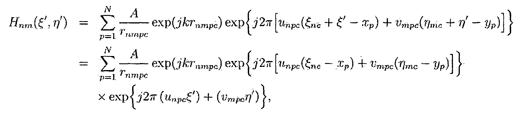
수학식 10
여기에서, r
nmpc 는 p번째 물체 점과 (n,m)번째 세그먼트 사이의 거리이고, u
npc 와 v
mpc 는 (n,m)번째 세그먼트의 중심에서 정해진 국소 공간주파수이다. 수학식 10에서 각 세그먼트의 복수 함수는 거리 위상, 그 세그먼트의 위치 위상과 각 물체 점에 해당하는 싸인 함수로 이루어질 수 있다. 세그먼트의 푸리에 변환, 관련 위상을 갖는 싸인 고조파 함수는 아래의 수학식 11과 같다.
[규칙 제26조에 의한 보정 02.07.2012]
수학식 11 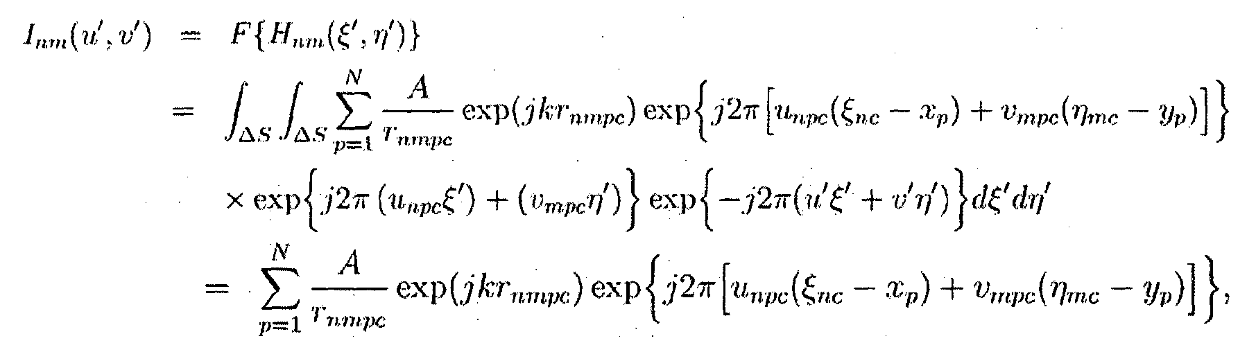
수학식 11
여기에서, u'=u
npc 이고 v'=v
mpc 이다. 이것은 각 물체 점에 해당하는 세그먼트의 스펙트럼이 2차원 싸인 함수의 복소 진폭으로 이루어지고, 세그먼트의 스펙트럼의 역푸리에 변환이 싸인 고조파 함수(홀로그램 프린지 패턴)를 생성함을 의미한다.
따라서, 간략화 방식에서의 정확한 홀로그래픽 프린지 패턴은 컨티뉴어스 도메인에서 2차원 복소 싸인 함수의 복소 진폭의 역 푸리에 변환에 의해 생성될 수 있다.
[규칙 제26조에 의한 보정 02.07.2012]
디스크리트 공간주파수와 디스크리트 공간 영역이 디지털 시스템을 위해 고려되어야 한다. 디스크리트 영역에서는 수학식 10과 11의 Hnm(ξ',η')과 Inm (u',v')의 복소 함수인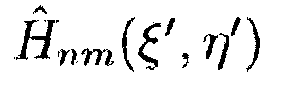 와
와 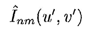 는 아래의 수학식 12와 13으로 표현될 수 있다.
디스크리트 공간주파수와 디스크리트 공간 영역이 디지털 시스템을 위해 고려되어야 한다. 디스크리트 영역에서는 수학식 10과 11의 Hnm(ξ',η')과 Inm (u',v')의 복소 함수인
[규칙 제26조에 의한 보정 02.07.2012]
수학식 12 
수학식 12
[규칙 제26조에 의한 보정 02.07.2012]
수학식 13 
수학식 13
[규칙 제26조에 의한 보정 02.07.2012]
여기에서,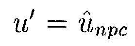 이고
이고 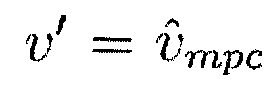 이다. 공간주파수
 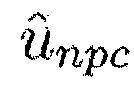 와
와 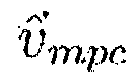 는
는  와
와  이고, 여기에서 Δunpc
와 Δvmpc
는 미지이다. 따라서, 디지털화 에러는 공간주파수 영역의 디지털화에 의해 야기될 수도 있는데,
이고, 여기에서 Δunpc
와 Δvmpc
는 미지이다. 따라서, 디지털화 에러는 공간주파수 영역의 디지털화에 의해 야기될 수도 있는데,  에 의해 표현될 수 있다. 이러한 에러는 디지털화된 공간주파수 영역상에서 더 작은 디지털화 단계에 의해 감소될 수 있다.
여기에서,
[규칙 제26조에 의한 보정 02.07.2012]
한편, 디지털 홀로그램을 실시간으로 계산하여 빠른 속도로 생성하기 위한 알고리즘을 다음과 같이 구현하는 것이 가능하다. 첫 단계에서는 3차원 객체에 대한 3차원 정보를 추출하고, 추출된 3차원 정보를 이용하여 분할된 홀로그램 평면(세그멘트)에 대한 복소진폭 분포(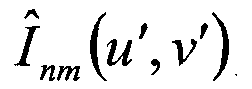 ) 를 아래 수학식 14에 의해 산출가능하다.
한편, 디지털 홀로그램을 실시간으로 계산하여 빠른 속도로 생성하기 위한 알고리즘을 다음과 같이 구현하는 것이 가능하다. 첫 단계에서는 3차원 객체에 대한 3차원 정보를 추출하고, 추출된 3차원 정보를 이용하여 분할된 홀로그램 평면(세그멘트)에 대한 복소진폭 분포(
[규칙 제26조에 의한 보정 02.07.2012]
수학식 14 
수학식 14
산출된 각 세그멘트에 대한 복소진폭 분포는 아래 수학식 15에 의해 역 퓨리에 변환(inverse Fourier transform)을 한다.
[규칙 제26조에 의한 보정 02.07.2012]
수학식 15 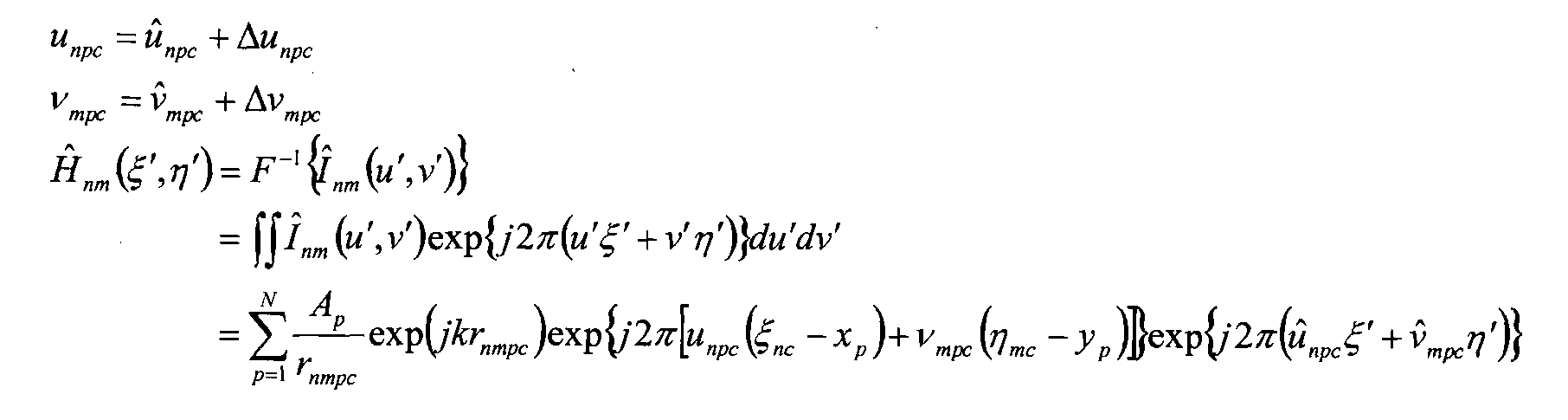
수학식 15
변환된 최종 결과는 해당 세그멘트에 대한 생성된 디지털 홀로그램(holographic fringe pattern)이 된다.
본 발명은 전술한 실시예에 국한되지 않고 본 발명의 기술사상이 허용하는 범위 내에서 다양하게 변형하여 실시할 수가 있다.
Claims (1)
- [규칙 제26조에 의한 보정 02.07.2012]
디지털 홀로그램을 실시간으로 계산하여 빠른 속도로 생성하기 위한 알고리즘으로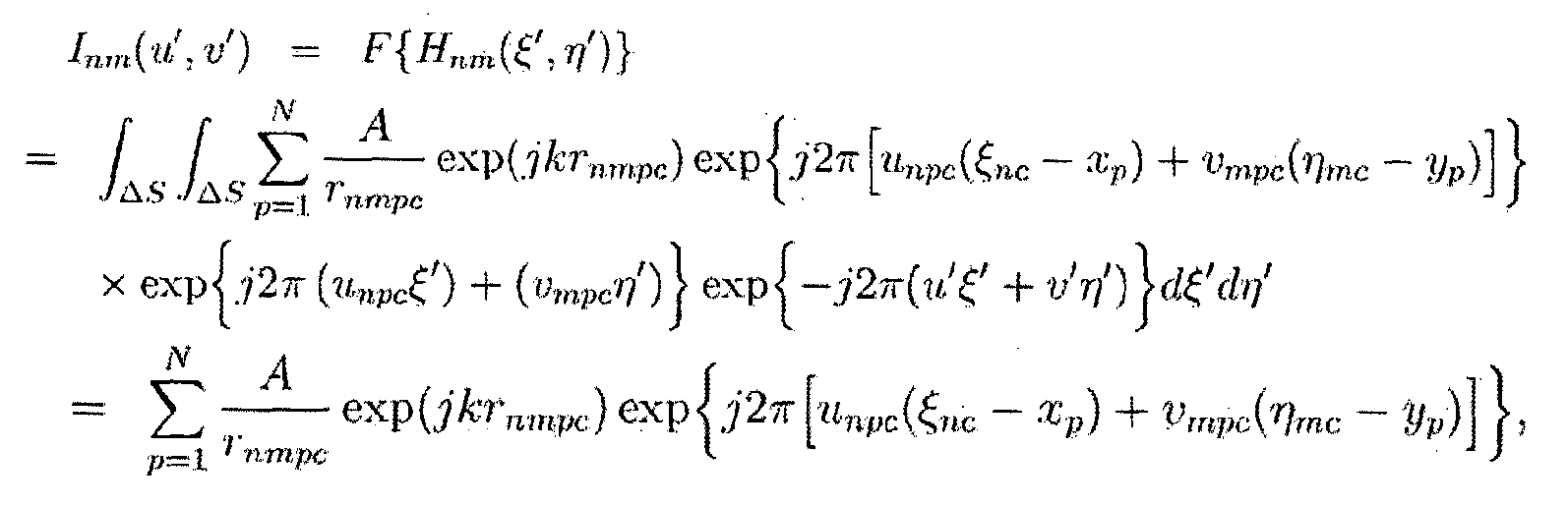 를 사용하여 신속 디지털 홀로그램 생성을 위한 간략화 방법.
Applications Claiming Priority (2)
| Application Number | Priority Date | Filing Date | Title |
|---|---|---|---|
| KR1020110036030A KR101308011B1 (ko) | 2011-04-19 | 2011-04-19 | 디지털 홀로그램 생성 방법 |
| KR10-2011-0036030 | 2011-04-19 |
Publications (2)
| Publication Number | Publication Date |
|---|---|
| WO2012144834A2 true WO2012144834A2 (ko) | 2012-10-26 |
| WO2012144834A3 WO2012144834A3 (ko) | 2013-03-07 |
Family
ID=47042056
Family Applications (1)
| Application Number | Title | Priority Date | Filing Date |
|---|---|---|---|
| PCT/KR2012/003025 Ceased WO2012144834A2 (ko) | 2011-04-19 | 2012-04-19 | 신속 디지털 홀로그램 생성을 위한 간략화 방법 |
Country Status (2)
| Country | Link |
|---|---|
| KR (1) | KR101308011B1 (ko) |
| WO (1) | WO2012144834A2 (ko) |
Cited By (1)
| Publication number | Priority date | Publication date | Assignee | Title |
|---|---|---|---|---|
| US11175626B2 (en) | 2017-12-04 | 2021-11-16 | Naeilhae, Co. Ltd. | On-axis and off-axis digital hologram generating device and method |
Families Citing this family (3)
| Publication number | Priority date | Publication date | Assignee | Title |
|---|---|---|---|---|
| KR102434359B1 (ko) | 2016-08-29 | 2022-08-22 | 주식회사 내일해 | 정축 및 탈축 디지털 홀로그램 생성 장치 및 방법 |
| KR102627448B1 (ko) | 2018-03-09 | 2024-01-23 | 주식회사 내일해 | 정축 및 탈축 디지털 홀로그램 생성 장치 및 방법 |
| KR102161950B1 (ko) * | 2018-12-07 | 2020-10-06 | 한국전자기술연구원 | 세그먼테이션을 이용한 홀로그램 생성 방법 |
Family Cites Families (4)
| Publication number | Priority date | Publication date | Assignee | Title |
|---|---|---|---|---|
| DE102007023739B4 (de) * | 2007-05-16 | 2018-01-04 | Seereal Technologies S.A. | Verfahren zum Rendern und Generieren von Farbvideohologrammen in Echtzeit und holographische Wiedergabeeinrichtung |
| KR100837365B1 (ko) | 2007-07-27 | 2008-06-12 | 광운대학교 산학협력단 | 룩업 테이블을 이용한 컴퓨터 형성 홀로그램 생성과 재생방법 및 그 장치 |
| JP5266923B2 (ja) | 2008-07-17 | 2013-08-21 | 沖電気工業株式会社 | 位置利用サービス提供装置、アクセス手段通知サービス装置、ユーザ端末装置、サービス提供システム及びサービス提供方法 |
| KR101021127B1 (ko) * | 2009-04-06 | 2011-03-14 | 광운대학교 산학협력단 | 룩업 테이블과 영상의 공간적 중복성을 이용한 컴퓨터 형성 홀로그램 산출 방법 및 그 장치 |
-
2011
- 2011-04-19 KR KR1020110036030A patent/KR101308011B1/ko active Active
-
2012
- 2012-04-19 WO PCT/KR2012/003025 patent/WO2012144834A2/ko not_active Ceased
Cited By (1)
| Publication number | Priority date | Publication date | Assignee | Title |
|---|---|---|---|---|
| US11175626B2 (en) | 2017-12-04 | 2021-11-16 | Naeilhae, Co. Ltd. | On-axis and off-axis digital hologram generating device and method |
Also Published As
| Publication number | Publication date |
|---|---|
| KR101308011B1 (ko) | 2013-09-12 |
| WO2012144834A3 (ko) | 2013-03-07 |
| KR20120118582A (ko) | 2012-10-29 |
Similar Documents
| Publication | Publication Date | Title |
|---|---|---|
| Pedrini et al. | Shape measurement of microscopic structures using digital holograms | |
| Zuo et al. | Direct continuous phase demodulation in digital holography with use of the transport-of-intensity equation | |
| WO2012144834A2 (ko) | 신속 디지털 홀로그램 생성을 위한 간략화 방법 | |
| Wang et al. | Fast diffraction calculation of cylindrical computer generated hologram based on outside-in propagation model | |
| Ma et al. | A novel feed-forward neural network-based method for fast hologram generation | |
| JP6757307B2 (ja) | 回折素子の設計方法 | |
| CN114967398A (zh) | 基于深度学习的大尺寸二维计算全息图实时生成方法 | |
| Hossain et al. | A Novel Implementation of Computer Generated Hologram for Highly Secured Communication Using Gerchberg-Saxton (GS) Algorithm | |
| JP3653360B2 (ja) | 計算機ホログラム作成方法及び装置 | |
| Nishi et al. | Fast calculation of computer-generated Fresnel hologram utilizing distributed parallel processing and array operation | |
| CN119937160B (zh) | 一种基于相干结构调控的高阶确定性涡旋产生方法与装置 | |
| Kang et al. | Quality comparison and acceleration for digital hologram generation method based on segmentation | |
| KR20210061264A (ko) | 메쉬 기반 초고해상도 컴퓨터 생성 홀로그램 합성 방법 및 장치 | |
| Maeda et al. | Phase-shifting digital holography without precise alignment of optical elements by using wavefront copy effect of a diffraction grating | |
| Yang | Optical design for far-field light shaping | |
| US4314739A (en) | Holographic method for conversion of waves | |
| CN118096802B (zh) | 一种基于并行任意阶拓扑光学微分的图像处理方法及装置 | |
| CN121454775A (zh) | 基于交叉相位调制的4f系统傅里叶平面成像方法与装置 | |
| Soares et al. | Moiré evaluation with fringe patterns of interferograms, holograms, moirégrams and specklegrams | |
| JP2001524697A (ja) | ホログラム合成のための方法及び装置 | |
| Li et al. | Hybrid Iterative Constrained Hologram Generation Method for Multi Plane Imaging | |
| Kakue | Light Wave, Diffraction, and Holography | |
| Rani et al. | Performance evaluation of different optical schemes for realization of holographic printers | |
| London | Fourier Optics and Deep Learning Methods for Fast 3D Reconstruction in Digital Holography | |
| Kumar et al. | Multiple imaging with an aberration optimized hololens array |
Legal Events
| Date | Code | Title | Description |
|---|---|---|---|
| 121 | Ep: the epo has been informed by wipo that ep was designated in this application |
Ref document number: 12774185 Country of ref document: EP Kind code of ref document: A2 |
|
| NENP | Non-entry into the national phase |
Ref country code: DE |
|
| 122 | Ep: pct application non-entry in european phase |
Ref document number: 12774185 Country of ref document: EP Kind code of ref document: A2 |