WO2012144273A1 - 光出射用エンドキャップの製造方法 - Google Patents
光出射用エンドキャップの製造方法 Download PDFInfo
- Publication number
- WO2012144273A1 WO2012144273A1 PCT/JP2012/054662 JP2012054662W WO2012144273A1 WO 2012144273 A1 WO2012144273 A1 WO 2012144273A1 JP 2012054662 W JP2012054662 W JP 2012054662W WO 2012144273 A1 WO2012144273 A1 WO 2012144273A1
- Authority
- WO
- WIPO (PCT)
- Prior art keywords
- glass rod
- core
- refractive index
- light
- optical fiber
- Prior art date
- Legal status (The legal status is an assumption and is not a legal conclusion. Google has not performed a legal analysis and makes no representation as to the accuracy of the status listed.)
- Ceased
Links
Images




Classifications
-
- G—PHYSICS
- G02—OPTICS
- G02B—OPTICAL ELEMENTS, SYSTEMS OR APPARATUS
- G02B6/00—Light guides; Structural details of arrangements comprising light guides and other optical elements, e.g. couplings
- G02B6/24—Coupling light guides
- G02B6/26—Optical coupling means
- G02B6/262—Optical details of coupling light into, or out of, or between fibre ends, e.g. special fibre end shapes or associated optical elements
-
- H—ELECTRICITY
- H01—ELECTRIC ELEMENTS
- H01S—DEVICES USING THE PROCESS OF LIGHT AMPLIFICATION BY STIMULATED EMISSION OF RADIATION [LASER] TO AMPLIFY OR GENERATE LIGHT; DEVICES USING STIMULATED EMISSION OF ELECTROMAGNETIC RADIATION IN WAVE RANGES OTHER THAN OPTICAL
- H01S3/00—Lasers, i.e. devices using stimulated emission of electromagnetic radiation in the infrared, visible or ultraviolet wave range
- H01S3/05—Construction or shape of optical resonators; Accommodation of active medium therein; Shape of active medium
- H01S3/06—Construction or shape of active medium
- H01S3/063—Waveguide lasers, i.e. whereby the dimensions of the waveguide are of the order of the light wavelength
- H01S3/067—Fibre lasers
- H01S3/06708—Constructional details of the fibre, e.g. compositions, cross-section, shape or tapering
- H01S3/06745—Tapering of the fibre, core or active region
-
- H—ELECTRICITY
- H01—ELECTRIC ELEMENTS
- H01S—DEVICES USING THE PROCESS OF LIGHT AMPLIFICATION BY STIMULATED EMISSION OF RADIATION [LASER] TO AMPLIFY OR GENERATE LIGHT; DEVICES USING STIMULATED EMISSION OF ELECTROMAGNETIC RADIATION IN WAVE RANGES OTHER THAN OPTICAL
- H01S3/00—Lasers, i.e. devices using stimulated emission of electromagnetic radiation in the infrared, visible or ultraviolet wave range
- H01S3/09—Processes or apparatus for excitation, e.g. pumping
- H01S3/091—Processes or apparatus for excitation, e.g. pumping using optical pumping
- H01S3/094—Processes or apparatus for excitation, e.g. pumping using optical pumping by coherent light
- H01S3/0941—Processes or apparatus for excitation, e.g. pumping using optical pumping by coherent light of a laser diode
- H01S3/09415—Processes or apparatus for excitation, e.g. pumping using optical pumping by coherent light of a laser diode the pumping beam being parallel to the lasing mode of the pumped medium, e.g. end-pumping
Definitions
- the present invention relates to a method of manufacturing an end cap for light emission that can emit light having a desired emission shape.
- a fiber laser device is known as one of laser devices.
- the fiber laser device includes an amplification optical fiber to which a rare earth element is added, light is amplified by the amplification optical fiber, and the amplified light is output from the end of the amplification optical fiber.
- Patent Document 1 listed below describes such a fiber laser device.
- an end cap for light emission (hereinafter simply referred to as an end cap) is formed of a glass rod having a diameter larger than that of the core of the amplification optical fiber at the end of the amplification optical fiber. Sometimes called a cap).
- the light amplified by the amplification optical fiber is input from the amplification optical fiber to the end cap.
- the light input to the end cap is output from the end of the end cap after the diameter is expanded according to the numerical aperture of the amplification optical fiber. In this way, the light output density at the output end of the end cap is reduced by increasing the diameter of the light.
- the end portion of the end cap made of a glass rod is fused to the end portion of the amplification optical fiber.
- the end where the end cap of the amplification optical fiber is fused is not in the direction along the axis of the amplification optical fiber so that the light reflected by the end face does not enter the core of the amplification optical fiber. In some cases, it is formed to be inclined from a vertical plane.
- the end cap is fused to such an amplification optical fiber, it is difficult to fuse the amplification optical fiber and the end cap in a state where the respective axial directions are aligned on a straight line.
- the axial direction of the end cap is inclined with respect to the axial direction of the amplification optical fiber, and the amplification optical fiber and the end cap may be fused.
- the axial direction of the end cap is oblique with respect to the axial direction of the amplification optical fiber
- the light input from the amplification optical fiber to the end cap is in the direction along the axis of the end cap in the end cap. Not proceed. Therefore, part of the light reaches the side surface of the end cap before the diameter of the light is sufficiently expanded, and part of the light is diffusely reflected on the side surface of the end cap.
- the present inventor uses an end cap including a glass rod in which a waveguide structure along the axial direction is formed on the input end side and this waveguide structure is not formed on the output end side.
- NA numerical aperture
- a glass rod in which a dopant having a high refractive index such as germanium oxide is added to the core portion of the glass rod is used on the input end side of the glass rod.
- a dopant having a high refractive index such as germanium oxide
- the refractive index of the region to which the dopant is added on the input end side is increased to form a waveguide structure.
- an on-line monitor is used to form the waveguide. It is desirable.
- an optical fiber is connected to the input end of the glass rod, light for monitoring is input from the optical fiber to the glass rod, and light output from the output end of the glass rod is observed. Therefore, ultraviolet rays are irradiated with the optical fiber connected to the glass rod. In this state, it is difficult to irradiate ultraviolet rays only on the input end side of the glass rod, and this ultraviolet rays tend to irradiate the output end of the optical fiber.
- germanium oxide is added to the core, so when the glass rod is irradiated with ultraviolet rays, the optical fiber is also irradiated with ultraviolet rays as described above, and the refractive index of the core of the glass rod is increased. At the same time, the refractive index of the core of the optical fiber further increases, and the relative refractive index difference with respect to the cladding of the core increases. For this reason, the mode field diameter (MFD) of the light propagating through the optical fiber is reduced and the NA of the light is increased. Therefore, the light input from the optical fiber to the glass rod has a large NA, and the diameter tends to spread.
- MFD mode field diameter
- an object of the present invention is to provide a method for manufacturing a light emitting end cap capable of emitting laser light having a desired emission shape.
- a method of manufacturing a light emitting end cap according to the present invention includes a cladding and a core formed along a central axis of the cladding, and the refractive index of the core is the refractive index of the cladding.
- the core is prepared with a glass rod to which a dopant that has a refractive index higher than that of the clad is added when irradiated with ultraviolet rays.
- the core of the glass rod is A preparation step of preparing an optical fiber having a core and a cladding whose refractive index is increased by adding a dopant that does not increase the refractive index, and the axis of the core of the glass rod and the axis of the core of the optical fiber And a connecting step of connecting one end of the glass rod and one end of the optical fiber, and a front of the optical fiber from the core. While observing the light output from the glass rod by inputting light to the core of the glass rod, the one end of the glass rod is irradiated with ultraviolet rays on the one end side of the glass rod. And a waveguide structure forming step of forming a waveguide structure only on the side.
- the waveguide structure is not formed in the glass rod whose core refractive index is lower than the refractive index of the cladding.
- the core of the glass rod is added with a dopant whose refractive index increases when irradiated with ultraviolet rays, and the one end side of the glass rod is irradiated with ultraviolet rays on one end side of the glass rod.
- a waveguide structure is formed only on the substrate.
- one end is used as a light input surface, and the other end is used as a light output surface, so that the light is inclined with respect to the axial direction of the glass rod. Can be transmitted even in the axial direction of the glass rod (the axial direction of the cladding). Since the waveguide structure is not formed on the output surface side of the glass rod, the light propagating through the core on the input surface side of the glass rod is expanded in diameter on the output surface side and emitted from the other end. To do.
- an optical fiber having a core whose refractive index is increased by a dopant that does not increase its refractive index when compared with the core of the glass rod when irradiated with ultraviolet rays is connected.
- Light is input from the fiber to the glass rod, and the glass rod is irradiated with ultraviolet rays while observing this light. That is, ultraviolet rays are irradiated using an online monitor. As described above, when ultraviolet rays are applied to the input surface side of the glass rod, the ultraviolet rays tend to be applied to the optical fiber connected to the glass rod.
- the refractive index of the core of the optical fiber is equal to that of the glass rod even when the optical fiber core connected to the glass rod is irradiated with ultraviolet rays. It does not rise as the refractive index of the core.
- a glass rod is added to the core of this optical fiber, since the refractive index is increased only by addition, and the dopant is suppressed from increasing in refractive index even when irradiated with ultraviolet rays after the addition.
- a waveguide structure is formed by irradiating UV light onto the optical fiber, even if the optical fiber is irradiated with UV light, the change in optical properties of the optical fiber can be suppressed. It can suppress that a change arises. For this reason, it is possible to form an appropriate waveguide structure on the glass rod by irradiating ultraviolet rays while observing light using an on-line monitor.
- a light emitting end cap of the present invention it is possible to manufacture a light emitting end cap capable of emitting laser light having a desired emission shape.
- the optical fiber connected to the glass rod may be used as it is as an optical fiber for laser output, and the glass rod is separated from the optical fiber as a light emitting end cap, and the light emitting end cap is used as another light. It may be used by connecting to a fiber.
- a cutting step of cutting the optical fiber and the glass rod after the waveguide structure forming step may be further provided.
- a hydrogen loading step of performing hydrogen loading on the glass rod may be further provided between the connecting step and the waveguide structure forming step.
- the dopant added to the core of the optical fiber is preferably at least one of aluminum oxide, diphosphorus pentoxide, and titanium oxide, and the dopant added to the core of the glass rod is preferably germanium oxide. .
- quartz to which diphosphorus pentoxide and titanium oxide are added produces a refractive index increase that is smaller than 1/10 of quartz to which germanium oxide is added, and such a difference in refractive index increase.
- the refractive index of the core of the glass rod is sufficiently increased, the influence of the increase in the refractive index of the core of the optical fiber can be ignored in performing online monitoring.
- quartz to which aluminum oxide is added produces a refractive index increase smaller than 1/100 that of quartz to which germanium oxide is added.
- the dopant added to the core of the optical fiber is more preferably aluminum oxide.
- the dopant added to the core of the optical fiber may be aluminum oxide, and the dopant added to the core of the glass rod may be diphosphorus pentoxide.
- an end cap for light emission capable of emitting laser light having a desired emission shape.
- FIG. 1 It is a figure which shows the fiber laser apparatus which concerns on embodiment of this invention. It is sectional drawing which shows the structure in the cross section of the direction perpendicular
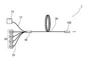
- FIG. 1 is a view showing a fiber laser device using an end cap manufactured by an end cap manufacturing method according to the present embodiment.
- the fiber laser device 1 includes a seed light source 10 that outputs seed light, a pump light source 20 that outputs pump light, an amplification optical fiber 30 that amplifies the seed light, and seed light and pump light.
- An optical combiner 40 that inputs to the amplification optical fiber 30 and a glass rod 100 as an end cap that receives light output from the amplification optical fiber 30 are provided as main components.
- the seed light source 10 is composed of a Fabry-Perot type or fiber ring type fiber laser device, and outputs seed light.
- the seed light is pulsed light or continuous light.
- the active element added to the core of the amplification optical fiber 30 is ytterbium (Yb) as described later, the wavelength is, for example, 1064 nm.
- the seed light output from the seed light source 10 propagates through the seed light fiber 15 connected to the seed light source 10.
- the seed light fiber 15 is composed of, for example, a single mode fiber. In this case, the seed light input to the seed light fiber 15 propagates through the seed light fiber in a single mode.
- the excitation light source 20 is composed of a plurality of laser diodes (LD). As described above, when the active element added to the core of the amplification optical fiber 30 is ytterbium (Yb), the pumping light source 20 outputs pumping light having a wavelength of 976 nm, for example.
- the excitation light output from the excitation light source propagates through the excitation fiber 25 connected to the excitation light source.
- the excitation fiber 25 is made of, for example, a multimode fiber. In this case, the excitation light input to the excitation fiber 25 propagates through the excitation fiber 25 in multimode.
- FIG. 2 is a diagram showing a cross-sectional structure perpendicular to the longitudinal direction of the amplification optical fiber 30.
- the amplification optical fiber 30 includes a core 31, a clad 32 surrounding the core 31, an outer clad 33 surrounding the clad 32, and a coating layer 34 covering the outer clad 33.
- the refractive index of the cladding 32 is lower than the refractive index of the core 31, and the refractive index of the outer cladding 33 is further lower than the refractive index of the cladding 32.
- the diameter of the core 31 is, for example, 9 ⁇ m
- the outer diameter of the cladding 32 is, for example, 120 ⁇ m
- the outer diameter of the resin cladding is, for example, 250 ⁇ m.
- the material constituting the core 31 include an element such as germanium oxide that increases the refractive index, and a predetermined wavelength that is excited by excitation light output from the excitation light source 20 and output from the seed light source.
- an active element include rare earth elements.
- rare earth elements include erbium (Er), thulium (Tm), cerium (Ce), neodymium (Nd), and europium (Eu) in addition to Yb. Can be mentioned. Furthermore, bismuth (Bi) etc. other than rare earth elements are mentioned as an active element.
- the pure quartz to which no dopant is added is mentioned, for example.
- the material constituting the outer cladding 33 include ultraviolet curable resin and quartz to which fluorine is added, and examples of the material constituting the coating layer 34 include ultraviolet curable resin. In the case where the material constituting 33 is an ultraviolet curable resin, the ultraviolet curable resin constituting the outer cladding 33 and the ultraviolet curable resin constituting the coating layer 34 are different types.
- the optical combiner 40 is configured by fusing the seed light fiber 15 connected to the seed light source 10, the excitation fiber 25 connected to the pump light source 20, and the amplification optical fiber 30. Specifically, the end portion of the amplification optical fiber 30 is aligned such that the central axis of the core of the seed light fiber 15 and the central axis of the core 31 of the amplification optical fiber 30 are aligned in the longitudinal direction. And the end of the seed light fiber 15 are end-face connected. Further, the core of the excitation fiber 25 and the clad 32 of the amplification optical fiber 30 are aligned so as to be aligned in the longitudinal direction, and the end of the amplification optical fiber 30 and the end of the excitation fiber 25 are end-face connected. Has been.
- the seed light fibers 15 are connected to the amplification optical fibers 30 such that the side surfaces are surrounded by the plurality of excitation fibers 25.
- the optical combiner 40 the seed light from the seed light source 10 and the excitation light from the excitation light source 20 are input to the amplification optical fiber 30.
- the end of the amplification optical fiber 30 opposite to the optical combiner 40 side is fused to the glass rod 100.
- FIG. 3 is a view showing a state of the glass rod 100 shown in FIG. Specifically, FIG. 3A is a view of the glass rod 100 as viewed from the side, and FIG. 3B is a view showing the refractive index distribution of the glass rod 100.
- the glass rod 100 has a cylindrical shape having an input end 151 which is one end and an output end 152 which is the other end.
- the glass rod 100 includes a core 110 and a clad 120 surrounding the core 110, and the core 110 is formed along the central axis of the clad 120, that is, the central axis of the glass rod 100.
- the end 35 of the amplification optical fiber 30 is fused to the input end 151 of the glass rod 100.
- the core 31 of the amplification optical fiber 30 and the core 110 of the glass rod are overlapped in the longitudinal direction of the glass rod 100, and the output end 35 of the amplification optical fiber 30 is the input end 151 of the glass rod. Is fused.
- the covering layer 34 is omitted.
- the diameter of the glass rod 100 is made larger than the diameter of the core 31 of the amplification optical fiber 30, and the diameter of the glass rod 100 in this embodiment is made larger than the diameter of the clad 32 of the amplification optical fiber 30.
- the glass rod 100 has a diameter of 400 ⁇ m or more, and the length is, for example, propagation.
- the numerical aperture of the mode is 0.1 and the clad diameter is 400 ⁇ m as described above, it is set to 1.5 mm to 2.0 mm.
- the diameter of the core 110 is preferably equal to the diameter of the core of the amplification optical fiber 30 from the viewpoint of light propagation.
- the glass rod 100 in this embodiment is divided into three regions in the longitudinal direction, and in this description, the region 101, the region 102, and the region 103 are sequentially formed from the input end 151 of the glass rod 100.
- the area 101 has a predetermined length L1. As shown in FIG. 3B, in the region 101, the refractive index n11 of the core 110 is higher than the refractive index n21 of the clad 120, and the refractive index n11 of the core 110 and the refractive index of the clad 120. Both n21 are constant.
- the length L1 of this region 101 is 0.3 mm or more when the NA of the propagation mode of the amplification optical fiber 30 is 0.1 and the diameter of the core 110 is 30 ⁇ m. It is preferable from the viewpoint.
- the area 102 is set to a predetermined length L2. As shown in FIG. 3B, in the region 102, the refractive index n12 of the core 110 is gradually lowered from the input end 151 side toward the output end 152 side. Further, the refractive index n22 of the clad 120 slightly decreases from the input end 151 side toward the output end 152 side, but is substantially constant.
- the refractive index n12 of the core 110 in the region 102 is configured to be equal to the refractive index n11 in the region 101 of the core 110 on the most input end 151 side of the region 102, and is higher than the refractive index n22 of the cladding 120. It is said that.
- the refractive index difference between the core 110 and the cladding 120 gradually decreases toward the output end 152 side in the region 102, and the refractive index n12 of the core 110 and the cladding 120 on the most output side 152 side of the region 102.
- the refractive index n22 is an equivalent refractive index.
- the length L2 of the region 102 is preferably longer than the wavelength of the light input to the glass rod 100, and more than twice the wavelength of the light, from the viewpoint of suppressing the Fresnel reflected light of the light. preferable.
- the region 103 extending to the output end 152 adjacent to the region 102, there is no difference in refractive index between the core 110 and the clad 120, and the refractive indexes are equal to each other.
- the lower limit of the length L3 of the region 103 is determined by the NA of the region 101 and the power density allowed at the emission end, and the upper limit is determined by the NA of the region 101 and the outer diameter of the glass rod 100.
- the length L1 of the region 101 of the glass rod 100 is 0.3 mm or more.
- the length L2 of the region 102 is 2 ⁇ m or more, and the region 103 is, for example, 1.5 mm to 2.0 mm.
- the material used for the glass rod 100 include quartz to which germanium oxide (GeO 2 ) is added as a material for the core 110, and aluminum oxide (Al 2 O 3 ) as a material for the cladding 120. Quartz.
- seed light is output from the seed light source 10 and excitation light is output from the excitation light source 20.
- the seed light output from the seed light source 10 propagates through the seed light fiber 15, and the excitation light output from the excitation light source 20 propagates through the excitation fiber 25.
- the seed light and the excitation light are input to the amplification optical fiber 30 in the optical combiner 40.
- the seed light input to the amplification optical fiber 30 propagates through the core 31 of the amplification optical fiber 30, and the excitation light mainly propagates through the cladding 32 of the amplification optical fiber 30.
- the amplified seed light is output from the end portion 35 of the amplification optical fiber 30 as output light.
- the output light output from the end 35 of the amplification optical fiber 30 is input to the core 110 of the glass rod 100.
- the end portion 35 of the amplification optical fiber 30 is not perpendicular to the central axis of the amplification optical fiber 30, and the central axis of the glass rod 100 and the central axis of the amplification optical fiber 30 are In some cases, the amplification optical fiber 30 and the glass rod 100 are fused together in an inclined state. Even in such a case, the output light output from the end portion 35 of the amplification optical fiber 30 propagates through the core 110 of the glass rod 100.
- the laser beam propagating through the core 110 propagates through the core 110 in the region 101.
- the refractive index difference between the core 110 and the clad 120 gradually decreases, so that light propagates from the core 110 to the clad 120 in order from light having a large NA.
- the laser light propagating through the core 110 gradually begins to spread into the cladding 120 as it propagates through the region 102.
- the beam diameter of the output light increases according to the NA of the output light.
- the length L2 of the region 102 is longer than the wavelength of the output light, and the refractive index of the core region of the region 102 is gradually smaller than the refractive index of the cladding region of the region 102. Therefore, the reflection to the amplification optical fiber 30 that may occur in the region 102 can be reduced.
- the output light whose diameter is expanded in the glass rod 100 is output from the output end 152 of the glass rod 100.
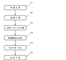
- the manufacturing method of the end cap includes a glass rod 100 in which the refractive index of the core 110 is equal to or lower than the refractive index of the cladding 120, and a preparation step P1 for preparing the dummy fiber 200, and the glass rod 100 and the dummy.
- disconnects the rod 100 and the dummy fiber 200 is provided.
- the glass rod 100 is prepared. In this step, the glass rod 100 is adjusted so that the refractive index of the core 110 and the refractive index of the cladding 120 are equal to each other without being irradiated with ultraviolet rays. A higher dopant is added.
- the material of the core 110 and the clad 120 is not particularly limited, and examples thereof include quartz to which a dopant shown in Table 1 is added.
- quartz to which germanium oxide is added is used as the material of the core 110, and aluminum oxide (Al 2 O 3 ), diphosphorus pentoxide (P 2 O 5 ), and titanium oxide are used as the material of the cladding 120. It shows that one kind of dopant is added in (TiO 2 ) or quartz to which two or more kinds of dopants are co-added is used.
- Germanium oxide is a dopant that increases the refractive index of the core 110 when irradiated with ultraviolet rays.
- Aluminum oxide, diphosphorus pentoxide, and titanium oxide are dopants that can be adjusted so that the refractive index of the clad is raised and the refractive index of the clad 120 is equal to that of the clad 120 without being irradiated with ultraviolet rays. . Further, dopants such as aluminum oxide, diphosphorus pentoxide, and titanium oxide increase the refractive index of the cladding 120 when irradiated with ultraviolet rays, but the refractive index increases by 1 compared to the core 110 to which germanium oxide is added. / 10 or less.
- the refractive index of the core 110 and the refractive index of the clad 120 are equal to each other without being irradiated with ultraviolet rays, and when the glass rod 100 is irradiated with ultraviolet rays, the refractive index of the core 110 is reduced. It becomes higher than the refractive index.
- aluminum oxide is more preferable as the dopant added to the cladding. Quartz to which aluminum oxide is added has an increase in refractive index that is smaller than 1/10 that of quartz to which diphosphorus pentoxide is added. A refractive index difference from the clad 120 can be formed.
- the core 110 is a fluorine that lowers the refractive index for the purpose of adjusting the refractive index of the core 110 to be equal to the refractive index of the clad 120 in a state where ultraviolet rays are not irradiated.
- a dopant such as (F) or boron (B) may be added together with germanium oxide.
- Quartz to which diphosphorus pentoxide is added is used as the material for the core 110, and quartz to which aluminum oxide is added is used as the material for the cladding 120. Quartz to which diphosphorus pentoxide is added has a refractive index 10 times higher than that of quartz to which aluminum oxide is added when irradiated with ultraviolet rays. The refractive index of the cladding 120 and the refractive index of the core 110 are adjusted to be equal to each other with aluminum oxide in a state where no ultraviolet rays are irradiated.
- the core 110 is a fluorine that lowers the refractive index for the purpose of adjusting the refractive index of the core 110 to be equal to the refractive index of the clad 120 in a state where ultraviolet rays are not irradiated.
- a dopant such as boron may be added together with diphosphorus pentoxide.
- the end portion on the side that becomes the outgoing end of the glass rod 100 may be polished by CMP (Chemical Mechanical Polishing) or buffing.
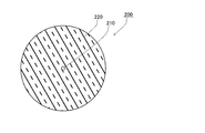
- FIG. 5 is a cross-sectional view showing a structure of the dummy fiber 200 in a cross section perpendicular to the longitudinal direction.
- the dummy fiber 200 is an optical fiber including a core 210 and a clad 220 surrounding the core 210.
- the diameter of the core 210 is the same as that of the core 110 of the glass rod 100, for example.
- the core 210 is made of quartz to which a dopant that does not increase the refractive index as compared with the core 110 of the glass rod 100 when irradiated with ultraviolet rays, and has a higher refractive index than the clad 220.
- a dopant added to the core 210 for example, “dopant added to the cladding” in Table 1 may be read as “dopant added to the core of the dummy fiber”.
- one kind of dopant or two or more kinds of dopants are added or co-added. Quartz to which these dopants are added has a higher refractive index than quartz to which no dopant is added.
- Examples of the material of the clad 220 of the dummy fiber 200 include quartz to which no dopant is added and quartz to which fluorine or boron that lowers the refractive index is added. Therefore, the dummy fiber 200 has a waveguide structure with the refractive index of the core 210 added by these dopants, and can propagate light.
- the dopant of the core 210 of the dummy fiber 200 includes aluminum oxide, diphosphorus pentoxide, and titanium oxide.
- Quartz to which aluminum oxide, diphosphorus pentoxide, and titanium oxide are added as dopants has a slightly higher refractive index when irradiated with ultraviolet rays, but germanium oxide used for the core 110 of the glass rod 100 is added. Compared to quartz, the range of the increase is very small, and even if the quartz to which germanium oxide is added is irradiated with ultraviolet rays so that the refractive index is sufficiently increased, the refractive index does not increase so much.
- the increase in refractive index due to ultraviolet rays differs by 100 times or more.
- the increase in refractive index due to ultraviolet rays differs by 10 times or more when diphosphorus pentoxide or titanium oxide is added.
- the dopant added to the core 110 of the glass rod 100 is germanium oxide and the dopant added to the core 210 of the dummy fiber 200 is aluminum oxide, the core of the glass rod 100 is irradiated when ultraviolet rays are irradiated.
- the refractive index of the core 210 of the dummy fiber 200 is particularly preferable because it can be suppressed to an increase smaller than 1/100.
- aluminum oxide may be cited as the dopant of the core 210 of the dummy fiber 200. It can. Quartz to which aluminum oxide is added as a dopant has a slightly higher refractive index as described above when irradiated with ultraviolet rays, but quartz to which diphosphorus pentoxide used for the core 110 of the glass rod 100 is added. The increase in the refractive index is very small, and even if ultraviolet rays are irradiated so that the refractive index of the quartz to which diphosphorus pentoxide is added is sufficiently increased, the refractive index does not increase so much. Specifically, for example, when diphosphorus pentoxide is added as a dopant and when aluminum oxide is added, the increase in the refractive index due to ultraviolet rays differs by 10 times or more.
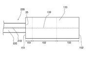
- the glass rod 100 and the dummy fiber 200 are connected. Specifically, the axis of the core 110 of the glass rod 100 and the axis of the core 210 of the dummy fiber 200 are aligned to connect one end 151 of the glass rod 100 and one end of the dummy fiber 200. To do. This connection may be performed, for example, by fusing the end portion 151 of the glass rod and the end portion of the dummy fiber 200 using arc discharge, an oxyhydrogen burner, or a CO 2 laser. Thus, the glass rod 100 and the dummy fiber 200 are connected to each other as shown in FIG.
- the hydrogen loading process is a process in which an object loaded with hydrogen in an atmosphere containing hydrogen of a predetermined concentration is left for a predetermined time at a predetermined pressure and a predetermined temperature.
- the atmosphere is hydrogen
- the atmospheric pressure is 100 atm
- the temperature is 40 ° C.
- the glass rod 100 and the dummy fiber 200 connected to each other are left in the atmosphere for 160 hours or more. In this way, hydrogen is introduced into the core 110 of the glass rod 100.
- ⁇ Waveguide structure forming step P4> Next, one end 151 side (the side to which the dummy fiber is connected) in the length direction of the glass rod 100 is irradiated with ultraviolet rays to form a waveguide structure only on the one end 151 side of the glass rod.
- FIG. 7 is a view schematically showing the waveguide structure forming step P4 in the present manufacturing method.
- the ultraviolet ray UV is irradiated to a part of the glass rod 100 with an irradiation area limited by the mask 2.
- the mask 2 moves relative to the glass rod 100 from the one end 151 side of the glass rod 100 toward the other end 152. Accordingly, the ultraviolet rays UV are irradiated while moving from one end 151 side of the glass rod 100 to the other end 152.
- FIG. 8 is a view showing a profile showing the time for irradiating the glass rod 100 used in this manufacturing method with ultraviolet rays and the refractive index increase of the core 110 and the cladding 120.
- the core 110 is doped with a dopant that causes the refractive index of the core 110 to be higher than the refractive index of the clad 120 when irradiated with ultraviolet rays. Even if the refractive index is the same, the refractive index of the core 110 becomes higher than the refractive index of the clad 120 in accordance with the irradiation of ultraviolet rays.
- the glass rod 100 having the profile shown in FIG. 8 uses quartz in which germanium oxide is added to the core 110, and quartz in which aluminum oxide is added to the clad 120. In FIG. 8, the scale is changed from the actual profile for easy understanding.
- ultraviolet irradiation is performed based on the profile shown in FIG. 8 that is known in advance, but in order to perform more accurate control of ultraviolet irradiation, a dummy as shown by a broken line in FIG. 7 is used.
- Light for online monitoring is input from the fiber 200 to the glass rod 100. Then, while observing the light output from the glass rod 100, the irradiation of the ultraviolet rays UV is controlled.
- the region 101 is irradiated with ultraviolet rays UV.
- the mask 2 moves relative to the glass rod 100 at a constant speed, and ultraviolet rays are irradiated to all the portions of the glass rod 100 in the region 101 for a time t1 shown in FIG. .
- the refractive index n11 of the core 110 is increased and the refractive index of the cladding 120 is slightly increased, but the refractive index is higher than that of the core 110 to which germanium oxide is added. The rise is very small.
- the ultraviolet rays UV irradiating the region 101 may also be irradiated to a part of the dummy fiber 200.
- the core 210 of the dummy fiber 200 has a very small increase in refractive index due to ultraviolet rays as compared with the core 110 of the glass rod 100. Accordingly, even when the refractive index of the core 110 of the glass rod 100 is sufficiently increased, the optical properties of the dummy fiber 200 are not changed by the increase of the refractive index of the core 210 of the dummy fiber 200, and the dummy fiber The light input from 200 to the glass rod 100 does not change so much. That is, when the dummy fiber 200 is irradiated with ultraviolet rays, the refractive index of the core 210 slightly increases. However, the increase in the refractive index of the core 210 is not at a level that affects online monitoring.
- the relative speed of the mask 2 with respect to the glass rod on the input end 151 side is the same as the speed in the region 101, and the speed of the mask 2 with respect to the glass rod increases toward the output end 152 side. It will be lost.
- the ultraviolet ray UV is irradiated on the input end 151 side for substantially the same time as the region 101, and the irradiation time of the ultraviolet ray UV is shortened toward the output end 152 side.
- the ultraviolet ray UV is hardly irradiated on the output end 152 side.
- the refractive index n12 of the core 110 is gradually decreased with respect to the refractive index n22 of the cladding 120 from the input end 151 side to the output end 152 side.
- the region 103 is not irradiated with ultraviolet UV. Therefore, in the region 103, the refractive index n13 of the core 110 and the refractive index n23 of the cladding 120 remain the same.
- a waveguide structure is formed on one end 151 side of the core 110 of the glass rod 100.
- dehydrogenation processing is performed on the glass rod 100.
- the glass rod 100 is heated to a predetermined temperature in an inert gas atmosphere or in the air and left for a predetermined time.
- dehydrogenation processing is performed together with the dummy fiber 200.
- the glass rod 100 connected to the dummy fiber may be left in an air atmosphere heated to 100 ° C. to 150 ° C. for 60 hours or more.
- cleaving process P6> Next, the glass rod 100 and the dummy fiber 200 are cut. In order to cut the glass rod 100 and the dummy fiber 200, for example, cleaving may be performed while leaving a region longer than the required length of the glass rod.
- the glass rod 100 shown in FIG. 3 can be obtained.
- the glass rod 100 is used as an end cap as it is.
- one end 151 of the glass rod 100 may be connected to the amplification optical fiber 30.
- the glass rod 100 is irradiated with ultraviolet rays. That is, ultraviolet rays are irradiated using an online monitor.
- the core 210 of the dummy fiber 200 has a higher refractive index by adding a dopant that suppresses an increase in refractive index than the core 110 of the glass rod 100 when irradiated with ultraviolet rays.
- the refractive index of the core 210 of the dummy fiber 200 is equal to that of the glass even when the ultraviolet rays are also applied to the dummy fiber 200 connected to the glass rod 100. As with the refractive index of the core 110 of the rod 100, it does not increase. Therefore, when the glass rod 100 is irradiated with ultraviolet rays to form a waveguide structure, even if the dummy fibers 200 are irradiated with ultraviolet rays, changes in the optical properties of the dummy fibers 200 can be suppressed. It can suppress that a change arises in the light which inputs into the glass rod 100 from.
- an end cap manufacturing method of the present embodiment it is possible to manufacture an end cap capable of emitting laser light having a desired emission shape.
- the glass rod 100 is divided into three regions, and in the region 102, the refractive index difference between the core 110 and the clad 120 gradually changes along the longitudinal direction.
- the glass rod manufactured by the invention is not limited to this.
- the other form of the end cap manufactured by the manufacturing method of the end cap of the present invention will be described.
- the same referential mark is attached
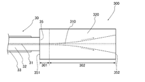
- FIG. 9 is a diagram showing another embodiment of the end cap manufactured by the end cap manufacturing method of the present invention.
- the glass rod 300 has a cylindrical shape having one end 351 as an input end and the other end 352 as an output end.
- the glass rod 300 includes a core 310 and a clad 320 that covers the core 310, and the core 310 is formed along the central axis of the glass rod 300.
- the refractive index of the core 310 in the region 301 having a predetermined length L4 from the input end 351 of the glass rod 300 is higher than the refractive index of the cladding 320 in the region 301, and the refractive index of the core 310 and the refractive index of the cladding 320 are set. Is assumed to be constant.
- the length L4 of this region 301 is 0.2 mm or more when the NA of the propagation mode of the amplification optical fiber 30 is 0.12 and the diameter of the core 310 is 20 ⁇ m. It is preferable from the viewpoint.
- the region 302 having a length L5 extending to the output end 352 adjacent to the region 301 and the output end 352 side there is no difference in refractive index between the core 310 and the clad 320, and the refractive indexes are equal to each other.
- the lower limit of the length L5 of this region 302 is the NA of the mode propagating through the amplification optical fiber 30 and the power density allowed at the output end 352, and the upper limit is the NA of the mode propagating through the amplification optical fiber 30 and the glass rod 300. Determined by the outer diameter of
- Such a glass rod 300 can be manufactured as follows.
- a glass rod and a dummy fiber are prepared in the same manner as in the manufacturing method in the above embodiment (preparation step), and the glass rod and the dummy fiber are connected in the same manner as in the above embodiment (connection step).
- a hydrogen loading process is performed in the same manner as in the embodiment (hydrogen loading step).
- ultraviolet light is irradiated to the region 301 to form a waveguide structure in the region 301 (waveguide structure forming step).
- ultraviolet rays are irradiated while performing online monitoring in the same manner as in the above embodiment.
- the ultraviolet irradiation may be performed in the same manner as the ultraviolet irradiation in the region 101 of the manufacturing method in the above embodiment.
- the refractive index of the core 310 is made higher than that of the clad 320 in the region 301, and a waveguide structure is formed in the region 301.
- the dehydrogenation process is performed in the same manner as in the first embodiment (dehydrogenation process), and the dummy fiber and the glass rod are separated (cutting process). In this way, the glass rod 300 is obtained.
- the end cap manufactured by the end cap manufacturing method of the present invention can be modified as appropriate, and in the above-described embodiment, the region 101 where the refractive index difference between the core 110 and the cladding 120 is constant is not necessarily required. . Even in the absence of the region 101, the refractive index n12 of the core 110 is higher than the refractive index n22 of the cladding 120 on the input end 151 side of the region 102, so that the output light input to the glass rod 100 propagates through the core 110. To do.
- the refractive index n13 of the core 110 in the region 103 and the refractive index n23 of the clad 120 are equal, but it is not necessarily equal.
- the refractive index n23 of the clad 120 is the same as that of the core 110.
- the configuration may be higher than the refractive index n13. Even in this case, in the region 103, the diameter of the output light can be expanded without forming the waveguide structure.
- the refractive index of the core 310 and the refractive index of the clad 320 in the region 302 are equal to each other.
- the refractive index may be higher than the refractive index of the core 310. Even in this case, the diameter of the output light can be expanded in the region 302.
- the glass rods 100 and 300 are not particularly covered with anything.
- the glass rods 100 and 300 are formed with a second clad having a higher refractive index than the clads 120 and 320. It may be covered.
- the other end portions 152 and 352 which are output ends it is possible to prevent the reflected output light from being unnecessarily emitted from the side surfaces of the glass rods 100 and 300. Can do.
- the glass rods 100 and 300 and the dummy fiber are cut, but the dummy fiber may not be cut.
- the dummy fiber may be connected to the amplification optical fiber 30.
- hydrogen is introduced into the cores 110 and 310 of the glass rods 100 and 300 in the hydrogen loading step P3.
- this treatment is not essential and the hydrogen loading step P3 is not performed. Also good. In that case, the dehydrogenation step P5 is also unnecessary.
- Example 1 First, quartz having a diameter of 30 ⁇ m and adding 3.4% by mass of GeO 2 as a core, quartz having an outer diameter of 400 ⁇ m and adding 2.5% by mass of Al 2 O 3 as a cladding, and having a length of 1. An 8 mm glass rod was prepared. At this time, the refractive indexes of the core and the clad were equal. In addition, a dummy fiber was prepared in which quartz having a diameter of 30 ⁇ m and 1.35 mass% of Al 2 O 3 added as a core and quartz having an outer diameter of 400 ⁇ m and no dopant added as a clad were prepared.
- the glass rod core central axis and the dummy fiber core central axis were aligned, and one end of the glass rod and one end of the dummy fiber were fused and connected.
- measurement light was propagated from the dummy fiber to the glass rod, and the side surface of the glass rod was irradiated with ultraviolet rays while observing the light output from the glass rod (while performing online monitoring).
- the intensity of the ultraviolet rays at this time was set to 2 mJ / mm, and the position where the ultraviolet rays were irradiated was gradually changed by starting to irradiate the ultraviolet rays from the side where the dummy fiber of the glass rod was connected.
- the spot of the measurement light output from the glass rod reached a desired beam diameter, the irradiation of ultraviolet rays was stopped and a waveguide was formed only on the side of the glass rod where the dummy fiber was connected.
- the dummy fiber was cut to produce an end cap made of a glass rod.
- the produced end cap was connected to the emission end of the fiber laser device.
- output light was emitted from this fiber laser device, it was possible to output output light having a desired beam shape.
- Example 2 The same glass rod and dummy fiber as the glass rod and dummy fiber of Example 1 were prepared, and each was connected in the same manner as in Example 1.
- the hydrogen loading treatment was performed by leaving the glass rod connected with the dummy fiber in a chamber of 100 atm in a hydrogen atmosphere and 50 ° C. environment for 168 hours.
- light having an NA equivalent to the output light of the fiber laser is input to the dummy fiber from the optical fiber that is spatially coupled to the dummy fiber, and the glass rod is irradiated with ultraviolet rays while performing on-line monitoring to guide the light.
- a structure was formed.
- dehydrogenation treatment was performed.
- the dehydrogenation treatment was performed by leaving the glass rod on which the waveguide structure was formed for 72 hours together with the dummy fiber in a chamber at 100 ° C. and atmospheric pressure in an air atmosphere.
- the dummy fiber was cut to produce an end cap made of a glass rod.
- the produced end cap was connected to the emission end of the fiber laser device.
- output light was emitted from this fiber laser device, it was possible to output output light having a desired beam shape.
- the light emitting end cap capable of emitting laser light having a desired emission shape is manufactured. confirmed.
- an end cap for light emission that can emit laser light having a desired emission shape.
Landscapes
- Physics & Mathematics (AREA)
- General Physics & Mathematics (AREA)
- Optics & Photonics (AREA)
- Lasers (AREA)
- Optical Couplings Of Light Guides (AREA)
- Optical Fibers, Optical Fiber Cores, And Optical Fiber Bundles (AREA)
- Glass Compositions (AREA)
Abstract
所望の出射形状のレーザ光を出射することができる光出射用エンドキャップの製造方法を提供することを目的とする。 光出射用エンドキャップの製造方法は、コア110の屈折率がクラッド120の屈折率以下であり、コア110には、紫外線によりクラッド120より屈折率が上昇するドーパントが添加されたガラスロッド100、及び、紫外線が照射される場合にコア110よりも屈折率が上昇しないドーパントが添加されるコア210を有する光ファイバ200を準備する準備工程P1と、ガラスロッド100と、光ファイバ200とを接続する接続工程P2と、光ファイバ200からガラスロッド100に光を入力して、ガラスロッド100から出力する光を観察しながら、ガラスロッド100の一方の端部側に紫外線を照射して、ガラスロッド100の一方の端部151側のみに導波構造を形成する導波構造形成工程P4とを備える。
Description
本発明は、所望の出射形状の光を出射することができる光出射用エンドキャップの製造方法に関する。
レーザ装置の一つとして、ファイバレーザ装置が知られている。ファイバレーザ装置は、希土類元素が添加された増幅用光ファイバを備え、この増幅用光ファイバにより光が増幅されて、増幅された光が増幅用光ファイバの端部から出力する。
このようなファイバレーザ装置においては、増幅用光ファイバの端部において光のパワー密度が高いため、増幅用光ファイバの端部に損傷が生じる場合がある。この損傷を防ぐために、出力端において光のパワー密度を下げて出力するファイバレーザ装置が知られている。
下記特許文献1には、このようなファイバレーザ装置が記載されている。特許文献1(Fig.4)に記載のファイバレーザ装置においては、増幅用光ファイバの端部に増幅用光ファイバのコアよりも直径の太いガラスロッドから成る光出射用エンドキャップ(以下、単にエンドキャップと呼ぶ場合がある。)が融着されている。そして、増幅用光ファイバで増幅された光は、増幅用光ファイバからエンドキャップに入力する。エンドキャップに入力した光は、増幅用光ファイバが有する開口数に応じて直径が広げられた後、エンドキャップの端部から出力する。このように、光の直径が広げられることで、エンドキャップの出力端における光の出力密度が下げられる。
上述のように上記特許文献1に記載のファイバレーザ装置は、増幅用光ファイバの端部にガラスロッドから成るエンドキャップの端部が融着されている。しかし、増幅用光ファイバのエンドキャップが融着される端部は、端面で反射した光が、増幅用光ファイバのコアに入力しないように、増幅用光ファイバの軸に沿った方向に対して垂直な面上から傾斜されて形成される場合がある。このような増幅用光ファイバに対してエンドキャップを融着すると、増幅用光ファイバとエンドキャップは、それぞれの軸方向が直線上に並んだ状態で融着されづらい。従って、増幅用光ファイバの軸方向に対してエンドキャップの軸方向が斜めの状態とされ、増幅用光ファイバとエンドキャップとが融着されることがある。このように増幅用光ファイバの軸方向に対してエンドキャップの軸方向が斜めであると、増幅用光ファイバからエンドキャップに入力する光は、エンドキャップ内においてエンドキャップの軸に沿った方向に進まない。従って、光の直径が十分に広がる前に光の一部がエンドキャップの側面に到達して、光の一部がエンドキャップの側面で乱反射してしまうこと等がある。こうして所望の出射形状の光を得ることができない場合がある。
そこで、本発明者は、入力端側において軸方向に沿った導波構造が形成され、出力端側においてこの導波構造が形成されないガラスロッドを備えるエンドキャップを用いれば、所望の出射形状の光を得られると考えた。つまり、ガラスロッドの軸方向に対して傾斜して光が入力する場合においても、入力端側の導波構造により、ガラスロッドの軸方向に沿って光が進む。そして、ガラスロッドの出力端側においては、導波構造が形成されていないため、自由伝播領域となり、光の開口数(NA:Numerical Aperture)に従って光のビーム径が大きくなる。この光は、ガラスロッドの中心軸に沿って伝播しているため、光の直径が広がっても、光がガラスロッドの中心軸に対して斜めに進む場合と比べて、光の一部がガラスロッドの側面で反射することが防止される。従って、このような出射用素子を用いることにより、所望の出射形状の光を出射することができる。
このようなガラスロッドを有するエンドキャップを製造するには、ガラスロッドのコアとなる部分に酸化ゲルマニウム等といった屈折率が高くなるドーパントを加えたガラスロッドを用いて、このガラスロッドの入力端側に紫外線を照射することにより、入力端側におけるドーパントが添加された領域の屈折率を上げて、導波構造を形成すれば良い。導波構造を形成する際、入力端側におけるドーパントが添加された領域の屈折率を適切に高くし、適切に紫外線の照射を止める必要があるため、オンラインモニタを使用して導波路を形成することが望ましい。
オンラインモニタは、ガラスロッドの入力端に光ファイバを接続し、この光ファイバからガラスロッドにモニタ用の光を入力して、ガラスロッドの出力端から出力する光を観察するものである。従って、ガラスロッドに光ファイバが接続された状態で、紫外線が照射される。この状態でガラスロッドの入力端側のみに紫外線を照射することは困難であり、この紫外線は光ファイバの出力端にも照射される傾向がある。
しかし、一般的な光ファイバは、コアに酸化ゲルマニウムが添加されているため、ガラスロッドに紫外線を照射すると、上述のように光ファイバにも紫外線が照射され、ガラスロッドのコアの屈折率の上昇と共に、光ファイバのコアの屈折率が更に上昇し、コアのクラッドに対する比屈折率差が大きくなる。このため、光ファイバを伝播する光のモードフィールド径(MFD)が小さくなると共に、光のNAが大きくなる。従って、光ファイバからガラスロッドに入力する光はNAが大きく、直径が広がり易い。このような状況において、オンラインモニタで光を観察して、適切な光の広がりとなった時点で紫外線の照射を止めても、屈折率が設計値よりも高い光ファイバから出力する光に合わせて、ガラスロッドの導波構造が形成されてしまう。従って、エンドキャップがファイバレーザ装置等に用いられる場合に、設計値と異なる出射形状のレーザ光が出力することがある。
そこで、本発明は、所望の出射形状のレーザ光を出射することができる光出射用エンドキャップの製造方法を提供することを目的とする。
上記課題を解決するために、本発明の光出射用エンドキャップの製造方法は、クラッド及び前記クラッドの中心軸に沿って形成されるコアを有し、前記コアの屈折率が前記クラッドの屈折率以下であり、前記コアには、紫外線が照射されると前記クラッドよりも屈折率が上昇するドーパントが添加されたガラスロッドを準備すると共に、紫外線が照射される場合に前記ガラスロッドの前記コアよりも屈折率が上昇しないドーパントが添加されることで屈折率が高くされたコア及びクラッドを有する光ファイバを準備する準備工程と、前記ガラスロッドの前記コアの軸と前記光ファイバの前記コアの軸とを合わせて、前記ガラスロッドの一方の端部と、前記光ファイバの一方の端部とを接続する接続工程と、前記光ファイバの前記コアから前記ガラスロッドの前記コアに光を入力して、前記ガラスロッドから出力する光を観察しながら、前記ガラスロッドの前記一方の端部側に紫外線を照射して、前記ガラスロッドの前記一方の端部側のみに導波構造を形成する導波構造形成工程と、を備えることを特徴とするものである。
コアの屈折率がクラッドの屈折率以下のガラスロッドにおいては、導波構造が形成されていない。そして、このガラスロッドのコアには、紫外線が照射されると屈折率が高くなるドーパントが添加され、ガラスロッドの一方の端部側に紫外線を照射することで、ガラスロッドの一方の端部側にのみ導波構造を形成する。こうして、本発明の光出射用エンドキャップの製造方法によれば、一方の端部側に導波構造が形成された光出射用エンドキャップを製造することができる。従って、このような光出射用エンドキャップによれば、一方の端部を光の入力面とし、他方の端部を光の出力面とすることにより、ガラスロッドの軸方向に対して斜めに光が入力する場合においても、ガラスロッドの軸方向(クラッドの軸方向)に光を伝播することができる。そしてガラスロッドの出力面側には、導波構造が形成されていないため、ガラスロッドの入力面側において、コアを伝播する光は、出力面側において、直径が広がり、他方の端部から出射する。
この導波構造を形成する工程においては、紫外線が照射される場合にガラスロッドのコアよりも屈折率が上昇しないドーパントにより屈折率が高くされたコアを有する光ファイバが接続されており、この光ファイバからガラスロッドに光を入力して、この光を観察しながら、ガラスロッドに紫外線を照射する。つまり、オンラインモニタを使用して紫外線を照射する。上述のようにガラスロッドの入力面側に紫外線を照射する場合、紫外線は、ガラスロッドに接続された光ファイバにも照射される傾向がある。しかし、本発明の光出射用エンドキャップの製造方法によれば、ガラスロッドに接続される光ファイバのコアは、紫外線が照射される場合においても、光ファイバのコアの屈折率は、ガラスロッドのコアの屈折率と同様には上昇しない。つまり、この光ファイバのコアには、添加するのみで屈折率が高くなり、添加後に紫外線が照射される場合においても屈折率が上昇することが抑制されたドーパントが添加されているので、ガラスロッドに紫外線を照射して導波構造を形成する際に、光ファイバに紫外線が照射されても、光ファイバの光学的性質の変化を抑制することができ、光ファイバからガラスロッドに入力する光に変化が生じることを抑制することができる。このため、オンラインモニタを使用して光を観察しながら紫外線を照射し、適切な導波構造をガラスロッドに形成することができる。
従って、本発明の光出射用エンドキャップの製造方法によれば、所望の出射形状のレーザ光を出射することができる光出射用エンドキャップを製造することができる。
なお、ガラスロッドに接続した光ファイバは、そのままレーザ出力用の光ファイバとして使用しても良く、ガラスロッドを光ファイバから切り離して、光出射用エンドキャップとし、光出射用エンドキャップを他の光ファイバに接続して使用しても良い。ガラスロッドを光ファイバから切り離すには、前記導波構造形成工程の後に前記光ファイバと前記ガラスロッドとを切断する切断工程を更に備えれば良い。
また、ガラスロッドに導波構造を形成する際、ガラスロッドに水素ローディングが施されていることが、より適切にガラスロッドに導波構造を形成することができる観点から好ましい。しかし、水素ローディングを施すと、条件によって、ガラスロッドと光ファイバとを接続することが困難になる場合がある。そこで、前記接続工程と前記導波構造形成工程の間において、前記ガラスロッドに対して水素ローディングを行う水素ローディング工程を更に備えれば良い。
前記光ファイバの前記コアに添加されるドーパントは、酸化アルミニウム、五酸化二リン、酸化チタンの少なくとも1つであり、前記ガラスロッドの前記コアに添加されるドーパントは、酸化ゲルマニウムであることが好ましい。
紫外線が照射される場合に、五酸化二リン、酸化チタンが添加される石英は、酸化ゲルマニウムが添加される石英の1/10より小さい屈折率上昇しか生じなく、このような屈折率上昇の差がある場合は、ガラスロッドのコアの屈折率を十分に上昇する場合においても、オンラインモニタを行う上で、光ファイバのコアの屈折率の上昇による影響を無視することができる。また、紫外線が照射される場合に、酸化アルミニウムが添加される石英は、酸化ゲルマニウムが添加される石英の1/100より小さい屈折率上昇しか生じないため、より所望の出射形状のレーザ光を出射することができる光出射用エンドキャップを製造することができる観点から、前記光ファイバの前記コアに添加されるドーパントは、酸化アルミニウムであることがより好ましい。
或いは、前記光ファイバの前記コアに添加されるドーパントは、酸化アルミニウムであり、前記ガラスロッドの前記コアに添加されるドーパントは、五酸化二リンであることとしても良い。
以上の様に、本発明によれば、所望の出射形状のレーザ光を出射することができる光出射用エンドキャップの製造方法が提供される。
以下、本発明に係る光出射用エンドキャップの製造方法の好適な実施形態について図面を参照しながら詳細に説明する。
図1は、本実施形態に係るエンドキャップの製造方法により製造されたエンドキャップを用いたファイバレーザ装置を示す図である。
図1に示すように、ファイバレーザ装置1は、種光を出力する種光源10と励起光を出力する励起光源20と、種光を増幅する増幅用光ファイバ30と、種光及び励起光を増幅用光ファイバ30に入力する光コンバイナ40と、増幅用光ファイバ30から出力する光が入力するエンドキャップとしてのガラスロッド100とを主な構成要素として備える。
種光源10は、ファブリペロー型やファイバーリング型のファイバレーザ装置から構成されており、種光を出力する。種光は、パルス光や連続光であり、後述の様に増幅用光ファイバ30のコアに添加される活性元素がイッテルビウム(Yb)である場合、例えば、波長が1064nmである。種光源10から出力する種光は、種光源10に接続された種光用ファイバ15を伝播する。種光用ファイバ15は、例えば、シングルモードファイバから成り、この場合、種光用ファイバ15に入力する種光は、シングルモードで種光用ファイバを伝播する。
励起光源20は、複数のレーザダイオード(LD)から構成されている。励起光源20からは、上述のように、増幅用光ファイバ30のコアに添加される活性元素がイッテルビウム(Yb)である場合、例えば、波長が976nmの励起光を出力する。励起光源から出力する励起光は、励起光源に接続された励起用ファイバ25を伝播する。励起用ファイバ25は、例えば、マルチモードファイバから成り、この場合、励起用ファイバ25に入力した励起光は、マルチモードで励起用ファイバ25を伝播する。
図2は、増幅用光ファイバ30の長手方向に垂直な断面の構造を示す図である。図2に示すように、増幅用光ファイバ30は、コア31と、コア31を囲むクラッド32と、クラッド32を囲む外部クラッド33と、外部クラッド33を被覆する被覆層34とから構成される。クラッド32の屈折率はコア31の屈折率よりも低く、外部クラッド33の屈折率はクラッド32の屈折率よりもさらに低くされている。コア31の直径は、例えば、9μmとされ、クラッド32の外径は、例えば、120μmとされ、樹脂クラッドの外径は、例えば、250μmとされる。このような、コア31を構成する材料としては、例えば、屈折率を上昇させる酸化ゲルマニウム等の元素、及び、励起光源20から出力される励起光により励起され、種光源から出力される所定の波長の種光と同じ波長の光を誘導放出可能なイッテルビウム(Yb)等の活性元素が添加された石英が挙げられる。このような活性元素としては、希土類元素が挙げられ、希土類元素としては、上記Ybの他にエルビウム(Er)、ツリウム(Tm)、セリウム(Ce)、ネオジウム(Nd)、ユーロピウム(Eu)等が挙げられる。さらに活性元素として、希土類元素の他に、ビスマス(Bi)等が挙げられる。また、クラッド32を構成する材料としては、例えば、何らドーパントが添加されていない純粋石英が挙げられる。また、外部クラッド33を構成する材料としては、例えば、紫外線硬化樹脂やフッ素が添加された石英等が挙げられ、被覆層34を構成する材料としては、例えば、紫外線硬化樹脂が挙げられ、外部クラッド33を構成する材料が紫外線硬化樹脂である場合、外部クラッド33を構成する紫外線硬化樹脂と、被覆層34を構成する紫外線硬化樹脂とは、互いに異なる種類とされる。
光コンバイナ40は、種光源10と接続される種光用ファイバ15及び励起光源20と接続される励起用ファイバ25と、増幅用光ファイバ30とが融着されることにより構成される。具体的には、種光用ファイバ15のコアの中心軸と、増幅用光ファイバ30のコア31の中心軸とが、長手方向に並ぶように位置が合わされて、増幅用光ファイバ30の端部と種光用ファイバ15の端部とが端面接続されている。さらに、励起用ファイバ25のコアと増幅用光ファイバ30のクラッド32とが長手方向に並ぶように位置が合わされて、増幅用光ファイバ30の端部と励起用ファイバ25の端部とが端面接続されている。なお、励起用ファイバ25が複数である場合には、種光用ファイバ15は、複数の励起用ファイバ25により側面が囲まれるようにして、増幅用光ファイバ30と接続される。そして、光コンバイナ40においては、種光源10からの種光、及び、励起光源20からの励起光が、増幅用光ファイバ30に入力する。
また、増幅用光ファイバ30の光コンバイナ40側と反対側の端部は、ガラスロッド100に融着されている。
図3は、図1に示すガラスロッド100の様子を示す図である。具体的には、図3(A)は、ガラスロッド100を側面から見た図であり、図3(B)は、ガラスロッド100の屈折率分布の様子を示す図である。
ガラスロッド100は、一方の端部である入力端151、及び、他方の端部である出力端152を有する円柱状の形状をしている。また、ガラスロッド100は、コア110と、コア110を囲むクラッド120とから構成され、コア110は、クラッド120の中心軸、すなわちガラスロッド100の中心軸に沿って形成されている。
このガラスロッド100の入力端151には、増幅用光ファイバ30の端部35が融着されている。具体的には、増幅用光ファイバ30のコア31とガラスロッドのコア110とがガラスロッド100の長手方向に重なるようにされて、増幅用光ファイバ30の出力端35がガラスロッドの入力端151に融着されている。なお、図3(A)においては、被覆層34が省略されている。
また、ガラスロッド100の直径は、増幅用光ファイバ30のコア31の直径よりも大きくされ、本実施形態におけるガラスロッド100の直径は、増幅用光ファイバ30のクラッド32の直径よりも大きくされている。ガラスロッド100は、例えば、上述のように増幅用光ファイバ30のコア31の直径が30μmであり、クラッド32の直径が400μmである場合、直径が400μm以上とされ、長さは、例えば、伝播モードの開口数が0.1であり、上記の様にクラッド径が400μmの場合、1.5mm~2.0mmとされる。また、コア110の直径は増幅用光ファイバ30のコアの直径と等しいことが光を伝播する観点から好ましい。
本実施形態におけるガラスロッド100は、長手方向に3つの領域に分かれており、本説明において、ガラスロッド100の入力端151から順に領域101、領域102、領域103とする。
領域101は、所定の長さL1とされる。そして、図3(B)に示すように、領域101においては、コア110の屈折率n11は、クラッド120の屈折率n21よりも高くされており、コア110の屈折率n11及びクラッド120の屈折率n21は、共に一定とされている。この領域101の長さL1は、仮に増幅用光ファイバ30の伝播モードのNAが0.1であり、コア110の直径が30μmである場合、0.3mm以上あることが、光の角度補正の観点から好ましい。
また、領域102は、所定の長さL2とされる。そして、図3(B)に示すように、領域102においては、入力端151側から出力端152側に向って、コア110の屈折率n12が徐々に低くされている。また、クラッド120の屈折率n22は、入力端151側から出力端152側に向って、僅かに小さくなるが、略一定とされている。そして、領域102におけるコア110の屈折率n12は、領域102の最も入力端151側において、コア110の領域101における屈折率n11と等しい構成とされ、クラッド120の屈折率n22に対して高い屈折率とされている。そして、領域102において出力端152側に向うに従って、コア110とクラッド120との屈折率差が徐々に小さくなり、領域102の最も出力端152側においては、コア110の屈折率n12とクラッド120の屈折率n22とが同等の屈折率とされている。また、この領域102の長さL2は、ガラスロッド100に入力する光の波長よりも長いことが好ましく、さらにこの光の波長の2倍以上であることが、光のフレネル反射光抑圧の観点から好ましい。
また、領域102と隣り合い出力端152まで延びる領域103においては、コア110とクラッド120との屈折率差がなく、互いに等しい屈折率とされている。この領域103の長さL3は、下限は領域101のNAと出射端で許容されるパワー密度、上限は領域101のNAとガラスロッド100の外径によって決定される。
例えば、上述のように増幅用光ファイバ30から出力される光の波長が1064nmで、NAが0.1である場合、例えば、このガラスロッド100の領域101の長さL1は0.3mm以上とされ、領域102の長さL2は2μm以上とされ、領域103は、例えば1.5mm~2.0mmとされる。また、ガラスロッド100に用いられる材料としては、例えば、コア110の材料として酸化ゲルマニウム(GeO2)が添加された石英が挙げられ、クラッド120の材料として酸化アルミニウム(Al2O3)が添加された石英が挙げられる。
次に、ファイバレーザ装置1のレーザ光の出力について説明する。
まず、種光源10から種光が出力すると共に励起光源20から励起光が出力する。種光源10から出力する種光は、種光用ファイバ15を伝播し、励起光源20から出力する励起光は、励起用ファイバ25を伝播する。そして、種光及び励起光は、光コンバイナ40において増幅用光ファイバ30に入力する。増幅用光ファイバ30に入力した種光は、増幅用光ファイバ30のコア31を伝播し、励起光は、増幅用光ファイバ30のクラッド32を主に伝播する。そして、励起光がコア31を通過する際、励起光の一部は、コア31に添加される活性元素に吸収されて、活性元素は励起状態とされる。そして、励起状態とされた活性元素は、種光による誘導放出を起こして種光の強度を増幅する。こうして、増幅された種光は、出力光として増幅用光ファイバ30の端部35から出力する。
増幅用光ファイバ30の端部35から出力された出力光は、ガラスロッド100のコア110に入力する。このとき、増幅用光ファイバ30の端部35が、増幅用光ファイバ30の中心軸に対して垂直となっておらず、ガラスロッド100の中心軸と増幅用光ファイバ30の中心軸とが、互いに斜めとされた状態で、増幅用光ファイバ30とガラスロッド100とが融着されている場合がある。このような場合においても、増幅用光ファイバ30の端部35から出力する出力光は、ガラスロッド100のコア110を伝播する。
コア110を伝播するレーザ光は、領域101においてコア110を伝播する。そして、領域102においては、コア110とクラッド120との屈折率差が徐々に小さくなるため、NAの大きな光から順にコア110からクラッド120に伝播するようになる。こうして、コア110を伝播するレーザ光は、領域102を伝播するにしたがい徐々にクラッド120に広がり始める。そして、領域103においては、コア110とクラッド120との屈折率が等しいため、出力光のNAに従って出力光のビーム径が大きくなる。
なお、本実施形態においては、領域102の長さL2が出力光の波長よりも長く形成されており、領域102のコア領域の屈折率が領域102のクラッド領域の屈折率に対して徐々に小さくなる領域を有しているため、領域102で起こり得る増幅用光ファイバ30への反射を低減できる。
こうしてガラスロッド100において直径が広げられた出力光は、ガラスロッド100の出力端152から出力する。
次にガラスロッド100から成るエンドキャップの製造方法について説明する。
図4に示すように、エンドキャップの製造方法は、コア110の屈折率がクラッド120の屈折率以下であるガラスロッド100、及び、ダミーファイバ200を準備する準備工程P1と、ガラスロッド100とダミーファイバ200とを接続する接続工程P2と、ガラスロッド100に水素ローディングを施す水素ローディング工程P3と、ダミーファイバ200からガラスロッド100に光を入力して、ガラスロッド100から出力する光を観察しながら、ガラスロッド100の一方の端部151側に紫外線を照射して、ガラスロッド100の一方の端部側のみに導波構造を形成する導波構造形成工程P4と、脱水素工程P5と、ガラスロッド100とダミーファイバ200とを切断する切断工程P6とを備える。
<準備工程P1>
まず、ガラスロッド100を準備する。本工程におけるガラスロッド100は、紫外線が照射されない状態でコア110の屈折率とクラッド120の屈折率とが同等になるよう調整されており、コア110には、紫外線を照射するとクラッド120屈折率よりも高くなるドーパントが添加されている。このようなコア110とクラッド120の材料としては、特に制限されないが、例えば表1に示すドーパントが添加される石英が挙げられる。

まず、ガラスロッド100を準備する。本工程におけるガラスロッド100は、紫外線が照射されない状態でコア110の屈折率とクラッド120の屈折率とが同等になるよう調整されており、コア110には、紫外線を照射するとクラッド120屈折率よりも高くなるドーパントが添加されている。このようなコア110とクラッド120の材料としては、特に制限されないが、例えば表1に示すドーパントが添加される石英が挙げられる。
表1のA欄は、コア110の材料として酸化ゲルマニウムが添加された石英が用いられ、クラッド120の材料として酸化アルミニウム(Al2O3)、五酸化二リン(P2O5)、酸化チタン(TiO2)のうち1種類のドーパントが添加、あるいは、2種類以上のドーパントが共添加された石英が用いられることを示す。酸化ゲルマニウムは、紫外線が照射されるとコア110の屈折率を上昇させるドーパントである。また、酸化アルミニウム、五酸化二リン、酸化チタンは、紫外線が照射されない状態でクラッドの屈折率を上昇させコア110の屈折率とクラッド120の屈折率とが同等となるよう調整可能なドーパントである。そして、酸化アルミニウム、五酸化二リン、酸化チタン等のドーパントは、紫外線が照射されるとクラッド120の屈折率を上昇させるが、酸化ゲルマニウムが添加されたコア110に比べて屈折率の上昇が1/10以下と小さい。従って、このような材料によれば、紫外線が照射されない状態でコア110の屈折率とクラッド120の屈折率とが同等とされ、ガラスロッド100に紫外線を照射するとコア110の屈折率がクラッド120の屈折率よりも高くなる。なお、クラッドに添加されるドーパントとしては、上記の中でも、酸化アルミニウムがより好ましい。酸化アルミニウムが添加された石英は、紫外線が照射されることによる屈折率の上昇が、五酸化二リンが添加された石英の1/10よりも小さく、より短い時間の紫外線照射により、コア110とクラッド120との屈折率差を形成することができる。また、A欄のカッコ内に示されるようにコア110には、紫外線が照射されない状態において、コア110の屈折率をクラッド120の屈折率と同等になるよう調整する目的で、屈折率を下げるフッ素(F)、ホウ素(B)等のドーパントが酸化ゲルマニウムと共に添加されても良い。
表1のB欄は、コア110の材料として五酸化二リンが添加された石英が用いられ、クラッド120の材料として酸化アルミニウムが添加された石英が用いられることを示す。五酸化二リンが添加される石英は、紫外線が照射されると、酸化アルミニウムが添加される石英よりも屈折率が10倍以上高くなる。そして、紫外線が照射されない状態で、酸化アルミニウムにより、クラッド120の屈折率とコア110の屈折率とが同等となるよう調整される。なお、B欄のカッコ内に示されるようにコア110には、紫外線が照射されない状態において、コア110の屈折率をクラッド120の屈折率と同等になるよう調整する目的で、屈折率を下げるフッ素、ホウ素等のドーパントが五酸化二リンと共に添加されても良い。
また、ガラスロッド100の出射ビームをきれいにする目的で、ガラスロッド100の出射端となる側の端部をCMP(Chemical Mechanical Polishing)やバフ研磨などで研磨しても良い。
次に、ダミーファイバ200を準備する。図5は、ダミーファイバ200の長手方向に垂直な方向の断面における構造を示す断面図である。図5に示すように、ダミーファイバ200は、コア210と、コア210を囲むクラッド220とから構成される光ファイバである。コア210の直径は、例えば、ガラスロッド100のコア110と同様とされる。
そして、コア210は、紫外線が照射される場合にガラスロッド100のコア110よりも屈折率が上昇しないドーパントが添加された石英から成り、クラッド220よりも屈折率が高くされている。このようなコア210に添加されるドーパントとしては、例えば、表1の「クラッドに添加されるドーパント」を「ダミーファイバのコアに添加されるドーパント」として読めば良い。そして、コア210には、これらドーパントのうち、1種類のドーパント、或いは、2種類以上のドーパントが、添加、或いは、共添加される。これらのドーパントが添加された石英は、ドーパントが添加されない石英よりも屈折率が高くなる。また、ダミーファイバ200のクラッド220の材料としては、何もドーパントが添加されていない石英や、屈折率を低くするフッ素やホウ素が添加された石英を挙げることができる。従って、ダミーファイバ200は、コア210の屈折率がこれらのドーパントが添加されることで、導波構造を有し、光を伝播することができる。
表1のA欄に記載されるように、ガラスロッド100のコア110にドーパントとして酸化ゲルマニウムが添加される場合、ダミーファイバ200のコア210のドーパントとしては、酸化アルミ、五酸化二リン、酸化チタンを挙げることができる。ドーパントとして酸化アルミ、五酸化二リン、酸化チタンが添加された石英は、紫外線が照射される場合に、僅かに屈折率が高くされるものの、ガラスロッド100のコア110に用いられる酸化ゲルマニウムが添加された石英と比べると、その上昇の幅は非常に小さく、酸化ゲルマニウムが添加された石英が十分に屈折率が上昇するように紫外線が照射されても、然程、屈折率の上昇が生じない。具体的には、例えば、ドーパントとして、酸化ゲルマニウムが添加される場合と、酸化アルミニウムが添加される場合とでは、紫外線による屈折率の上昇が、100倍以上異なる。同様に、ドーパントとして、酸化ゲルマニウムが添加される場合と、五酸化二リンや酸化チタンが添加される場合とでは、紫外線による屈折率の上昇が10倍以上異なる。そして、ガラスロッド100のコア110に添加されるドーパントが酸化ゲルマニウムであり、ダミーファイバ200のコア210に添加されるドーパントが酸化アルミニウムであれば、紫外線が照射される場合に、ガラスロッド100のコア110の屈折率上昇と比べて、ダミーファイバ200のコア210の屈折率が、1/100より小さい上昇に抑えられるため特に好ましい。
また、表1のB欄に記載されるように、ガラスロッド100のコア110にドーパントとして五酸化二リンが添加される場合、ダミーファイバ200のコア210のドーパントとしては、酸化アルミを挙げることができる。ドーパントとして酸化アルミが添加された石英は、紫外線が照射される場合に、上述のように僅かに屈折率が高くされるものの、ガラスロッド100のコア110に用いられる五酸化二リンが添加された石英と比べると、その上昇の幅は非常に小さく、五酸化二リンが添加された石英が十分に屈折率が上昇するように紫外線が照射されても、然程、屈折率の上昇が生じない。具体的には、例えば、ドーパントとして、五酸化二リンが添加される場合と、酸化アルミニウムが添加される場合とでは、紫外線による屈折率の上昇が、10倍以上異なる。
実用的には、後述の様にオンラインモニタを用いて紫外線を照射する場合に、ガラスロッド100のコア110とダミーファイバ200のコア210との紫外線による屈折率の上昇が10倍程度異なれば、オンラインモニタを扱って設計を行う上で、ダミーファイバ200のコア210の屈折率上昇は、実質的に無視できる程度である。
<接続工程P2>
次にガラスロッド100とダミーファイバ200とを接続する。具体的には、ガラスロッド100のコア110の軸と、ダミーファイバ200のコア210の軸とを合わせて、ガラスロッド100の一方の端部151と、ダミーファイバ200の一方の端部とを接続する。この接続は、例えば、アーク放電や、酸水素バーナ、CO2レーザを用いて、ガラスロッドの端部151とダミーファイバ200の端部とを融着することにより行えば良い。こうして、図6に示すようにガラスロッド100とダミーファイバ200とが、互いに接続された状態とされる。
次にガラスロッド100とダミーファイバ200とを接続する。具体的には、ガラスロッド100のコア110の軸と、ダミーファイバ200のコア210の軸とを合わせて、ガラスロッド100の一方の端部151と、ダミーファイバ200の一方の端部とを接続する。この接続は、例えば、アーク放電や、酸水素バーナ、CO2レーザを用いて、ガラスロッドの端部151とダミーファイバ200の端部とを融着することにより行えば良い。こうして、図6に示すようにガラスロッド100とダミーファイバ200とが、互いに接続された状態とされる。
<水素ローディング工程P3>
次にガラスロッド100に対して水素ローディング処理を施す。但し、ガラスロッド100には、ダミーファイバ200が接続されているため、ガラスロッド100及びダミーファイバ200に水素ローディング処理を施す。
次にガラスロッド100に対して水素ローディング処理を施す。但し、ガラスロッド100には、ダミーファイバ200が接続されているため、ガラスロッド100及びダミーファイバ200に水素ローディング処理を施す。
水素ローディング処理は、所定の圧力、所定の温度で、所定の濃度の水素を含む雰囲気中に水素ローディングされる物を所定時間放置する処理である。例えば、水素が雰囲気として、この雰囲気の気圧を100atmとし、温度を40℃として、この雰囲気中に、互いに接続されたガラスロッド100及びダミーファイバ200を160時間以上放置する。こうして、水素がガラスロッド100のコア110内に導入される。
なお、水素ローディング処理を簡便に行うには、ガラスロッド100のみに水素ローディングを施し、その後、ダミーファイバ200とガラスロッド100とを接続すれば良いが、水素ローディングを施すと、条件によっては、これらの接続が困難になる場合がある。従って、量産時に不良率の低減するために、接続工程P2の後に水素ローディングを施すことが好ましい。
<導波構造形成工程P4>
次にガラスロッド100の長さ方向における一方の端部151側(ダミーファイバが接続された側)に紫外線を照射して、ガラスロッドの一方の端部151側のみに導波構造を形成する。
次にガラスロッド100の長さ方向における一方の端部151側(ダミーファイバが接続された側)に紫外線を照射して、ガラスロッドの一方の端部151側のみに導波構造を形成する。
図7は、本製造方法における導波構造形成工程P4の様子を模式的に示す図である。図7に示すように、紫外線UVは、マスク2により照射領域が制限されてガラスロッド100の一部に照射される。このマスク2は、ガラスロッド100の一方の端部151側から他方の端部152に向って、ガラスロッド100に対して相対的に移動する。従って、紫外線UVは、ガラスロッド100の一方の端部151側から他方の端部152に移動しながら照射される。
図8は、本製造方法に用いるガラスロッド100に紫外線を照射する時間とコア110とクラッド120の屈折率上昇を示すプロファイルを示す図である。上述のようにコア110には、紫外線を照射するとコア110の屈折率がクラッド120の屈折率よりも高くなるドーパントが添加されているため、紫外線を照射する前においては、コア110とクラッド120の屈折率が同じであっても、紫外線を照射するにしたがい、コア110の屈折率がクラッド120の屈折率よりも高くなる。図8に示すプロファイルを有するガラスロッド100は、コア110に酸化ゲルマニウムが添加された石英が用いられており、クラッド120に酸化アルミニウムが添加された石英が用いられている。なお、図8においては、理解の容易のため、縮尺が実際のプロファイルから変更されている。
本工程においては、事前に分かっている図8に示すようなプロファイルに基づいて、紫外線の照射を行うが、更に正確な紫外線の照射の制御を行うため、図7において破線で示すように、ダミーファイバ200からオンラインモニタ用の光をガラスロッド100に入力する。そして、ガラスロッド100から出力される光を観察しながら、紫外線UVの照射を制御する。
まず領域101に紫外線UVが照射される。領域101においては、マスク2が一定の速度でガラスロッド100に対して相対的に移動して、領域101におけるガラスロッド100の全ての個所に対して図5に示す時間t1だけ紫外線が照射される。こうして領域101においては、図8に示すようにコア110の屈折率n11の屈折率が高くされ、クラッド120の屈折率が僅かに高くされるが、酸化ゲルマニウムが添加されたコア110に比べて屈折率の上昇が非常に小さい。
またこのとき、領域101に照射される紫外線UVが、ダミーファイバ200の一部にも照射される場合がある。しかし、ダミーファイバ200のコア210は、ガラスロッド100のコア110と比べると紫外線による屈折率上昇が非常に小さい。従って、ガラスロッド100のコア110の屈折率が十分に上昇される場合においても、ダミーファイバ200のコア210の屈折率の上昇により、ダミーファイバ200の光学的性質は然程変わらずに、ダミーファイバ200からガラスロッド100に入力する光も然程変化しない。つまり、ダミーファイバ200に紫外線が照射されることにより、コア210の屈折率が僅かに上昇するが、このコア210の屈折率上昇は、オンラインモニタに影響を与えるレベルではない。
次に領域102においては、入力端151側ではマスク2のガラスロッドに対する相対的な速度が領域101における速度と同じ速度とされ、出力端152側に向うに従い、マスク2のガラスロッドに対する速度が速くされる。このようにして領域102においては、図8に示すように入力端151側では紫外線UVが領域101とほぼ同等の時間照射され、出力端152側に向うに従い紫外線UVの照射時間が短くされて、出力端152側では紫外線UVが殆ど照射されない。このようにして領域102においては、入力端151側から出力端152側に向って、コア110の屈折率n12がクラッド120の屈折率n22に対して徐々に小さくされる。
また、領域103には、紫外線UVが照射されない。従って、領域103においては、コア110の屈折率n13とクラッド120の屈折率n23とが同等のままとされる。
こうして、ガラスロッド100のコア110の一方の端部151側に導波構造が形成される。
<脱水素工程P5>
次に、ガラスロッド100に対し脱水素処理を施す。脱水素処理は、不活性ガス雰囲気中、或いは、大気中でガラスロッド100を所定の温度に加熱して、所定時間放置する。本実施形態においては、ガラスロッド100にダミーファイバ200が接続されているため、ダミーファイバ200と共に脱水素処理を施す。例えば、脱水素処理は、100℃~150℃に加熱された大気雰囲気中に、ダミーファイバに接続されたガラスロッド100を60時間以上放置すれば良い。
次に、ガラスロッド100に対し脱水素処理を施す。脱水素処理は、不活性ガス雰囲気中、或いは、大気中でガラスロッド100を所定の温度に加熱して、所定時間放置する。本実施形態においては、ガラスロッド100にダミーファイバ200が接続されているため、ダミーファイバ200と共に脱水素処理を施す。例えば、脱水素処理は、100℃~150℃に加熱された大気雰囲気中に、ダミーファイバに接続されたガラスロッド100を60時間以上放置すれば良い。
<切断工程P6>
次に、ガラスロッド100とダミーファイバ200とを切断する。ガラスロッド100とダミーファイバ200とを切断するには、ガラスロッドの必要長より長い領域を残して、例えばクリーブすれば良い。
次に、ガラスロッド100とダミーファイバ200とを切断する。ガラスロッド100とダミーファイバ200とを切断するには、ガラスロッドの必要長より長い領域を残して、例えばクリーブすれば良い。
こうして、図3に示すガラスロッド100を得ることができ、本実施形態においては、このガラスロッド100がそのままエンドキャップとされる。
なお、エンドキャップを図1に示すようにファイバレーザ装置に組み込むには、増幅用光ファイバ30にガラスロッド100の一方の端部151を接続すれば良い。
以上説明したように、本実施形態のエンドキャップの製造方法においては、ガラスロッド100に導波構造を形成する工程において、ダミーファイバ200からガラスロッド100に光を入力して、この光を観察しながら、ガラスロッド100に紫外線を照射する。つまり、オンラインモニタを使用して紫外線を照射する。このダミーファイバ200のコア210は、紫外線が照射される場合にガラスロッド100のコア110よりも屈折率の上昇が抑制されたドーパントが添加されることで屈折率が高くされている。従って、ガラスロッド100の入力端側に紫外線を照射する場合、紫外線が、ガラスロッド100に接続されたダミーファイバ200にも照射される場合においても、ダミーファイバ200のコア210の屈折率は、ガラスロッド100のコア110の屈折率と同様には上昇しない。従って、ガラスロッド100に紫外線を照射して導波構造を形成する際に、ダミーファイバ200に紫外線が照射されても、ダミーファイバ200の光学的性質の変化を抑制することができ、ダミーファイバ200からガラスロッド100に入力する光に変化が生じることを抑制することができる。このため、ダミーファイバから出力される光に変化が生じることが抑制され、オンラインモニタを使用して光を観察しながら紫外線を照射し、適切な導波構造をガラスロッド100に形成することができる。こうして、本実施形態のエンドキャップの製造方法によれば、所望の出射形状のレーザ光を出射することができるエンドキャップを製造することができる。
以上、本発明について、実施形態を例に説明したが、本発明はこれらに限定されるものではない。
例えば、上記実施形態においては、ガラスロッド100が3つの領域に分かれ、領域102において、コア110とクラッド120との屈折率差が、長手方向に沿って徐々に変化する例を示したが、本発明により製造されるガラスロッドは、これに限らない。ここで、このような本発明のエンドキャップの製造方法により製造されるエンドキャップの他の形態について説明する。なお、上記実施形態と同一又は同等の構成要素については、同一の参照符号を付して重複する説明は省略する。図9は、本発明のエンドキャップの製造方法により製造されるエンドキャップの他の形態を示す図である。
図9に示すように、ガラスロッド300は、入力端としての一方の端部351及び出力端としての他方の端部352を有する円柱状の形状をしている。ガラスロッド300は、コア310と、コア310を被覆するクラッド320とから構成され、コア310は、ガラスロッド300の中心軸に沿って形成されている。
また、ガラスロッド300の入力端351から所定の長さL4の領域301におけるコア310の屈折率は、領域301におけるクラッド320の屈折率よりも高くされ、コア310の屈折率及びクラッド320の屈折率は一定とされている。この領域301の長さL4は、仮に増幅用光ファイバ30の伝播モードのNAが0.12であり、コア310の直径が20μmである場合、0.2mm以上あることが、光の角度補正の観点から好ましい。
また、領域301と出力端352側に隣り合い出力端352まで延びる長さL5の領域302においては、コア310とクラッド320との屈折率差がなく、互いに等しい屈折率とされている。この領域302の長さL5は、下限は増幅用光ファイバ30を伝播するモードのNAと出射端352で許容されるパワー密度、上限は増幅用光ファイバ30を伝播するモードのNAとガラスロッド300の外径によって決定される
このようなガラスロッド300は、次のようにして製造することができる。
まず、上記実施形態における製造方法と同様にしてガラスロッド及びダミーファイバを準備し(準備工程)、上記実施形態を同様にして、ガラスロッドとダミーファイバとを接続し(接続工程)、更に、上記実施形態と同様にして、水素ローディング処理を行う(水素ローディング工程)。
次に、紫外線を領域301対して紫外線を照射し、領域301に導波構造を形成する(導波構造形成工程)。このとき、上記実施形態と同様にしてオンラインモニタを行いながら、紫外線を照射する。紫外線の照射は、上記実施形態における製造方法の領域101における紫外線の照射と同様に行えばよい。この紫外線の照射により、領域301において、コア310の屈折率は、クラッド320の屈折率よりも高くされ、領域301に導波構造が形成される。
そして、第1実施形態と同様にして脱水素処理を行い(脱水素工程)、ダミーファイバとガラスロッドとを切り離す(切断工程)。こうして、ガラスロッド300を得る。
このように、本発明のエンドキャップの製造方法により製造されるエンドキャップは適宜変形が可能であり、上記実施形態において、コア110とクラッド120の屈折率差が一定である領域101は必ずしも必要ない。領域101がない場合においても、領域102の入力端151側において、コア110の屈折率n12は、クラッド120の屈折率n22よりも高いため、ガラスロッド100に入力する出力光は、コア110を伝播する。
また、実施形態において、領域103におけるコア110の屈折率n13とクラッド120の屈折率n23は同等とされたが、必ずしも同等である必要はなく、領域103においてクラッド120の屈折率n23がコア110の屈折率n13よりも高い構成とされても良い。この場合においても、領域103において、導波構造は形成されずに出力光の直径は広がることができる。
同様に、上記の他の形態におけるガラスロッド300おいて、領域302におけるコア310の屈折率とクラッド320の屈折率は同等とされたが、必ずしも同等である必要はなく、領域302においてクラッド320の屈折率がコア310の屈折率よりも高い構成とされても良い。この場合においても、領域302において出力光の直径は広がることができる。
また、上記実施形態や他の形態においては、ガラスロッド100、300は特に何にも被覆されていないが、例えば、クラッド120、320よりも屈折率の高い第2クラッドでガラスロッド100、300を被覆しても良い。このようにすることで、出力端である他方の端部152、352で反射する出力光がある場合に、反射する出力光がガラスロッド100、300の側面から不要に出射することを防止することができる。
また上記実施形態や他の形態においては、ガラスロッド100、300とダミーファイバとを切断したが、ダミーファイバを切断しなくとも良い。この場合、エンドキャップを図1に示すファイバレーザ装置に用いるには、ダミーファイバを増幅用光ファイバ30に接続すれば良い。
また、上記実施形態や他の形態においては、水素ローディング工程P3において、ガラスロッド100、300のコア110、310に水素を導入したが、この処理は必須ではなく、水素ローディング工程P3を行わなくても良い。その場合、脱水素工程P5も不要である。
以下、実施例及び比較例を挙げて本発明の内容をより具体的に説明するが、本発明はこれに限定されるものでは無い。
(実施例1)
まず、直径が30μmでGeO2が3.4質量%添加された石英をコアとし、外径が400μmでAl2O3が2.5質量%添加された石英をクラッドとし、長さが1.8mmのガラスロッドを準備した。このときのコアとクラッドの屈折率は同等であった。また、直径が30μmでAl2O3が1.35質量%添加された石英をコアとし、外径が400μmで何らドーパントが添加されない石英をクラッドとしたダミーファイバを準備した。
まず、直径が30μmでGeO2が3.4質量%添加された石英をコアとし、外径が400μmでAl2O3が2.5質量%添加された石英をクラッドとし、長さが1.8mmのガラスロッドを準備した。このときのコアとクラッドの屈折率は同等であった。また、直径が30μmでAl2O3が1.35質量%添加された石英をコアとし、外径が400μmで何らドーパントが添加されない石英をクラッドとしたダミーファイバを準備した。
次に、ガラスロッドのコアの中心軸とダミーファイバのコアの中心軸とを合わせて、ガラスロッドの一端とダミーファイバの一端とを融着して接続した。
次に、ダミーファイバから計測用の光をガラスロッドに伝播して、ガラスロッドから出力される光を観察しながら(オンラインモニタを行いながら)、ガラスロッドの側面に対して紫外線を照射した。このときの紫外線の強度は2mJ/mmとし、ガラスロッドのダミーファイバが接続された側から紫外線を照射し始めて、紫外線が照射される位置を徐々に変えた。そして、ガラスロッドから出力される計測用の光のスポットが所望のビーム径となった時点で、紫外線の照射をやめ、ガラスロッドのダミーファイバが接続された側のみに導波路を形成した。
その後、ダミーファイバを切断し、ガラスロッドから成るエンドキャップを作製した。
そして、作製したエンドキャップをファイバレーザ装置の出射端に接続した。このファイバレーザ装置から出力光を出射すると、所望のビーム形状の出力光を出力できる結果となった。
(実施例2)
実施例1のガラスロッド及びダミーファイバと同様のガラスロッド及びダミーファイバを準備して、実施例1と同様にして、それぞれを接続した。
実施例1のガラスロッド及びダミーファイバと同様のガラスロッド及びダミーファイバを準備して、実施例1と同様にして、それぞれを接続した。
次にダミーファイバが接続されたガラスロッドに水素ローディング処理を行った。水素ローディング処理は、水素雰囲気、50℃環境下で、100atmとされたチャンバー中に、ダミーファイバが接続されたガラスロッドを168時間放置することにより行った。
次に、ファイバレーザの出射光と同等のNAを有する光をダミーファイバに空間結合させた光ファイバからダミーファイバに入力して、オンラインモニタを行いながら、ガラスロッドに紫外線を照射して、導波構造を形成した。
次に、脱水素処理を行った。脱水素処理は、大気雰囲気で、100℃、大気圧力とされたチャンバー中に、導波構造が形成されたガラスロッドを、ダミーファイバと共に72時間放置することで行った。
その後、ダミーファイバを切断し、ガラスロッドから成るエンドキャップを作製した。
そして、作製したエンドキャップをファイバレーザ装置の出射端に接続した。このファイバレーザ装置から出力光を出射すると、所望のビーム形状の出力光を出力できる結果となった。
以上、実施例1、実施例2より、本発明による光出射用エンドキャップの製造方法によれば、所望の出射形状のレーザ光を出射することができる光出射用エンドキャップが製造されることが確認された。
以上説明したように、本発明によれば、所望の出射形状のレーザ光を出射することができる光出射用エンドキャップの製造方法が提供される。
1・・・ファイバレーザ装置
2・・・マスク
10・・・種光源
15・・・種光用ファイバ
20・・・励起光源
25・・・励起用ファイバ
30・・・増幅用光ファイバ
31・・・コア
32・・・クラッド
33・・・外部クラッド
34・・・被覆層
35・・・出力端(端部)
40・・・光コンバイナ
100・・・ガラスロッド
110・・・コア
120・・・クラッド
151・・・入力端(端部)
152・・・出力端(端部)
200・・・ダミーファイバ(光ファイバ)
210・・・コア
220・・・クラッド
300・・・ガラスロッド
310・・・コア
320・・・クラッド
351・・・入力端(端部)
352・・・出力端(端部)
2・・・マスク
10・・・種光源
15・・・種光用ファイバ
20・・・励起光源
25・・・励起用ファイバ
30・・・増幅用光ファイバ
31・・・コア
32・・・クラッド
33・・・外部クラッド
34・・・被覆層
35・・・出力端(端部)
40・・・光コンバイナ
100・・・ガラスロッド
110・・・コア
120・・・クラッド
151・・・入力端(端部)
152・・・出力端(端部)
200・・・ダミーファイバ(光ファイバ)
210・・・コア
220・・・クラッド
300・・・ガラスロッド
310・・・コア
320・・・クラッド
351・・・入力端(端部)
352・・・出力端(端部)
Claims (5)
- クラッド及び前記クラッドの中心軸に沿って形成されるコアを有し、前記コアの屈折率が前記クラッドの屈折率以下であり、前記コアには、紫外線が照射されると前記クラッドよりも屈折率が上昇するドーパントが添加されたガラスロッドを準備すると共に、紫外線が照射される場合に前記ガラスロッドの前記コアよりも屈折率が上昇しないドーパントが添加されることで屈折率が高くされたコア及びクラッドを有する光ファイバを準備する準備工程と、
前記ガラスロッドの前記コアの軸と前記光ファイバの前記コアの軸とを合わせて、前記ガラスロッドの一方の端部と、前記光ファイバの一方の端部とを接続する接続工程と、
前記光ファイバの前記コアから前記ガラスロッドの前記コアに光を入力して、前記ガラスロッドから出力する光を観察しながら、前記ガラスロッドの前記一方の端部側に紫外線を照射して、前記ガラスロッドの前記一方の端部側のみに導波構造を形成する導波構造形成工程と、
を備えることを特徴とする光出射用エンドキャップの製造方法。 - 前記導波構造形成工程の後に前記光ファイバと前記ガラスロッドとを切断する切断工程を更に備えることを特徴とする請求項1に記載の光出射用エンドキャップの製造方法。
- 前記接続工程と前記導波構造形成工程の間において、前記ガラスロッドに対して水素ローディングを行う水素ローディング工程を更に備えることを特徴とする請求項1または2に記載の光出射用エンドキャップの製造方法。
- 前記光ファイバの前記コアに添加されるドーパントは、酸化アルミニウム、五酸化二リン、酸化チタンの少なくとも1つであり、前記ガラスロッドの前記コアに添加されるドーパントは、酸化ゲルマニウムであることを特徴とする請求項1から3の何れか1項に記載の光出射用エンドキャップの製造方法。
- 前記光ファイバの前記コアに添加されるドーパントは、酸化アルミニウムあり、前記ガラスロッドの前記コアに添加されるドーパントは、五酸化二リンであることを特徴とする請求項1から3の何れか1項に記載の光出射用エンドキャップの製造方法。
Applications Claiming Priority (2)
| Application Number | Priority Date | Filing Date | Title |
|---|---|---|---|
| JP2011095707A JP2014134558A (ja) | 2011-04-22 | 2011-04-22 | 光出射用エンドキャップの製造方法 |
| JP2011-095707 | 2011-04-22 |
Publications (1)
| Publication Number | Publication Date |
|---|---|
| WO2012144273A1 true WO2012144273A1 (ja) | 2012-10-26 |
Family
ID=47041395
Family Applications (1)
| Application Number | Title | Priority Date | Filing Date |
|---|---|---|---|
| PCT/JP2012/054662 Ceased WO2012144273A1 (ja) | 2011-04-22 | 2012-02-24 | 光出射用エンドキャップの製造方法 |
Country Status (2)
| Country | Link |
|---|---|
| JP (1) | JP2014134558A (ja) |
| WO (1) | WO2012144273A1 (ja) |
Cited By (2)
| Publication number | Priority date | Publication date | Assignee | Title |
|---|---|---|---|---|
| JP2017524265A (ja) * | 2014-08-14 | 2017-08-24 | レイセオン カンパニー | 非対称冷却を有する非対称平面導波路 |
| CN105490141B (zh) * | 2016-01-22 | 2018-11-30 | 中国人民解放军国防科学技术大学 | 一种具有包层光滤除功能的一体化大功率光纤激光输出系统 |
Families Citing this family (1)
| Publication number | Priority date | Publication date | Assignee | Title |
|---|---|---|---|---|
| JP2021146399A (ja) * | 2020-03-13 | 2021-09-27 | 株式会社フジクラ | 加工ヘッド、レーザ加工機、レーザ伝送ケーブル |
Citations (4)
| Publication number | Priority date | Publication date | Assignee | Title |
|---|---|---|---|---|
| JPH09269433A (ja) * | 1996-03-29 | 1997-10-14 | Hitachi Ltd | 光ファイバ、光ファイバ結合体、光増幅器および光伝送システム |
| JPH10133039A (ja) * | 1996-10-28 | 1998-05-22 | Sumitomo Electric Ind Ltd | 屈折率分布の形成方法 |
| JP2000503414A (ja) * | 1996-01-18 | 2000-03-21 | ブリティッシュ・テレコミュニケーションズ・パブリック・リミテッド・カンパニー | 光感応性屈折率クラッドを備えた光導波路 |
| JP2010258323A (ja) * | 2009-04-28 | 2010-11-11 | Fujikura Ltd | レーザ装置 |
-
2011
- 2011-04-22 JP JP2011095707A patent/JP2014134558A/ja not_active Withdrawn
-
2012
- 2012-02-24 WO PCT/JP2012/054662 patent/WO2012144273A1/ja not_active Ceased
Patent Citations (4)
| Publication number | Priority date | Publication date | Assignee | Title |
|---|---|---|---|---|
| JP2000503414A (ja) * | 1996-01-18 | 2000-03-21 | ブリティッシュ・テレコミュニケーションズ・パブリック・リミテッド・カンパニー | 光感応性屈折率クラッドを備えた光導波路 |
| JPH09269433A (ja) * | 1996-03-29 | 1997-10-14 | Hitachi Ltd | 光ファイバ、光ファイバ結合体、光増幅器および光伝送システム |
| JPH10133039A (ja) * | 1996-10-28 | 1998-05-22 | Sumitomo Electric Ind Ltd | 屈折率分布の形成方法 |
| JP2010258323A (ja) * | 2009-04-28 | 2010-11-11 | Fujikura Ltd | レーザ装置 |
Cited By (2)
| Publication number | Priority date | Publication date | Assignee | Title |
|---|---|---|---|---|
| JP2017524265A (ja) * | 2014-08-14 | 2017-08-24 | レイセオン カンパニー | 非対称冷却を有する非対称平面導波路 |
| CN105490141B (zh) * | 2016-01-22 | 2018-11-30 | 中国人民解放军国防科学技术大学 | 一种具有包层光滤除功能的一体化大功率光纤激光输出系统 |
Also Published As
| Publication number | Publication date |
|---|---|
| JP2014134558A (ja) | 2014-07-24 |
Similar Documents
| Publication | Publication Date | Title |
|---|---|---|
| CN101946377B (zh) | 光纤激光器 | |
| CA2721326C (en) | Ytterbium-doped optical fiber, fiber laser, and fiber amplifier | |
| Aleshkina et al. | Photodarkening-free Yb-doped saddle-shaped fiber for high power single-mode 976-nm laser | |
| JP5238509B2 (ja) | フォトニックバンドギャップファイバ | |
| US20130336343A1 (en) | Optical fiber, optical fiber laser and optical fiber amplifier, and method of manufacturing optical fiber | |
| US20150362684A1 (en) | Pump beam stripper and manufacturing method of the same | |
| CN109478755B (zh) | 放大用光纤以及激光装置 | |
| Aleshkina et al. | All-fibre single-mode small-signal amplifier operating near 0.976 μm | |
| JP5226130B2 (ja) | レーザ光出射用素子、及び、その製造方法、及び、それを用いたファイバレーザ装置 | |
| US11245241B2 (en) | Optical fiber for a fiber laser, fiber laser, and production method for optical fiber for a fiber laser | |
| JP2002270928A (ja) | 光励起方法、光増幅装置及びファイバレーザ装置、並びに光ファイバ | |
| CN113498567A (zh) | 活性元素添加光纤、谐振器、以及光纤激光装置 | |
| JP2014134558A (ja) | 光出射用エンドキャップの製造方法 | |
| Kasik et al. | Thulium-doped optical fibers for fiber lasers operating at around 2 μm | |
| JP4981632B2 (ja) | ダブルクラッドファイバのファイバ端部加工方法 | |
| JP6122912B2 (ja) | ファイバレーザ用光回路装置およびファイバレーザ | |
| JP5281952B2 (ja) | レーザ装置 | |
| JP2016051804A (ja) | 増幅用偏波保持ファイバ、及び、それを用いたファイバレーザ装置 | |
| US20170179670A1 (en) | Optical fiber, fiber amplifier, and fiber laser | |
| US20210184418A1 (en) | Manufacturing of optical fibers with symmetry-breaking longitudinal protrusions | |
| JP2019535118A (ja) | Nd3+ファイバレーザおよびアンプ | |
| CN114207486A (zh) | 活性元素添加光纤、活性元素添加光纤用母材、谐振器、光纤激光装置 | |
| Vakhrushev et al. | Double-Clad Bismuth-Doped Fiber with a Rectangular Inner Cladding for Laser Application. Photonics 2022, 9, 788 | |
| Dawson et al. | High gain, high power Nd3+ fiber laser at 1427 nm | |
| Sahu et al. | Fibers for high-power lasers and amplifiers |
Legal Events
| Date | Code | Title | Description |
|---|---|---|---|
| 121 | Ep: the epo has been informed by wipo that ep was designated in this application |
Ref document number: 12773944 Country of ref document: EP Kind code of ref document: A1 |
|
| NENP | Non-entry into the national phase |
Ref country code: DE |
|
| 122 | Ep: pct application non-entry in european phase |
Ref document number: 12773944 Country of ref document: EP Kind code of ref document: A1 |
|
| NENP | Non-entry into the national phase |
Ref country code: JP |