WO2012144272A1 - Fbgひずみセンサ - Google Patents
Fbgひずみセンサ Download PDFInfo
- Publication number
- WO2012144272A1 WO2012144272A1 PCT/JP2012/054647 JP2012054647W WO2012144272A1 WO 2012144272 A1 WO2012144272 A1 WO 2012144272A1 JP 2012054647 W JP2012054647 W JP 2012054647W WO 2012144272 A1 WO2012144272 A1 WO 2012144272A1
- Authority
- WO
- WIPO (PCT)
- Prior art keywords
- fbg
- temperature compensation
- compensation member
- optical fiber
- measured
- Prior art date
Links
- 239000013307 optical fiber Substances 0.000 claims abstract description 56
- 239000000463 material Substances 0.000 claims abstract description 4
- 238000005259 measurement Methods 0.000 claims description 17
- 239000000853 adhesive Substances 0.000 abstract description 11
- 230000001070 adhesive effect Effects 0.000 abstract description 11
- 230000008602 contraction Effects 0.000 abstract description 3
- 229920000106 Liquid crystal polymer Polymers 0.000 description 5
- 239000004977 Liquid-crystal polymers (LCPs) Substances 0.000 description 5
- 239000000758 substrate Substances 0.000 description 5
- 229910000831 Steel Inorganic materials 0.000 description 4
- 238000001514 detection method Methods 0.000 description 4
- 239000010959 steel Substances 0.000 description 4
- 239000011521 glass Substances 0.000 description 3
- 102100026080 F-box only protein 44 Human genes 0.000 description 2
- 101000913298 Homo sapiens F-box only protein 44 Proteins 0.000 description 2
- 230000000694 effects Effects 0.000 description 2
- 239000000835 fiber Substances 0.000 description 2
- VYPSYNLAJGMNEJ-UHFFFAOYSA-N Silicium dioxide Chemical compound O=[Si]=O VYPSYNLAJGMNEJ-UHFFFAOYSA-N 0.000 description 1
- 239000003795 chemical substances by application Substances 0.000 description 1
- 238000005253 cladding Methods 0.000 description 1
- 238000010586 diagram Methods 0.000 description 1
- 230000001678 irradiating effect Effects 0.000 description 1
- 230000007257 malfunction Effects 0.000 description 1
- 238000004519 manufacturing process Methods 0.000 description 1
- 238000000034 method Methods 0.000 description 1
- 238000002360 preparation method Methods 0.000 description 1
- 238000003466 welding Methods 0.000 description 1
Images


Classifications
-
- G—PHYSICS
- G01—MEASURING; TESTING
- G01B—MEASURING LENGTH, THICKNESS OR SIMILAR LINEAR DIMENSIONS; MEASURING ANGLES; MEASURING AREAS; MEASURING IRREGULARITIES OF SURFACES OR CONTOURS
- G01B5/00—Measuring arrangements characterised by the use of mechanical techniques
- G01B5/0011—Arrangements for eliminating or compensation of measuring errors due to temperature or weight
- G01B5/0014—Arrangements for eliminating or compensation of measuring errors due to temperature or weight due to temperature
-
- G—PHYSICS
- G01—MEASURING; TESTING
- G01B—MEASURING LENGTH, THICKNESS OR SIMILAR LINEAR DIMENSIONS; MEASURING ANGLES; MEASURING AREAS; MEASURING IRREGULARITIES OF SURFACES OR CONTOURS
- G01B11/00—Measuring arrangements characterised by the use of optical techniques
- G01B11/16—Measuring arrangements characterised by the use of optical techniques for measuring the deformation in a solid, e.g. optical strain gauge
- G01B11/18—Measuring arrangements characterised by the use of optical techniques for measuring the deformation in a solid, e.g. optical strain gauge using photoelastic elements
-
- G—PHYSICS
- G01—MEASURING; TESTING
- G01D—MEASURING NOT SPECIALLY ADAPTED FOR A SPECIFIC VARIABLE; ARRANGEMENTS FOR MEASURING TWO OR MORE VARIABLES NOT COVERED IN A SINGLE OTHER SUBCLASS; TARIFF METERING APPARATUS; MEASURING OR TESTING NOT OTHERWISE PROVIDED FOR
- G01D5/00—Mechanical means for transferring the output of a sensing member; Means for converting the output of a sensing member to another variable where the form or nature of the sensing member does not constrain the means for converting; Transducers not specially adapted for a specific variable
- G01D5/26—Mechanical means for transferring the output of a sensing member; Means for converting the output of a sensing member to another variable where the form or nature of the sensing member does not constrain the means for converting; Transducers not specially adapted for a specific variable characterised by optical transfer means, i.e. using infrared, visible, or ultraviolet light
- G01D5/32—Mechanical means for transferring the output of a sensing member; Means for converting the output of a sensing member to another variable where the form or nature of the sensing member does not constrain the means for converting; Transducers not specially adapted for a specific variable characterised by optical transfer means, i.e. using infrared, visible, or ultraviolet light with attenuation or whole or partial obturation of beams of light
- G01D5/34—Mechanical means for transferring the output of a sensing member; Means for converting the output of a sensing member to another variable where the form or nature of the sensing member does not constrain the means for converting; Transducers not specially adapted for a specific variable characterised by optical transfer means, i.e. using infrared, visible, or ultraviolet light with attenuation or whole or partial obturation of beams of light the beams of light being detected by photocells
- G01D5/353—Mechanical means for transferring the output of a sensing member; Means for converting the output of a sensing member to another variable where the form or nature of the sensing member does not constrain the means for converting; Transducers not specially adapted for a specific variable characterised by optical transfer means, i.e. using infrared, visible, or ultraviolet light with attenuation or whole or partial obturation of beams of light the beams of light being detected by photocells influencing the transmission properties of an optical fibre
- G01D5/35303—Mechanical means for transferring the output of a sensing member; Means for converting the output of a sensing member to another variable where the form or nature of the sensing member does not constrain the means for converting; Transducers not specially adapted for a specific variable characterised by optical transfer means, i.e. using infrared, visible, or ultraviolet light with attenuation or whole or partial obturation of beams of light the beams of light being detected by photocells influencing the transmission properties of an optical fibre using a reference fibre, e.g. interferometric devices
-
- G—PHYSICS
- G01—MEASURING; TESTING
- G01D—MEASURING NOT SPECIALLY ADAPTED FOR A SPECIFIC VARIABLE; ARRANGEMENTS FOR MEASURING TWO OR MORE VARIABLES NOT COVERED IN A SINGLE OTHER SUBCLASS; TARIFF METERING APPARATUS; MEASURING OR TESTING NOT OTHERWISE PROVIDED FOR
- G01D5/00—Mechanical means for transferring the output of a sensing member; Means for converting the output of a sensing member to another variable where the form or nature of the sensing member does not constrain the means for converting; Transducers not specially adapted for a specific variable
- G01D5/26—Mechanical means for transferring the output of a sensing member; Means for converting the output of a sensing member to another variable where the form or nature of the sensing member does not constrain the means for converting; Transducers not specially adapted for a specific variable characterised by optical transfer means, i.e. using infrared, visible, or ultraviolet light
- G01D5/32—Mechanical means for transferring the output of a sensing member; Means for converting the output of a sensing member to another variable where the form or nature of the sensing member does not constrain the means for converting; Transducers not specially adapted for a specific variable characterised by optical transfer means, i.e. using infrared, visible, or ultraviolet light with attenuation or whole or partial obturation of beams of light
- G01D5/34—Mechanical means for transferring the output of a sensing member; Means for converting the output of a sensing member to another variable where the form or nature of the sensing member does not constrain the means for converting; Transducers not specially adapted for a specific variable characterised by optical transfer means, i.e. using infrared, visible, or ultraviolet light with attenuation or whole or partial obturation of beams of light the beams of light being detected by photocells
- G01D5/353—Mechanical means for transferring the output of a sensing member; Means for converting the output of a sensing member to another variable where the form or nature of the sensing member does not constrain the means for converting; Transducers not specially adapted for a specific variable characterised by optical transfer means, i.e. using infrared, visible, or ultraviolet light with attenuation or whole or partial obturation of beams of light the beams of light being detected by photocells influencing the transmission properties of an optical fibre
- G01D5/35306—Mechanical means for transferring the output of a sensing member; Means for converting the output of a sensing member to another variable where the form or nature of the sensing member does not constrain the means for converting; Transducers not specially adapted for a specific variable characterised by optical transfer means, i.e. using infrared, visible, or ultraviolet light with attenuation or whole or partial obturation of beams of light the beams of light being detected by photocells influencing the transmission properties of an optical fibre using an interferometer arrangement
- G01D5/35309—Mechanical means for transferring the output of a sensing member; Means for converting the output of a sensing member to another variable where the form or nature of the sensing member does not constrain the means for converting; Transducers not specially adapted for a specific variable characterised by optical transfer means, i.e. using infrared, visible, or ultraviolet light with attenuation or whole or partial obturation of beams of light the beams of light being detected by photocells influencing the transmission properties of an optical fibre using an interferometer arrangement using multiple waves interferometer
- G01D5/35316—Mechanical means for transferring the output of a sensing member; Means for converting the output of a sensing member to another variable where the form or nature of the sensing member does not constrain the means for converting; Transducers not specially adapted for a specific variable characterised by optical transfer means, i.e. using infrared, visible, or ultraviolet light with attenuation or whole or partial obturation of beams of light the beams of light being detected by photocells influencing the transmission properties of an optical fibre using an interferometer arrangement using multiple waves interferometer using a Bragg gratings
-
- G—PHYSICS
- G01—MEASURING; TESTING
- G01L—MEASURING FORCE, STRESS, TORQUE, WORK, MECHANICAL POWER, MECHANICAL EFFICIENCY, OR FLUID PRESSURE
- G01L1/00—Measuring force or stress, in general
- G01L1/24—Measuring force or stress, in general by measuring variations of optical properties of material when it is stressed, e.g. by photoelastic stress analysis using infrared, visible light, ultraviolet
- G01L1/242—Measuring force or stress, in general by measuring variations of optical properties of material when it is stressed, e.g. by photoelastic stress analysis using infrared, visible light, ultraviolet the material being an optical fibre
- G01L1/246—Measuring force or stress, in general by measuring variations of optical properties of material when it is stressed, e.g. by photoelastic stress analysis using infrared, visible light, ultraviolet the material being an optical fibre using integrated gratings, e.g. Bragg gratings
-
- G—PHYSICS
- G01—MEASURING; TESTING
- G01L—MEASURING FORCE, STRESS, TORQUE, WORK, MECHANICAL POWER, MECHANICAL EFFICIENCY, OR FLUID PRESSURE
- G01L1/00—Measuring force or stress, in general
- G01L1/26—Auxiliary measures taken, or devices used, in connection with the measurement of force, e.g. for preventing influence of transverse components of force, for preventing overload
Definitions
- the present invention relates to an FBG strain sensor that measures the strain amount of an object to be measured, and more particularly, to a configuration for performing temperature compensation according to the ambient temperature at the time of measurement.
- an FBG strain sensor using an FBG is used as a strain sensor for measuring a strain amount.
- the FBG is a diffraction grating in which the refractive index of the core of the optical fiber is changed by a predetermined length period (grating period) along the axial direction, and the incident light to the optical fiber depends on the grating period. Only light of a specific wavelength (Bragg wavelength) is reflected, and the remaining light is transmitted. When distortion occurs in the FBG, the grating period changes, and the Bragg wavelength also changes accordingly. Therefore, the amount of distortion can be measured based on the amount of change in the Bragg wavelength.
- the optical fiber thermally expands according to the ambient temperature, which is the ambient temperature at the time of measuring the strain, and the grating period also changes accordingly. Therefore, the Bragg wavelength of the FBG also changes according to the ambient temperature. Have. Therefore, in order to measure an accurate strain amount of the object to be measured, it is necessary to perform temperature compensation according to the ambient temperature.
- Patent Document 1 discloses an optical fiber sensor that performs temperature compensation using two FBGs formed as detection element portions.
- one of the FBGs is provided for close contact with a liquid crystal polymer substrate fixed to a steel cord that is an object to be measured, for measuring the amount of strain.
- the other side of the FBG is provided for temperature compensation in a relaxed state with respect to the liquid crystal polymer substrate.
- the Bragg wavelength of the strain measurement FBG varies depending on the strain amount of the steel cord applied through the liquid crystal polymer substrate and the thermal expansion amount of the optical fiber according to the ambient temperature.
- the strain amount of the steel cord is not applied to the relaxed temperature compensating FBG, its Bragg wavelength changes due to the amount of thermal expansion of the optical fiber according to the ambient temperature.
- the sensor described in Patent Document 1 performs temperature compensation by subtracting the change amount of the Bragg wavelength of the temperature compensation FBG from the change amount of the Bragg wavelength of the strain amount measurement FBG, and measures the strain amount of the steel cord.
- These two FBGs can be arranged in series or in parallel, and when arranged in series, two FBGs are formed in one optical fiber.
- two optical fibers that is, an optical fiber on which a strain amount measuring FBG is formed and an optical fiber on which a temperature compensating FBG is formed are provided on a liquid crystal polymer substrate.
- the optical fiber sensor described in Patent Document 1 requires two FBGs for strain amount measurement and temperature compensation, the entire sensor can be downsized or the configuration of the entire sensor can be simplified. Has the problem of being difficult. Specifically, when two FBGs are arranged in series in the optical fiber sensor described in Patent Document 1, the length dimension along the axial direction of the portion where the FBGs are arranged is inevitably large. It becomes difficult to reduce the size. Also, when two FBGs are arranged in parallel, two optical fibers are provided on the liquid crystal polymer substrate, so that it is necessary to supply incident light and detect reflected light to the two optical fibers, respectively. The configuration of the entire sensor becomes complicated.
- the present invention has been made to solve such problems, and has an object to provide an FBG strain sensor that realizes temperature compensation with a simple configuration without increasing the size of the entire sensor. To do.
- An FBG strain sensor includes an optical fiber having an FBG that changes a wavelength of reflected light with respect to incident light and a wavelength of transmitted light with respect to incident light in accordance with the amount of strain applied from the measurement target part.
- An FBG strain sensor that measures the amount of strain of a measured portion based on the amount of change in the wavelength of light or the amount of change in the wavelength of transmitted light, wherein the FBG is fixed to one surface and the other surface is measured And a temperature compensating member that is fixable to the temperature compensation member.
- the FBG strain sensor can be applied to a vehicle sensor that detects a vehicle collision.
- the vehicle sensor in this case has a plurality of FBGs in which the vehicle has a plurality of parts to be measured, and an optical fiber is provided in the plurality of parts to be measured, and corresponding FBGs from at least one of the plurality of parts to be measured. A vehicle collision is detected based on the amount of strain applied to the vehicle.
- temperature compensation in a strain sensor using FBG, temperature compensation can be performed with a simple configuration without increasing the size of the entire sensor.
- FIG. 3 is a schematic diagram illustrating a configuration of an FBG in the FBG strain sensor according to the first embodiment. It is the schematic which shows the structure of the vehicle sensor using the FBG sensor which concerns on Embodiment 2 of this invention.
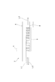
- FIG. 1 schematically shows an FBG strain sensor 1 according to Embodiment 1 of the present invention.
- the FBG strain sensor 1 is a sensor that measures strain generated in the measurement target W using an optical fiber 2, and light emitted from a light source (not shown) is incident from one end side of the optical fiber 2.
- the optical fiber 2 has an FBG (fiber Bragg grating) 3 that reflects light having a specific wavelength called a Bragg wavelength with respect to incident light from the light source. Arranged on the side.
- FBG fiber Bragg grating
- the optical fiber 2 is formed of quartz glass or the like, and includes a core 4 through which incident light L1 from a light source (not shown) propagates, and a cladding 5 that covers the outer periphery of the core 4. ing.
- the FBG 3 is a diffraction grating in which the refractive index of the core 4 is changed by a length period ⁇ along the axial direction, that is, a grating period ⁇ .
- the FBG 3 reflects only light having a Bragg wavelength with respect to the incident light L1 as reflected light L2. The remaining light is transmitted as transmitted light L3.
- the length period ⁇ in the FBG 3 is one of the elements that define the wavelength (Bragg wavelength) of the reflected light L2, and when an axial distortion occurs in the FBG 3 and the grating period ⁇ is changed, The Bragg wavelength also changes. That is, the strain amount of the FBG 3 can be measured based on the amount of change of the Bragg wavelength before and after the occurrence of strain, specifically, the shift amount of the center wavelength of the reflected light L2.
- the FBG 3 is formed by irradiating the core 4 of the optical fiber 2 with ultraviolet rays or the like.
- the FBG strain sensor 1 includes a flat plate-shaped temperature compensation member 11 provided between the optical fiber 2 and the part to be measured W.
- the optical fiber 2 passes through the temperature compensation member 11.
- the temperature compensation member 11 is formed in a rectangular shape with the direction indicated by the arrow A in FIG. 1 as the longitudinal direction, and the optical fiber 2 is fixed to the upper surface 11a, which is one surface thereof, and the other surface is A certain lower surface 11b side can be fixed to the part to be measured W. Further, the temperature compensation member 11 is arranged so that the longitudinal direction (see arrow A) and the longitudinal direction of the optical fiber 2 are along each other, and the FBG 3 is located at substantially the center of the upper surface 11a of the temperature compensation member 11. ing.
- the optical fiber 2 and the upper surface 11a of the temperature compensation member 11 are fixed by the adhesive 12 over the entire surface where they abut.
- the lower surface 11b of the temperature compensation member 11 is fixed to the upper surface Wa of the part to be measured W by the adhesive 13 at two locations along the longitudinal direction. Therefore, when distortion occurs in the measurement target W in the direction indicated by the arrow A, the distortion is applied to the temperature compensation member 11 via the adhesive 13 at two locations. Further, since the optical fiber 2 is entirely bonded to the upper surface 11a of the temperature compensation member 11, the strain applied to the temperature compensation member 11 from the measurement target portion W is directly applied to the FBG 3. ing.
- the pair of adhesives 13 provided on the lower surface 11b of the temperature compensation member 11 are arranged such that the distance d1 is equal to or longer than the length d2 of the FBG 3, and the FBG 3 is attached to the upper surface 11a. It arrange
- the temperature compensation member 11 is made of glass having a coefficient of thermal expansion of zero, so that the temperature compensation member 11 does not expand due to changes in the ambient temperature.
- the optical fiber 2 has a positive coefficient of thermal expansion, and is expanded and contracted by thermal expansion accompanying a change in ambient temperature.
- the Bragg wavelength that is the wavelength of the reflected light L2 from the FBG 3 is defined by the grating period ⁇ of the FBG 3. Therefore, when the optical fiber 2 expands and contracts according to the ambient temperature, the grating period ⁇ of the FBG 3 also changes accordingly, so that the Bragg wavelength changes.
- the coefficient of thermal expansion is not limited to the case where the coefficient of thermal expansion is almost zero as in the case of zero thermal expansion glass, but refers to the case where the coefficient of thermal expansion is almost zero. Including a case where is not more than ⁇ 1 ⁇ 10 ⁇ 6 / ° C.
- the optical fiber 2 is fixed to the temperature compensation member 11 having a thermal expansion coefficient of zero by the adhesive 12 over the entire surface where the optical fiber 2 abuts, the expansion and contraction of the FBG 3 is constrained by the temperature compensation member 11. It has become. That is, since the thermal expansion of the FBG 3 according to the ambient temperature is suppressed by the temperature compensation member 11 that does not cause thermal expansion, only the strain of the part to be measured W is applied to the FBG 3 regardless of the ambient temperature. It has become.
- the optical fiber 2 in the first embodiment has been described as having a positive thermal expansion coefficient, the effect of suppressing the thermal expansion of the FBG 3 by the temperature compensation member 11 is that the optical fiber 2 has a negative thermal expansion coefficient. The same applies to the case of having. Further, the coefficient of thermal expansion of the temperature compensation member 11 can be made zero by adjusting manufacturing conditions such as preparation of glass components as materials.
- the FBG strain sensor 1 is fixed to the upper surface Wa of the part W to be measured by the adhesive 13 applied to both ends of the lower surface 11 b of the temperature compensation member 11.
- a light source (not shown) is connected to one end side of the optical fiber 2.
- a measuring instrument (not shown) to which the reflected light L2 from the FBG 3 (see FIG. 2) is input is connected to one end side of the optical fiber 2. This measuring device calculates the amount of distortion of the portion to be measured W based on the amount of change in the reflected light L2 before and after the occurrence of strain at the portion to be measured W, that is, the amount of shift of the Bragg wavelength.
- the FBG strain sensor 1 When the FBG strain sensor 1 is fixed to the measurement target W, incident light L1 is incident on the optical fiber 2 from a light source (not shown).
- the FBG 3 reflects Bragg wavelength light as reflected light L2 with respect to the incident light L1, and transmits the remaining light as transmitted light L3 (see FIG. 2).
- the agent 12 is sequentially applied to the FBG 3.
- the strain of the part to be measured W is applied to the FBG 3 and the FBG 3 expands, the grating period ⁇ (see FIG. 2) of the FBG 3 also expands, so the wavelength of the reflected light L2 (Bragg wavelength) also changes.
- the optical fiber 2 since the optical fiber 2 has a positive coefficient of thermal expansion, the optical fiber 2 tends to expand in the direction along the longitudinal direction A by thermal expansion corresponding to the ambient temperature at the time of strain measurement.
- the optical fiber 2 since the optical fiber 2 is fixed to the temperature compensation member 11 having a thermal expansion coefficient of zero on the entire surface in contact with the temperature compensation member 11, and the expansion and contraction of the FBG 3 is restricted by the temperature compensation member 11, the extension of the FBG 3 is performed. Is suppressed. Therefore, the FBG 3 is in a state in which temperature compensation is performed with respect to the ambient temperature, that is, the Bragg wavelength shift due to thermal expansion of the FBG 3 does not occur, and the Bragg wavelength is shifted only by the strain of the measurement target W. Therefore, the strain amount of the part W to be measured is measured without error due to the ambient temperature.
- the temperature compensation member 11 is provided between the part to be measured W and the FBG 3 of the optical fiber 2, strain generated in the part to be measured W is applied to the FBG 3 via the temperature compensation member 11. Since the temperature compensation member 11 is formed of a material having a coefficient of thermal expansion of zero, it does not thermally expand according to the ambient temperature when measuring the strain amount. Since the FBG 3 is fixed to such a temperature compensation member 11, the FBG 3 is constrained by the temperature compensation member 11, and the thermal expansion of the FBG 3 according to the ambient temperature is suppressed.
- the FBG strain sensor 1 can perform temperature compensation with a simple configuration without increasing the size of the entire sensor.
- the temperature compensation member 11 is a flat plate member, the configuration of the FBG strain sensor 1 becomes simpler and the size in the height direction can be suppressed, so that the entire sensor can be further downsized.
- Embodiment 2 an FBG strain sensor according to Embodiment 2 of the present invention will be described.
- the FBG strain sensor according to the second embodiment is applied as a vehicle sensor that detects a vehicle collision.
- the same reference numerals as those shown in FIGS. 1 and 2 are the same or similar components, and thus detailed description thereof is omitted.
- the vehicle sensor 21 detects a collision of the vehicle 30 in order to operate a device such as an air bag, for example.
- a portion to be measured W is provided at a plurality of locations such as both sides of the rear portion.
- a single optical fiber 2 is routed inside the body 31 so as to pass through each measured portion W, and the optical fiber 2 is installed at a plurality of locations corresponding to each measured portion W. It has FBG3 similar to the form 1.
- Each FBG 3 is fixed to a temperature compensation member 11 attached to the part W to be measured, and the FBG 3 and the temperature compensation member 11 form a sensor unit 22.
- Each sensor unit 22 has the same configuration as the FBG strain sensor 1 shown in FIG. That is, the vehicle sensor 21 is obtained by installing the FBG strain sensor 1 according to the first embodiment on each measured portion W of the body 31 and connecting them via a single optical fiber 2.
- a light source (not shown) and a detection unit (not shown) for detecting a change in Bragg wavelength are connected to one end of the optical fiber 2. Further, the detection unit is electrically connected to a control unit (not shown) of the vehicle 30 and can output a detection result of the Bragg wavelength to the control unit.
- the control unit determines that the vehicle 30 has collided and activates the airbag or the like.
- temperature compensation is performed with respect to the ambient temperature as in the FBG strain sensor 1 in the first embodiment, so that malfunction does not occur due to a temperature change in the vehicle 30.
- the vehicle 30 can be compensated for temperature only by drawing one optical fiber 2 into the vehicle 30. Therefore, the vehicle sensor 21 can be constructed with a simple configuration. In addition, each sensor unit can be reduced in size as in the first embodiment, and therefore can be easily installed in a narrow place in the vehicle 30.
- Each sensor in the first and second embodiments is configured to measure the strain amount of the measurement target W based on the change amount of the wavelength of the reflected light L2 from the FBG 3, but is not limited to this configuration. It is also possible to measure the amount of strain based on the amount of change in the wavelength of the transmitted light L3. Since the transmitted light L3 is obtained by removing the reflected light L2 from the incident light L1 incident on the optical fiber 2, the amount of shift of the Bragg wavelength can be obtained from the transmitted light L3. Therefore, even when the strain amount is measured based on the transmitted light L3, the same effect as in the first and second embodiments can be obtained.
- a light source is connected to one end side of the optical fiber 2, and a measuring instrument is connected to the other end side.
- the shape of the temperature compensation member 11 is not limited. What is necessary is just to be able to apply the distortion amount of the to-be-measured part W to FBG3, for example, it can be set as polygonal shapes, such as a square which does not have a longitudinal direction, circular shapes, etc.
- the temperature compensation member is not limited to a plate-like member, and may be a cylindrical member or a rod-like member, for example. Even in this case, strain measurement and temperature compensation can be performed on a single measurement target W with a single FBG, so that temperature compensation can be performed with a simple configuration without increasing the size of the entire sensor. It becomes.
- the portion to be measured W in Embodiment 1 is shown in FIG. 1 as a rectangular member, the shape of the portion to be measured W is not limited, and the FBG strain sensor according to the present invention is the portion to be measured W. It is not limited to including.
- the present invention relates to an FBG strain sensor that can be fixed to a part to be measured, and may be an FBG strain sensor in a state before being fixed to the part to be measured.
- the temperature compensation member 11 in the first and second embodiments is fixed to the measured portion W by the pair of adhesives 13 applied to both ends thereof, but the temperature compensation member 11 and the measured portion W are bonded to each other. It is not limited to performing by these, and fixing these in two places used as the both ends of a temperature compensation member. What is necessary is just to be able to fix so that the distortion which arises in the to-be-measured part W is applied to the temperature compensation member 11, for example, using other fixing methods, such as welding, or fixing in two or more places including parts other than both ends. Is possible.
Landscapes
- Physics & Mathematics (AREA)
- General Physics & Mathematics (AREA)
- Length Measuring Devices By Optical Means (AREA)
- Optical Transform (AREA)
Abstract
センサ全体を大型化することなく、簡単な構成で温度補償を行うことを実現したFBGひずみセンサを提供することを目的とする。 FBGひずみセンサ1は、FBG3が形成された光ファイバ2と、光ファイバ2を被測定部Wに固定するための温度補償部材11とを備えている。光ファイバ2と温度補償部材11とは、これらが当接する全面において接着剤12によって固定されている。一方、温度補償部材11と被測定部Wとは、温度補償部材11の両端部において接着剤13によって固定されている。温度補償部材11は、熱膨張係数がゼロである材料から形成されており、FBG3の伸縮が温度補償部材11によって拘束されている。したがって、雰囲気温度に応じたFBG3の熱膨張は温度補償部材11によって抑制された状態となっており、被測定部Wに生じるひずみのみがFBG3に印加される。
Description
この発明は、被測定物のひずみ量を測定するFBGひずみセンサに係り、特に、測定時の雰囲気温度に応じた温度補償を行うための構成に関する。
近年、ひずみ量を測定するひずみセンサとして、FBG(ファイバ・ブラッグ・グレーティング)を用いたFBGひずみセンサが用いられる。FBGとは、光ファイバのコアの屈折率を軸方向に沿った所定の長さ周期(グレーティング周期)で変化させた回折格子であって、光ファイバへの入射光に対し、グレーティング周期に応じた特定の波長(ブラッグ波長)の光のみを反射し、残りの光を透過するという特性を有している。FBGにひずみが発生するとグレーティング周期が変化し、それに伴ってブラッグ波長も変化するため、ブラッグ波長の変化量に基づいてひずみ量を測定することが可能となる。ここで、光ファイバは、ひずみ量の測定時における周囲温度である雰囲気温度に応じて熱膨張し、それに応じてグレーティング周期も変化するため、FBGのブラッグ波長は、雰囲気温度によって変化するという特性も有している。したがって、被測定物の正確なひずみ量を測定するためには、雰囲気温度に応じた温度補償を行うことが必要となる。
例えば特許文献1には、検出素子部として形成された2つのFBGを用いて温度補償を行う光ファイバセンサが開示されている。これによれば、FBGの一方はひずみ量測定用として、被測定物である鋼索に固定される液晶ポリマ基板に対して密着するように設けられている。また、FBGの他方は温度補償用として、液晶ポリマ基板に対して弛んだ状態で設けられている。ひずみ量測定用FBGのブラッグ波長は、液晶ポリマ基板を介して印加される鋼索のひずみ量と、雰囲気温度に応じた光ファイバの熱膨張量とに起因して変化する。一方、弛んだ状態の温度補償用FBGには鋼索のひずみ量が印加されないため、そのブラッグ波長は、雰囲気温度に応じた光ファイバの熱膨張量に起因して変化する。すなわち、特許文献1に記載のセンサは、ひずみ量測定用FBGのブラッグ波長の変化量から温度補償用FBGのブラッグ波長の変化量を減算することによって温度補償を行い、鋼索のひずみ量を測定するものである。尚、これらの2つのFBGは直列または並列に配置可能となっており、直列に配置する場合、2つのFBGが一本の光ファイバに形成される。一方、FBGを並列に配置する場合は2本の光ファイバ、すなわち、ひずみ量測定用FBGが形成された光ファイバと、温度補償用FBGが形成された光ファイバとが液晶ポリマ基板に設けられる。
しかしながら、特許文献1に記載の光ファイバセンサは、ひずみ量測定用と温度補償用との2つのFBGを必要とするため、センサ全体を小型化すること、またはセンサ全体の構成を簡単にすることが困難であるという問題点を有している。具体的には、特許文献1に記載の光ファイバセンサにおいて2つのFBGを直列に配置する場合、FBGが配置される部位の軸方向に沿った長さ寸法は必然的に大きくなるため、センサ全体を小型化することが困難となる。また、2つのFBGを並列に配置する場合、2本の光ファイバが液晶ポリマ基板に設けられるため、入射光の供給や反射光の検出を2本の光ファイバに対してそれぞれ行うことが必要となり、センサ全体の構成が複雑になる。
この発明は、このような問題点を解決するためになされたもので、センサ全体を大型化することなく、簡単な構成で温度補償を行うことを実現したFBGひずみセンサを提供することを目的とする。
この発明に係るFBGひずみセンサは、被測定部から印加されるひずみ量に応じて、入射光に対する反射光の波長と入射光に対する透過光の波長とを変化させるFBGを有する光ファイバを備え、反射光の波長の変化量または透過光の波長の変化量に基づいて、被測定部のひずみ量を測定するFBGひずみセンサであって、一方の面にFBGが固定され、他方の面を被測定部に固定可能な温度補償部材をさらに備え、温度補償部材は、熱膨張係数がゼロである材料から形成される。
また、上記FBGひずみセンサは、車両の衝突を検知する車両用センサに適用することが可能である。この場合の車両用センサは、車両が複数の被測定部を有し、光ファイバが複数の被測定部に設けられる複数のFBGを有し、複数の被測定部の少なくとも1つから対応するFBGに印加されるひずみ量に基づいて、車両の衝突を検知する。
この発明によれば、FBGを用いたひずみセンサにおいて、センサ全体を大型化することなく、簡単な構成で温度補償を行うことが可能となる。
以下に、この発明の実施の形態について添付図に基づいて説明する。
実施の形態1.
図1に、この発明の実施の形態1に係るFBGひずみセンサ1を概略的に示す。FBGひずみセンサ1は、光ファイバ2を利用して被測定部Wに発生するひずみを測定するセンサであって、光ファイバ2の一端側からは、図示しない光源から発せられる光が入射される。また、光ファイバ2は、光源からの入射光に対してブラッグ波長と呼ばれる特定の波長の光を反射するFBG(ファイバ・ブラッグ・グレーティング)3を有しており、FBG3が被測定部Wの上方側に配置されている。
実施の形態1.
図1に、この発明の実施の形態1に係るFBGひずみセンサ1を概略的に示す。FBGひずみセンサ1は、光ファイバ2を利用して被測定部Wに発生するひずみを測定するセンサであって、光ファイバ2の一端側からは、図示しない光源から発せられる光が入射される。また、光ファイバ2は、光源からの入射光に対してブラッグ波長と呼ばれる特定の波長の光を反射するFBG(ファイバ・ブラッグ・グレーティング)3を有しており、FBG3が被測定部Wの上方側に配置されている。
ここで、図2を参照すると、光ファイバ2は石英ガラス等から形成されており、図示しない光源からの入射光L1が伝播するコア4と、コア4の外周部を覆うクラッド5とから構成されている。FBG3は、コア4の屈折率を軸方向に沿った長さ周期Λ、すなわちグレーティング周期Λで変化させた回折格子であり、入射光L1に対してブラッグ波長の光のみを反射光L2として反射し、残りの光を透過光L3として透過させる。
また、FBG3における長さ周期Λは、反射光L2の波長(ブラッグ波長)を規定する要素の1つとなっており、FBG3に軸方向のひずみが発生してグレーティング周期Λが変化すると、それに伴ってブラッグ波長も変化する。すなわち、ひずみの発生前後におけるブラッグ波長の変化量、具体的には、反射光L2の中心波長のシフト量に基づいて、FBG3のひずみ量を測定可能となっている。尚、一例として、FBG3は、光ファイバ2のコア4に紫外線等を照射することによって形成される。
図1に戻って、FBGひずみセンサ1は、光ファイバ2と被測定部Wとの間に設けられた平板状の温度補償部材11を備えており、光ファイバ2は、温度補償部材11を介して被測定部Wに固定される。温度補償部材11は、図1の矢印Aで示される方向を長手方向とする長方形に形成されており、その一方の面である上部表面11aに光ファイバ2が固定されるとともに、他方の面である下部表面11b側を被測定部Wに固定可能となっている。また、温度補償部材11は、その長手方向(矢印A参照)と光ファイバ2の長手方向とが互いに沿うように配置されており、温度補償部材11の上部表面11aのほぼ中央にFBG3が位置している。
光ファイバ2と温度補償部材11の上部表面11aとは、これらが当接する全面で接着剤12によって固定されている。一方、温度補償部材11の下部表面11bは、被測定部Wの上部表面Waに対し、長手方向に沿った両端部の二箇所で接着剤13によって固定されている。したがって、矢印Aで示す方向において被測定部Wにひずみが発生すると、そのひずみが二箇所の接着剤13を介して温度補償部材11に印加されるようになっている。また、温度補償部材11の上部表面11aには光ファイバ2が全面的に接着されているため、被測定部Wから温度補償部材11に印加されたひずみが、そのままFBG3に印加されるようになっている。
尚、温度補償部材11の下部表面11bに設けられた一対の接着剤13は、それらの間隔d1がFBG3の長さd2以上となるように配置されており、FBG3は、上部表面11aにおいて接着剤13同士の間隔d1の内側に対応する部位に配置されている。また、これらの接着剤13は、被測定部Wに対して温度補償部材11を固定可能とするものであり、FBGひずみセンサ1における一対の取り付け部材を構成している。
温度補償部材11は、熱膨張係数がゼロであるガラスを材料として形成されており、雰囲気温度の変化に伴う温度補償部材11の熱膨張が生じないようになっている。一方、光ファイバ2は正の熱膨張係数を有しており、雰囲気温度の変化に伴う熱膨張によって伸縮するようになっている。ここで、図2を用いて上述したように、FBG3からの反射光L2の波長であるブラッグ波長は、FBG3のグレーティング周期Λによって規定される。したがって、光ファイバ2が雰囲気温度に応じて伸縮すると、それに伴ってFBG3のグレーティング周期Λも変化するため、ブラッグ波長が変化することになる。尚、熱膨張係数がゼロであるとは、零熱膨張ガラスのように熱膨張係数が完全にゼロである場合に限らず、熱膨張係数がほとんどゼロである場合を指し、例えば、熱膨張係数が±1×10⁻⁶/℃以下である場合を含む。
しかしながら、光ファイバ2は、熱膨張係数がゼロである温度補償部材11に対し、これらが当接する全面で接着剤12によって固定されているため、FBG3の伸縮が温度補償部材11によって拘束された状態となっている。すなわち、雰囲気温度に応じたFBG3の熱膨張は、熱膨張が生じない温度補償部材11によって抑制されているため、FBG3には、雰囲気温度にかかわらず被測定部Wのひずみのみが印加される状態となっている。尚、この実施の形態1における光ファイバ2は正の熱膨張係数を有するものとして上述したが、温度補償部材11によってFBG3の熱膨張を抑制するという効果は、光ファイバ2が負の熱膨張係数を有している場合においても同様である。また、温度補償部材11の熱膨張係数は、例えば材料であるガラスの成分の調合等といった製造条件を調整することによってゼロとすることが可能となる。
次に、この発明の実施の形態1に係るFBGひずみセンサ1を用いて、被測定部Wに発生したひずみを測定する場合の動作について説明する。
図1に示すように、まず、温度補償部材11の下部表面11bにおける両端に塗布された接着剤13により、FBGひずみセンサ1が被測定部Wの上部表面Waに固定される。次いで、光ファイバ2の一端側には、図示しない光源が接続される。また、光ファイバ2の一端側には、光源の他に、FBG3からの反射光L2(図2参照)が入力される図示しない測定器が接続される。この測定器は、被測定部Wでのひずみの発生前後における反射光L2の変化量、すなわちブラッグ波長のシフト量に基づいて、被測定部Wのひずみ量を算出するものである。
図1に示すように、まず、温度補償部材11の下部表面11bにおける両端に塗布された接着剤13により、FBGひずみセンサ1が被測定部Wの上部表面Waに固定される。次いで、光ファイバ2の一端側には、図示しない光源が接続される。また、光ファイバ2の一端側には、光源の他に、FBG3からの反射光L2(図2参照)が入力される図示しない測定器が接続される。この測定器は、被測定部Wでのひずみの発生前後における反射光L2の変化量、すなわちブラッグ波長のシフト量に基づいて、被測定部Wのひずみ量を算出するものである。
被測定部WにFBGひずみセンサ1が固定されると、図示しない光源から光ファイバ2に入射光L1が入射される。入射光L1に対し、FBG3はブラッグ波長の光を反射光L2として反射し、残りの光を透過光L3として透過する(図2参照)。このような状態で、図1の矢印B1、B2で示されるように被測定部Wに軸方向Aに沿ったひずみが発生すると、そのひずみが二箇所の接着剤13、温度補償部材11、接着剤12を順次介してFBG3に印加される。被測定部WのひずみがFBG3に印加されてFBG3が伸張すると、FBG3のグレーティング周期Λ(図2参照)も伸張するため、反射光L2の波長(ブラッグ波長)も変化する。
ここで、光ファイバ2は正の熱膨張係数を有しているため、ひずみの測定時における雰囲気温度に応じた熱膨張により、光ファイバ2は長手方向Aに沿った方向に伸張しようとする。しかしながら、光ファイバ2は、熱膨張係数がゼロである温度補償部材11に対し、これらが当接する全面で固定されており、FBG3の伸縮が温度補償部材11によって拘束されているため、FBG3の伸張が抑制されている。したがって、FBG3は、雰囲気温度に対する温度補償が行われた状態、すなわちFBG3が熱膨張することに起因するブラッグ波長のシフトが生じず、被測定部Wのひずみのみによってブラッグ波長がシフトする状態となっており、被測定部Wのひずみ量が雰囲気温度による誤差なく測定される。
このように、被測定部Wと光ファイバ2のFBG3との間に温度補償部材11を設けたので、被測定部Wに生じるひずみが温度補償部材11を介してFBG3に印加される。温度補償部材11は熱膨張係数がゼロである材料から形成されているため、ひずみ量の測定時における雰囲気温度に応じて熱膨張することがない。このような温度補償部材11にFBG3を固定したので、FBG3が温度補償部材11に拘束された状態となり、雰囲気温度に応じたFBG3の熱膨張が抑制される。FBG3には、雰囲気温度にかかわらず被測定部Wのひずみのみが印加される状態となっているため、一箇所の被測定部Wに対してひずみの測定と温度補償とを行うために、複数のFBGを用いることや複数の光ファイバを用いること、すなわちひずみ量測定用FBG及び温度補償用FBGを用いることを必要としない。したがって、FBGひずみセンサ1において、センサ全体を大型化することなく、簡単な構成で温度補償を行うことが可能となる。
また、温度補償部材11は平板状の部材としたので、FBGひずみセンサ1の構成がより簡単になるとともに高さ方向の寸法が抑えられるため、センサ全体をより小型化することが可能となる。
実施の形態2.
次に、この発明の実施の形態2に係るFBGひずみセンサについて説明する。この実施の形態2に係るFBGひずみセンサは、車両の衝突を検知する車両用センサとして適用されたものである。尚、以下に説明する実施の形態において、図1、2に示される符号と同一の符号は同一または同様な構成要素であるので、その詳細な説明は省略する。
図3に示すように、車両用センサ21は、例えばエアバッグ等の機器を作動させるために車両30の衝突を検知するものであって、車両30は、例えばボディー31の前部、中間部及び後部における両側等、複数の箇所に被測定部Wを有している。
次に、この発明の実施の形態2に係るFBGひずみセンサについて説明する。この実施の形態2に係るFBGひずみセンサは、車両の衝突を検知する車両用センサとして適用されたものである。尚、以下に説明する実施の形態において、図1、2に示される符号と同一の符号は同一または同様な構成要素であるので、その詳細な説明は省略する。
図3に示すように、車両用センサ21は、例えばエアバッグ等の機器を作動させるために車両30の衝突を検知するものであって、車両30は、例えばボディー31の前部、中間部及び後部における両側等、複数の箇所に被測定部Wを有している。
また、ボディー31の内部には、各被測定部Wを通るように一本の光ファイバ2が引き回されており、光ファイバ2は、各被測定部Wに対応する複数の箇所に、実施の形態1と同様のFBG3を有している。各FBG3は、被測定部Wに張り付けられた温度補償部材11に固定されており、FBG3と温度補償部材11とがセンサ部22を形成している。各センサ部22は、図1に示されるFBGひずみセンサ1と同様の構成を有するものである。すなわち、車両用センサ21は、実施の形態1におけるFBGひずみセンサ1をボディー31の各被測定部Wにそれぞれ設置し、それらを一本の光ファイバ2を介して接続したものである。尚、光ファイバ2の一端には、図示しない光源と、ブラッグ波長の変化を検知する図示しない検知部とが接続されている。また、検知部は、車両30の図示しない制御部に電気的に接続されており、制御部に対してブラッグ波長の検知結果を出力可能となっている。
以上のように構成される車両用センサ21において、車両30が衝突を起こして各被測定部Wの少なくとも一箇所にひずみが生じると、ひずんだ箇所に対応するFBG3におけるブラッグ波長の変化が検知される。図示しない制御部は、ブラッグ波長が変化したことを示す信号が入力されると、車両30が衝突したと判定してエアバッグ等を作動させる。尚、車両用センサ21では、実施の形態1におけるFBGひずみセンサ1と同様に、雰囲気温度に対する温度補償が行われるため、車両30内の温度変化に起因して誤作動を起こすこともない。
このように、FBG3及び温度補償部材11を複数として車両30内の複数の被測定部Wに配置したので、一本の光ファイバ2を車両30内に引き回すだけで、温度補償を行いつつ車両30の衝突を検知することが可能となるため、簡単な構成で車両用センサ21を構築することができる。また、各センサ部は、実施の形態1と同様に小型化することが可能であるため、車両30内の狭い場所にも容易に設置することができる。
実施の形態1、2における各センサは、FBG3からの反射光L2の波長の変化量に基づいて被測定部Wのひずみ量を測定するように構成されたが、この構成に限定されるものではなく、透過光L3の波長の変化量に基づいてひずみ量を測定することも可能である。透過光L3は、光ファイバ2に入射される入射光L1から反射光L2を除いたものとなるため、透過光L3からブラッグ波長のシフト量を求めることも可能となっている。したがって、透過光L3に基づいてひずみ量を測定するように構成した場合においても、実施の形態1、2と同様の効果を得ることができる。尚、被測定部Wのひずみ量を透過光L3に基づいて測定する場合には光ファイバ2の一端側に光源が接続され、他端側に測定器が接続される。
実施の形態1、2における温度補償部材11は、図1の矢印Aで示される方向を長手方向とする長方形に形成されているが、温度補償部材11の形状を限定するものではない。被測定部Wのひずみ量をFBG3に印加可能であればよく、例えば、長手方向を有さない正方形等の多角形や円形等に形成とすることが可能である。また、温度補償部材は板状の部材に限定されるものでもなく、例えば筒状の部材や棒状の部材とすることも可能である。この場合においても、一箇所の被測定部Wに対するひずみ測定及び温度補償を単一のFBGで行うことができるため、センサ全体を大型化することなく、簡単な構成で温度補償を行うことが可能となる。
実施の形態1における被測定部Wは矩形の部材として図1に示されているが、被測定部Wの形状を限定するものではなく、また、本発明に係るFBGひずみセンサが被測定部Wを含むことに限定するものでもない。本発明は、被測定部に固定可能なFBGひずみセンサに関するものであり、被測定部に固定される前の状態にあるFBGひずみセンサであってもよい。
実施の形態1、2における温度補償部材11は、その両端部に塗布された一対の接着剤13によって被測定部Wに固定されたが、温度補償部材11と被測定部Wとの固定を接着によって行うこと、及びこれらの固定を温度補償部材の両端部となる二箇所で行うことに限定するものではない。被測定部Wに生じるひずみが温度補償部材11に印加されるように固定できればよく、例えば溶接等の他の固定方法を用いることや、両端部以外の部位を含む二箇所以上で固定することも可能である。
Claims (6)
- 被測定部から印加されるひずみ量に応じて、入射光に対する反射光の波長と前記入射光に対する透過光の波長とを変化させるFBGを有する光ファイバを備え、
前記反射光の波長の変化量または前記透過光の波長の変化量に基づいて、前記被測定部の前記ひずみ量を測定するFBGひずみセンサであって、
一方の面に前記FBGが固定され、他方の面を前記被測定部に固定可能な温度補償部材をさらに備え、
前記温度補償部材は、熱膨張係数がゼロである材料から形成されるFBGひずみセンサ。 - 前記温度補償部材は、平板状の部材である請求項1に記載のFBGひずみセンサ。
- 前記被測定部に対して前記温度補償部材を固定可能な一対の取り付け部材をさらに備え、
前記一対の取り付け部材は、前記FBGの長さ以上の間隔をおいて、前記温度補償部材の前記他方の面に配置されており、
前記FBGは、前記温度補償部材の前記一方の面において前記間隔の内側に対応する部位に配置される請求項1または2に記載のFBGひずみセンサ。 - 前記光ファイバ及び前記温度補償部材は長手方向をそれぞれ有し、
前記温度補償部材の長手方向と前記光ファイバの長手方向とが互いに沿うように配置される請求項1~3のいずれか一項に記載のFBGひずみセンサ。 - 前記一対の取り付け部材は、前記温度補償部材の両端部に配置される請求項3または4のいずれか一項に記載のFBGひずみセンサ。
- 請求項1~5のいずれか一項に記載のFBGひずみセンサを用いて車両の衝突を検知する車両用センサであって、
前記車両は複数の被測定部を有し、
前記光ファイバは前記複数の被測定部に設けられる複数のFBGを有し、
前記複数の被測定部の少なくとも1つから対応する前記FBGに印加されるひずみ量に基づいて、前記車両の衝突を検知する車両用センサ。
Applications Claiming Priority (2)
| Application Number | Priority Date | Filing Date | Title |
|---|---|---|---|
| JP2011-092741 | 2011-04-19 | ||
| JP2011092741A JP2012225729A (ja) | 2011-04-19 | 2011-04-19 | Fbgひずみセンサ |
Publications (1)
| Publication Number | Publication Date |
|---|---|
| WO2012144272A1 true WO2012144272A1 (ja) | 2012-10-26 |
Family
ID=47041394
Family Applications (1)
| Application Number | Title | Priority Date | Filing Date |
|---|---|---|---|
| PCT/JP2012/054647 WO2012144272A1 (ja) | 2011-04-19 | 2012-02-24 | Fbgひずみセンサ |
Country Status (2)
| Country | Link |
|---|---|
| JP (1) | JP2012225729A (ja) |
| WO (1) | WO2012144272A1 (ja) |
Cited By (3)
| Publication number | Priority date | Publication date | Assignee | Title |
|---|---|---|---|---|
| CN106289088A (zh) * | 2016-07-27 | 2017-01-04 | 四川大学 | 应用于工程材料的补偿应变测试方法 |
| CN111811408A (zh) * | 2020-07-06 | 2020-10-23 | 天津求实飞博科技有限公司 | 一种应变系数自适应矿用围岩光纤位移传感器 |
| CN116067298A (zh) * | 2023-04-06 | 2023-05-05 | 山东省科学院激光研究所 | 一种光纤应变传感器结构 |
Families Citing this family (3)
| Publication number | Priority date | Publication date | Assignee | Title |
|---|---|---|---|---|
| KR101657776B1 (ko) * | 2014-10-15 | 2016-10-04 | (주)제이엠솔루션 | 자동차 내부 통신망을 연동한 차량용 충격 센싱 장치 |
| EP3425343A4 (en) * | 2016-03-01 | 2019-04-17 | Cmiws Co., Ltd. | FIBER OPTIC SENSOR |
| CN109373922A (zh) * | 2018-11-16 | 2019-02-22 | 中国铁路广州局集团有限公司 | 一种高铁站房光纤光栅温度补偿应变传感器 |
Citations (7)
| Publication number | Priority date | Publication date | Assignee | Title |
|---|---|---|---|---|
| JPH1073740A (ja) * | 1996-06-13 | 1998-03-17 | Corning Inc | 光学装置およびその製造方法 |
| JP2000111319A (ja) * | 1998-09-30 | 2000-04-18 | Ntt Advanced Technology Corp | 光ファイバセンサ |
| JP2004226546A (ja) * | 2003-01-21 | 2004-08-12 | Nippon Sheet Glass Co Ltd | 光ファイバ回折格子を用いた光学装置 |
| WO2005028995A1 (ja) * | 2003-09-17 | 2005-03-31 | Kyocera Corporation | Fbgセンシングシステム |
| JP2005214824A (ja) * | 2004-01-30 | 2005-08-11 | Denso Corp | 光ファイバセンサ装置 |
| JP2005321223A (ja) * | 2004-05-06 | 2005-11-17 | Kawasaki Heavy Ind Ltd | 構造体および損傷検知装置 |
| JP2009059582A (ja) * | 2007-08-31 | 2009-03-19 | Toyota Motor Corp | 二次電池の圧力検出装置 |
-
2011
- 2011-04-19 JP JP2011092741A patent/JP2012225729A/ja active Pending
-
2012
- 2012-02-24 WO PCT/JP2012/054647 patent/WO2012144272A1/ja active Application Filing
Patent Citations (7)
| Publication number | Priority date | Publication date | Assignee | Title |
|---|---|---|---|---|
| JPH1073740A (ja) * | 1996-06-13 | 1998-03-17 | Corning Inc | 光学装置およびその製造方法 |
| JP2000111319A (ja) * | 1998-09-30 | 2000-04-18 | Ntt Advanced Technology Corp | 光ファイバセンサ |
| JP2004226546A (ja) * | 2003-01-21 | 2004-08-12 | Nippon Sheet Glass Co Ltd | 光ファイバ回折格子を用いた光学装置 |
| WO2005028995A1 (ja) * | 2003-09-17 | 2005-03-31 | Kyocera Corporation | Fbgセンシングシステム |
| JP2005214824A (ja) * | 2004-01-30 | 2005-08-11 | Denso Corp | 光ファイバセンサ装置 |
| JP2005321223A (ja) * | 2004-05-06 | 2005-11-17 | Kawasaki Heavy Ind Ltd | 構造体および損傷検知装置 |
| JP2009059582A (ja) * | 2007-08-31 | 2009-03-19 | Toyota Motor Corp | 二次電池の圧力検出装置 |
Non-Patent Citations (1)
| Title |
|---|
| DU YANLIANG ET AL.: "A Novel Fiber Bragg Gating Temperature Compensated Strain Sensor", FIRST INTERNATIONAL CONFERENCE ON INTELLIGENT NETWORKS AND INTELLIGENT SYSTEMS, 2008., 21 November 2008 (2008-11-21), pages 569 - 572, XP031364342 * |
Cited By (5)
| Publication number | Priority date | Publication date | Assignee | Title |
|---|---|---|---|---|
| CN106289088A (zh) * | 2016-07-27 | 2017-01-04 | 四川大学 | 应用于工程材料的补偿应变测试方法 |
| CN111811408A (zh) * | 2020-07-06 | 2020-10-23 | 天津求实飞博科技有限公司 | 一种应变系数自适应矿用围岩光纤位移传感器 |
| CN111811408B (zh) * | 2020-07-06 | 2022-01-28 | 天津求实飞博科技有限公司 | 一种应变系数自适应矿用围岩光纤位移传感器 |
| CN116067298A (zh) * | 2023-04-06 | 2023-05-05 | 山东省科学院激光研究所 | 一种光纤应变传感器结构 |
| CN116067298B (zh) * | 2023-04-06 | 2023-06-09 | 山东省科学院激光研究所 | 一种光纤应变传感器结构 |
Also Published As
| Publication number | Publication date |
|---|---|
| JP2012225729A (ja) | 2012-11-15 |
Similar Documents
| Publication | Publication Date | Title |
|---|---|---|
| WO2012144272A1 (ja) | Fbgひずみセンサ | |
| US8879067B2 (en) | Wavelength dependent optical force sensing | |
| US7720324B2 (en) | Optical strain gauge strips | |
| ATE557270T1 (de) | Optische sensoren | |
| KR102414892B1 (ko) | 온도 측정용 기판 및 온도 측정 시스템 | |
| KR101203700B1 (ko) | 광섬유격자센서 및 이를 이용한 온도/스트레인 측정 시스템 | |
| KR100685186B1 (ko) | 광섬유 기반의 가속도계/경사계 | |
| JP6864375B2 (ja) | 光ファイバセンサ | |
| CN110121651B (zh) | 加速度检测设备和方法及检测至少两个空间方向上的加速度的设备 | |
| JP2012202684A (ja) | Fbgひずみセンサ | |
| JP2003222507A (ja) | 光ファイバセンサ及びそれを利用した歪み監視システム | |
| KR101504028B1 (ko) | 광섬유 격자 센서를 이용한 측정 장치 | |
| CZ28266U1 (cs) | Optovláknový senzor a sestava pro měření tvarových změn ochranné obálky jaderného reaktoru | |
| KR20140013605A (ko) | 온도보상형 광섬유 브래그 격자 모듈 | |
| US20060197012A1 (en) | Shear and pressure/transverse strain fiber grating sensors | |
| FR2909446B1 (fr) | Dispositif et procede de mesure des deformations mecaniques d'un profile | |
| GB2466929A (en) | Pressure sensor device comprising flexible diaphragm with integral optical sensor | |
| JP7047366B2 (ja) | 光ファイバセンサ | |
| JP2005127744A (ja) | Fbg式ひずみセンサ及びシステム | |
| JP2013221807A (ja) | 光ファイバ歪みセンサおよび光ファイバ温度センサ | |
| JP6736044B2 (ja) | 歪みセンサ及び歪みセンサの取付治具 | |
| JP2012202685A (ja) | Fbg振動センサ | |
| KR20190012921A (ko) | 광섬유 격자를 이용한 누수 및 침수 감지센서 | |
| JP2004264114A (ja) | Fbg式温度センサ及びこれを用いた温度計測システム | |
| JP2012202686A (ja) | Fbg振動センサ |
Legal Events
| Date | Code | Title | Description |
|---|---|---|---|
| 121 | Ep: the epo has been informed by wipo that ep was designated in this application |
Ref document number: 12774652 Country of ref document: EP Kind code of ref document: A1 |
|
| NENP | Non-entry into the national phase |
Ref country code: DE |
|
| 122 | Ep: pct application non-entry in european phase |
Ref document number: 12774652 Country of ref document: EP Kind code of ref document: A1 |