WO2012144106A1 - 導線溶接用チューブ及び接合導線の製造方法 - Google Patents
導線溶接用チューブ及び接合導線の製造方法 Download PDFInfo
- Publication number
- WO2012144106A1 WO2012144106A1 PCT/JP2011/078384 JP2011078384W WO2012144106A1 WO 2012144106 A1 WO2012144106 A1 WO 2012144106A1 JP 2011078384 W JP2011078384 W JP 2011078384W WO 2012144106 A1 WO2012144106 A1 WO 2012144106A1
- Authority
- WO
- WIPO (PCT)
- Prior art keywords
- conducting wire
- welding
- tube
- welding tube
- conducting
- Prior art date
- Legal status (The legal status is an assumption and is not a legal conclusion. Google has not performed a legal analysis and makes no representation as to the accuracy of the status listed.)
- Ceased
Links
Images


Classifications
-
- B—PERFORMING OPERATIONS; TRANSPORTING
- B23—MACHINE TOOLS; METAL-WORKING NOT OTHERWISE PROVIDED FOR
- B23K—SOLDERING OR UNSOLDERING; WELDING; CLADDING OR PLATING BY SOLDERING OR WELDING; CUTTING BY APPLYING HEAT LOCALLY, e.g. FLAME CUTTING; WORKING BY LASER BEAM
- B23K11/00—Resistance welding; Severing by resistance heating
- B23K11/02—Pressure butt welding
-
- B—PERFORMING OPERATIONS; TRANSPORTING
- B23—MACHINE TOOLS; METAL-WORKING NOT OTHERWISE PROVIDED FOR
- B23K—SOLDERING OR UNSOLDERING; WELDING; CLADDING OR PLATING BY SOLDERING OR WELDING; CUTTING BY APPLYING HEAT LOCALLY, e.g. FLAME CUTTING; WORKING BY LASER BEAM
- B23K11/00—Resistance welding; Severing by resistance heating
- B23K11/04—Flash butt welding
-
- B—PERFORMING OPERATIONS; TRANSPORTING
- B23—MACHINE TOOLS; METAL-WORKING NOT OTHERWISE PROVIDED FOR
- B23K—SOLDERING OR UNSOLDERING; WELDING; CLADDING OR PLATING BY SOLDERING OR WELDING; CUTTING BY APPLYING HEAT LOCALLY, e.g. FLAME CUTTING; WORKING BY LASER BEAM
- B23K11/00—Resistance welding; Severing by resistance heating
- B23K11/36—Auxiliary equipment
-
- B—PERFORMING OPERATIONS; TRANSPORTING
- B23—MACHINE TOOLS; METAL-WORKING NOT OTHERWISE PROVIDED FOR
- B23K—SOLDERING OR UNSOLDERING; WELDING; CLADDING OR PLATING BY SOLDERING OR WELDING; CUTTING BY APPLYING HEAT LOCALLY, e.g. FLAME CUTTING; WORKING BY LASER BEAM
- B23K37/00—Auxiliary devices or processes, not specially adapted for a procedure covered by only one of the other main groups of this subclass
- B23K37/06—Auxiliary devices or processes, not specially adapted for a procedure covered by only one of the other main groups of this subclass for positioning the molten material, e.g. confining it to a desired area
-
- B—PERFORMING OPERATIONS; TRANSPORTING
- B23—MACHINE TOOLS; METAL-WORKING NOT OTHERWISE PROVIDED FOR
- B23K—SOLDERING OR UNSOLDERING; WELDING; CLADDING OR PLATING BY SOLDERING OR WELDING; CUTTING BY APPLYING HEAT LOCALLY, e.g. FLAME CUTTING; WORKING BY LASER BEAM
- B23K2101/00—Articles made by soldering, welding or cutting
- B23K2101/32—Wires
Definitions
- the present invention relates to a technique for welding the ends of conductive wires.
- butt resistance welding such as upset welding may be employed to connect the ends of the conductive wires.
- welding is performed by bringing each conductive wire end portion into contact with each other and energizing and pressurizing in the butt direction.
- enlargement it is also called upsetting of the cross section of conducting wire arises by pressurization.
- the conductive wire continuously supplied is pushed out (drawn out) through a die (point jig) for pushing out a conductive wire in a crosshead die or the like in the manufacturing process of the electric wire.
- a die point jig
- the joining portion enlarged by welding is caught when passing through the die, and the conducting wire is broken.
- a method of suppressing the enlargement by performing welding in a state where the end portion of the conductive wire that is enlarged during welding is inserted into a ceramic tube such as steatite (MgOSiO 2 ) can be considered.
- the joint may be enlarged greatly, and it is difficult to effectively suppress the enlargement.
- an object of the present invention is to suppress the enlargement of the joint.
- a first aspect is a conductor welding tube that covers a welded portion in welding of ends of two conductors, and a hollow portion in which the two conductors can be inserted from both sides by a material having a Mohs hardness of 8 or more. It has a cylindrical shape.
- the second aspect is a conducting wire welding tube according to the first aspect, and is formed of ceramics.
- the third aspect is a wire welding tube according to the second aspect, and is formed of alumina-based ceramics.
- the fourth aspect is a wire welding tube according to the second or third aspect, and the porosity is set to 0%.
- a fifth aspect is a method of manufacturing a joined conductor in which ends of two conductors are welded to each other, and (a) the ends of the two conductors are connected to the conductor according to any one of the first to fourth aspects. Inserting into the hollow part of the welding tube and abutting, and (b) applying a voltage to the abutting part of the two conducting wires.
- the material having a Mohs hardness of 8 or more is formed into a cylindrical shape having a hollow portion into which two conducting wires can be inserted from both sides. By welding the portions, enlargement of the joint can be suppressed.
- the lead wire welding tube according to the second aspect is formed of ceramics, it has excellent heat resistance and is relatively easy to break and can improve removal workability after welding.
- the conductor welding tube according to the third aspect since it is formed of alumina-based ceramics, it has a good balance of hardness, heat resistance, and destructibility.
- the porosity is set to 0%, higher hardness can be obtained, and the enlargement of the joint in welding can be more effectively suppressed. it can.
- the ends of the two conductors are inserted into the hollow portion of the conductor welding tube, and the two conductors are welded by applying a voltage to the butted portion of the two conductors. ing.
- dissolved in the hollow part of the conducting wire welding tube in a conducting wire can be suppressed, and the enlargement of a junction part can be suppressed and a joining conducting wire can be manufactured.
- the conducting wire welding tube 10 according to the embodiment will be described (see FIG. 1).
- the conducting wire welding tube 10 is a member for suppressing the enlargement of the joint portion when the conducting wires 20 are butt-welded and resistance welded.
- the conducting wire 20 to be welded is a conducting wire obtained by rolling and compressing a single core wire or a plurality of core wires formed of aluminum (or aluminum alloy), copper (or copper alloy) or the like.
- the conductive wire 20 will be described as an example in which it is formed in a substantially circular shape in a cross-sectional view orthogonal to the extending direction.
- the conducting wire welding tube 10 is a member that covers the ends of the two conducting wires 20 to be welded during welding.
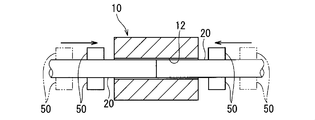
- This conducting wire welding tube 10 is formed in a cylindrical shape having a hollow portion 12 into which two conducting wires 20 can be inserted from both sides (see FIG. 1).
- the hollow portion 12 has a shape corresponding to the outer shape of the conducting wire 20 and has a substantially cylindrical space inside.
- the hollow portion 12 is formed slightly larger than the outer shape of the conducting wire 20. More specifically, the hollow portion 12 has a cross-sectional shape with a size (diameter) that allows the joint portion 122 formed by welding the two conducting wires 20 therein to pass through the drawing or extrusion die without disconnection. Is set.
- the hollow portion 12 is formed in an internal shape having a size equal to or smaller than the maximum size (diameter) into which the conductive wire 20 can be inserted and can pass through the die.
- the tube 10 for conducting wire welding is formed in a cylindrical shape as a whole.
- the conductor welding tube 10 is designed to have an axial dimension of 6 mm and an outer diameter of 6 mm (or 9 mm), and the inner diameter of the hollow portion 12 with respect to the conductor 20 having a diameter of 0.75 mm is 0.9 ⁇ 0. It can be designed and formed to 01 mm.
- the conducting wire welding tube 10 is formed of a ceramic material having a Mohs hardness of 8 or more.
- alumina (Al 2 O 3 ) -based ceramics is employed as the material for the conducting wire welding tube 10.
- the alumina-based ceramic employed as the material for the conducting wire welding tube 10 is formed with a porosity set to 0% by densification in order to improve heat resistance and hardness.
- the porosity of 0% includes an error range that inevitably occurs when forming 0% as a target value.
- the porosity means the ratio of the total volume of the pores in the volume
- the densification means the phenomenon that the ceramic powder compact is improved in density by heat treatment or sintering such as firing and the pores disappear.
- the conducting wire welding tube 10 is not limited to the one formed of the above materials. That is, as long as the tube for conducting wire welding is formed of a material having a Mohs hardness of 8 or more, a ceramic material other than alumina-based ceramics or a material having a porosity greater than 0% may be employed. However, it is preferable to employ a dense material having a low porosity.
- the conducting wire welding tube 10 is not limited to a cylindrical shape.
- the conducting wire welding tube may have a hollow portion 12 having a substantially cylindrical space, and may be formed in a polygonal shape in a cross-sectional view orthogonal to the penetrating direction of the hollow portion 12.
- each conducting wire 20 is inserted into the hollow portion 12 of the conducting wire welding tube 10 (see FIG. 2). More specifically, each conducting wire 20 is inserted into the hollow portion 12 from both sides of the conducting wire welding tube 10. That is, each conducting wire 20 is abutted in such a manner that the end faces are in contact with each other and the central axis is positioned substantially coaxially. Here, the abutting portion between the end portions is in a state of being pressed in the direction of contact.
- a voltage is applied to the butted portion (see FIG. 3). More specifically, a voltage is applied between the portions of each conducting wire 20 that extend from both sides of the conducting wire welding tube 10. Thereby, the butted portion of the conducting wire 20 generates heat and melts due to the contact resistance between the ends of the conducting wire 20 and the specific resistance of the conducting wire 20 (mainly the contact resistance between the ends of the conducting wire 20).
- the two conductors 20 are moved relatively close to each other in the butting direction, and the butted portion of the conducting wire 20 is further pressurized (see FIG. 3).
- This operation is performed in a state where the butted portion of the conducting wire 20 is located in the conducting wire welding tube 10.
- a melted portion hereinafter, melted portion
- the conducting wire 20 pushed into the hollow portion 12 a melted portion of the conducting wire 20 is spread to the outer peripheral side and pressed against the inner peripheral surface of the hollow portion 12. That is, the escape portion of the melted portion is restricted by the hollow portion 12 of the conductive wire welding tube 10 having high hardness, and the shape of the joint portion 122 to be formed is restricted.
- the melted portion of the conducting wire 20 is hatched.
- the joint portion 122 has a shape (substantially the same cross-sectional shape) along the shape of the hollow portion 12 of the conducting wire welding tube 10.
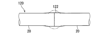
- the conductor welding tube 10 is removed from the outer peripheral position of the joint 122 (see FIG. 4). More specifically, the conductor welding tube 10 is destroyed and removed.
- the joining conducting wire 120 in which the ends of the two conducting wires 20 are welded is manufactured.
- matching part in case there is no conducting wire welding tube 10 is shown with the dashed-two dotted line.
- the above work may be performed by a dedicated device.
- a pair of electrode dies 50 that can hold the conductor 20 and are connected to a welding power source so as to be able to apply a voltage to the conductor 20 are supported so as to be relatively close to and away from each other. reference). That is, the two conductors 20 are respectively held by the electrode dies 50, the end portions thereof are inserted into the hollow portion 12 of the conductor welding tube 10, and a voltage is applied between the pair of electrode dies 50. The conductor 20 is moved by relative proximity and welding is performed.
- the welding of the conducting wire 20 may be performed by moving the conducting wire 20 in the butting direction while applying a voltage to the butted portion of the conducting wires 20, and as a process, a force is applied in the direction in which the conducting wire 20 is moved in the proximity. Then, a voltage may be applied to the abutting portion, or the application of the voltage and the proximity movement of the conducting wire 20 may be performed simultaneously.
- the upset welding has been described as an example, but the wire welding tube 10 can also be applied to butt resistance welding such as flash welding in which the joint portion 122 may be enlarged.
- a material having a Mohs hardness of 8 or more is formed into a cylindrical shape having a hollow portion 12 into which two conducting wires 20 can be inserted from both sides.
- the conducting wire welding tube 10 is formed of ceramics, it is excellent in heat resistance and relatively easy to break, and the removal workability after welding can be improved. Furthermore, since alumina ceramics are employed, it is excellent in hardness, heat resistance, and destructibility.
- the lead wire welding tube 10 is designed to have a porosity of 0%, it is possible to obtain higher hardness and to effectively suppress the enlargement of the joint 122 in welding.
- the end portions of the two conducting wires 20 are inserted into the hollow portion 12 of the conducting wire welding tube 10 and butted together. Welding is performed by applying a voltage to. Thereby, the expansion to the outer peripheral side of the part which melts in the hollow part 12 of the conducting wire welding tube 10 in the conducting wire 20 can be suppressed, and enlargement of the joining part 122 can be suppressed, and the joining conducting wire 120 can be manufactured. . Moreover, the dispersion
- Example> selection of the material of the conducting wire welding tube 10 will be described.
- the material was selected with the process capability index (Cpk value) of the outer diameter value and the breaking strength at the joint 122 of the conducting wire 20 as the evaluation object.
- the conductor 20 which is an aluminum wire (diameter 0.75 mm) is a welding target.
- the upper limit with respect to the target value 0.90 mm of the outer diameter in the joint part 122 is 0.92 mm, and the lower limit with respect to the target value 120 MPa of the breaking strength is 100 MPa.
- the number of data (N) of the joining conductor 120 manufactured using the conductor welding tube 10 as described above is 30 and the selection criterion satisfies the process capability index 1.33 or more. .
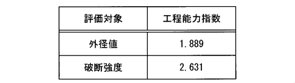
- FIG. 5 shows the process capability index of the outer diameter value and the breaking strength at the joint 122 of the joining conductor 120 manufactured using the conductor welding tube 10 made of alumina-based ceramics having a Mohs hardness of 8. . That is, the process capability index of the outer diameter value at the joint 122 is 1.889, the process capability index of the breaking strength is 2.631, and the process capability index of the selection criterion is 1.33 or more.
- the conducting wire welding tube 10 having a Mohs hardness of 8 or more by using the conducting wire welding tube 10 having a Mohs hardness of 8 or more, enlargement of the abutting portion of the conducting wire 20 at the time of welding can be effectively suppressed. Variations in the diameter value and the breaking strength with respect to each target value can be suppressed. From the above results, it was determined that a material having a Mohs hardness of 8 or more should be adopted as the material for the tube 10 for conducting wire welding.
Landscapes
- Engineering & Computer Science (AREA)
- Mechanical Engineering (AREA)
- Physics & Mathematics (AREA)
- Optics & Photonics (AREA)
- Manufacturing Of Electrical Connectors (AREA)
- Connections Effected By Soldering, Adhesion, Or Permanent Deformation (AREA)
Abstract
導線溶接用チューブは、2つの導線の端部同士の溶接において溶接部分を覆う部材である。この導線溶接用チューブは、モース硬度が8以上の材料により、2つの導線を両側から挿入可能な中空部を有する筒状に形成されている。
Description
導線の端部同士を溶接する技術に関する。
電線の製造過程において、導線を後工程に連続供給するため、連続しない導線の端部同士を接続することがある。導線の端部同士の接続には、アプセット溶接等の突き合わせ抵抗溶接が採用されることがある。突き合わせ抵抗溶接においては、各導線端部を突き合わせて通電させると共に突き合わせ方向に加圧することにより溶接する。この際、導線同士の接合部においては、加圧により導線の断面の肥大化(据込み(アプセット)ともいう)が生じる。
上記のようにように連続供給される導線は、電線の製造過程において、クロスヘッドダイ等における導線押し出し用のダイス(ポイント治具)を通じて押し出される(引き出される)。この場合、溶接により肥大化した接合部がダイスを通過する際に引っ掛かって、導線が断線する恐れがある。
上記問題に対して、溶接時に肥大化が生じる導線端部を、ステアタイト(MgOSiO2)等のセラミックチューブ内に挿入した状態で溶接を行い、肥大化を抑制する工法も考えられる。
しかしながら、ステアタイト製のチューブを用いても、接合部が大きく肥大化してしまうことがあり、肥大化を有効に抑制することが困難であった。
そこで、本発明は、接合部の肥大化を抑制することを目的とする。
第1の態様は、2つの導線の端部同士の溶接において溶接部分を覆う導線溶接用チューブであって、モース硬度が8以上の材料により、前記2つの導線を両側から挿入可能な中空部を有する筒状に形成されている。
第2の態様は、第1の態様に係る導線溶接用チューブであって、セラミックスにより形成されている。
第3の態様は、第2の態様に係る導線溶接用チューブであって、アルミナ系セラミックスにより形成されている。
第4の態様は、第2又は3の態様に係る導線溶接用チューブであって、気孔率が0%に設定されている。
第5の態様は、2つの導線の端部同士を溶接した接合導線の製造方法であって、(a)前記2つの導線の端部を、第1~第4のいずれか一態様に係る導線溶接用チューブの中空部内に挿入して突き合わせる工程と、(b)前記2つの導線の突き合わせ部分に電圧を印加する工程とを備える。
第1の態様に係る導線溶接用チューブによると、モース硬度が8以上の材料により、2つの導線を両側から挿入可能な中空部を有する筒状に形成されているため、その内部で導線の端部同士を溶接することにより、接合部の肥大化を抑制することができる。
第2の態様に係る導線溶接用チューブによると、セラミックスにより形成されているため、耐熱性に優れると共に、比較的破壊しやすく溶接後の除去作業性を向上させることができる。
第3の態様に係る導線溶接用チューブによると、アルミナ系セラミックスにより形成されているため、硬度、耐熱性、破壊性のバランスがよい。
第4の態様に係る導線溶接用チューブによると、気孔率が0%に設定されているため、より高い硬度を得ることができ、溶接における接合部の肥大化をより効果的に抑制することができる。
第5の態様に係る接合導線の製造方法によると、2つの導線の端部を導線溶接用チューブの中空部内に挿入して突き合わせ、2つの導線の突き合わせ部分に電圧を印加することにより溶接を行っている。これにより、導線における導線溶接用チューブの中空部内で溶融する部分の外周側への広がりを抑制して、接合部の肥大化を抑制して接合導線を製造することができる。
実施形態に係る導線溶接用チューブ10について説明する(図1参照)。この導線溶接用チューブ10は、導線20同士を突き合わせ抵抗溶接する際の接合部の肥大化を抑制するための部材である。
ここで、溶接対象となる導線20は、アルミニウム(又はアルミニウム合金)、銅(又は銅合金)等により形成されている単芯線又は複数の芯線を縒り合わせて圧縮した導線である。ここでは、導線20が、延在方向に直交する断面視において略円形に形成されている例で説明する。
<導線溶接用チューブ>
導線溶接用チューブ10は、溶接時に、溶接される2つの導線20の端部を覆う部材である。この導線溶接用チューブ10は、2つの導線20を両側から挿入可能な中空部12を有する筒状に形成されている(図1参照)。この中空部12は、導線20の外形に対応した形状であり、内側に略円柱状空間を有している。ここでは、中空部12は、導線20の外形より僅かに大きく形成されている。より具体的には、中空部12は、内部で2つの導線20が溶接されて形成される接合部122が、引き抜き又は押し出し用ダイスを断線等なく通過可能な大きさ(径)の断面形状に設定されている。すなわち、中空部12は、導線20を挿入可能で且つダイスを通過可能な最大の大きさ(径)と同じ又はそれより小さい大きさの内部形状に形成されている。また、ここでは、導線溶接用チューブ10は、全体として円筒状に形成されている。
導線溶接用チューブ10は、溶接時に、溶接される2つの導線20の端部を覆う部材である。この導線溶接用チューブ10は、2つの導線20を両側から挿入可能な中空部12を有する筒状に形成されている(図1参照)。この中空部12は、導線20の外形に対応した形状であり、内側に略円柱状空間を有している。ここでは、中空部12は、導線20の外形より僅かに大きく形成されている。より具体的には、中空部12は、内部で2つの導線20が溶接されて形成される接合部122が、引き抜き又は押し出し用ダイスを断線等なく通過可能な大きさ(径)の断面形状に設定されている。すなわち、中空部12は、導線20を挿入可能で且つダイスを通過可能な最大の大きさ(径)と同じ又はそれより小さい大きさの内部形状に形成されている。また、ここでは、導線溶接用チューブ10は、全体として円筒状に形成されている。
例えば、導線溶接用チューブ10は、軸方向寸法を6mm、外径を6mm(又は9mm)に設計すると共に、直径0.75mmの導線20に対して中空部12の内径を0.9±0.01mmに設計して形成することができる。
この導線溶接用チューブ10は、モース硬度が8以上のセラミックス材料により形成されている。ここでは、導線溶接用チューブ10の材料として、アルミナ(Al2O3)系セラミックスが採用されている。ここで、導線溶接用チューブ10の材料として採用されるアルミナ系セラミックスは、耐熱性及び硬度の向上のため、緻密化により気孔率が0%に設定されて形成されている。なお、気孔率0%とは、0%を目標値として形成する上で不可避的に生ずる誤差範囲も含むものとする。ここで、気孔率とは、容積中に占める気孔総容積の割合をいい、緻密化とは、セラミック粉体の成形体が焼成等の熱処理又は焼結によって密度を向上させ気孔が消滅する現象をいう。
もっとも、導線溶接用チューブ10は、上記材料により形成されるものに限られるものではない。すなわち、導線溶接用チューブは、モース硬度が8以上の材料で形成されていれば、アルミナ系セラミックス以外のセラミックス材料等、又は、気孔率が0%より大きい材料を採用してもよい。もっとも、気孔率が低い緻密なものが採用されることが好ましい。
また、導線溶接用チューブ10は、円筒状に限られるものではない。例えば、導線溶接用チューブは、略円柱状空間を有する中空部12を有すると共に、外形が中空部12の貫通方向に直交する断面視において多角形状に形成されていてもよい。
<接合導線の製造方法>
次に、上記導線溶接用チューブ10を用いた接合導線120の製造方法について説明する(図2~図4参照)。
次に、上記導線溶接用チューブ10を用いた接合導線120の製造方法について説明する(図2~図4参照)。
まず、溶接対象の2つの導線20の端部を、導線溶接用チューブ10の中空部12内に挿入して突き合わせる(図2参照)。より具体的には、各導線20を、それぞれ導線溶接用チューブ10の両側から中空部12内に挿入する。すなわち、各導線20は、端面同士が接触し、中心軸が略同軸上に位置する形態で突き合わされる。ここで、端部同士の突き合わせ部分は、接触する向きに加圧された状態となっている。
導線20を突き合わせた状態で、その突き合わせ部分に電圧を印加する(図3参照)。より具体的には、各導線20における導線溶接用チューブ10の両側から伸び出る部位間に電圧を印加する。これにより、導線20の突き合わせ部分は、導線20の端部同士の接触抵抗及び導線20の固有抵抗(主として導線20の端部同士の接触抵抗)により発熱して溶融する。
電圧を印加した状態で、2つの導線20を突き合わせ方向に相対近接移動させていき、該導線20の突き合わせ部分をさらに加圧する(図3参照)。この作業は、導線20の突き合わせ部分が導線溶接用チューブ10内に位置する状態で行う。そして、中空部12内に押し込まれる導線20により、導線20における溶融した部分(以下、溶融部分)が外周側に押し広げられ、中空部12の内周面に押し付けられる。すなわち、高い硬度を有する導線溶接用チューブ10の中空部12により溶融部分の逃げ道が規制され、形成される接合部122の形状が規制される。なお、図3では、導線20における溶融部分にハッチングを付している。
そして、電圧の印加が解除されて温度低下した溶融部分が凝固することにより、導線20同士の接合部122が形成される。すなわち、この接合部122は、導線溶接用チューブ10の中空部12の形状に沿った形状(略同じ断面形状)である。その後、導線溶接用チューブ10を接合部122の外周位置から除去する(図4参照)。より具体的には、導線溶接用チューブ10を破壊して除去する。以上の工程により、2つの導線20の端部同士を溶接した接合導線120が製造される。なお、図4では、導線溶接用チューブ10がない場合の肥大化した突き合わせ部分の形状を、2点鎖線で示している。
上記作業は、専用の機器によって行ってもよい。例えば、導線20を把持可能であると共に該導線20に電圧を印加可能に溶接電源に接続された一対の電極ダイ50を、相対近接離間移動可能に支持する構成を採用することができる(図3参照)。すなわち、2つの導線20を各電極ダイ50によりそれぞれ把持して、その各端部を導線溶接用チューブ10の中空部12内に挿入して突き合わせ、一対の電極ダイ50間に電圧を印加すると共に導線20を相対近接移動させて溶接する。
もっとも、導線20の溶接は、導線20同士の突き合わせ部分に電圧を印加しつつ、導線20を突き合わせ方向に近接移動させればよく、工程としては、導線20を近接移動させる向きに力を作用させてから突き合わせ部分に電圧を印加してもよいし、電圧の印加と導線20の近接移動を同時に行ってもよい。
また、ここでは、アプセット溶接を例に挙げて説明したが、接合部122の肥大化が生じ得るフラッシュ溶接等の突き合わせ抵抗溶接でも、導線溶接用チューブ10を適用することができる。
上記実施形態に係る導線溶接用チューブ10によると、モース硬度が8以上の材料により、2つの導線20を両側から挿入可能な中空部12を有する筒状に形成されているため、その内部で導線20の端部同士を溶接することにより、接合部122の肥大化を抑制することができる。
また、導線溶接用チューブ10がセラミックスにより形成されていることにより、耐熱性に優れると共に、比較的破壊し易く溶接後の除去作業性を向上させることができる。さらに、アルミナ系セラミックスが採用されているため、硬度、耐熱性、破壊性に優れている。
また、導線溶接用チューブ10が気孔率が0%に設計されていることにより、より高い硬度を得ることができ、溶接における接合部122の肥大化をより効果的に抑制することができる。
また、導線溶接用チューブ10を用いた接合導線120の製造方法によると、2つの導線20の端部を導線溶接用チューブ10の中空部12内に挿入して突き合わせ、2つの導線20の突き合わせ部分に電圧を印加することにより溶接を行っている。これにより、導線20における導線溶接用チューブ10の中空部12内で溶融する部分の外周側への広がりを抑制して、接合部122の肥大化を抑制して接合導線120を製造することができる。また、製造される接合導線120における接合部122の外径及び破断強度の個体ごとのばらつきを抑制することもできる。
<実施例>
次に、導線溶接用チューブ10の材料の選定について説明する。ここでは、導線20の接合部122における外径値及び破断強度の工程能力指数(Cpk値)を評価対象として、材料の選定を行った。
次に、導線溶接用チューブ10の材料の選定について説明する。ここでは、導線20の接合部122における外径値及び破断強度の工程能力指数(Cpk値)を評価対象として、材料の選定を行った。
本実験では、アルミ線(直径0.75mm)である導線20を溶接対象としている。そして、接合部122における外径の狙い値0.90mmに対する上限値を0.92mmとし、破断強度の狙い値120MPaに対する下限値を100MPaとしている。また、実験においては、上記のように導線溶接用チューブ10を用いて製造される接合導線120のデータ数(N)を30個とし、選定基準を工程能力指数1.33以上を満たすものとしている。
図5には、モース硬度が8であるアルミナ系セラミックスを材料とする導線溶接用チューブ10を用いて製造した接合導線120の接合部122における外径値及び破断強度の工程能力指数を示している。すなわち、この接合部122における外径値の工程能力指数は1.889、破断強度の工程能力指数は2.631であり、選定基準の工程能力指数1.33以上となっている。
すなわち、モース硬度8以上の導線溶接用チューブ10を用いることにより、溶接時の導線20の突き合わせ部分の肥大化を効果的に抑制することができ、製造される接合導線120の接合部122の外径値及び破断強度の各狙い値に対するばらつきを抑制することができる。以上の結果より、導線溶接用チューブ10の材料としてモース硬度8以上の材料を採用するとよいことを判断した。
以上のようにこの導線溶接用チューブ10及び接合導線の製造方法は詳細に説明されたが、上記した説明は、全ての局面において例示であって、この発明がそれに限定されるものではない。例示されていない無数の変形例が、この発明の範囲から外れることなく想定され得るものと解される。
10 導線溶接用チューブ
12 中空部
20 導線
50 電極ダイ
120 接合導線
122 接合部
12 中空部
20 導線
50 電極ダイ
120 接合導線
122 接合部
Claims (5)
- 2つの導線の端部同士の溶接において溶接部分を覆う導線溶接用チューブであって、
モース硬度が8以上の材料により、前記2つの導線を両側から挿入可能な中空部を有する筒状に形成されている、導線溶接用チューブ。 - 請求項1に記載の導線溶接用チューブであって、
セラミックスにより形成されている、導線溶接用チューブ。 - 請求項2に記載の導線溶接用チューブであって、
アルミナ系セラミックスにより形成されている、導線溶接用チューブ。 - 請求項2に記載の導線溶接用チューブであって、
気孔率が0%に設定されている、導線溶接用チューブ。 - 2つの導線の端部同士を溶接した接合導線の製造方法であって、
(a)前記2つの導線の端部を、請求項1に記載の導線溶接用チューブの中空部内に挿入して突き合わせる工程と、
(b)前記2つの導線の突き合わせ部分に電圧を印加する工程と、
を備える、接合導線の製造方法。
Applications Claiming Priority (2)
| Application Number | Priority Date | Filing Date | Title |
|---|---|---|---|
| JP2011092550A JP2012223786A (ja) | 2011-04-19 | 2011-04-19 | 導線溶接用チューブ及び接合導線の製造方法 |
| JP2011-092550 | 2011-04-19 |
Publications (1)
| Publication Number | Publication Date |
|---|---|
| WO2012144106A1 true WO2012144106A1 (ja) | 2012-10-26 |
Family
ID=47041243
Family Applications (1)
| Application Number | Title | Priority Date | Filing Date |
|---|---|---|---|
| PCT/JP2011/078384 Ceased WO2012144106A1 (ja) | 2011-04-19 | 2011-12-08 | 導線溶接用チューブ及び接合導線の製造方法 |
Country Status (2)
| Country | Link |
|---|---|
| JP (1) | JP2012223786A (ja) |
| WO (1) | WO2012144106A1 (ja) |
Families Citing this family (2)
| Publication number | Priority date | Publication date | Assignee | Title |
|---|---|---|---|---|
| JP6472424B2 (ja) | 2016-11-10 | 2019-02-20 | 矢崎総業株式会社 | 電線の接合方法 |
| DE102017213899A1 (de) * | 2017-08-09 | 2019-02-14 | Strunk Connect automated solutions GmbH & Co. KG | Verfahren zum Widerstands-Stumpfschweißen |
Citations (4)
| Publication number | Priority date | Publication date | Assignee | Title |
|---|---|---|---|---|
| JPH01210178A (ja) * | 1988-02-15 | 1989-08-23 | Sumikura Kozai Kk | 鉄筋または線材の電気圧接方法 |
| JPH01218774A (ja) * | 1988-02-26 | 1989-08-31 | Tokai Rika Co Ltd | バット溶接法及びそれに用いる押さえ型 |
| JPH03291174A (ja) * | 1990-04-05 | 1991-12-20 | Matsushita Electric Ind Co Ltd | 線材の接続方法 |
| JPH08118033A (ja) * | 1994-10-17 | 1996-05-14 | Mitsubishi Heavy Ind Ltd | より線電線の接続方法 |
-
2011
- 2011-04-19 JP JP2011092550A patent/JP2012223786A/ja not_active Withdrawn
- 2011-12-08 WO PCT/JP2011/078384 patent/WO2012144106A1/ja not_active Ceased
Patent Citations (4)
| Publication number | Priority date | Publication date | Assignee | Title |
|---|---|---|---|---|
| JPH01210178A (ja) * | 1988-02-15 | 1989-08-23 | Sumikura Kozai Kk | 鉄筋または線材の電気圧接方法 |
| JPH01218774A (ja) * | 1988-02-26 | 1989-08-31 | Tokai Rika Co Ltd | バット溶接法及びそれに用いる押さえ型 |
| JPH03291174A (ja) * | 1990-04-05 | 1991-12-20 | Matsushita Electric Ind Co Ltd | 線材の接続方法 |
| JPH08118033A (ja) * | 1994-10-17 | 1996-05-14 | Mitsubishi Heavy Ind Ltd | より線電線の接続方法 |
Also Published As
| Publication number | Publication date |
|---|---|
| JP2012223786A (ja) | 2012-11-15 |
Similar Documents
| Publication | Publication Date | Title |
|---|---|---|
| CN101472701A (zh) | 焊接/接合前高压/高速焊接或接合第一和第二金属工件的方法、及由该方法制成的制造品 | |
| EP3086897B1 (en) | Welding assembly and method | |
| EP3261181B1 (en) | Conductor transition joint device and method | |
| JP2023013803A (ja) | 摩擦攪拌接合及び抵抗溶接のための接合装置及び接合方法 | |
| JP5220449B2 (ja) | 金属部材の接合方法及びその装置 | |
| WO2012144106A1 (ja) | 導線溶接用チューブ及び接合導線の製造方法 | |
| US10821554B2 (en) | Method of manufacturing conductive member and conductive member | |
| JP4877110B2 (ja) | コンデンサ用リード端子の製造方法 | |
| JP5491093B2 (ja) | 抵抗溶接装置 | |
| CN109494542B (zh) | 用于将电的铝导线与铝管道连接的方法 | |
| US20040188389A1 (en) | Method for resistance welding a tube to a member | |
| WO2012089038A1 (zh) | V形面铜铝焊接加工工艺及电力电缆用焊接接头 | |
| KR100895877B1 (ko) | 냉간 용접기 및 이를 이용한 선재 접합 방법 | |
| JP5566413B2 (ja) | 冷間圧接用ダイス | |
| US12330234B2 (en) | Method and apparatus for processing an electrical conductor | |
| CN107538094B (zh) | 一种多股导线与微细丝的精密电阻钎焊方法 | |
| KR101954066B1 (ko) | 동관단자 제조방법 | |
| JP7323740B2 (ja) | 電解コンデンサ用リード端子及びその製造方法 | |
| US9649717B2 (en) | Welding assembly and method | |
| JP6569345B2 (ja) | 抵抗溶接用の電極および端子付き電線 | |
| US20200001390A1 (en) | Joining apparatus and method of joining | |
| JP6612098B2 (ja) | 金属接合線の製造方法及びダイス | |
| JP2021186842A (ja) | 接合物品の製造方法及び製造装置 | |
| US20200003086A1 (en) | Joining apparatus and method of joining | |
| KR20170142062A (ko) | 마찰 교반 용접에 의한 핀홀 리페어 방법 및 시스템 |
Legal Events
| Date | Code | Title | Description |
|---|---|---|---|
| 121 | Ep: the epo has been informed by wipo that ep was designated in this application |
Ref document number: 11863882 Country of ref document: EP Kind code of ref document: A1 |
|
| NENP | Non-entry into the national phase |
Ref country code: DE |
|
| 122 | Ep: pct application non-entry in european phase |
Ref document number: 11863882 Country of ref document: EP Kind code of ref document: A1 |