WO2012144027A1 - Vehicle periphery alert device - Google Patents
Vehicle periphery alert device Download PDFInfo
- Publication number
- WO2012144027A1 WO2012144027A1 PCT/JP2011/059715 JP2011059715W WO2012144027A1 WO 2012144027 A1 WO2012144027 A1 WO 2012144027A1 JP 2011059715 W JP2011059715 W JP 2011059715W WO 2012144027 A1 WO2012144027 A1 WO 2012144027A1
- Authority
- WO
- WIPO (PCT)
- Prior art keywords
- vehicle
- warning
- traveling direction
- warning device
- peripheral
- Prior art date
Links
Images


Classifications
-
- B—PERFORMING OPERATIONS; TRANSPORTING
- B60—VEHICLES IN GENERAL
- B60W—CONJOINT CONTROL OF VEHICLE SUB-UNITS OF DIFFERENT TYPE OR DIFFERENT FUNCTION; CONTROL SYSTEMS SPECIALLY ADAPTED FOR HYBRID VEHICLES; ROAD VEHICLE DRIVE CONTROL SYSTEMS FOR PURPOSES NOT RELATED TO THE CONTROL OF A PARTICULAR SUB-UNIT
- B60W30/00—Purposes of road vehicle drive control systems not related to the control of a particular sub-unit, e.g. of systems using conjoint control of vehicle sub-units, or advanced driver assistance systems for ensuring comfort, stability and safety or drive control systems for propelling or retarding the vehicle
- B60W30/08—Active safety systems predicting or avoiding probable or impending collision or attempting to minimise its consequences
-
- G—PHYSICS
- G08—SIGNALLING
- G08G—TRAFFIC CONTROL SYSTEMS
- G08G1/00—Traffic control systems for road vehicles
- G08G1/16—Anti-collision systems
- G08G1/166—Anti-collision systems for active traffic, e.g. moving vehicles, pedestrians, bikes
-
- B—PERFORMING OPERATIONS; TRANSPORTING
- B60—VEHICLES IN GENERAL
- B60Q—ARRANGEMENT OF SIGNALLING OR LIGHTING DEVICES, THE MOUNTING OR SUPPORTING THEREOF OR CIRCUITS THEREFOR, FOR VEHICLES IN GENERAL
- B60Q1/00—Arrangement of optical signalling or lighting devices, the mounting or supporting thereof or circuits therefor
- B60Q1/26—Arrangement of optical signalling or lighting devices, the mounting or supporting thereof or circuits therefor the devices being primarily intended to indicate the vehicle, or parts thereof, or to give signals, to other traffic
- B60Q1/50—Arrangement of optical signalling or lighting devices, the mounting or supporting thereof or circuits therefor the devices being primarily intended to indicate the vehicle, or parts thereof, or to give signals, to other traffic for indicating other intentions or conditions, e.g. request for waiting or overtaking
- B60Q1/503—Arrangement of optical signalling or lighting devices, the mounting or supporting thereof or circuits therefor the devices being primarily intended to indicate the vehicle, or parts thereof, or to give signals, to other traffic for indicating other intentions or conditions, e.g. request for waiting or overtaking using luminous text or symbol displays in or on the vehicle, e.g. static text
-
- B—PERFORMING OPERATIONS; TRANSPORTING
- B60—VEHICLES IN GENERAL
- B60R—VEHICLES, VEHICLE FITTINGS, OR VEHICLE PARTS, NOT OTHERWISE PROVIDED FOR
- B60R21/00—Arrangements or fittings on vehicles for protecting or preventing injuries to occupants or pedestrians in case of accidents or other traffic risks
- B60R21/01—Electrical circuits for triggering passive safety arrangements, e.g. airbags, safety belt tighteners, in case of vehicle accidents or impending vehicle accidents
- B60R21/013—Electrical circuits for triggering passive safety arrangements, e.g. airbags, safety belt tighteners, in case of vehicle accidents or impending vehicle accidents including means for detecting collisions, impending collisions or roll-over
- B60R21/0134—Electrical circuits for triggering passive safety arrangements, e.g. airbags, safety belt tighteners, in case of vehicle accidents or impending vehicle accidents including means for detecting collisions, impending collisions or roll-over responsive to imminent contact with an obstacle, e.g. using radar systems
-
- B—PERFORMING OPERATIONS; TRANSPORTING
- B60—VEHICLES IN GENERAL
- B60W—CONJOINT CONTROL OF VEHICLE SUB-UNITS OF DIFFERENT TYPE OR DIFFERENT FUNCTION; CONTROL SYSTEMS SPECIALLY ADAPTED FOR HYBRID VEHICLES; ROAD VEHICLE DRIVE CONTROL SYSTEMS FOR PURPOSES NOT RELATED TO THE CONTROL OF A PARTICULAR SUB-UNIT
- B60W30/00—Purposes of road vehicle drive control systems not related to the control of a particular sub-unit, e.g. of systems using conjoint control of vehicle sub-units, or advanced driver assistance systems for ensuring comfort, stability and safety or drive control systems for propelling or retarding the vehicle
- B60W30/06—Automatic manoeuvring for parking
-
- G—PHYSICS
- G08—SIGNALLING
- G08G—TRAFFIC CONTROL SYSTEMS
- G08G1/00—Traffic control systems for road vehicles
- G08G1/16—Anti-collision systems
- G08G1/168—Driving aids for parking, e.g. acoustic or visual feedback on parking space
-
- B—PERFORMING OPERATIONS; TRANSPORTING
- B60—VEHICLES IN GENERAL
- B60Q—ARRANGEMENT OF SIGNALLING OR LIGHTING DEVICES, THE MOUNTING OR SUPPORTING THEREOF OR CIRCUITS THEREFOR, FOR VEHICLES IN GENERAL
- B60Q1/00—Arrangement of optical signalling or lighting devices, the mounting or supporting thereof or circuits therefor
- B60Q1/26—Arrangement of optical signalling or lighting devices, the mounting or supporting thereof or circuits therefor the devices being primarily intended to indicate the vehicle, or parts thereof, or to give signals, to other traffic
- B60Q1/50—Arrangement of optical signalling or lighting devices, the mounting or supporting thereof or circuits therefor the devices being primarily intended to indicate the vehicle, or parts thereof, or to give signals, to other traffic for indicating other intentions or conditions, e.g. request for waiting or overtaking
- B60Q1/507—Arrangement of optical signalling or lighting devices, the mounting or supporting thereof or circuits therefor the devices being primarily intended to indicate the vehicle, or parts thereof, or to give signals, to other traffic for indicating other intentions or conditions, e.g. request for waiting or overtaking specific to autonomous vehicles
Definitions
- the present invention relates to a vehicle peripheral warning device that is mounted on a vehicle and that operates when the vehicle moves backward from a parked state.
- the vehicle when the vehicle is parked, it is parked at a right angle with respect to the original traveling zone (including a portion other than a normal traveling road and a parking frame line in a parking lot where a plurality of vehicles can be parked). Not necessarily.
- the possibility of parking at an angle close to or parallel to the traveling zone is also assumed. Therefore, if the above-mentioned warning area is set uniformly, the warning area may be displaced from the area that should be warned depending on the angle with respect to the traveling zone.
- a crossing traffic warning device that takes into account such a problem is known (see, for example, Patent Document 1).
- the parking angle which is the angle of the parked vehicle with respect to the traveling zone, is calculated by sampling the yaw rate and the steering angle until the parking state is reached, and stored in a nonvolatile memory or the like.
- the angle range of the warning area is set based on the parking angle (Figs. 2, 4, and 5).
- the sampling start time of the yaw rate or steering steering angle is not always accurate, and an error may occur depending on the sampling period, so that the parking angle is not always calculated accurately. For this reason, the angle range of the warning area may not be set appropriately.
- the present invention is for solving such a problem, and provides a vehicle periphery warning device capable of appropriately performing warning for other vehicles behind the vehicle while suppressing an increase in cost and weight. Is the main purpose.
- the first aspect of the present invention provides: A vehicle peripheral warning device that is mounted on a vehicle and that operates when the vehicle starts moving backward from a parking state, Detecting means for detecting the position and traveling direction of another vehicle present on the rear side of the vehicle; A warning action activating means for performing a predetermined warning action in the vehicle; A virtual warning area is set on the rear side of the vehicle according to an angle formed by the traveling direction of the vehicle and the traveling direction of the other vehicle, and the position of the other vehicle is in the set warning area. Control means for activating the warning action activating means when a condition including A vehicle peripheral warning device.
- a virtual warning area is set on the rear side of the vehicle according to the angle formed by the traveling direction of the vehicle and the traveling direction of the other vehicle, and the position of the other vehicle is set. Since the warning action activating means is activated when the condition including the presence in the warning area is satisfied, warning for other vehicles behind the vehicle can be appropriately performed while suppressing an increase in cost and weight.
- the second aspect of the present invention provides: A vehicle peripheral warning device that is mounted on a vehicle and that operates when the vehicle starts moving backward from a parking state, Detecting means for detecting the position and traveling direction of another vehicle present on the rear side of the vehicle; A warning action activating means for performing a predetermined warning action in the vehicle; A control means for setting a virtual warning line extending rearward from a side end of the vehicle and operating the warning action activating means when it is determined that the other vehicle crosses the warning line within a predetermined time; , A vehicle peripheral warning device.
- a virtual warning line extending backward from the side end of the vehicle is set, and a warning operation is performed when it is determined that another vehicle crosses the warning line within a predetermined time. Since the activating means is activated, it is possible to appropriately warn other vehicles behind the vehicle while suppressing an increase in cost and weight.
- a vehicle surrounding warning device that can appropriately warn other vehicles behind the vehicle while suppressing an increase in cost and weight.
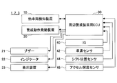
- FIG. 1 is a system configuration example of a vehicle surrounding warning device 1 according to a first embodiment of the present invention. It is the figure which illustrated the detectable range of other vehicles detection device 10 which is a millimeter wave radar device. It is the figure which illustrated the detectable range of other vehicles detection device 10 which is a millimeter wave radar device.
- It is the figure which illustrated correspondence of distance D and angle theta It is the figure which illustrated correspondence of distance D and angle theta.
- warning area WA set up It is the figure which illustrated warning area WA set up in various situations. It is the figure which illustrated warning area WA set up in various situations. It is the figure which illustrated warning area WA set up in various situations. It is a figure which shows a mode that the alert area WA is reset according to the own vehicle 100 moving. It is a flowchart which shows the flow of the process performed by ECU30 for periphery warning devices. It is an example of the alert area WA set by the peripheral alert device ECU 30 according to the second embodiment. It is an example of a warning line WL set behind the host vehicle 100. It is the figure which illustrated correspondence of warning line WL and angle theta. It is the figure which illustrated correspondence of warning line WL and angle theta. It is the figure which illustrated the warning line WL set up in various situations. 2 is a configuration example of an electronically controlled brake device 50 that can be employed as a warning action activation device 20.
- FIG. 1 is a system configuration example of a vehicle periphery warning device 1 according to a first embodiment of the present invention.
- the vehicle surrounding warning device 1 includes, as main components, an other vehicle detection device 10, a warning action activation device 20, and a peripheral warning device ECU (Electronic Control Unit) 30.
- ECU Electronic Control Unit
- a vehicle equipped with the vehicle periphery warning device 1 is referred to as “own vehicle”, and a vehicle that is a warning target is referred to as “other vehicle”.
- the other vehicle detection device 10 is, for example, a millimeter wave radar device attached inside the rear bumper of the host vehicle.
- the other vehicle detection device 10 transmits a bumper formed of resin or the like to radiate electromagnetic waves to the rear of the vehicle, detects a reflected wave, and detects the position, traveling direction, and speed of the obstacle behind the vehicle.
- 2 and 3 are diagrams illustrating the detectable range Rd of the other vehicle detection device 10 that is a millimeter wave radar device.
- the other vehicle detection device 10 may include one millimeter wave radar device 10 * or may include a plurality of millimeter wave radar devices 10 *, 10 **. Good.
- Fw forward direction of the host vehicle
- the millimeter wave radar device first generates a modulation signal obtained by modulating a triangular wave, outputs a transmission signal modulated so that the frequency increases or decreases according to the gradient of the triangular wave, and converts a part of the transmission signal to the reception signal. Generate a mixed beat signal. Then, the millimeter wave radar device generates frequency spectrum data by performing FFT (Fast Fourier transform) processing or the like on the beat signals in the up and down sections of the modulation cycle, and the received wave intensity peaks from the frequency spectrum data. Search for the peak frequency to be formed.
- FFT Fast Fourier transform
- the millimeter wave radar device calculates the distance R to the obstacle and the relative velocity V according to the following equations (1) to (4). obtain.
- fm is the repetition frequency of the triangular wave that is the source of the transmission signal
- ⁇ F is the frequency shift width
- f 0 is the center frequency of the modulated wave.
- fr (fb1 + fb2) / 2 (1)
- fd (fb1-fb2) / 2 (2)
- R (C / (4 ⁇ ⁇ F ⁇ fm)) ⁇ fr ...
- V (C / (2 ⁇ f 0 )) ⁇ fd ... (4).
- the direction of the obstacle can be calculated by DBF.
- DBF is a technique for forming the directivity of an antenna by performing phase and amplitude conversion based on such a principle and synthesizing the received waves of each antenna element. Thereby, the millimeter wave radar device can obtain the direction ⁇ of the obstacle.
- the millimeter wave radar device uses the position of the obstacle with reference to the predetermined position of the own vehicle and the center axis (that is, the traveling direction) of the own vehicle as a reference.
- the moving direction of the obstacle, the moving speed of the obstacle, etc. can be calculated.
- a difference in relative position in a minute period may be obtained, or vector calculation may be performed using the relative speed V, the azimuth angle ⁇ , and the speed of the host vehicle as parameters.
- the millimeter wave radar device screens (screens) obstacles whose positions, moving directions, speeds, etc. are calculated based on the received wave intensity, estimated size, speed, etc. Extract vehicles from things.
- the millimeter wave radar device can obtain the position of the other vehicle behind the host vehicle, the traveling direction based on the center axis of the host vehicle, the speed, and the like.
- the present embodiment will be described on the premise of such a technique.
- a laser radar device As a means for acquiring information such as the position of other vehicles, a laser radar device, a stereo camera device, or the like can be employed in addition to the millimeter wave radar.
- the alert action issuing device 20 is a sounding device such as a speaker, for example, and is controlled to output a warning sound based on the presence of another vehicle, as will be described later.
- a buzzer 21, an indicator 22, a display device 23, etc. may be provided as means for invoking a warning action.
- the indicator 22 is an issuing means that is attached to an inner mirror, an outer mirror, a combination meter, etc., and lights up or blinks when a warning action is activated.
- the display device 23 is a display device that is shared with, for example, a navigation device, and performs lighting and flashing of an icon when a warning operation is activated. These display devices may be capable of indicating either the left or right direction with an arrow or the like so that the driver can recognize the arrival direction of the other vehicle when the other vehicle is detected.
- the peripheral warning device ECU 30 is, for example, a computer unit in which a ROM, a RAM, and the like are connected to each other via a bus with a CPU at the center. ) Etc., I / O port, timer, counter and the like.
- the peripheral warning device ECU 30 includes output signals from switches and sensors such as an ignition switch 40, a vehicle speed sensor 42, a shift position sensor 44, and an accelerator opening sensor 46, or other ECUs that perform vehicle control using these signals.
- the status signal etc. output from is input.
- the surrounding warning device ECU 30 operates the other vehicle detection device 10 when the host vehicle starts to move backward from the parked state, and the position of the other vehicle detected by the other vehicle detection device 10 extends to the rear side of the vehicle.
- the warning action activation 20 is activated to output a warning sound.
- other vehicles to be warned may be limited to other vehicles that are “approaching”, that is, whose relative distance is being shortened.
- the conditions for operating the warning action activation 20 may include other conditions such as a condition that the speed of the host vehicle or another vehicle is equal to or higher than a predetermined speed.
- the determination as to whether or not the vehicle is in the “parking state” includes, for example, (1) an ACC off signal is input from the ignition switch 40, and (2) the vehicle speed signal input from the vehicle speed sensor 42 is zero for a predetermined time or more. And a signal input from the shift position sensor 44 can be performed by setting conditions such as “P” (parking).
- FIG. 4 is an example of a warning area WA that is set by the peripheral warning device ECU 30 when the host vehicle 100 moves forward and parks at a right angle to the road and then starts moving backward.
- the warning area WA has, for example, a constant width X in the vehicle width direction around the vehicle central axis 100A of the host vehicle 100, and from the rear end portion 100B of the host vehicle 100 to the rear side.
- the farthest end WAF is set as a rectangular area that reaches a predetermined distance D along the vehicle center axis A direction of the vehicle.
- the warning area may include an area WA + extending forward from the rear end portion 100B of the host vehicle 100 as shown in the drawing (hereinafter, illustration and description thereof are omitted).
- the alert area WA may be set for each other target vehicle. Therefore, when a plurality of other vehicles 200 and 201 are traveling behind the host vehicle 100, the warning action triggering device 20 may be used even if the other vehicle is traveling within the warning area set for the other vehicle 200. There may be scenes that do not activate.
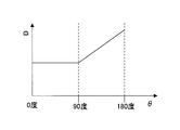
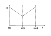
- the peripheral warning device ECU 30 determines the distance D to the farthest end WAF in the warning area WA according to the angle ⁇ between the traveling direction of the host vehicle and the traveling direction of the other vehicle.
- 5 and 6 are diagrams illustrating the correspondence between the distance D and the angle ⁇ .
- the traveling direction 100C of the host vehicle 100 and the traveling directions 200C and 201C of the other vehicles 200 and 201 are represented by arrows.
- the distance D is constant when the angle ⁇ between the traveling direction of the host vehicle and the traveling direction of the other vehicle is between 0 degrees and 90 degrees, and between 90 degrees and 180 degrees. Then, it may be set so that it becomes shorter as it approaches 90 degrees and becomes longer as it approaches 180 degrees.
- the distance D becomes shorter as the angle ⁇ between the traveling direction of the host vehicle and the traveling direction of the other vehicle is closer to 90 degrees, and becomes longer as it is farther from 90 degrees. It may be set as follows.
- the distance D changes linearly according to the change in the angle ⁇ , but it may change in a curved line or a step.
- the distance D is the shortest.
- FIGS. 7 to 10 are diagrams illustrating the warning area WA set in various situations in the case of following (1) above.
- the alert area WA * for the other vehicle 200 has the shortest distance D. It will be a thing. Further, since the angle ⁇ ** formed by the traveling direction 100C of the host vehicle 100 and the traveling direction 201D of the other vehicle 201 is 90 degrees, the warning area WA ** for the other vehicle 200 is also the shortest distance D. . As a result, the alert areas WA * and WA ** match. In the example of FIG. 7, the warning action activation device 20 is activated when the other vehicle 200 enters the warning area WA *, but the other vehicle 201 is farther from the farthest end portion WAF ** of the warning area WA **. Therefore, even if the other vehicle 201 travels as it is, the warning action activation device 20 does not activate.
- the angle ⁇ formed by the traveling direction 100C of the host vehicle 100 and the traveling direction 200C of the other vehicle 200 is, for example, 135 degrees. Therefore, the alert area WA * for the other vehicle 200 is the example shown in FIG. The distance D is longer than that of.
- the alert area WA * for the other vehicle 200 is the example shown in FIG.
- the distance D is further longer than that of.
- the warning area WA is far from the host vehicle 100 in a scene where the host vehicle 100 needs to be warned that the other vehicle is approaching from the opposite direction while the host vehicle 100 starts moving backward. Extended to the side. As a result, it is possible to appropriately warn other vehicles behind the vehicle.
- the alert area WA * for the other vehicle 200 has the shortest distance D. It will be a thing.
- FIG. 11 is a diagram illustrating a warning area WA set in the same situation as FIG. 10 in the case of following (2).
- the warning area WA * for the other vehicle 200 is compared with the example shown in FIG.
- the distance D becomes long.
- the angle between the host vehicle and the other vehicle is not limited to change according to the angle with respect to the road when the host vehicle is parked, but changes dynamically as the host vehicle moves from the parking position to the road. To do. Therefore, once the warning area WA is set at the time of departure, the warning area WA may not be held as it is, but may be reset as the host vehicle moves (for example, every predetermined travel distance).
- FIG. 12 is a diagram illustrating a state in which the alert area WA is reset as the host vehicle 100 moves. As shown in the figure, as the own vehicle 100 moves toward the road, the angle formed by the traveling direction 100C of the own vehicle 100 and the traveling direction 200C of the other vehicle 200 also changes. Is set.
- FIG. 13 is a flowchart showing a flow of processing executed by the peripheral warning device ECU 30.
- the peripheral warning device ECU 30 determines whether or not the vehicle is in a scene of starting backward from the parking state (S300). The specific contents of this determination are as described above.
- the surrounding warning device ECU 30 determines that the vehicle is in a situation of starting backward from the parking state, the other vehicle detection device 10 is operated (S302), and the position and traveling direction of the other vehicle are acquired (S304).
- the peripheral warning device ECU 30 sets a warning area based on the position of the other vehicle and the traveling direction (S306).
- the peripheral warning device ECU 30 determines whether another vehicle is traveling in the warning area (S308). When the other vehicle is traveling in the warning area, the peripheral warning device ECU 30 activates the warning action issuing device 20 (S310).
- the peripheral warning device ECU 30 repeatedly executes the processing of S304 to S310 until the shift position becomes other than “R” (S312). Note that the processing of S304 to S306 may be performed less frequently than the processing of S308 to S310.
- the distance D to the farthest end WAF in the warning area WA depends on the angle ⁇ between the traveling direction of the host vehicle and the traveling direction of the other vehicle. Therefore, it is possible to appropriately warn other vehicles behind the vehicle. Moreover, since it is not necessary to calculate the parking angle in advance and store it in the nonvolatile memory at the time of parking, it is possible to appropriately warn other vehicles behind the vehicle while suppressing an increase in cost and weight.
- the peripheral warning device ECU 30 does not extend or contract the warning area WA as in the first embodiment, but the warning area WA so that the longitudinal direction of the warning area WA follows the traveling direction of the other vehicle. Rotate.
- FIG. 14 is an example of a warning area WA set by the peripheral warning device ECU 30 according to the second embodiment.
- the peripheral warning device ECU 30 according to the second embodiment rotates the warning area WA so that the longitudinal direction WAL of the warning area WA is along the traveling direction 200C of the other vehicle 200.
- the distance D to the farthest end WAF of the alert area WA is extended.
- the warning area WA is extended to the side far from the host vehicle 100 in a scene where warning is required. As a result, it is possible to appropriately warn other vehicles behind the vehicle.
- the warning area WA is rotated along the traveling direction 200C of the other vehicle 200, so that it is possible to appropriately warn the other vehicle behind the vehicle. . Moreover, since it is not necessary to calculate the parking angle in advance and store it in the nonvolatile memory at the time of parking, it is possible to appropriately warn other vehicles behind the vehicle while suppressing an increase in cost and weight.
- the peripheral warning device ECU 30 sets a virtual warning line WL instead of the warning area WA, and starts a warning operation when it is determined that another vehicle crosses the warning line WL within a predetermined time.
- the means 20 is activated.
- FIG. 15 is an example of a warning line WL set behind the host vehicle 100.
- the warning line WL is a line extending backward from the side end portion of the host vehicle 100.
- the warning line may include a line WL + extending forward from the rearmost end of the side end of the host vehicle 100 as illustrated.
- the vehicle surrounding warning device 3 of the present embodiment may perform a warning operation using the warning area WA as in the first and second embodiments. Absent.
- the lower part of FIG. 15 schematically shows such a state.
- Whether or not the other vehicle 200 crosses the warning line WL can be determined based on the position of the other vehicle 200 and the traveling direction 200C. Whether or not to cross within a predetermined time is calculated by calculating the distance between the other vehicle 200 and the warning line WL from the position of the other vehicle 200 and the traveling direction 200C, and dividing the calculated distance by the speed of the other vehicle 200. Can be calculated.
- peripheral warning device ECU 30 of the third embodiment may extend or reduce the warning line according to the angle formed by the traveling direction of the host vehicle and the traveling direction of the other vehicle.
- the peripheral warning device ECU 30 (1) as shown in FIG. 16, the angle ⁇ between the traveling direction of the host vehicle and the traveling direction of the other vehicle is set to 0 to 90 degrees. It may be set to be constant, and between 90 degrees and 180 degrees, the distance may be shorter as it is closer to 90 degrees and longer as it is closer to 180 degrees.
- the peripheral warning device ECU 30 shortens the length of the warning line WL as the angle ⁇ between the traveling direction of the host vehicle and the traveling direction of the other vehicle approaches 90 degrees. It may be set so as to become longer as it is farther from 90 degrees.
- FIG. 18 is a diagram illustrating warning lines WL set in various situations in the case of following (1) above.
- the warning line WL is changed to be longer in a scene that requires the most warning that the own vehicle 100 starts moving backward and another vehicle is approaching from the opposite direction. As a result, it is possible to appropriately warn other vehicles behind the vehicle. Also in this case, the warning line WL may be reset as the vehicle 100 moves as in the first embodiment.
- the warning operation activating means 20 is activated when it is determined that the other vehicle crosses the warning line WL within a predetermined time. Be vigilant. Moreover, since it is not necessary to calculate the parking angle in advance and store it in the non-volatile memory at the time of parking, warning can be performed while suppressing an increase in cost and weight.
- the vehicle periphery warning device 3 of the present embodiment when the warning line is expanded or contracted according to the angle formed by the traveling direction of the own vehicle and the traveling direction of the other vehicle, the vehicle is warned against the other vehicle behind the vehicle. It can be done more appropriately.
- the warning action activation device 20 may perform automatic braking control instead of (or in addition to) a warning sound generated by a sound generation device such as a speaker or a buzzer.
- the warning action issuing device 20 includes an electronically controlled brake device that can output a braking force independently of the position of the brake pedal.
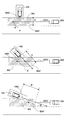
- FIG. 19 shows an example of the configuration of an electronically controlled brake device 50 that can be employed as the warning action activating device 20.
- the electronically controlled brake device 50 includes a brake ECU 50A, a master cylinder 51 to which a brake operation performed on a brake pedal is transmitted, a reservoir tank 52 that stores brake fluid, a stroke simulator 53, and a braking force that is output to each wheel.
- the brake actuator 54 includes a pump 55, a motor 56 that drives the pump 55, an accumulator 57 in which the internal hydraulic pressure is maintained at a high pressure by the hydraulic pressure fed from the pump 55, and a switching valve that can shut off the hydraulic pressure from the master cylinder 51.
- the switching valve 58 is normally closed, and the master cylinder 51 and the wheel control valves 59A to 59D are disconnected.
- the accumulator pressure inside the accumulator 57 is monitored by the brake ECU 50A.
- the motor 56 is driven so as to increase the accumulator pressure.
- the brake pedal 60 is depressed by the driver in this state, the master cylinder pressure generated in the hydraulic chamber inside the master cylinder 51 is input to the brake ECU 50A by communication.
- the brake ECU 50A controls the wheel control valves 59A to 59D so as to output a braking force corresponding to the master cylinder pressure.
- the electronically controlled brake device 50 can output a desired braking force by controlling the wheel control valves 59A to 59D regardless of the depression amount of the brake pedal 60.
- the electronically controlled brake device 50 is not limited to the electronically controlled brake device that operates by the hydraulic pressure described above, and an electronically controlled brake device that operates by an electric actuator may be used.
- warning area WA is set as a rectangular area, it may be an area having another shape such as a circle or an ellipse.
- the present invention can be used in the automobile industry, the automobile parts manufacturing industry, the computer software industry for automobiles, and the like.
Abstract
Description
車両に搭載され、該車両が駐車状態から後退発進する際に作動する車両用周辺警戒装置であって、
前記車両の後方側に存在する他車両の位置及び進行方向を検知する検知手段と、
前記車両において所定の警戒動作を行う警戒動作発動手段と、
前記車両の進行方向と前記他車両の進行方向とのなす角度に応じて前記車両の後方側に仮想的な警戒領域を設定し、前記他車両の位置が前記設定した警戒領域に在ることを含む条件を満たすときに前記警戒動作発動手段を作動させる制御手段と、
を備える車両用周辺警戒装置である。 In order to achieve the above object, the first aspect of the present invention provides:
A vehicle peripheral warning device that is mounted on a vehicle and that operates when the vehicle starts moving backward from a parking state,
Detecting means for detecting the position and traveling direction of another vehicle present on the rear side of the vehicle;
A warning action activating means for performing a predetermined warning action in the vehicle;
A virtual warning area is set on the rear side of the vehicle according to an angle formed by the traveling direction of the vehicle and the traveling direction of the other vehicle, and the position of the other vehicle is in the set warning area. Control means for activating the warning action activating means when a condition including
A vehicle peripheral warning device.
車両に搭載され、該車両が駐車状態から後退発進する際に作動する車両用周辺警戒装置であって、
前記車両の後方側に存在する他車両の位置及び進行方向を検知する検知手段と、
前記車両において所定の警戒動作を行う警戒動作発動手段と、
前記車両の側端部から後方に延出する仮想的な警戒線を設定し、前記他車両が所定時間以内に前記警戒線に交差すると判定したときに前記警戒動作発動手段を作動させる制御手段と、
を備える車両用周辺警戒装置である。 In order to achieve the above object, the second aspect of the present invention provides:
A vehicle peripheral warning device that is mounted on a vehicle and that operates when the vehicle starts moving backward from a parking state,
Detecting means for detecting the position and traveling direction of another vehicle present on the rear side of the vehicle;
A warning action activating means for performing a predetermined warning action in the vehicle;
A control means for setting a virtual warning line extending rearward from a side end of the vehicle and operating the warning action activating means when it is determined that the other vehicle crosses the warning line within a predetermined time; ,
A vehicle peripheral warning device.
以下、図面を参照し、本発明の第1実施例に係る車両用周辺警戒装置1について説明する。図1は、本発明の第1実施例に係る車両用周辺警戒装置1のシステム構成例である。車両用周辺警戒装置1は、主要な構成として、他車両検知装置10と、警戒動作発動装置20と、周辺警戒装置用ECU(Electronic Control Unit)30と、を備える。 <First embodiment>
Hereinafter, a vehicle periphery warning device 1 according to a first embodiment of the present invention will be described with reference to the drawings. FIG. 1 is a system configuration example of a vehicle periphery warning device 1 according to a first embodiment of the present invention. The vehicle surrounding warning device 1 includes, as main components, an other
他車両検知装置10は、例えば自車両の後部バンパー内部に取り付けられたミリ波レーダー装置である。他車両検知装置10は、樹脂等で形成されたバンパーを透過させて電磁波を車両後方に放射し、反射波を検出して車両後方の障害物の位置、進行方向、速度を検出する。図2及び図3は、ミリ波レーダー装置である他車両検知装置10の検知可能範囲Rdを例示した図である。図示するように、他車両検知装置10は、ミリ波レーダー装置10*を一個備えるものであってもよいし、複数個のミリ波レーダー装置10*、10**…を備えるものであってもよい。なお、これらの図で自車両の前進方向をFwと表記した。 [Other vehicle detection]
The other
fd=(fb1-fb2)/2 …(2)
R=(C/(4・ΔF・fm))・fr
…(3)
V=(C/(2・f0))・fd
…(4)。 fr = (fb1 + fb2) / 2 (1)
fd = (fb1-fb2) / 2 (2)
R = (C / (4 · ΔF · fm)) · fr
... (3)
V = (C / (2 · f 0 )) · fd
... (4).
警戒動作発動装置20は、例えば、スピーカ等の発音装置であり、後述するように、他車両の存在に基づいて警告音を出力するように制御される。 [Warning control]
The alert
以下、上記のような制御を実現するための処理フローについて説明する。図13は、周辺警戒装置用ECU30により実行される処理の流れを示すフローチャートである。 [Processing flow]
Hereinafter, a processing flow for realizing the above control will be described. FIG. 13 is a flowchart showing a flow of processing executed by the peripheral
以上説明した本実施例の車両用周辺警戒装置1によれば、警戒領域WAにおける最遠端部WAFまでの距離Dを、自車両の進行方向と、他車両の進行方向のなす角度θに応じて決定するため、車両後方の他車両に対する警戒を適切に行うことができる。また、駐車時に予め駐車角度を算出して不揮発性メモリに格納する必要がないため、コストや重量の増大を抑制しつつ、車両後方の他車両に対する警戒を適切に行うことができる。 [Summary]
According to the vehicle periphery warning device 1 of the present embodiment described above, the distance D to the farthest end WAF in the warning area WA depends on the angle θ between the traveling direction of the host vehicle and the traveling direction of the other vehicle. Therefore, it is possible to appropriately warn other vehicles behind the vehicle. Moreover, since it is not necessary to calculate the parking angle in advance and store it in the nonvolatile memory at the time of parking, it is possible to appropriately warn other vehicles behind the vehicle while suppressing an increase in cost and weight.
以下、図面を参照し、本発明の第2実施例に係る車両用周辺警戒装置2について説明する。基本構成については、第1実施例と共通するため、図1を参照することとし、各構成要素の基本的機能についての説明は省略する。 <Second embodiment>
Hereinafter, a vehicle
第2実施例に係る周辺警戒装置用ECU30は、第1実施例のように警戒領域WAを伸縮変更するのではなく、警戒領域WAの長手方向が他車両の進行方向に沿うように警戒領域WAを回転させる。 [Warning control]
The peripheral
以下、図面を参照し、本発明の第3実施例に係る車両用周辺警戒装置3について説明する。基本構成については、第1実施例と共通するため、図1を参照することとし、各構成要素の基本的機能についての説明は省略する。 <Third embodiment>
Hereinafter, a vehicle periphery warning device 3 according to a third embodiment of the present invention will be described with reference to the drawings. Since the basic configuration is the same as that of the first embodiment, reference is made to FIG. 1, and description of the basic functions of the respective components is omitted.
第3実施例に係る周辺警戒装置用ECU30は、警戒領域WAに代えて、仮想的な警戒線WLを設定し、他車両が所定時間以内に警戒線WLに交差すると判定したときに警戒動作発動手段20を作動させる。 [Warning control]
The peripheral
以上、本発明を実施するための最良の形態について実施例を用いて説明したが、本発明はこうした実施例に何等限定されるものではなく、本発明の要旨を逸脱しない範囲内において種々の変形及び置換を加えることができる。 <Other embodiments>
The best mode for carrying out the present invention has been described above with reference to the embodiments. However, the present invention is not limited to these embodiments, and various modifications can be made without departing from the scope of the present invention. And substitutions can be added.
10 他車両検知装置
20 警戒動作発動装置
21 ブザー
22 インジケータ
23 表示装置
30 周辺警戒装置用ECU
40 イグニッションスイッチ
42 車速センサ
44 シフト位置センサ
46 アクセル開度センサ
50 電子制御式ブレーキ装置
100 自車両
WA 警戒領域
WAF 最遠端部
D 距離
WL 警戒線 1, 2, 3 Vehicle
40
Claims (12)
- 車両に搭載され、該車両が駐車状態から後退発進する際に作動する車両用周辺警戒装置であって、
前記車両の後方側に存在する他車両の位置及び進行方向を検知する検知手段と、
前記車両において所定の警戒動作を行う警戒動作発動手段と、
前記車両の進行方向と前記他車両の進行方向とのなす角度に応じて前記車両の後方側に仮想的な警戒領域を設定し、前記他車両の位置が前記設定した警戒領域に在ることを含む条件を満たすときに前記警戒動作発動手段を作動させる制御手段と、
を備える車両用周辺警戒装置。 A vehicle peripheral warning device that is mounted on a vehicle and that operates when the vehicle starts moving backward from a parking state,
Detecting means for detecting the position and traveling direction of another vehicle present on the rear side of the vehicle;
A warning action activating means for performing a predetermined warning action in the vehicle;
A virtual warning area is set on the rear side of the vehicle according to an angle formed by the traveling direction of the vehicle and the traveling direction of the other vehicle, and the position of the other vehicle is in the set warning area. Control means for activating the warning action activating means when a condition including
A vehicle peripheral warning device comprising: - 請求項1に記載の車両用周辺警戒装置であって、
前記制御手段は、前記車両の進行方向と前記他車両の進行方向とのなす角度に応じて、前記警戒領域における前記車両からの最遠端部の、前記車両からの距離を決定する手段である、
車両用周辺警戒装置。 The vehicle surrounding warning device according to claim 1,
The control means is means for determining a distance from the vehicle at a farthest end portion from the vehicle in the warning area according to an angle formed by a traveling direction of the vehicle and a traveling direction of the other vehicle. ,
Peripheral warning device for vehicles. - 請求項2に記載の車両用周辺警戒装置であって、
前記制御手段は、
前記車両の進行方向と前記他車両の進行方向とのなす角度が90度に近い程、前記最遠端部が前記車両に近くなるように前記警戒領域を設定し、
前記車両の進行方向と前記他車両の進行方向とのなす角度が180度に近い程、前記最遠端部が前記車両から遠くなるように前記警戒領域を設定する手段である、
車両用周辺警戒装置。 The vehicle periphery warning device according to claim 2,
The control means includes
The warning area is set so that the farthest end portion is closer to the vehicle, as the angle between the traveling direction of the vehicle and the traveling direction of the other vehicle is closer to 90 degrees,
The means for setting the warning area so that the farthest end portion is farther from the vehicle as the angle formed by the traveling direction of the vehicle and the traveling direction of the other vehicle is closer to 180 degrees.
Peripheral warning device for vehicles. - 請求項2に記載の車両用周辺警戒装置であって、
前記制御手段は、
前記車両の進行方向と前記他車両の進行方向とのなす角度が90度に近い程、前記最遠端部が前記車両に近くなるように前記警戒領域を設定し、
前記車両の進行方向と前記他車両の進行方向とのなす角度が90度から遠い程、前記最遠端部が前記車両から遠くなるように前記警戒領域を設定する手段である、
車両用周辺警戒装置。 The vehicle periphery warning device according to claim 2,
The control means includes
The warning area is set so that the farthest end portion is closer to the vehicle, as the angle between the traveling direction of the vehicle and the traveling direction of the other vehicle is closer to 90 degrees,
A means for setting the warning area so that the farthest end portion is farther from the vehicle as the angle formed between the traveling direction of the vehicle and the traveling direction of the other vehicle is farther from 90 degrees;
Peripheral warning device for vehicles. - 請求項1ないし4のいずれか1項に記載の車両用周辺警戒装置であって、
前記制御手段は、前記車両の進行に応じて前記警戒領域を動的に再設定する手段である、
車両用周辺警戒装置。 A vehicle surrounding warning device according to any one of claims 1 to 4,
The control means is means for dynamically resetting the warning area according to the progress of the vehicle.
Peripheral warning device for vehicles. - 請求項1ないし4のいずれか1項に記載の車両用周辺警戒装置であって、
前記制御手段は、前記警戒領域の長手方向が前記他車両の進行方向に沿うように、前記警戒領域を設定する手段である、
車両用周辺警戒装置。 A vehicle surrounding warning device according to any one of claims 1 to 4,
The control means is a means for setting the warning area so that the longitudinal direction of the warning area is along the traveling direction of the other vehicle.
Peripheral warning device for vehicles. - 車両に搭載され、該車両が駐車状態から後退発進する際に作動する車両用周辺警戒装置であって、
前記車両の後方側に存在する他車両の位置及び進行方向を検知する検知手段と、
前記車両において所定の警戒動作を行う警戒動作発動手段と、
前記車両の側端部から後方に延出する仮想的な警戒線を設定し、前記他車両が所定時間以内に前記警戒線に交差すると判定したときに前記警戒動作発動手段を作動させる制御手段と、
を備える車両用周辺警戒装置。 A vehicle peripheral warning device that is mounted on a vehicle and that operates when the vehicle starts moving backward from a parking state,
Detecting means for detecting the position and traveling direction of another vehicle present on the rear side of the vehicle;
A warning action activating means for performing a predetermined warning action in the vehicle;
A control means for setting a virtual warning line extending rearward from a side end of the vehicle and operating the warning action activating means when it is determined that the other vehicle crosses the warning line within a predetermined time; ,
A vehicle peripheral warning device comprising: - 請求項7に記載の車両用周辺警戒装置であって、
前記制御手段は、前記車両の進行方向と前記他車両の進行方向とのなす角度に応じて、前記警戒線を伸縮させる手段である、
車両用周辺警戒装置。 The vehicle periphery warning device according to claim 7,
The control means is means for expanding and contracting the warning line according to an angle formed by the traveling direction of the vehicle and the traveling direction of the other vehicle.
Peripheral warning device for vehicles. - 請求項8に記載の車両用周辺警戒装置であって、
前記制御手段は、
前記車両の進行方向と前記他車両の進行方向とのなす角度が90度に近い程、前記警戒線が短くなるように前記警戒領域を設定し、
前記車両の進行方向と前記他車両の進行方向とのなす角度が180度に近い程、前記警戒線が長くなるように前記警戒線を設定する手段である、
車両用周辺警戒装置。 The vehicle periphery warning device according to claim 8,
The control means includes
The warning area is set so that the warning line becomes shorter as the angle between the traveling direction of the vehicle and the traveling direction of the other vehicle is closer to 90 degrees,
It is means for setting the warning line so that the warning line becomes longer as the angle formed by the traveling direction of the vehicle and the traveling direction of the other vehicle is closer to 180 degrees.
Peripheral warning device for vehicles. - 請求項8に記載の車両用周辺警戒装置であって、
前記制御手段は、
前記車両の進行方向と前記他車両の進行方向とのなす角度が90度に近い程、前記警戒線が短くなるように前記警戒線を設定し、
前記車両の進行方向と前記他車両の進行方向とのなす角度が90度から遠い程、前記警戒線が長くなるように前記警戒線を設定する手段である、
車両用周辺警戒装置。 The vehicle periphery warning device according to claim 8,
The control means includes
The warning line is set so that the warning line becomes shorter as the angle between the traveling direction of the vehicle and the traveling direction of the other vehicle is closer to 90 degrees,
It is means for setting the warning line such that the warning line becomes longer as the angle formed by the traveling direction of the vehicle and the traveling direction of the other vehicle is farther from 90 degrees.
Peripheral warning device for vehicles. - 請求項1ないし4のいずれか1項、又は請求項7ないし10のいずれか1項に記載の車両用周辺警戒装置であって、
前記警戒動作発動手段は、スピーカ及び/又はブザーを含み、
前記所定の警戒動作は、車室内で警告音を発する動作である、
車両用周辺警戒装置。 The vehicle periphery warning device according to any one of claims 1 to 4, or any one of claims 7 to 10,
The warning operation issuing means includes a speaker and / or a buzzer,
The predetermined warning operation is an operation that emits a warning sound in the passenger compartment.
Peripheral warning device for vehicles. - 請求項1ないし4のいずれか1項、又は請求項7ないし10のいずれか1項に記載の車両用周辺警戒装置であって、
前記警戒動作発動手段は、電子制御式ブレーキ装置を含み、
前記所定の警戒動作は、前記車両を自動的に制動する動作である、
車両用周辺警戒装置。 The vehicle periphery warning device according to any one of claims 1 to 4, or any one of claims 7 to 10,
The warning action activating means includes an electronically controlled brake device,
The predetermined warning operation is an operation of automatically braking the vehicle.
Peripheral warning device for vehicles.
Priority Applications (9)
| Application Number | Priority Date | Filing Date | Title |
|---|---|---|---|
| PCT/JP2011/059715 WO2012144027A1 (en) | 2011-04-20 | 2011-04-20 | Vehicle periphery alert device |
| EP11863874.1A EP2701135B1 (en) | 2011-04-20 | 2011-04-20 | Vehicle periphery alert device |
| KR1020157011632A KR20150058531A (en) | 2011-04-20 | 2011-04-20 | Vehicle periphery alert device |
| KR1020147000936A KR20140020361A (en) | 2011-04-20 | 2011-04-20 | Vehicle periphery alert device |
| CN201180069634.7A CN103460264B (en) | 2011-04-20 | 2011-04-20 | Vehicle periphery alert device |
| US14/008,658 US20140028451A1 (en) | 2011-04-20 | 2011-04-20 | Vehicle periphery alert device |
| KR1020137025532A KR101397732B1 (en) | 2011-04-20 | 2011-04-20 | Vehicle periphery alert device |
| JP2013510774A JP5435172B2 (en) | 2011-04-20 | 2011-04-20 | Perimeter warning device for vehicles |
| US14/637,018 US10150407B2 (en) | 2011-04-20 | 2015-03-03 | Vehicle periphery alert device |
Applications Claiming Priority (1)
| Application Number | Priority Date | Filing Date | Title |
|---|---|---|---|
| PCT/JP2011/059715 WO2012144027A1 (en) | 2011-04-20 | 2011-04-20 | Vehicle periphery alert device |
Related Child Applications (2)
| Application Number | Title | Priority Date | Filing Date |
|---|---|---|---|
| US14/008,658 A-371-Of-International US20140028451A1 (en) | 2011-04-20 | 2011-04-20 | Vehicle periphery alert device |
| US14/637,018 Continuation US10150407B2 (en) | 2011-04-20 | 2015-03-03 | Vehicle periphery alert device |
Publications (1)
| Publication Number | Publication Date |
|---|---|
| WO2012144027A1 true WO2012144027A1 (en) | 2012-10-26 |
Family
ID=47041177
Family Applications (1)
| Application Number | Title | Priority Date | Filing Date |
|---|---|---|---|
| PCT/JP2011/059715 WO2012144027A1 (en) | 2011-04-20 | 2011-04-20 | Vehicle periphery alert device |
Country Status (6)
| Country | Link |
|---|---|
| US (2) | US20140028451A1 (en) |
| EP (1) | EP2701135B1 (en) |
| JP (1) | JP5435172B2 (en) |
| KR (3) | KR20150058531A (en) |
| CN (1) | CN103460264B (en) |
| WO (1) | WO2012144027A1 (en) |
Cited By (1)
| Publication number | Priority date | Publication date | Assignee | Title |
|---|---|---|---|---|
| JPWO2017138315A1 (en) * | 2016-02-08 | 2018-11-29 | ヴィオニア スウェーデン エービー | Notification device and program |
Families Citing this family (26)
| Publication number | Priority date | Publication date | Assignee | Title |
|---|---|---|---|---|
| JPWO2014002187A1 (en) | 2012-06-26 | 2016-05-26 | トヨタ自動車株式会社 | Warning device for vehicle |
| JP5944781B2 (en) * | 2012-07-31 | 2016-07-05 | 株式会社デンソーアイティーラボラトリ | Mobile object recognition system, mobile object recognition program, and mobile object recognition method |
| CN104508721B (en) | 2012-08-09 | 2016-09-28 | 丰田自动车株式会社 | The warning devices of vehicle |
| JP6190758B2 (en) * | 2014-05-21 | 2017-08-30 | 本田技研工業株式会社 | Object recognition device and vehicle |
| DE102014212780A1 (en) * | 2014-07-02 | 2016-01-07 | Robert Bosch Gmbh | Vehicle part with integrated sensor and method for its production |
| DE102014221759A1 (en) * | 2014-10-27 | 2016-04-28 | Robert Bosch Gmbh | Method and device for operating a vehicle |
| JP6149846B2 (en) * | 2014-11-14 | 2017-06-21 | トヨタ自動車株式会社 | Warning device |
| US10071748B2 (en) | 2015-09-17 | 2018-09-11 | Sony Corporation | System and method for providing driving assistance to safely overtake a vehicle |
| KR102228393B1 (en) * | 2015-12-15 | 2021-03-16 | 현대자동차주식회사 | Rear collision warning control method and apparatus |
| US9889798B1 (en) * | 2016-08-31 | 2018-02-13 | Autoliv Asp, Inc. | Detection of a target object utilizing automotive radar |
| CN106314266B (en) * | 2016-09-07 | 2018-09-14 | 长沙中联消防机械有限公司 | Warning control method, control device, control system and the fire fighting truck of vehicle |
| JP6493364B2 (en) | 2016-11-18 | 2019-04-03 | トヨタ自動車株式会社 | Driving assistance device |
| JP6597585B2 (en) | 2016-12-15 | 2019-10-30 | トヨタ自動車株式会社 | Driving assistance device |
| JP6597590B2 (en) | 2016-12-21 | 2019-10-30 | トヨタ自動車株式会社 | Driving assistance device |
| JP6515912B2 (en) | 2016-12-22 | 2019-05-22 | トヨタ自動車株式会社 | Vehicle driving support device |
| JP6544348B2 (en) | 2016-12-22 | 2019-07-17 | トヨタ自動車株式会社 | Vehicle driving support device |
| JP6536557B2 (en) | 2016-12-26 | 2019-07-03 | トヨタ自動車株式会社 | Driving support device |
| DE102017210037A1 (en) | 2017-06-14 | 2018-12-20 | Ford Global Technologies, Llc | A method for parking a vehicle taking into account transiting traffic as well as for the implementation of the method trained vehicle |
| CN107499294B (en) * | 2017-07-14 | 2019-09-20 | 宝沃汽车(中国)有限公司 | Control method, system and the vehicle of vehicle |
| US11127297B2 (en) | 2017-07-17 | 2021-09-21 | Veoneer Us, Inc. | Traffic environment adaptive thresholds |
| JP7193234B2 (en) * | 2018-02-06 | 2022-12-20 | 京セラ株式会社 | object detection device, object detection system |
| KR102486179B1 (en) * | 2018-02-20 | 2023-01-10 | 현대자동차주식회사 | Vehicle, and control method for the same |
| JP7327171B2 (en) | 2020-01-08 | 2023-08-16 | トヨタ自動車株式会社 | Vehicle electronic mirror system |
| JP7234966B2 (en) | 2020-02-13 | 2023-03-08 | トヨタ自動車株式会社 | Getting off assistance device |
| US20220063671A1 (en) * | 2020-08-31 | 2022-03-03 | Ford Global Technologies, Llc | Vehicle operation along planned path |
| JP2022142510A (en) * | 2021-03-16 | 2022-09-30 | パナソニックIpマネジメント株式会社 | Vehicle periphery warning device and vehicle periphery warning method |
Citations (7)
| Publication number | Priority date | Publication date | Assignee | Title |
|---|---|---|---|---|
| JPH05126948A (en) * | 1991-10-30 | 1993-05-25 | Nissan Motor Co Ltd | Three-dimensional sound-filed alarm device |
| JP2001006097A (en) * | 1999-06-25 | 2001-01-12 | Fujitsu Ten Ltd | Device for supporting driving for vehicle |
| JP2001055099A (en) * | 1999-08-12 | 2001-02-27 | Toyota Autom Loom Works Ltd | Steering support device at parallel parking |
| JP2005056336A (en) * | 2003-08-07 | 2005-03-03 | Denso Corp | Device for supervising area around vehicle |
| JP2007038954A (en) * | 2005-08-05 | 2007-02-15 | Toyota Motor Corp | Periphery warning device for vehicle |
| JP2007196854A (en) * | 2006-01-26 | 2007-08-09 | Nissan Motor Co Ltd | Driving support system and driving support method |
| US20100271237A1 (en) | 2009-04-28 | 2010-10-28 | Reed Eric L | Parking Angle Determination and Cross Traffic Alert |
Family Cites Families (24)
| Publication number | Priority date | Publication date | Assignee | Title |
|---|---|---|---|---|
| US7366595B1 (en) | 1999-06-25 | 2008-04-29 | Seiko Epson Corporation | Vehicle drive assist system |
| EP1123844B1 (en) | 1999-08-12 | 2008-10-08 | Kabushiki Kaisha Toyota Jidoshokki | Steering assist device |
| DE10231362A1 (en) * | 2002-07-11 | 2004-01-22 | Robert Bosch Gmbh | Device for monitoring the environment in a vehicle |
| US20050192725A1 (en) * | 2004-03-01 | 2005-09-01 | Shih-Hsiung Li | Auxiliary visual interface for vehicles |
| JP3793541B2 (en) | 2004-05-11 | 2006-07-05 | 李 世雄 | Wireless back radar device |
| JP2006127055A (en) * | 2004-10-27 | 2006-05-18 | Denso Corp | Information presentation device for vehicle |
| JP2006168459A (en) * | 2004-12-14 | 2006-06-29 | Takenobu Yabe | Vehicle surrounding supervisory alarm apparatus |
| US20060164128A1 (en) | 2005-01-21 | 2006-07-27 | Miller Ira G | Low current power supply monitor circuit |
| JP4687160B2 (en) | 2005-03-14 | 2011-05-25 | アイシン精機株式会社 | Perimeter monitoring device |
| JP2006341641A (en) * | 2005-06-07 | 2006-12-21 | Nissan Motor Co Ltd | Image display apparatus and image display method |
| JP2007112297A (en) | 2005-10-20 | 2007-05-10 | Denso Corp | System for avoiding collision of vehicle with obstacle |
| US7830243B2 (en) * | 2007-02-02 | 2010-11-09 | Chrysler Group Llc | Dual mode vehicle blind spot system |
| US20080306666A1 (en) * | 2007-06-05 | 2008-12-11 | Gm Global Technology Operations, Inc. | Method and apparatus for rear cross traffic collision avoidance |
| JP4325705B2 (en) * | 2007-06-15 | 2009-09-02 | 株式会社デンソー | Display system and program |
| JP4985306B2 (en) | 2007-10-19 | 2012-07-25 | 日産自動車株式会社 | Obstacle determination device and method, and vehicle equipped with an obstacle determination device |
| JP2009265803A (en) | 2008-04-23 | 2009-11-12 | Panasonic Corp | Vehicle visual field support device |
| US8103412B2 (en) | 2008-06-13 | 2012-01-24 | Ford Global Technologies, Llc | System and method for controlling blind spot monitoring and cross traffic alert based on driver status |
| JP5256911B2 (en) * | 2008-07-30 | 2013-08-07 | 日産自動車株式会社 | Vehicle control device |
| TWM353849U (en) * | 2008-09-17 | 2009-04-01 | Jyh-Chiang Liou | Integrated driving assistance apparatus |
| US8207835B2 (en) * | 2008-10-19 | 2012-06-26 | Micha Schwartz | Vehicle safety device |
| US20100201508A1 (en) | 2009-02-12 | 2010-08-12 | Gm Global Technology Operations, Inc. | Cross traffic alert system for a vehicle, and related alert display method |
| JP2010204805A (en) * | 2009-03-02 | 2010-09-16 | Konica Minolta Holdings Inc | Periphery-monitoring device and method |
| US8072352B2 (en) * | 2009-04-28 | 2011-12-06 | Ford Global Technologies, Llc | Cross traffic alert with parking angle trajectory |
| US8396653B2 (en) * | 2010-02-12 | 2013-03-12 | Robert Bosch Gmbh | Dynamic range display for automotive rear-view and parking systems |
-
2011
- 2011-04-20 JP JP2013510774A patent/JP5435172B2/en active Active
- 2011-04-20 KR KR1020157011632A patent/KR20150058531A/en active Search and Examination
- 2011-04-20 WO PCT/JP2011/059715 patent/WO2012144027A1/en active Application Filing
- 2011-04-20 CN CN201180069634.7A patent/CN103460264B/en active Active
- 2011-04-20 US US14/008,658 patent/US20140028451A1/en not_active Abandoned
- 2011-04-20 KR KR1020137025532A patent/KR101397732B1/en active IP Right Grant
- 2011-04-20 EP EP11863874.1A patent/EP2701135B1/en active Active
- 2011-04-20 KR KR1020147000936A patent/KR20140020361A/en active Application Filing
-
2015
- 2015-03-03 US US14/637,018 patent/US10150407B2/en active Active
Patent Citations (7)
| Publication number | Priority date | Publication date | Assignee | Title |
|---|---|---|---|---|
| JPH05126948A (en) * | 1991-10-30 | 1993-05-25 | Nissan Motor Co Ltd | Three-dimensional sound-filed alarm device |
| JP2001006097A (en) * | 1999-06-25 | 2001-01-12 | Fujitsu Ten Ltd | Device for supporting driving for vehicle |
| JP2001055099A (en) * | 1999-08-12 | 2001-02-27 | Toyota Autom Loom Works Ltd | Steering support device at parallel parking |
| JP2005056336A (en) * | 2003-08-07 | 2005-03-03 | Denso Corp | Device for supervising area around vehicle |
| JP2007038954A (en) * | 2005-08-05 | 2007-02-15 | Toyota Motor Corp | Periphery warning device for vehicle |
| JP2007196854A (en) * | 2006-01-26 | 2007-08-09 | Nissan Motor Co Ltd | Driving support system and driving support method |
| US20100271237A1 (en) | 2009-04-28 | 2010-10-28 | Reed Eric L | Parking Angle Determination and Cross Traffic Alert |
Non-Patent Citations (1)
| Title |
|---|
| See also references of EP2701135A4 |
Cited By (1)
| Publication number | Priority date | Publication date | Assignee | Title |
|---|---|---|---|---|
| JPWO2017138315A1 (en) * | 2016-02-08 | 2018-11-29 | ヴィオニア スウェーデン エービー | Notification device and program |
Also Published As
| Publication number | Publication date |
|---|---|
| US20140028451A1 (en) | 2014-01-30 |
| JP5435172B2 (en) | 2014-03-05 |
| KR20130114278A (en) | 2013-10-16 |
| KR20140020361A (en) | 2014-02-18 |
| CN103460264A (en) | 2013-12-18 |
| CN103460264B (en) | 2018-03-06 |
| US20150175063A1 (en) | 2015-06-25 |
| EP2701135A1 (en) | 2014-02-26 |
| KR101397732B1 (en) | 2014-05-20 |
| EP2701135A4 (en) | 2016-08-10 |
| KR20150058531A (en) | 2015-05-28 |
| US10150407B2 (en) | 2018-12-11 |
| JPWO2012144027A1 (en) | 2014-07-28 |
| EP2701135B1 (en) | 2018-10-17 |
Similar Documents
| Publication | Publication Date | Title |
|---|---|---|
| JP5435172B2 (en) | Perimeter warning device for vehicles | |
| US11300677B2 (en) | Automated driving systems and control logic for host vehicle velocity estimation using wide aperture radar | |
| WO2013118301A1 (en) | Warning device | |
| US11022674B2 (en) | Vehicle surroundings monitoring apparatus | |
| US8977420B2 (en) | Vehicle procession control through a traffic intersection | |
| US20050203705A1 (en) | Vehicle driving control device and vehicle control unit | |
| CN108216224B (en) | Collision avoidance assistance device | |
| JP5737411B2 (en) | Alarm device | |
| JP2003315452A (en) | Radar apparatus | |
| JP6609237B2 (en) | Collision determination device and collision determination method | |
| WO2020030499A1 (en) | An apparatus and method for providing driver assistance of a vehicle | |
| EP2750117B1 (en) | Vehicle-use alert device | |
| US20230166730A1 (en) | Vehicle control device | |
| JP7072665B2 (en) | Electronic devices, control methods for electronic devices, and control programs for electronic devices | |
| WO2020075686A1 (en) | Electronic device, method for controlling electronic device, and program for controlling electronic device | |
| JP2014000854A (en) | Vehicular rearward alarm system | |
| GB2587565A (en) | An apparatus and method for providing driver assistance of a vehicle | |
| JP2023091815A (en) | Collision avoidance support device | |
| JP2014235662A (en) | Obstacle detector for vehicle, and obstacle detection program for vehicle | |
| CN117774980A (en) | Variable road diameter planning method, device and computer readable storage medium | |
| JPWO2013118301A1 (en) | Alarm device | |
| JP2020155007A (en) | Pre-collision controller |
Legal Events
| Date | Code | Title | Description |
|---|---|---|---|
| 121 | Ep: the epo has been informed by wipo that ep was designated in this application |
Ref document number: 11863874 Country of ref document: EP Kind code of ref document: A1 |
|
| ENP | Entry into the national phase |
Ref document number: 2013510774 Country of ref document: JP Kind code of ref document: A |
|
| ENP | Entry into the national phase |
Ref document number: 20137025532 Country of ref document: KR Kind code of ref document: A |
|
| WWE | Wipo information: entry into national phase |
Ref document number: 14008658 Country of ref document: US |
|
| NENP | Non-entry into the national phase |
Ref country code: DE |