WO2012140722A1 - Cylinder head of internal combustion engine - Google Patents
Cylinder head of internal combustion engine Download PDFInfo
- Publication number
- WO2012140722A1 WO2012140722A1 PCT/JP2011/059024 JP2011059024W WO2012140722A1 WO 2012140722 A1 WO2012140722 A1 WO 2012140722A1 JP 2011059024 W JP2011059024 W JP 2011059024W WO 2012140722 A1 WO2012140722 A1 WO 2012140722A1
- Authority
- WO
- WIPO (PCT)
- Prior art keywords
- mounting hole
- water jacket
- cylinder head
- internal combustion
- combustion engine
- Prior art date
Links
Images


Classifications
-
- F—MECHANICAL ENGINEERING; LIGHTING; HEATING; WEAPONS; BLASTING
- F02—COMBUSTION ENGINES; HOT-GAS OR COMBUSTION-PRODUCT ENGINE PLANTS
- F02F—CYLINDERS, PISTONS OR CASINGS, FOR COMBUSTION ENGINES; ARRANGEMENTS OF SEALINGS IN COMBUSTION ENGINES
- F02F1/00—Cylinders; Cylinder heads
- F02F1/24—Cylinder heads
- F02F1/26—Cylinder heads having cooling means
- F02F1/36—Cylinder heads having cooling means for liquid cooling
-
- F—MECHANICAL ENGINEERING; LIGHTING; HEATING; WEAPONS; BLASTING
- F02—COMBUSTION ENGINES; HOT-GAS OR COMBUSTION-PRODUCT ENGINE PLANTS
- F02F—CYLINDERS, PISTONS OR CASINGS, FOR COMBUSTION ENGINES; ARRANGEMENTS OF SEALINGS IN COMBUSTION ENGINES
- F02F1/00—Cylinders; Cylinder heads
- F02F1/24—Cylinder heads
- F02F1/242—Arrangement of spark plugs or injectors
-
- F—MECHANICAL ENGINEERING; LIGHTING; HEATING; WEAPONS; BLASTING
- F02—COMBUSTION ENGINES; HOT-GAS OR COMBUSTION-PRODUCT ENGINE PLANTS
- F02F—CYLINDERS, PISTONS OR CASINGS, FOR COMBUSTION ENGINES; ARRANGEMENTS OF SEALINGS IN COMBUSTION ENGINES
- F02F1/00—Cylinders; Cylinder heads
- F02F1/24—Cylinder heads
- F02F1/26—Cylinder heads having cooling means
- F02F1/36—Cylinder heads having cooling means for liquid cooling
- F02F1/38—Cylinder heads having cooling means for liquid cooling the cylinder heads being of overhead valve type
-
- F—MECHANICAL ENGINEERING; LIGHTING; HEATING; WEAPONS; BLASTING
- F02—COMBUSTION ENGINES; HOT-GAS OR COMBUSTION-PRODUCT ENGINE PLANTS
- F02F—CYLINDERS, PISTONS OR CASINGS, FOR COMBUSTION ENGINES; ARRANGEMENTS OF SEALINGS IN COMBUSTION ENGINES
- F02F1/00—Cylinders; Cylinder heads
- F02F1/24—Cylinder heads
- F02F1/26—Cylinder heads having cooling means
- F02F1/36—Cylinder heads having cooling means for liquid cooling
- F02F1/40—Cylinder heads having cooling means for liquid cooling cylinder heads with means for directing, guiding, or distributing liquid stream
-
- F—MECHANICAL ENGINEERING; LIGHTING; HEATING; WEAPONS; BLASTING
- F02—COMBUSTION ENGINES; HOT-GAS OR COMBUSTION-PRODUCT ENGINE PLANTS
- F02F—CYLINDERS, PISTONS OR CASINGS, FOR COMBUSTION ENGINES; ARRANGEMENTS OF SEALINGS IN COMBUSTION ENGINES
- F02F1/00—Cylinders; Cylinder heads
- F02F1/24—Cylinder heads
- F02F1/42—Shape or arrangement of intake or exhaust channels in cylinder heads
- F02F1/4214—Shape or arrangement of intake or exhaust channels in cylinder heads specially adapted for four or more valves per cylinder
Definitions
- the present invention relates to a cylinder head of an internal combustion engine including an intake port, an exhaust port, a mounting hole for mounting a member to be cooled, and a water jacket provided around the mounting hole.
- the cylinder head of an internal combustion engine is provided with a water jacket passing between the intake deck, the exhaust port and the spark plug mounting hole between the upper deck and the lower deck.
- the cylinder head is cooled by cooling water flowing through the water jacket.
- Patent Document 1 proposes a cylinder block having a structure in which a columnar portion for connecting an upper deck and a lower deck is provided between a plane including two adjacent head bolt through holes and a spark plug mounting hole. ing. In the cylinder head described in this document, the cooling performance around the spark plug is ensured while the stress around the spark plug is relaxed by installing the columnar portion.
- Patent Document 2 describes a cylinder head in which the strength of the lower deck is increased by connecting the head bolt boss and the intake / exhaust port with a thick wall portion provided on the lower deck.
- Patent Document 3 describes a cylinder head in which a rib connecting the upstream side openings of the exhaust port is provided on the upper surface of the lower deck and the rigidity is increased by the rib.
- the top surface portion of the combustion chamber provided with the spark plug mounting hole 50 is pushed up by the in-cylinder pressure.
- a tensile stress may be generated in the direction in which the intake port 51 and the exhaust port 52 open to the outside centering on the spark plug mounting hole 50, and the stress may concentrate around the spark plug mounting hole 50.
- turbo downsizing of internal combustion engines has been promoted to reduce the displacement by securing the maximum output by supercharging using a turbocharger.
- a high in-cylinder pressure acts in a wide operating region due to the expansion of the supercharging region, so that the environment surrounding the cylinder head is severe both in terms of strength and heat.
- An object of the present invention is to provide a cylinder head of an internal combustion engine that can suppress deformation of the cylinder head due to in-cylinder pressure and can suitably reduce stress concentration around a mounting hole such as a spark plug accompanying the deformation. .
- an intake port, an exhaust port, a mounting hole for mounting a member to be cooled, and a cylinder head of an internal combustion engine including a water jacket provided around the mounting hole
- the rigidity around the water jacket in the portion between at least one of the exhaust ports and the mounting hole is higher than the rigidity around the water jacket in the other portion around the mounting hole.
- the rigidity of the portion between the intake / exhaust port and the mounting hole is enhanced.
- the portion where the rigidity is increased is a portion where a tensile stress is generated in the direction of opening outward by pushing up the top surface portion of the combustion chamber due to the in-cylinder pressure. Therefore, the deformation of the cylinder head due to the in-cylinder pressure can be suppressed, and the stress concentration around the mounting hole due to the deformation can be preferably alleviated.
- another present invention as a cylinder head of an internal combustion engine comprising an intake port, an exhaust port, a mounting hole for mounting a member to be cooled, and a water jacket provided around the mounting hole.
- the rigidity of the portion between the intake / exhaust port and the mounting hole can be increased.
- the portion where the rigidity is increased is a portion where a tensile stress is generated in the direction of opening outward by pushing up the top surface portion of the combustion chamber due to the in-cylinder pressure. Therefore, the deformation of the cylinder head due to the in-cylinder pressure can be suppressed, and the stress concentration around the mounting hole due to the deformation can be preferably alleviated.
- the above-described reinforcement is achieved by, for example, lowering the upper surface of the water jacket in a portion between at least one of the intake / exhaust ports and the mounting hole than the upper surface of the water jacket in other portions around the mounting hole. This can be done by increasing the thickness of the wall around the water jacket.
- the present invention as a cylinder head of an internal combustion engine comprising an intake port, an exhaust port, a mounting hole for mounting a member to be cooled, and a water jacket provided around the mounting hole,
- the upper surface of the water jacket in a portion between at least one of the port and the exhaust port and the mounting hole is set lower than the upper surface of the water jacket in the other portion around the mounting hole.
- the rigidity of the portion between the intake / exhaust port and the mounting hole is increased by lowering the upper surface of the water jacket.
- the portion with increased rigidity is a portion where a tensile stress is generated in the direction of opening outward when the top surface portion of the combustion chamber is pushed up by the in-cylinder pressure. Therefore, the deformation of the cylinder head due to the in-cylinder pressure can be suppressed, and the stress concentration around the mounting hole due to the deformation can be preferably alleviated.
- the present invention as a cylinder head of an internal combustion engine comprising an intake port, an exhaust port, a mounting hole for mounting a member to be cooled, and a water jacket provided around the mounting hole,
- the wall thickness of the water jacket is increased in a portion between at least one of the port and the exhaust port and the mounting hole.
- the rigidity of the portion between the intake / exhaust port and the mounting hole is increased by increasing the wall thickness of the water jacket wall.
- the portion where the rigidity is increased is a portion where tensile stress is generated in a direction in which the top surface portion of the combustion chamber is pushed upward by the in-cylinder pressure and opens outward. Therefore, the deformation of the cylinder head due to the in-cylinder pressure can be suppressed, and the stress concentration around the mounting hole due to the deformation can be preferably alleviated.
- FIG. 1 is a cross-sectional view of a cylinder head of an internal combustion engine according to a first embodiment of the present invention, showing a cross-sectional structure taken along line AA of a schematic plan view shown at the lower right in the drawing.
- FIG. 2 is a cross-sectional view of the cylinder head of the same embodiment, and is a cross-sectional view showing a cross-sectional structure along the line BB in the schematic plan view shown in the lower right in the drawing.
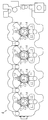
- the top view which shows the planar structure seen from the upper direction of the water jacket formed in the cylinder head of the embodiment.
- the perspective view which shows partially the perspective structure of the water jacket formed in the cylinder head of the embodiment
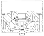
- Sectional drawing which shows the cross-section of the cylinder head of the internal combustion engine which concerns on the 2nd Embodiment of this invention.
- Sectional drawing which shows the effect
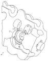
- the inside of the cylinder head 1 has a two-layer structure composed of two decks, a lower deck 2 and an upper deck 3.
- a water jacket 4 through which cooling water flows is formed between the lower deck 2 and the upper deck 3.
- the lower part of the cylinder head 1 is formed with an ignition plug attachment hole 5 for attaching an ignition plug as a member to be cooled, and an intake port 7 and an exhaust port 8.
- each cylinder is provided with one spark plug mounting hole 5, a pair of intake ports 7, and a pair of exhaust ports 8.
- a water jacket 4 having a shape as shown in FIGS. 3 and 4 is formed.
- the water jacket 4 is formed so as to avoid a portion 9 through which the spark plug mounting hole 5 is passed, a portion 10 through which the intake port 7 is passed, and a portion 11 through which the exhaust port 8 is passed.
- the upper surfaces 12 to 14 of the water jacket 4 in the portion between the intake port 7 and the exhaust port 8 and the spark plug mounting hole 5 are arranged around the spark plug mounting hole 5.
- the other portions are formed one step lower than the upper surfaces 15 to 17 of the water jacket 4.
- the cylinder head 1 according to the present embodiment is obtained by omitting a portion C indicated by hatching in FIG. 2 from a similar water jacket of the conventional cylinder head indicated by a dotted line in FIG.
- the lower surface of the cylinder head 1 corresponding to the top surface of the combustion chamber is pushed upward by the in-cylinder pressure generated by combustion.
- a tensile stress is generated in such a direction that the intake port 7 and the exhaust port 8 open outward with the spark plug mounting hole 5 as the center.
- the rigidity of the portion between the intake port 7 and the exhaust port 8 and the spark plug mounting hole 5 is increased, and deformation of the cylinder head 1 at this time is suppressed.
- the stress concentration around the spark plug mounting hole 5 during the in-cylinder pressure action is alleviated.
- the upper surface 12 to 14 of the water jacket 4 around the spark plug mounting hole 5 between the intake port 7 and the exhaust port 8 and the spark plug mounting hole 5 It is made lower than the upper surfaces 15 to 17 of the water jacket 4 in other portions around the hole 5.
- the area around the water jacket 4 in the portion between the intake port 7 and the exhaust port 8 and the spark plug mounting hole 5 is reinforced, and its rigidity is enhanced. Therefore, the deformation of the cylinder head 1 due to the in-cylinder pressure can be suppressed, and the stress concentration around the spark plug mounting hole 5 due to the deformation can be suitably reduced.
- the water jacket 4 is left around the lower portion of the spark plug mounting hole 5 close to the combustion chamber while increasing the rigidity. For this reason, it is possible to maintain the cooling performance of the portion on the combustion chamber side that is at a high temperature, while increasing the rigidity around the spark plug mounting hole 5 to alleviate the stress concentration around the spark plug mounting hole 5.
- a water jacket 21 is also formed in the cylinder head 20 of the present embodiment so that cooling water flows through the periphery of the spark plug mounting hole 5.
- the upper surface of the water jacket 21 is the portion of the water jacket 21 around the spark plug mounting hole 5 even in the portion between the intake / exhaust ports 7 and 8 and the spark plug mounting hole 5. It is formed so as to be the same height as the upper surface.
- the wall surface 21a on the inner peripheral side of the water jacket 21 in the portion between the intake / exhaust ports 7 and 8 and the spark plug mounting hole 5 is reinforced by thickening.
- a portion 22 indicated by hatching in FIG. 5 indicates such a portion where the thickness has been increased.
- the periphery of the spark plug mounting hole 5 immediately above the combustion chamber is pushed up, and the intake port 7 and the exhaust port 8 center on the spark plug mounting hole 5 outward. Transform to open.
- the rigidity of the portion between the intake and exhaust ports 7 and 8 and the spark plug mounting hole 5 is enhanced. Therefore, in the cylinder head 20, deformation due to the action of the in-cylinder pressure is suppressed, and stress concentration around the spark plug mounting hole 5 due to the deformation is also reduced.
- the wall thickness of the water jacket 4 is increased in the portion between the intake port 7 and the exhaust port 8 and the spark plug mounting hole 5.
- the area around the water jacket 4 in the region between the intake port 7 and the exhaust port 8 and the spark plug mounting hole 5 is reinforced, and its rigidity is enhanced. Therefore, the stress concentration around the spark plug mounting hole 5 due to the in-cylinder pressure can be suitably reduced.
- the thickness increase for reinforcing the wall surface of the water jacket 21 is performed on the upper portion of the water jacket 21. For this reason, the water jacket 21 is left as it is without reducing the flow path area in the region close to the combustion chamber while increasing the rigidity of the portion between the intake / exhaust ports 7 and 8 and the spark plug mounting hole 5. It is possible to maintain the cooling performance of the combustion chamber side region.
- the thickening is performed on the inner peripheral side of the water jacket 21 in the portion between the intake / exhaust ports 7 and 8 and the spark plug mounting hole 5. You may make it perform thickening to the outer peripheral side of 21.
- the thickness of the upper portion of the water jacket 21 in the portion between the intake / exhaust ports 7 and 8 and the spark plug mounting hole 5 is increased. If necessary to secure the thickness, the lower wall of the water jacket 21 may be increased in thickness. In order to ensure cooling performance, it is desirable to increase the flow path area under the water jacket 21. Therefore, even when it is necessary to increase the thickness of the water jacket 21 from the upper part to the lower part, the water jacket is designed so that the thickness of the lower part is reduced and the upper part is increased so that the width increases toward the lower part. It is desirable to form 21.
- the upper surface of the water jacket 4 is lowered or the thickness of the water jacket 4 is increased, so that the water jackets 4, 21 in the portion between the intake / exhaust ports 7, 8 and the spark plug mounting hole 5
- the surrounding rigidity was increased.
- Reinforcement for increasing the rigidity of such a part for example, providing a beam or a rib, or forming the periphery of the water jackets 4 and 21 of such part with a material having higher rigidity than other parts, etc.
- other reinforcing methods may be used.
- both the portion between the spark plug mounting hole 5 and the intake port 7 and the portion between the spark plug mounting hole 5 and the exhaust port 8 are reinforced. If it is possible to alleviate stress concentration, reinforcement of either one of them may be omitted.
- the spark plug mounting hole 5 to which the spark plug is mounted is formed.
- an injector may be mounted on the cylinder head instead of the spark plug. Even in such a case, if the reinforcement is performed around the water jacket in the portion between at least one of the intake port and the exhaust port and the injector mounting hole, the stress concentration around the injector mounting hole can be reduced.
- the injector is a member to be cooled.
- a pair of intake ports 7 and a pair of exhaust ports 8 are provided for each cylinder, but the number and arrangement of intake ports 7 and exhaust ports 8 for each cylinder are not limited to this. Instead, it may be changed as appropriate.
Landscapes
- Engineering & Computer Science (AREA)
- Chemical & Material Sciences (AREA)
- Combustion & Propulsion (AREA)
- Mechanical Engineering (AREA)
- General Engineering & Computer Science (AREA)
- Cylinder Crankcases Of Internal Combustion Engines (AREA)
Abstract
Description
以下、本発明の内燃機関のシリンダーヘッドを具体化した第1の実施の形態を、図1~図4を参照して詳細に説明する。なお、本実施の形態のシリンダーヘッドは、直列4気筒配列の内燃機関に適用されるものとなっている。 (First embodiment)
Hereinafter, a first embodiment of a cylinder head of an internal combustion engine according to the present invention will be described in detail with reference to FIGS. Note that the cylinder head of the present embodiment is applied to an in-line four-cylinder arrangement internal combustion engine.
続いて、本発明の内燃機関のシリンダーヘッドを具体化した第2の実施の形態を、図5を参照して詳細に説明する。なお、本実施の形態のシリンダーヘッドは、第1の実施の形態のシリンダーヘッドに対して、点火プラグ取付孔5の周囲に形成されるウォータージャケットの形状を変更しただけのものとなっている。そこで、本実施の形態では、第1の実施の形態のものと共通する構成については、同一の符号を付してその詳細な説明は省略する。 (Second Embodiment)
Next, a second embodiment in which the cylinder head of the internal combustion engine of the present invention is embodied will be described in detail with reference to FIG. In addition, the cylinder head of this Embodiment is a thing which only changed the shape of the water jacket formed in the circumference | surroundings of the spark
Claims (6)
- 吸気ポート、排気ポート、被冷却部材を取り付けるための取付孔、及びその取付孔の周囲に設けられたウォータージャケットを備える内燃機関のシリンダーヘッドにおいて、
前記吸気ポート及び前記排気ポートの少なくとも一方と前記取付孔との間の部分における前記ウォータージャケットの周りの剛性が、前記取付孔の周囲のそれ以外の部分における前記ウォータージャケットの周りの剛性よりも高くされてなる
ことを特徴とする内燃機関のシリンダーヘッド。 In a cylinder head of an internal combustion engine including an intake port, an exhaust port, a mounting hole for mounting a member to be cooled, and a water jacket provided around the mounting hole,
Rigidity around the water jacket in a portion between at least one of the intake port and the exhaust port and the attachment hole is higher than rigidity around the water jacket in other portions around the attachment hole. A cylinder head of an internal combustion engine characterized by being made. - 吸気ポート、排気ポート、被冷却部材を取り付けるための取付孔、及びその取付孔の周囲に設けられたウォータージャケットを備える内燃機関のシリンダーヘッドにおいて、
前記吸気ポート及び前記排気ポートの少なくとも一方と前記取付孔との間の部分における前記ウォータージャケットの周りには、剛性を高めるための補強がなされてなる
ことを特徴とする内燃機関のシリンダーヘッド。 In a cylinder head of an internal combustion engine including an intake port, an exhaust port, a mounting hole for mounting a member to be cooled, and a water jacket provided around the mounting hole,
A cylinder head for an internal combustion engine, wherein reinforcement for increasing rigidity is provided around the water jacket in a portion between at least one of the intake port and the exhaust port and the mounting hole. - 前記補強は、前記吸気ポート及び前記排気ポートの少なくとも一方と前記取付孔との間の部分の前記ウォータージャケットの上面を、前記取付孔の周囲のそれ以外の部分の前記ウォータージャケットの上面よりも低くすることでなされてなる
請求項2に記載の内燃機関のシリンダーヘッド。 The reinforcement is such that the upper surface of the water jacket in a portion between at least one of the intake port and the exhaust port and the mounting hole is lower than the upper surface of the water jacket in other portions around the mounting hole. The cylinder head of the internal combustion engine according to claim 2, which is made by: - 前記補強は、前記ウォータージャケットの周囲の壁面に増肉を行うことでなされてなる
請求項2に記載の内燃機関のシリンダーヘッド。 The cylinder head of the internal combustion engine according to claim 2, wherein the reinforcement is performed by increasing the thickness of a wall surface around the water jacket. - 吸気ポート、排気ポート、被冷却部材を取り付けるための取付孔、及びその取付孔の周囲に設けられたウォータージャケットを備える内燃機関のシリンダーヘッドにおいて、
前記吸気ポート及び前記排気ポートの少なくとも一方と前記取付孔との間の部分の前記ウォータージャケットの上面は、前記取付孔の周囲のそれ以外の部分の前記ウォータージャケットの上面よりも低くされてなる
ことを特徴とする内燃機関のシリンダーヘッド。 In a cylinder head of an internal combustion engine including an intake port, an exhaust port, a mounting hole for mounting a member to be cooled, and a water jacket provided around the mounting hole,
The upper surface of the water jacket at a portion between at least one of the intake port and the exhaust port and the mounting hole is made lower than the upper surface of the water jacket at other portions around the mounting hole. A cylinder head of an internal combustion engine characterized by - 吸気ポート、排気ポート、被冷却部材を取り付けるための取付孔、及びその取付孔の周囲に設けられたウォータージャケットを備える内燃機関のシリンダーヘッドにおいて、
前記吸気ポート及び前記排気ポートの少なくとも一方と前記取付孔との間の部分における前記ウォータージャケットの壁面に増肉がなされてなる
ことを特徴とする内燃機関のシリンダーヘッド。 In a cylinder head of an internal combustion engine including an intake port, an exhaust port, a mounting hole for mounting a member to be cooled, and a water jacket provided around the mounting hole,
A cylinder head of an internal combustion engine, wherein a wall thickness of the water jacket is increased in a portion between at least one of the intake port and the exhaust port and the mounting hole.
Priority Applications (9)
| Application Number | Priority Date | Filing Date | Title |
|---|---|---|---|
| RU2013149564/06A RU2552018C1 (en) | 2011-04-11 | 2011-04-11 | Internal combustion engine cylinder head |
| CN201180069978.8A CN103459814B (en) | 2011-04-11 | 2011-04-11 | The cylinder head of internal-combustion engine |
| US14/110,606 US8904975B2 (en) | 2011-04-11 | 2011-04-11 | Cylinder head of internal combustion engine |
| PCT/JP2011/059024 WO2012140722A1 (en) | 2011-04-11 | 2011-04-11 | Cylinder head of internal combustion engine |
| BR112013026053A BR112013026053A2 (en) | 2011-04-11 | 2011-04-11 | internal combustion engine head |
| EP11863558.0A EP2698522B1 (en) | 2011-04-11 | 2011-04-11 | Cylinder head of internal combustion engine |
| JP2013509683A JP5692364B2 (en) | 2011-04-11 | 2011-04-11 | Cylinder head of internal combustion engine |
| KR1020137028412A KR20130127546A (en) | 2011-04-11 | 2011-04-11 | Cylinder head of internal combustion engine |
| AU2011365254A AU2011365254B2 (en) | 2011-04-11 | 2011-04-11 | Cylinder head of internal combustion engine |
Applications Claiming Priority (1)
| Application Number | Priority Date | Filing Date | Title |
|---|---|---|---|
| PCT/JP2011/059024 WO2012140722A1 (en) | 2011-04-11 | 2011-04-11 | Cylinder head of internal combustion engine |
Publications (1)
| Publication Number | Publication Date |
|---|---|
| WO2012140722A1 true WO2012140722A1 (en) | 2012-10-18 |
Family
ID=47008933
Family Applications (1)
| Application Number | Title | Priority Date | Filing Date |
|---|---|---|---|
| PCT/JP2011/059024 WO2012140722A1 (en) | 2011-04-11 | 2011-04-11 | Cylinder head of internal combustion engine |
Country Status (9)
| Country | Link |
|---|---|
| US (1) | US8904975B2 (en) |
| EP (1) | EP2698522B1 (en) |
| JP (1) | JP5692364B2 (en) |
| KR (1) | KR20130127546A (en) |
| CN (1) | CN103459814B (en) |
| AU (1) | AU2011365254B2 (en) |
| BR (1) | BR112013026053A2 (en) |
| RU (1) | RU2552018C1 (en) |
| WO (1) | WO2012140722A1 (en) |
Families Citing this family (6)
| Publication number | Priority date | Publication date | Assignee | Title |
|---|---|---|---|---|
| JP2016138461A (en) * | 2015-01-26 | 2016-08-04 | トヨタ自動車株式会社 | Cylinder head and manufacturing method of cylinder head |
| US10202888B2 (en) | 2015-12-08 | 2019-02-12 | Ford Global Technologies, Llc | Engine air path cooling system |
| JP6562013B2 (en) * | 2017-02-16 | 2019-08-21 | トヨタ自動車株式会社 | cylinder head |
| RU2704708C2 (en) * | 2017-08-24 | 2019-10-30 | Акционерное общество "АвтоВАЗ" | Internal combustion engine cylinder block head |
| CN112502847A (en) * | 2020-11-27 | 2021-03-16 | 潍柴动力股份有限公司 | Engine cylinder cover and natural gas engine |
| US11459975B1 (en) * | 2021-07-06 | 2022-10-04 | Caterpillar Inc. | Cylinder head having cast-in coolant passages arranged for passive igniter cooling |
Citations (5)
| Publication number | Priority date | Publication date | Assignee | Title |
|---|---|---|---|---|
| JP2003310157A (en) | 2002-04-17 | 2003-11-05 | Keiki Rin | Method for processing tea leaf |
| JP2004218481A (en) | 2003-01-10 | 2004-08-05 | Isuzu Motors Ltd | Cylinder head inside cooling structure for multi-cylinder internal combustion engine |
| JP4157714B2 (en) * | 2002-03-06 | 2008-10-01 | ヤンマー株式会社 | Engine heat exchanger |
| JP2009197725A (en) * | 2008-02-22 | 2009-09-03 | Nissan Motor Co Ltd | Cylinder head of internal combustion engine |
| JP2009264260A (en) | 2008-04-25 | 2009-11-12 | Toyota Motor Corp | Cooling water passage structure of cylinder head |
Family Cites Families (15)
| Publication number | Priority date | Publication date | Assignee | Title |
|---|---|---|---|---|
| US1338342A (en) * | 1917-04-09 | 1920-04-27 | Waukesha Motor Co | Internal-combustion engine |
| JP3280489B2 (en) | 1993-09-30 | 2002-05-13 | マツダ株式会社 | Engine cylinder head structure and method of manufacturing the same |
| DE19737492C1 (en) * | 1997-08-28 | 1998-10-29 | Daimler Benz Ag | Liquid cooled cylinder head for motor vehicle internal combustion engine |
| JP4199355B2 (en) * | 1999-02-09 | 2008-12-17 | トヨタ自動車株式会社 | Cylinder head of internal combustion engine |
| JP2000310157A (en) | 1999-04-27 | 2000-11-07 | Mazda Motor Corp | Cylinder head structure for multiple cylinder engine |
| JP2002256966A (en) | 2001-03-06 | 2002-09-11 | Toyota Motor Corp | Cooling structure of cylinder head |
| US20020124815A1 (en) * | 2001-03-06 | 2002-09-12 | Toyota Jidosha Kabushiki Kaisha | Cooling structure of cylinder head and method for manufacturing cylinder head |
| JP3916056B2 (en) * | 2002-04-11 | 2007-05-16 | いすゞ自動車株式会社 | cylinder head |
| DE20216452U1 (en) * | 2002-10-25 | 2002-12-19 | Fev Motorentech Gmbh | Cylinder head for a water-cooled piston internal combustion engine with internal reinforcement |
| JP4112391B2 (en) * | 2003-02-06 | 2008-07-02 | 本田技研工業株式会社 | Cylinder head of internal combustion engine |
| JP2005264765A (en) * | 2004-03-16 | 2005-09-29 | Mazda Motor Corp | Cylinder head structure of engine |
| JP4375261B2 (en) | 2005-03-18 | 2009-12-02 | マツダ株式会社 | Cylinder head and water-cooled engine using the same |
| KR100747272B1 (en) * | 2006-02-21 | 2007-08-07 | 현대자동차주식회사 | Water jacket structure of a cylinder head of vehicle |
| US7520257B2 (en) * | 2006-04-13 | 2009-04-21 | Caterpillar Inc. | Engine cylinder head |
| FR2906571B1 (en) * | 2006-10-02 | 2012-01-06 | Renault Sas | CULASSE WITH INSERTS FOR INTERNAL COMBUSTION ENGINES |
-
2011
- 2011-04-11 KR KR1020137028412A patent/KR20130127546A/en active Search and Examination
- 2011-04-11 AU AU2011365254A patent/AU2011365254B2/en not_active Ceased
- 2011-04-11 BR BR112013026053A patent/BR112013026053A2/en not_active Application Discontinuation
- 2011-04-11 WO PCT/JP2011/059024 patent/WO2012140722A1/en active Application Filing
- 2011-04-11 US US14/110,606 patent/US8904975B2/en not_active Expired - Fee Related
- 2011-04-11 JP JP2013509683A patent/JP5692364B2/en not_active Expired - Fee Related
- 2011-04-11 EP EP11863558.0A patent/EP2698522B1/en not_active Not-in-force
- 2011-04-11 RU RU2013149564/06A patent/RU2552018C1/en not_active IP Right Cessation
- 2011-04-11 CN CN201180069978.8A patent/CN103459814B/en not_active Expired - Fee Related
Patent Citations (5)
| Publication number | Priority date | Publication date | Assignee | Title |
|---|---|---|---|---|
| JP4157714B2 (en) * | 2002-03-06 | 2008-10-01 | ヤンマー株式会社 | Engine heat exchanger |
| JP2003310157A (en) | 2002-04-17 | 2003-11-05 | Keiki Rin | Method for processing tea leaf |
| JP2004218481A (en) | 2003-01-10 | 2004-08-05 | Isuzu Motors Ltd | Cylinder head inside cooling structure for multi-cylinder internal combustion engine |
| JP2009197725A (en) * | 2008-02-22 | 2009-09-03 | Nissan Motor Co Ltd | Cylinder head of internal combustion engine |
| JP2009264260A (en) | 2008-04-25 | 2009-11-12 | Toyota Motor Corp | Cooling water passage structure of cylinder head |
Non-Patent Citations (1)
| Title |
|---|
| See also references of EP2698522A4 * |
Also Published As
| Publication number | Publication date |
|---|---|
| RU2013149564A (en) | 2015-05-20 |
| BR112013026053A2 (en) | 2017-02-14 |
| EP2698522B1 (en) | 2015-12-30 |
| US8904975B2 (en) | 2014-12-09 |
| RU2552018C1 (en) | 2015-06-10 |
| JP5692364B2 (en) | 2015-04-01 |
| KR20130127546A (en) | 2013-11-22 |
| EP2698522A1 (en) | 2014-02-19 |
| CN103459814A (en) | 2013-12-18 |
| AU2011365254B2 (en) | 2015-11-05 |
| EP2698522A4 (en) | 2014-10-08 |
| JPWO2012140722A1 (en) | 2014-07-28 |
| US20140076262A1 (en) | 2014-03-20 |
| CN103459814B (en) | 2015-12-09 |
| AU2011365254A1 (en) | 2013-10-31 |
Similar Documents
| Publication | Publication Date | Title |
|---|---|---|
| JP5692364B2 (en) | Cylinder head of internal combustion engine | |
| KR101463800B1 (en) | Gasket | |
| JPH11117803A (en) | Cylinder head structure for internal combustion engine | |
| JP2002070642A (en) | Cylinder head for multicylinder engine | |
| KR20090087418A (en) | Cylinder head gasket and method of designing cylinder head gasket | |
| JP2015117619A (en) | Cylinder head | |
| JP2010151063A (en) | Cylinder block | |
| JP5488745B2 (en) | Cylinder block | |
| JP5141933B2 (en) | Exhaust manifold | |
| JP2007309188A (en) | Cylinder head for internal combustion engine | |
| JP4475327B2 (en) | Bracket fastening structure | |
| JP2008150960A (en) | Cylinder block for multi-cylinder internal combustion engine | |
| CN113530699B (en) | Cylinder block | |
| JP6461199B2 (en) | Internal combustion engine | |
| US9422854B2 (en) | Exhaust gas evacuation system structure for internal combustion engine | |
| JP2008190357A (en) | Piston | |
| JP2018059440A (en) | Heat bolt arrangement of engine, and core of water jacket of cylinder head | |
| JP2004092620A (en) | Cylinder head of internal combustion engine | |
| JP2021101109A (en) | Internal combustion engine, saddle-riding type vehicle and method for manufacturing internal combustion engine | |
| JPH0110422Y2 (en) | ||
| JPH0218418B2 (en) | ||
| WO2016067653A1 (en) | Cylinder head and internal combustion engine equipped with same | |
| WO2016001989A1 (en) | Internal combustion engine | |
| JP2013144968A (en) | Mounting structure of exhaust system component | |
| JP2011157847A (en) | Multi-cylinder engine |
Legal Events
| Date | Code | Title | Description |
|---|---|---|---|
| 121 | Ep: the epo has been informed by wipo that ep was designated in this application |
Ref document number: 11863558 Country of ref document: EP Kind code of ref document: A1 |
|
| ENP | Entry into the national phase |
Ref document number: 2013509683 Country of ref document: JP Kind code of ref document: A |
|
| WWE | Wipo information: entry into national phase |
Ref document number: 14110606 Country of ref document: US |
|
| NENP | Non-entry into the national phase |
Ref country code: DE |
|
| ENP | Entry into the national phase |
Ref document number: 20137028412 Country of ref document: KR Kind code of ref document: A |
|
| WWE | Wipo information: entry into national phase |
Ref document number: 2011863558 Country of ref document: EP |
|
| ENP | Entry into the national phase |
Ref document number: 2011365254 Country of ref document: AU Date of ref document: 20110411 Kind code of ref document: A |
|
| ENP | Entry into the national phase |
Ref document number: 2013149564 Country of ref document: RU Kind code of ref document: A |
|
| REG | Reference to national code |
Ref country code: BR Ref legal event code: B01A Ref document number: 112013026053 Country of ref document: BR |
|
| ENP | Entry into the national phase |
Ref document number: 112013026053 Country of ref document: BR Kind code of ref document: A2 Effective date: 20131009 |