WO2012137455A1 - 音声処理装置、音声データ処理方法、音声データ処理プログラム - Google Patents
音声処理装置、音声データ処理方法、音声データ処理プログラム Download PDFInfo
- Publication number
- WO2012137455A1 WO2012137455A1 PCT/JP2012/002245 JP2012002245W WO2012137455A1 WO 2012137455 A1 WO2012137455 A1 WO 2012137455A1 JP 2012002245 W JP2012002245 W JP 2012002245W WO 2012137455 A1 WO2012137455 A1 WO 2012137455A1
- Authority
- WO
- WIPO (PCT)
- Prior art keywords
- data
- control information
- unit
- pulse code
- code modulation
- Prior art date
- Legal status (The legal status is an assumption and is not a legal conclusion. Google has not performed a legal analysis and makes no representation as to the accuracy of the status listed.)
- Ceased
Links
Images





Classifications
-
- G—PHYSICS
- G10—MUSICAL INSTRUMENTS; ACOUSTICS
- G10L—SPEECH ANALYSIS TECHNIQUES OR SPEECH SYNTHESIS; SPEECH RECOGNITION; SPEECH OR VOICE PROCESSING TECHNIQUES; SPEECH OR AUDIO CODING OR DECODING
- G10L19/00—Speech or audio signals analysis-synthesis techniques for redundancy reduction, e.g. in vocoders; Coding or decoding of speech or audio signals, using source filter models or psychoacoustic analysis
- G10L19/008—Multichannel audio signal coding or decoding using interchannel correlation to reduce redundancy, e.g. joint-stereo, intensity-coding or matrixing
-
- H—ELECTRICITY
- H03—ELECTRONIC CIRCUITRY
- H03M—CODING; DECODING; CODE CONVERSION IN GENERAL
- H03M7/00—Conversion of a code where information is represented by a given sequence or number of digits to a code where the same, similar or subset of information is represented by a different sequence or number of digits
- H03M7/30—Compression; Expansion; Suppression of unnecessary data, e.g. redundancy reduction
- H03M7/3053—Block-companding PCM systems
Definitions
- the present invention relates to a voice processing device, a voice data processing method, and a voice data processing program.
- the audio processing apparatus generally includes an audio digital signal processor (Digital-Signal-Processor, hereinafter referred to as DSP) and a digital / analog converter (Digital-Analog-Converter, hereinafter referred to as DAC).
- DSP Digital-Signal-Processor
- DAC Digital-Analog-Converter
- FIG. 11 is a block diagram showing a configuration of a general audio processing apparatus.
- the DSP 30 includes an audio data decoding unit 310, a control unit 320, a PCM data output unit 330, and a control information output unit 340.
- the DAC 40 includes a PCM data input unit 410, a control information input unit 420, a PCM data control unit 430, and a D / A conversion unit 440.
- the audio data decoding unit 310 receives an encoded stream that is audio data.
- the audio data decoding unit 310 decodes the encoded stream using the decoding control information input from the control unit 320 and supplies PCM data as a decoding result to the PCM data output unit 330.
- the PCM data output unit 330 converts PCM data into a three-wire serial communication signal and supplies the converted signals (LRCK, BCK, DATA) to the PCM data input unit 410.
- the PCM data input unit 410 supplies the input PCM data to the PCM data control unit 430.
- the control unit 320 outputs control information of PCM data (hereinafter referred to as PCM control information) to the control information output unit 340.
- PCM control information control information of PCM data
- the control information output unit 340 supplies a signal (MS, MC, MD) obtained by converting the PCM control information into an SPI (Serial Peripheral Interface) format or the like to the control information input unit 420.
- the control information input unit 420 writes the supplied PCM control information in the control information register 431 in the PCM data control unit 430.
- the PCM data control unit 430 processes the supplied PCM data according to the setting of the control information register 431.
- the PCM data control unit 430 supplies the PCM data after the processing to the D / A conversion unit 440.
- the D / A conversion unit 440 converts the supplied PCM data into an L channel audio analog signal or an R channel audio analog signal, and supplies the converted analog signal to an arbitrary processing unit (not shown).
- L-channel data and R-channel data are alternately transmitted every 32 bits (every time BCK (base clock) rises 32 times).
- BCK base clock
- 16-bit to 24-bit PCM data is packed on the MSB (Most Significant Bit) side and transmitted.
- the L channel data (DATA) and the R channel data (DATA) include an unused area of 8 to 16 bits.
- the PCM data supplied from the audio decoding unit 310 is divided into 16 bits to 24 bits and transmitted as appropriate.
- PCM control information transmitted and received between the control information output unit 340 and the control information input unit 420 will be described with reference to FIG.
- the PCM control information transmitted and received between the two is, for example, an SPI format signal.
- SPI format signal is transmitted and received.
- the MS signal is a signal indicating whether or not the MD signal is PCM control information. While the MS signal is at a low level, it indicates that the MD signal is PCM control information.
- the PCM control information is 8-bit information in this example.
- the PCM control information includes an unused area (1 bit, “Rsv”), an index (3 bits, “IDX”) of the control information register 431, a set value (4 bits, “Bit”) in the control information register, Including.
- the index of the control information register 431 is information indicating the address of a register in the control information register 431.
- FIG. 15 shows a correspondence example between the set value of the control information register and the control content.
- 14-bit PCM control information shown in FIG. 14 (0) is information for setting whether or not to make a silent output for the register 0. As shown in FIG. 15, when 0 is set in Bit0, the silence output is set to OFF. Similarly, when 1 is set in Bit0, the silence output is set to ON. In FIG. 14, since 0 is set in Bit0, the silent output is set to OFF. In the 8-bit PCM control information shown in FIG. 14 (0), an unused area ("Rsv") for 3 bits is secured.
- the 8-bit PCM control information shown in FIG. 14 (1) is information for making any setting other than silence output for the register 1.
- the 8-bit PCM control information shown in FIGS. 14 (2) to (7) is information for making any setting other than silent output for the registers 2 to 7.
- FIG. 14 (0) is information for setting whether or not to make a silent output for the register 0. As shown in FIG. 15, when 0 is set in Bit0, the silence output is set to OFF. Similarly, when 1 is set in Bit0,
- Patent Document 1 discloses a technique for handling transmission / reception of PCM data shown in FIGS.
- FIG. 16 is a block diagram showing the configuration of the remote control device described in Patent Document 1.
- the video / audio signal processing circuit 52 extracts a digital video signal and a digital audio signal from the signal input from the tuner 53.
- the video / audio signal processing circuit 52 supplies the digital audio signal to the DAC 54.
- the CPU 55 supplies control information to the DAC 54.
- the DAC 54 converts the digital audio signal input from the video / audio signal processing circuit 52 into an analog audio signal, and outputs the analog audio signal to the audio signal output terminal 57. Audio signal processing in the DAC 54 is performed according to control information supplied from the CPU 55.
- Patent Document 2 when an ADPCM format audio data stream is transmitted, an empty area is generated in the stream by switching the mode from 4-bit encoding to 3-bit encoding, and control information is stored in the empty area.
- a technique for inserting and transmitting a message is disclosed.
- Patent Document 3 discloses a technique regarding a sound data processing apparatus that performs processing at an accurate timing by giving processing cues to PCM data and referring to the processing cues. However, there is no suggestion regarding separation of PCM data and processing cues and data transfer between devices.
- a communication interface related to an audio signal and a communication interface related to control information are required. That is, an input / output terminal for audio signals and an input / output terminal for control information are required.
- input / output terminals are required between the DAC 54 and the CPU 55 and between the DAC 54 and the video / audio signal processing circuit 52.
- the above-described technique has a problem that PCM data and control information cannot be transmitted without causing data degradation with a small configuration.
- One aspect of the speech processing apparatus is: A first device for generating and outputting superposition format data in which control information of the pulse code modulation data is inserted into an empty area of unit data including pulse code modulation data obtained by decoding the encoded stream; A second device that separates the superimposition format data into the pulse code modulation data and the control information, and executes a control process on the pulse code modulation data based on the control information. is there.
- An audio data processing method for transmitting and receiving information on a code stream between a first device and a second device The first device generates and outputs superimposition format data in which control information of the pulse code modulation data is inserted in an empty area of unit data including pulse code modulation data obtained by decoding the encoded stream, The second device separates the superimposition format data into the pulse code modulation data and the control information, and executes a control process on the pulse code modulation data based on the control information.
- a program for generating data for generating data for transmitting an encoded stream The generation process is to generate superimposition format data in which control information of the pulse code modulation data is inserted into an empty area of unit data including pulse code modulation data obtained by decoding the encoded stream.
- the superimposition format data is generated by inserting control information into the empty area, and the superimposition format data is transmitted and received between the first device and the second device. Since the control information is inserted into the empty area, no data loss of the pulse code modulation data occurs. Further, since the pulse code modulation data and the control information are superimposed, the number of input / output terminals used for transmission and reception can be reduced, and the apparatus can be downsized.
- an audio processing device an audio data processing method, and an audio data processing program capable of transmitting PCM data and control information with a small configuration without causing data deterioration.
- FIG. 1 is a block diagram illustrating a configuration of a speech processing apparatus according to a first embodiment.
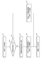
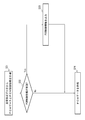
- 3 is a flowchart illustrating an operation of a superimposition processing unit according to the first exemplary embodiment. It is a figure which shows the communication data transmitted / received between the output part concerning Embodiment 1, and an input part.
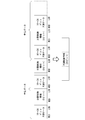
- FIG. 3 is a conceptual diagram showing details of L channel unit data and R channel unit data according to the first exemplary embodiment
- FIG. 3 is a conceptual diagram showing details of L channel unit data and R channel unit data according to the first exemplary embodiment
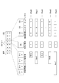
- FIG. 3 is a conceptual diagram showing details of PCM control information according to the first exemplary embodiment.
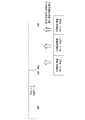
- FIG. 3 is a flowchart showing an operation of a separation processing unit according to the first exemplary embodiment; It is a figure which shows the superimposition format data concerning Embodiment 2.
- FIG. It is a conceptual diagram which shows the PCM control information concerning Embodiment 3.
- FIG. 1 is a block diagram showing the configuration of the speech processing apparatus according to this embodiment.
- the audio processing apparatus 1 includes a DSP (Digital Signal Processor) 10 and a DAC (Digital / Analog Converter) 20.
- the DSP 10 includes an audio data decoding unit 110, a control unit 120, a superimposition processing unit 130, and an output unit 140.
- the DAC 20 includes an input unit 210, a separation processing unit 220, a PCM data control unit 230, and a D / A conversion unit 240. In this example, transmission / reception is performed between the output unit 140 and the input unit 210 by three-wire serial communication.
- the audio data decoding unit 110 receives an encoded stream that is audio data.
- the audio data decoding unit 110 decodes the encoded stream using the decoding control information input from the control unit 120 and supplies PCM data as a decoding result to the superimposition processing unit 130.
- the control unit 120 supplies the audio data decoding unit 110 with decode control information used for decoding. Further, the control unit 120 supplies control information for the PCM data (hereinafter referred to as PCM control information) to the superimposition processing unit 130.
- PCM control information control information for the PCM data (hereinafter referred to as PCM control information) to the superimposition processing unit 130.
- the superposition processing unit 130 generates data obtained by superimposing the input PCM data and the PCM control information (hereinafter referred to as superposition format data). More specifically, the superimposition processing unit 130 generates superimposition format data by embedding PCM control information in an unused area in a 3-wire serial communication signal. The superimposition processing unit 130 supplies the generated superimposition format data to the output unit 140. Details of the superposition format data and the generation method will be described later with reference to FIGS.
- the output unit 140 is a processing unit that transmits superimposition format data to the input unit 210 in the DAC 20 via a three-wire serial interface.
- the superposition format data in which the PCM data and the PCM control information are superposed is input to the input unit 210 via a three-wire serial interface.
- the input unit 210 supplies the input superimposition format data to the separation processing unit 220.
- the separation processing unit 220 separates PCM data and PCM control information from the superimposition format data.
- the separation processing unit 220 supplies the separated PCM data to the PCM control unit 230. Further, the separation processing unit 220 writes the separated PCM control information in the control information register 231.
- the PCM data control unit 230 processes the supplied PCM data according to the setting of the control information register 231.
- the control information register 231 generally has a plurality of registers, and reads and processes necessary registers according to the settings of the DAC 20.
- the PCM data control unit 230 supplies the PCM data after the processing to the D / A conversion unit 240.
- the D / A converter 240 converts the supplied PCM data into an audio analog signal for the L channel or an audio analog signal for the R channel based on a commonly used method such as a ladder resistance method.
- the D / A converter 240 supplies the converted audio analog signal to an arbitrary processor.
- FIG. 2 is a flowchart showing the operation of the superimposition processing unit 130.
- the superimposition processing unit 130 is supplied with PCM data from the audio data decoding unit 110 (S11).
- the superimposition processing unit 130 determines whether PCM control information is input from the control unit 120 (S12).
- the superimposition processing unit 130 sets the PCM control information to invalid (S13).
- the superimposition processing unit 130 generates superimposition format data in which the invalidated PCM control information and PCM data are superimposed (S14).
- the superimposition processing unit 130 when it is determined that the PCM control information is input (S12: Yes), the superimposition processing unit 130 generates superimposition format data in which the PCM data and the PCM control information are superimposed (S15).
- the superimposition processing unit 130 supplies the superimposition format data to the output unit 140 (S16).
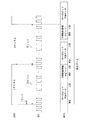
- L channel data and R channel data are transmitted alternately.
- the data for the L channel and the data for the R channel are audio data at the same timing.
- the data for the L channel and the data for the R channel are both referred to as unit data.
- the L channel data constituting the unit data is referred to as L channel unit data
- the R channel data is referred to as R channel unit data.
- PCM data 16 to 24 bits are stored in the L channel unit data and the R channel unit data from the MSB (Most Significant Bit) side. Furthermore, 8-bit PCM control information is stored from the LSB (LeastRSignificant Bit) side in the L channel unit data and the R channel unit data. As described above, the superimposition format data in which the PCM data and the PCM control information are superimposed is generated by the above-described superimposition processing unit 130.
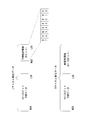
- FIG. 4 and 5 are conceptual diagrams showing details of L channel unit data and R channel unit data.
- the PCM control information is composed of 8-bit information in this example.
- FIG. 5 a plurality (two in the example of FIG. 5) of PCM control information is inserted into L channel unit data, or PCM control information is added to both L channel unit data and R channel unit data. It is also possible to insert.
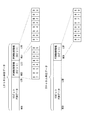
- the PCM control information includes 1 bit (EN) indicating validity / invalidity, 3 bits (IDX0 to IDX2) indicating an index of the control information register 231, and 4 bits (Bit0 to Bit3) indicating a set value in the control information register 231. Is composed of.
- 0 or 1 is set in 1 bit (EN) indicating valid / invalid.
- EN 1 bit
- the index (IDX0 to IDX2) of the control information register 231 is information indicating which register in the control information register 231 is set.
- the control information register 231 includes eight setting registers Reg0 to Reg7.
- the set values (Bit0 to Bit3) in the control information register 231 are various settings related to voice processing. Each set value does not have to be 4-bit information. For example, as shown in FIG. 6, the silence setting (Mute) is 1-bit information. In this case, information (Rsv) indicating an unused area is inserted into each bit not used for setting.
- FIG. 6 is merely an example of PCM control information, and the size of the index of the control information register 231 and the size of the set value in the control information register 231 can be changed as appropriate.
- FIG. 7 is a flowchart showing the operation of the separation processing unit 220.
- Superimposition format data is input from the input unit 210 to the separation processing unit 220.
- the separation processing unit 220 separates the superimposition format data into PCM data and PCM control information (S21).
- the separation processing unit 220 obtains PCM data by extracting 16 to 24 bits from the MSB side of the L channel unit data or the R channel unit data. Further, the separation processing unit 220 acquires PCM control information by extracting 8 bits from the LSB side of the L channel unit data or the R channel unit data.
- the separation processing unit 220 determines whether or not the other PCM control information to be extracted is valid (S22).
- the separation processing unit 220 determines validity / invalidity based on the value of a bit indicating validity / invalidity in the PCM control information.
- the separation processing unit 220 When the PCM control information is valid (S22: Yes), the separation processing unit 220 writes the PCM control information in the control information register 231 (S23). After the writing, the separation processing unit 220 supplies the PCM data to the D / A conversion unit 240 (S24).
- the separation processing unit 220 does not write data to the control information register 231 and supplies PCM data to the D / A conversion unit 240 (S24).
- the superimposition format data is generated by inserting the PCM control information into the empty area, and the superimposition format data is transmitted and received between the DSP 10 and the DAC 20. Since the PCM control information is inserted into the empty area, data loss of PCM data does not occur. In addition, since the superimposition format data in which the PCM data and the PCM control information are superimposed is transmitted / received, the number of input / output terminals used for transmission / reception can be reduced, and the apparatus can be downsized.
- the processing of the superimposition processing unit 130 and the separation processing unit 220 can be realized as a program operated by the CPU. For this reason, the processing unit does not increase the scale of the apparatus.
- the superimposition processing unit 130 inserts PCM control information in order from the LSB side of each channel unit data.
- the separation processing unit 220 can obtain a fixed length (8 bits in the above example) from the unit data for each channel and mechanically determine the validity and the like. That is, since the place where the PCM control information is inserted is a position suitable for mechanical processing, the separation processing unit 220 can process the PCM control information appropriately and at high speed.
- the superimposition processing unit 130 inserts information indicating validity / invalidity in the PCM control information.
- the separation processing unit 220 does not have a risk of performing an erroneous operation such as writing the PCM control information to the control register 231 even though the PCM control information is not inserted.
- a plurality of PCM control information can be included in the unit data. Thereby, even when it is necessary to frequently change the settings regarding the audio processing, the separation processing unit 220 can rewrite the control information register 231 with high frequency.
- the speech processing apparatus 1 according to the second embodiment is characterized in that the PCM control information is divided and the divided PCM control information is inserted into a plurality of unit data.
- the speech processing apparatus according to the present embodiment differences from the first embodiment will be described.
- the configuration of the speech processing apparatus according to the second embodiment is the same as the configuration shown in FIG.
- the superimposition processing unit 130 divides PCM control information having a size larger than the unit data free area, and inserts the divided PCM control information into a plurality of unit data free areas.
- FIG. 8 is a conceptual diagram showing superposition format data according to the present embodiment. In this example, 24-bit PCM control information is targeted.
- the superimposition processing unit 130 divides the PCM control information supplied from the control unit 120 into three. Then, the superimposition processing unit 130 inserts the PCM control information divided from the LSB side of the L channel unit data and the R channel unit data in a certain unit data. Further, the superimposition processing unit 130 inserts the PCM control information divided from the LSB side of the L channel unit data in the unit data subsequent to the unit data. Then, the superimposition processing unit 130 supplies the superimposition format data to the output unit 140. Other processes in the DSP 10 are the same as those in the first embodiment.
- the separation processing unit 220 extracts 8 bits from the LSB side of the L channel unit data and the R channel unit data, and when a bit indicating validity is set for each, 8 bits from the LSB side of the L channel unit data are It is determined as the head data of the divided PCM control information. Then, the separation processing unit 220 extracts 8 bits from the L channel unit data subsequent to the unit data. Then, the separation processing unit 220 restores the PCM control information by connecting the three divided PCM control information (8 bits). Other processes in the DAC 20 are the same as those in the first embodiment.
- the speech processing apparatus can handle large-size PCM control information straddling unit data.
- PCM control information having a large data size due to complicated setting of the registers, PCM control information having a large data size due to a large number of registers in the control information register 231, and the like.
- the PCM control information is divided into three, but the number of divisions may be any number.
- the superimposition processing unit 130 inserts information indicating whether the PCM control information is related to the division into the divided PCM control information, and the separation processing unit 220 uses the information to divide the PCM control information. May be restored.
- the speech processing apparatus 1 according to the present embodiment is characterized by handling PCM control information of different data sizes. Differences from the first embodiment regarding the speech processing apparatus 1 according to the present embodiment will be described.
- FIG. 9 is a diagram showing PCM control information according to the present embodiment. As shown in the figure, the PCM control information is arranged from the LSB side in the order of control information register index (IDX0 to IDX2), valid / invalid information (EN), and set values (Bit0 to Bit3) in the control information register 231. Is done.
- the data size of the setting value in the control information register 231 differs depending on the value of the control information register index.
- the set value for Reg0 is 1-bit information.
- the set value for Reg1 is 2-bit information.
- the superposition processing unit 130 inserts PCM control information in order from the LSB side of the L channel unit data or the R channel unit data.
- FIG. 10 shows an example of insertion.
- the PCM data included in the L channel unit data and the R channel unit data has a data size of 16 bits.
- the superimposition processing unit 130 inserts PCM control information of different data sizes in order from the LSB side into the empty area.
- the separation processing unit 220 reads information from the LSB side of the L channel unit data or the R channel unit data.
- the separation processing unit 220 grasps the data size of the PCM control information according to the read control information register index (IDX0 to IDX2). For example, when the control information register index is “000”, the separation processing unit 220 determines that the data size of the PCM control information is 5 bits.
- the separation processing unit 220 reads and analyzes certain PCM control information, and then reads the next PCM control information from the same L (R) channel unit data.
- the PCM control information does not include a reserved area having no information. That is, the data size of the PCM control information can be kept small. Therefore, there is a high possibility that the superimposition processing unit 130 can insert a lot of PCM control information into one unit data. Accordingly, for example, it is possible to appropriately cope with a case where it is necessary to frequently change the value of the control information register 231 and perform voice control.
- the present invention is not limited to the above-described embodiment, and can be appropriately changed without departing from the spirit of the present invention.
- the configuration including the DAC 20 as a device positioned at the subsequent stage of the DSP 10 has been described.
- the present invention is not limited to this, and an output amplifier or the like may be disposed at the subsequent stage of the DSP 10. That is, the present invention is applied to various systems including a first device that generates superposition format data such as the DSP 10 and a second device that restores PCM data and PCM control information from the superposition format data such as the DAC 20. Is possible.
- data transmitted and received between the DSP 10 and the DAC 20 can be confirmed by using a device such as an oscilloscope, for example. That is, by dumping data transmitted and received between the DSP 10 and the DAC 20, it is possible to confirm whether or not communication according to the present invention (data communication based on superimposition format data) is being performed.
- the processing of the superimposition processing unit 130 and the separation processing unit 220 can be realized as a program that operates in an arbitrary computer.
- the program can be stored and provided to a computer using various types of non-transitory computer readable media.
- Non-transitory computer readable media include various types of tangible storage media (tangible storage medium).
- non-transitory computer-readable media examples include magnetic recording media (eg flexible disks, magnetic tapes, hard disk drives), magneto-optical recording media (eg magneto-optical discs), CD-ROMs (Read Only Memory), CD-Rs, CD-R / W, semiconductor memory (for example, mask ROM, PROM (Programmable ROM), EPROM (Erasable ROM), flash ROM, RAM (random access memory)) are included.
- the program may also be supplied to the computer by various types of temporary computer-readable media. Examples of transitory computer readable media include electrical signals, optical signals, and electromagnetic waves.
- the temporary computer-readable medium can supply the program to the computer via a wired communication path such as an electric wire and an optical fiber, or a wireless communication path.
- Audio Processing Device 10 DSP (Digital Signal Processor) 110 audio data decoding unit 120 control unit 130 superimposition processing unit 140 output unit 20 DA converter 210 input unit 220 separation processing unit 230 PCM data control unit 231 control information register 240 D / A conversion unit
Landscapes
- Engineering & Computer Science (AREA)
- Physics & Mathematics (AREA)
- Mathematical Physics (AREA)
- Computational Linguistics (AREA)
- Signal Processing (AREA)
- Health & Medical Sciences (AREA)
- Audiology, Speech & Language Pathology (AREA)
- Human Computer Interaction (AREA)
- Acoustics & Sound (AREA)
- Multimedia (AREA)
- Compression, Expansion, Code Conversion, And Decoders (AREA)
Abstract
DSP10は、符号化ストリームをデコードしたパルス符号変調データを含む単位データの空き領域に、パルス符号変調データの制御情報を挿入した重畳形式データを生成して出力する。DAC(デジタル/アナログ変換器)20は、パルス符号変調データの制御情報を挿入した重畳形式データを受信する。DAC20は、重畳形式データをパルス符号変調データと、制御情報と、に分離し、パルス符号変調データに対し、制御情報に基づいた制御処理を実行する。
Description
本発明は音声処理装置、音声データ処理方法、及び音声データ処理プログラムに関する。
符号化ストリーム形式の音声データをデコードし、アナログ音声に変換して出力する音声処理装置が現在では広く利用されている。当該音声処理装置は、一般に、音声デジタル信号プロセッサ(Digital Signal Processor、以下DSPと記載する。)と、デジタル/アナログ変換器(Digital/Analog Converter、以下DACと記載する。)と、を備える。図11は、一般的な音声処理装置の構成を示すブロック図である。
DSP30は、音声データデコード部310と、制御部320と、PCMデータ出力部330と、制御情報出力部340と、を備える。DAC40は、PCMデータ入力部410と、制御情報入力部420と、PCMデータ制御部430と、D/A変換部440と、を備える。
音声データデコード部310には、音声データである符号化ストリームが入力される。音声データデコード部310は、制御部320から入力されるデコード制御情報を用いて符号化ストリームをデコードし、デコード結果であるPCMデータをPCMデータ出力部330に供給する。PCMデータ出力部330は、PCMデータを3線式シリアル通信信号に変換し、変換した信号(LRCK、BCK、DATA)をPCMデータ入力部410に供給する。PCMデータ入力部410は、入力されたPCMデータをPCMデータ制御部430に供給する。
制御部320は、PCMデータの制御情報(以下PCM制御情報と記載する。)を制御情報出力部340に出力する。制御情報出力部340は、PCM制御情報をSPI(Serial Peripheral Interface)形式等に変換した信号(MS、MC、MD)を制御情報入力部420に供給する。制御情報入力部420は、供給されたPCM制御情報をPCMデータ制御部430内の制御情報レジスタ431に書き込む。
PCMデータ制御部430は、制御情報レジスタ431の設定に従って、供給されたPCMデータに対して処理を行う。PCMデータ制御部430は、当該処理後のPCMデータをD/A変換部440に供給する。D/A変換部440は、供給されたPCMデータを、Lチャネル用の音声アナログ信号またはRチャネル用の音声アナログ信号に変換して任意の処理部(図示せず)に供給する。
次に、PCMデータ出力部330と、PCMデータ入力部410と、の間で送受信される通信データについて図12を参照して説明する。図示するように、32ビット毎(BCK(ベースクロック)が32回立ち上がる毎)にLチャネルのデータとRチャネルのデータが交互に送信される。各チャネルには、16ビット~24ビットのPCMデータがMSB(Most Significant Bit)側に詰められて送信される。Lチャネルのデータ(DATA)とRチャネルのデータ(DATA)には、8~16ビットの未使用領域が含まれる。このように、音声デコード部310から供給されたPCMデータが16ビット~24ビットに分割されて適宜送信される。
次に、制御情報出力部340と、制御情報入力部420と、の間で送受信されるPCM制御情報について図13を参照して説明する。前述のように、両者間で送受信されるPCM制御情報は、例えばSPI形式の信号である。以下、SPI形式の信号を送受信する場合について説明する。MS信号は、MD信号がPCM制御情報であるか否かを示す信号である。MS信号がLowレベルの間は、MD信号がPCM制御情報であることを示す。PCM制御情報は、本例では8ビットの情報である。
続いて、図13に図示したPCM制御情報の詳細例を図14を参照して説明する。PCM制御情報は、未使用領域(1ビット、"Rsv")と、制御情報レジスタ431のインデックス(3ビット、"IDX")と、制御情報レジスタへの設定値(4ビット、"Bit")、とを含む。制御情報レジスタ431のインデックスとは、制御情報レジスタ431内にあるレジスタのアドレスを示す情報である。図15に制御情報レジスタの設定値と制御内容の対応例を示す。
図14(0)に示す8ビットのPCM制御情報は、レジスタ0に対して無音出力にするか否かを設定する情報である。図15に示すように、Bit0に0が設定されている場合には、無音出力がOFFに設定される。同様に、Bit0に1が設定されている場合には、無音出力がONに設定される。図14では、Bit0に0が設定されているため、無音出力がOFFに設定されている。図14(0)に示す8ビットのPCM制御情報には、3ビット分の未使用領域("Rsv")が確保される。図14(1)に示す8ビットのPCM制御情報は、レジスタ1に対して無音出力以外の任意の設定を行う情報である。図14(2)~(7)に示す8ビットのPCM制御情報は、レジスタ2~7に対して無音出力以外の任意の設定を行う情報である。
特許文献1には、図11~図14に示すPCMデータの送受信を扱う技術が開示されている。図16は、特許文献1に記載の遠隔操作装置の構成を示すブロック図である。映像・音声信号処理回路52は、チューナ53から入力された信号からデジタル映像信号とデジタル音声信号を抽出する。映像・音声信号処理回路52は、デジタル音声信号をDAC54に供給する。
CPU55は、DAC54に対して制御情報を供給する。DAC54は、映像・音声信号処理回路52から入力されたデジタル音声信号をアナログ音声信号に変換し、アナログ音声信号を音声信号出力端子57に出力する。DAC54における音声信号処理は、CPU55から供給された制御情報に応じて行われる。
特許文献2には、ADPCM形式の音声データストリームを伝送する際に、4ビット符号化から3ビット符号化のモード切り替えを行うことにより、ストリーム中に空き領域を生成し、当該空き領域に制御情報を挿入して伝送する技術が開示されている。
なお、符号化ストリーム形式の音声データを扱う技術の他の例を以下に示す。特許文献3には、PCMデータに加工合図を付与し、当該加工合図を参照することにより正確なタイミングで音響加工を行う音データ処理装置についての技術が開示されている。しかしながら、PCMデータと加工合図を分離することや、装置間でのデータ転送に関する示唆がない。
特許文献1に代表される一般的な音声処理装置では、音声信号に関する通信インターフェイスと、制御情報に関する通信インターフェイスと、がそれぞれ必要となる。すなわち、音声信号用の入出力端子と、制御情報用の入出力端子がそれぞれ必要となる。図16の構成では、DAC54とCPU55との間、及びDAC54と映像・音声信号処理回路52との間、にそれぞれ入出力端子が必要となる。
特許文献2の方式では、4ビット符号化から3ビット符号化のモード切り替えの際に、音声データを削除して制御情報を挿入するための空き領域を生成している。そのため、音声データの欠落が生じ、品質劣化を招いてしまう。
すなわち、上述の技術では、小構成にてPCMデータ及び制御情報を、データの劣化を生じさせることなく、伝送することができないという問題があった。
本発明にかかる音声処理装置の一態様は、
符号化ストリームをデコードしたパルス符号変調データを含む単位データの空き領域に、前記パルス符号変調データの制御情報を挿入した重畳形式データを生成して出力する第1装置と、
前記重畳形式データを前記パルス符号変調データと、前記制御情報と、に分離し、前記パルス符号変調データに対し、前記制御情報に基づいて制御処理を実行する第2装置と、を備える、ものである。
符号化ストリームをデコードしたパルス符号変調データを含む単位データの空き領域に、前記パルス符号変調データの制御情報を挿入した重畳形式データを生成して出力する第1装置と、
前記重畳形式データを前記パルス符号変調データと、前記制御情報と、に分離し、前記パルス符号変調データに対し、前記制御情報に基づいて制御処理を実行する第2装置と、を備える、ものである。
本発明にかかる音声データ処理方法の一態様は、
第1装置と第2装置との間で符号ストリームにかかる情報を送受信する音声データ処理方法であって、
前記第1装置は、前記符号化ストリームをデコードしたパルス符号変調データを含む単位データの空き領域に、前記パルス符号変調データの制御情報を挿入した重畳形式データを生成して出力し、
前記第2装置は、前記重畳形式データを前記パルス符号変調データと、前記制御情報と、に分離し、前記パルス符号変調データに対し、前記制御情報に基づいて制御処理を実行する、ものである。
第1装置と第2装置との間で符号ストリームにかかる情報を送受信する音声データ処理方法であって、
前記第1装置は、前記符号化ストリームをデコードしたパルス符号変調データを含む単位データの空き領域に、前記パルス符号変調データの制御情報を挿入した重畳形式データを生成して出力し、
前記第2装置は、前記重畳形式データを前記パルス符号変調データと、前記制御情報と、に分離し、前記パルス符号変調データに対し、前記制御情報に基づいて制御処理を実行する、ものである。
本発明にかかる音声データ処理プログラムの一態様は、
符号化ストリームを送信するためのデータを生成する生成処理をするためのプログラムであって、
前記生成処理は、前記符号化ストリームをデコードしたパルス符号変調データを含む単位データの空き領域に、前記パルス符号変調データの制御情報を挿入した重畳形式データを生成する、ものである。
符号化ストリームを送信するためのデータを生成する生成処理をするためのプログラムであって、
前記生成処理は、前記符号化ストリームをデコードしたパルス符号変調データを含む単位データの空き領域に、前記パルス符号変調データの制御情報を挿入した重畳形式データを生成する、ものである。
本発明では、空き領域に対して制御情報を挿入することにより重畳形式データを生成し、当該重畳形式データを第1装置と第2装置間で送受信している。空き領域に制御情報を挿入するため、パルス符号変調データのデータ欠落が生じない。また、パルス符号変調データと制御情報を重畳しているため、送受信に用いる入出力端子数が削減でき、装置の小型化が実現できる。
本発明によれば、小構成にてPCMデータ及び制御情報を、データの劣化を生じさせることなく、伝送することができる音声処理装置、音声データ処理方法、音声データ処理プログラムを提供することができる。
<実施の形態1>
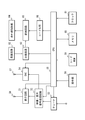
以下、図面を参照して本発明の実施の形態について説明する。図1は、本実施の形態にかかる音声処理装置の構成を示すブロック図である。音声処理装置1は、DSP(Digital Signal Processor)10と、DAC(Digital/Analog Converter)20と、を備える。DSP10は、音声データデコード部110と、制御部120と、重畳処理部130と、出力部140と、を備える。DAC20は、入力部210と、分離処理部220と、PCMデータ制御部230と、D/A変換部240と、を備える。本例では、出力部140と、入力部210と、の間は、3線式のシリアル通信により送受信を行う。
以下、図面を参照して本発明の実施の形態について説明する。図1は、本実施の形態にかかる音声処理装置の構成を示すブロック図である。音声処理装置1は、DSP(Digital Signal Processor)10と、DAC(Digital/Analog Converter)20と、を備える。DSP10は、音声データデコード部110と、制御部120と、重畳処理部130と、出力部140と、を備える。DAC20は、入力部210と、分離処理部220と、PCMデータ制御部230と、D/A変換部240と、を備える。本例では、出力部140と、入力部210と、の間は、3線式のシリアル通信により送受信を行う。
音声データデコード部110には、音声データである符号化ストリームが入力される。音声データデコード部110は、制御部120から入力されるデコード制御情報を用いて符号化ストリームをデコードし、デコード結果であるPCMデータを重畳処理部130に供給する。
制御部120は、音声データデコード部110に対してデコードに用いるデコード制御情報を供給する。さらに制御部120は、PCMデータに対する制御情報(以下、PCM制御情報と記載する。)を重畳処理部130に供給する。
重畳処理部130は、入力されたPCMデータとPCM制御情報とを、重畳したデータ(以下、重畳形式データとする。)を生成する。詳細には、重畳処理部130は、3線式のシリアル通信の信号における未使用領域にPCM制御情報を埋め込むことにより、重畳形式データを生成する。重畳処理部130は、生成した重畳形式データを出力部140に供給する。重畳形式データの詳細や生成方法は、図4~図6を参照して後述する。
出力部140は、DAC20内の入力部210に対して3線式のシリアルインターフェイスを介して重畳形式データを送信する処理部である。
入力部210には、3線式のシリアルインターフェイスを介して、PCMデータとPCM制御情報が重畳された重畳形式データが入力される。入力部210は、入力された重畳形式データを分離処理部220に供給する。
分離処理部220は、重畳形式データからPCMデータと、PCM制御情報と、を分離する。分離処理部220は、分離したPCMデータをPCM制御部230に供給する。さらに、分離処理部220は、分離したPCM制御情報を制御情報レジスタ231に書き込む。
PCMデータ制御部230は、制御情報レジスタ231の設定に従って、供給されたPCMデータに対して処理を行う。制御情報レジスタ231は、一般に複数のレジスタを有し、DAC20の設定に応じて必要なレジスタを読み出して処理を行う。PCMデータ制御部230は、当該処理後のPCMデータをD/A変換部240に供給する。
D/A変換部240は、供給されたPCMデータを、はしご形抵抗方式等の一般に用いられる方式に基づいて、Lチャネル用の音声アナログ信号またはRチャネル用の音声アナログ信号に変換する。D/A変換部240は、変換した音声アナログ信号を任意の処理部に供給する。
次に、図2を参照して重畳処理部130の動作を説明する。図2は、重畳処理部130の動作を示すフローチャートである。重畳処理部130には、音声データデコード部110からPCMデータが供給される(S11)。重畳処理部130は、制御部120からPCM制御情報が入力されているか否かを判定する(S12)。
PCM制御情報が入力されていないと判定した場合(S12:No)、重畳処理部130は、PCM制御情報を無効に設定する(S13)。重畳処理部130は、無効化したPCM制御情報とPCMデータを重畳した重畳形式データを生成する(S14)。
一方、PCM制御情報が入力されていると判定した場合(S12:Yes)、重畳処理部130は、PCMデータとPCM制御情報を重畳した重畳形式データを生成する(S15)。
重畳処理部130は、重畳形式データを出力部140に供給する(S16)。
次に、出力部140と、入力部210と、の間で送受信される通信データについて図3を参照して説明する。図示するように、32ビットのLチャネル用のデータと、32ビットのRチャネル用のデータが交互に送信される。Lチャネル用のデータと、Rチャネル用のデータは、同一タイミングの音声データである。本発明では、このLチャネル用のデータと、Rチャネル用のデータを、共に単位データと呼称する。また、単位データを構成するLチャネル用のデータをLチャネル単位データ、Rチャネル用のデータをRチャネル単位データと呼称する。
図12と同様に、Lチャネル単位データ及びRチャネル単位データには、16~24ビットのPCMデータがMSB(Most Significant Bit)側から格納される。さらに、Lチャネル単位データ及びRチャネル単位データには、8ビットのPCM制御情報がLSB(Least Significant Bit)側から格納される。このように、PCMデータとPCM制御情報を重畳した重畳形式データは、前述の重畳処理部130により生成される。
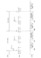
図4及び図5は、Lチャネル単位データ及びRチャネル単位データの詳細を示す概念図である。図4に示すように、PCM制御情報は、本例では8ビットの情報から構成される。また、図5に示すように、Lチャネル単位データに複数(図5の例では2つ)のPCM制御情報を挿入することや、Lチャネル単位データ及びRチャネル単位データの双方にPCM制御情報を挿入することも可能である。
続いて、PCM制御情報の詳細を図6に示す。PCM制御情報は、有効/無効を示す1ビット(EN)、制御情報レジスタ231のインデックスを示す3ビット(IDX0~IDX2)、及び制御情報レジスタ231への設定値を示す4ビット(Bit0~Bit3)、から構成される。
有効/無効を示す1ビット(EN)には、0または1が設定される。0が設定されている場合、当該PCM制御情報が無効であることを示す。一方、1が設定されている場合、当該PCM制御情報が有効であることを示す。
制御情報レジスタ231のインデックス(IDX0~IDX2)は、制御情報レジスタ231内のどのレジスタに対する設定であるかを示す情報である。図6では、制御情報レジスタ231は、Reg0~Reg7という8つの設定レジスタを備える。
制御情報レジスタ231への設定値(Bit0~Bit3)は、音声処理にかかる各種の設定である。なお、各設定値は、全て4ビットの情報である必要はない。例えば図6に示すように、無音設定(Mute)は、1ビットの情報である。この場合、設定に使用されない各ビットには、未使用領域を示す情報(Rsv)が挿入される。
なお、図6は、あくまでPCM制御情報の一例であり、制御情報レジスタ231のインデックスのサイズや制御情報レジスタ231への設定値のサイズは適宜変更することが可能である。
続いて、図7を参照して分離処理部220の動作を説明する。図7は、分離処理部220の動作を示すフローチャートである。分離処理部220には、入力部210から重畳形式データが入力される。分離処理部220は、重畳形式データをPCMデータと、PCM制御情報に分離する(S21)。分離処理部220は、Lチャネル単位データまたはRチャネル単位データのMSB側から16~24ビットを抽出することにより、PCMデータを取得する。さらに、分離処理部220は、Lチャネル単位データまたはRチャネル単位データのLSB側から8ビットを抽出することによりPCM制御情報を取得する。
続いて、分離処理部220は、抽出す他PCM制御情報が有効であるか否かを判定する(S22)。分離処理部220は、PCM制御情報内にある有効/無効を示すビットの値により、有効/無効を判定する。
PCM制御情報が有効である場合(S22:Yes)、分離処理部220は、PCM制御情報を制御情報レジスタ231に書き込む(S23)。書き込みの後、分離処理部220は、PCMデータをD/A変換部240に供給する(S24)。
一方、PCM制御情報が無効である場合(S22:No)、分離処理部220は、制御情報レジスタ231へのデータ書き込みを行わず、PCMデータをD/A変換部240に供給する(S24)。
続いて、本実施の形態にかかる音声処理装置の効果について説明する。本実施の形態にかかる音声処理装置では、空き領域に対してPCM制御情報を挿入することにより重畳形式データを生成し、当該重畳形式データをDSP10とDAC20間で送受信している。空き領域にPCM制御情報を挿入するため、PCMデータのデータ欠落が生じない。また、PCMデータとPCM制御情報を重畳した重畳形式データを送受信しているため、送受信に用いる入出力端子数が削減でき、装置の小型化が実現できる。
なお、重畳処理部130及び分離処理部220の処理は、CPUにより動作するプログラムとして実現することができる。このため、当該処理部により装置規模の増大を招くことはない。
上述のように、重畳処理部130は、各チャネル用単位データのLSB側から順にPCM制御情報を挿入している。これにより、分離処理部220は、各チャネル用単位データから固定長(上述の例では8ビット)を取得して有効性判断等を機械的に行うことができる。すなわち、PCM制御情報が挿入されている箇所が機械的処理に適した位置であるため、分離処理部220は、適切かつ高速にPCM制御情報を処理することができる。
さらに、重畳処理部130は、PCM制御情報に有効/無効を示す情報を挿入している。これにより、分離処理部220は、PCM制御情報が挿入されていないにもかかわらず、PCM制御情報を制御レジスタ231に書き込む等の誤操作を行う恐れがなくなる。
また、図5に示すように単位データ内に複数のPCM制御情報を包含することも可能である。これにより、音声処理に関する設定を頻繁に変更する必要がある場合であっても、分離処理部220は、制御情報レジスタ231を高い頻度で書き換えることができる。
<実施の形態2>
実施の形態2にかかる音声処理装置1は、PCM制御情報を分割し、複数の単位データに対して分割したPCM制御情報を挿入することを特徴とする。本実施の形態にかかる音声処理装置について、実施の形態1と異なる点を説明する。
実施の形態2にかかる音声処理装置1は、PCM制御情報を分割し、複数の単位データに対して分割したPCM制御情報を挿入することを特徴とする。本実施の形態にかかる音声処理装置について、実施の形態1と異なる点を説明する。
実施の形態2にかかる音声処理装置の構成は、図1に示す構成と同じである。重畳処理部130は、単位データの空き領域よりも大きなサイズのPCM制御情報を分割し、分割したPCM制御情報を複数の単位データの空き領域に挿入する。図8は、本実施の形態にかかる重畳形式データを示す概念図である。本例では、24ビットのPCM制御情報を対象とする。
重畳処理部130は、制御部120から供給されたPCM制御情報を3分割する。そして、重畳処理部130は、ある単位データ内のLチャネル単位データ及びRチャネル単位データのLSB側から分割したPCM制御情報を挿入する。さらに、重畳処理部130は、この単位データに後続する単位データ内のLチャネル単位データのLSB側から分割したPCM制御情報を挿入する。そして、重畳処理部130は、重畳形式データを出力部140に供給する。DSP10内での他の処理は、実施の形態1と同様である。
分離処理部220は、Lチャネル単位データ及びRチャネル単位データのLSB側から8ビットを抽出し、それぞれに有効を示すビットが設定されている場合、当該Lチャネル単位データのLSB側から8ビットが分割されたPCM制御情報の先頭データと判定する。そして、分離処理部220は、当該単位データに後続するLチャネル単位データから8ビットを抽出する。そして、分離処理部220は、3つの分割されたPCM制御情報(8ビット)をつなぎ合わせることにより、PCM制御情報を復元する。DAC20内での他の処理は、実施の形態1と同様である。
上述のように、本実施の形態にかかる音声処理装置は、単位データをまたぐ大きなサイズのPCM制御情報を扱うことができる。これにより、例えばレジスタへの設定が複雑なためデータサイズが大きいPCM制御情報、制御情報レジスタ231内のレジスタ数が多いためにデータサイズが大きいPCM制御情報、等を扱うことが可能となる。
なお、上述の説明では、PCM制御情報を3つに分割したが、分割数は任意の数でよい。また、重畳処理部130は、分割したPCM制御情報に対して分割にかかるPCM制御情報であるか否かを示す情報を挿入し、分離処理部220は、当該情報を用いて分割したPCM制御情報を復元しても良い。
<実施の形態3>
本実施の形態にかかる音声処理装置1は、異なるデータサイズのPCM制御情報を扱うことを特徴とする。本実施の形態にかかる音声処理装置1について実施の形態1と異なる点を説明する。
本実施の形態にかかる音声処理装置1は、異なるデータサイズのPCM制御情報を扱うことを特徴とする。本実施の形態にかかる音声処理装置1について実施の形態1と異なる点を説明する。
図9は、本実施の形態にかかるPCM制御情報を示す図である。図示するように、PCM制御情報は、LSB側から制御情報レジスタインデックス(IDX0~IDX2)、有効/無効情報(EN)、制御情報レジスタ231への設定値(Bit0~Bit3)の順序で情報が整列される。
ここで、制御情報レジスタインデックスの値に応じて、制御情報レジスタ231への設定値のデータサイズが異なる。例えば、Reg0への設定値は、1ビットの情報である。Reg1への設定値は、2ビットの情報である。
重畳処理部130は、Lチャネル単位データまたはRチャネル単位データのLSB側からPCM制御情報を順に挿入する。図10に挿入例を示す。本例では、Lチャネル単位データ及びRチャネル単位データに含まれるPCMデータは、16ビットのデータサイズである。重畳処理部130は、図示するように、空き領域に対して異なるデータサイズのPCM制御情報をLSB側から順に挿入する。
分離処理部220は、Lチャネル単位データまたはRチャネル単位データのLSB側から情報を読み出す。ここで、分離処理部220は、読み出した制御情報レジスタインデックス(IDX0~IDX2)に応じて、PCM制御情報のデータサイズを把握する。例えば、制御情報レジスタインデックスが"000"である場合、分離処理部220は、PCM制御情報のデータサイズは5ビットであると判定する。分離処理部220は、あるPCM制御情報を読み出して解析した後に、次のPCM制御情報を同一のL(R)チャネル単位データから読み出す。
上述したように、PCM制御情報には、情報を持たない予約領域が含まれない。すなわち、PCM制御情報のデータサイズが小さく抑えられる。そのため、重畳処理部130は、一つの単位データに対して多くのPCM制御情報を挿入できる可能性が高くなる。これにより、例えば制御情報レジスタ231の値を頻繁に変更して音声制御を行う必要がある場合に対しても適切に対応することができる。
なお、本発明は上記実施の形態に限られたものではなく、趣旨を逸脱しない範囲で適宜変更することが可能である。例えば、DSP10の後段に位置する装置としてDAC20を備える構成を説明したが、必ずしもこれに限られず、DSP10の後段に出力アンプ等を配置しても良い。すなわち、本発明は、DSP10のように重畳形式データを生成する第1の装置と、DAC20のように重畳形式データからPCMデータとPCM制御情報を復元する第2の装置を備える様々なシステムに応用可能である。
なお、上述のDSP10とDAC20との間で送受信されるデータは、例えばオシロスコープ等の機器を用いることにより確認することができる。すなわち、DSP10とDAC20との間で送受信されるデータをダンプすることにより、本発明にかかる通信(重畳形式データによるデータ通信)を行っているか否かを確認することができる。
上記したように、重畳処理部130及び分離処理部220の処理は、任意のコンピュータ内で動作するプログラムとして実現することが可能である。プログラムは、様々なタイプの非一時的なコンピュータ可読媒体(non-transitory computer readable medium)を用いて格納され、コンピュータに供給することができる。非一時的なコンピュータ可読媒体は、様々なタイプの実体のある記録媒体(tangible storage medium)を含む。非一時的なコンピュータ可読媒体の例は、磁気記録媒体(例えばフレキシブルディスク、磁気テープ、ハードディスクドライブ)、光磁気記録媒体(例えば光磁気ディスク)、CD-ROM(Read Only Memory)、CD-R、CD-R/W、半導体メモリ(例えば、マスクROM、PROM(Programmable ROM)、EPROM(Erasable PROM)、フラッシュROM、RAM(random access memory))を含む。また、プログラムは、様々なタイプの一時的なコンピュータ可読媒体(transitory computer readable medium)によってコンピュータに供給されてもよい。一時的なコンピュータ可読媒体の例は、電気信号、光信号、及び電磁波を含む。一時的なコンピュータ可読媒体は、電線及び光ファイバ等の有線通信路、又は無線通信路を介して、プログラムをコンピュータに供給できる。
この出願は、2011年4月6日に出願された日本出願特願2011-084411を基礎とする優先権を主張し、その開示の全てをここに取り込む。
1 音声処理装置
10 DSP(デジタルシグナルプロセッサ)
110 音声データデコード部
120 制御部
130 重畳処理部
140 出力部
20 DAコンバータ
210 入力部
220 分離処理部
230 PCMデータ制御部
231 制御情報レジスタ
240 D/A変換部
10 DSP(デジタルシグナルプロセッサ)
110 音声データデコード部
120 制御部
130 重畳処理部
140 出力部
20 DAコンバータ
210 入力部
220 分離処理部
230 PCMデータ制御部
231 制御情報レジスタ
240 D/A変換部
Claims (15)
- 符号化ストリームをデコードしたパルス符号変調データを含む単位データの空き領域に、前記パルス符号変調データの制御情報を挿入した重畳形式データを生成して出力する第1装置と、
前記重畳形式データを前記パルス符号変調データと、前記制御情報と、に分離し、前記パルス符号変調データに対し、前記制御情報に基づいて制御処理を実行する第2装置と、を備える音声処理装置。 - 前記第1装置は、前記単位データに含まれるチャネルのMSB(Most Significant Bit)側から前記パルス符号変調データを配置し、前記単位データに含まれるチャネルのLSB(Least Significant Bit)側から前記制御情報を挿入することにより前記重畳形式データを生成することを特徴とする請求項1に記載の音声処理装置。
- 前記制御情報は、当該制御情報の有効性を示す情報を含み、
前記第2装置は、当該有効性に基づいて前記制御処理を実行することを特徴とする請求項1または請求項2に記載の音声処理装置。 - 前記第1装置は、前記単位データに対して複数の前記制御情報を挿入して前記重畳形式データを生成し、
前記第2装置は、前記重畳形式データから複数の前記制御情報を取得することを特徴とする請求項1乃至請求項3のいずれか1項に記載の音声処理措置。 - 前記第1装置は、前記制御情報を分割した分割制御情報を挿入することにより前記重畳形式データを生成し、
前記第2装置は、前記重畳形式データから前記分割制御情報を取得し、複数の前記分割制御情報から前記制御情報を復元することを特徴とする請求項1乃至請求項3のいずれか1項に記載の音声処理措置。 - 前記制御情報は、前記有効性を示す情報と、制御内容にかかる制御内容情報と、前記第2装置における前記制御内容情報の書き込み先と、にかかる情報を含み、
前記制御内容情報のデータサイズは、前記制御内容に応じて定まることを特徴とする請求項1乃至請求項4のいずれか1項に記載の音声処理措置。 - 前記第1装置は、DSP(デジタルシグナルプロセッサ)であり、
前記第2装置は、前記パルス符号変調データを前記制御情報に基づいて制御した後にアナログ信号に変換するDA(デジタル/アナログ)コンバータであることを特徴とする請求項1乃至請求項6のいずれか1項に記載の音声処理装置。 - 第1装置と第2装置との間で符号ストリームにかかる情報を送受信する音声データ処理方法であって、
前記第1装置は、前記符号化ストリームをデコードしたパルス符号変調データを含む単位データの空き領域に、前記パルス符号変調データの制御情報を挿入した重畳形式データを生成して出力し、
前記第2装置は、前記重畳形式データを前記パルス符号変調データと、前記制御情報と、に分離し、前記パルス符号変調データに対し、前記制御情報に基づいて制御処理を実行する、音声データ処理方法。 - 前記第1装置は、前記単位データに含まれるチャネルのMSB側から前記パルス符号変調データを配置し、前記単位データに含まれるチャネルのLSB側から前記制御情報を挿入することにより前記重畳形式データを生成することを特徴とする音声データ処理方法。
- 前記制御情報は、当該制御情報の有効性を示す情報を含み、
前記第2装置は、当該有効性に基づいて前記制御処理を実行することを特徴とする請求項8または請求項9に記載の音声データ処理方法。 - 前記第1装置は、前記単位データに対して複数の前記制御情報を挿入して前記重畳形式データを生成し、
前記第2装置は、前記重畳形式データから複数の前記制御情報を取得することを特徴とする請求項8乃至請求項10のいずれか1項に記載の音声データ処理方法。 - 前記第1装置は、前記制御情報を分割した分割制御情報を挿入することにより前記重畳形式データを生成し、
前記第2装置は、前記重畳形式データから前記分割制御情報を取得し、複数の前記分割制御情報から前記制御情報を復元することを特徴とする請求項8乃至請求項10のいずれか1項に記載の音声データ処理方法。 - 前記制御情報は、前記有効性を示す情報と、制御内容にかかる制御内容情報と、前記第2装置における前記制御内容情報の書き込み先と、にかかる情報を含み、
前記制御内容情報のデータサイズは、前記制御内容に応じて定まることを特徴とする請求項8乃至請求項12のいずれか1項に記載の音声データ処理方法。 - 前記第1装置は、DSP(デジタルシグナルプロセッサ)であり、
前記第2装置は、前記パルス符号変調データを前記制御情報に基づいて制御した後にアナログ信号に変換するDA(デジタル/アナログ)コンバータであることを特徴とする請求項8乃至請求項13のいずれか1項に記載の音声データ処理方法。 - 符号化ストリームを送信するためのデータを生成する生成処理をするためのプログラムであって、
前記生成処理は、前記符号化ストリームをデコードしたパルス符号変調データを含む単位データの空き領域に、前記パルス符号変調データの制御情報を挿入した重畳形式データを生成する、音声データ処理プログラム。
Applications Claiming Priority (2)
| Application Number | Priority Date | Filing Date | Title |
|---|---|---|---|
| JP2011-084411 | 2011-04-06 | ||
| JP2011084411 | 2011-04-06 |
Publications (1)
| Publication Number | Publication Date |
|---|---|
| WO2012137455A1 true WO2012137455A1 (ja) | 2012-10-11 |
Family
ID=46968866
Family Applications (1)
| Application Number | Title | Priority Date | Filing Date |
|---|---|---|---|
| PCT/JP2012/002245 Ceased WO2012137455A1 (ja) | 2011-04-06 | 2012-03-30 | 音声処理装置、音声データ処理方法、音声データ処理プログラム |
Country Status (1)
| Country | Link |
|---|---|
| WO (1) | WO2012137455A1 (ja) |
Citations (4)
| Publication number | Priority date | Publication date | Assignee | Title |
|---|---|---|---|---|
| JP2005150860A (ja) * | 2003-11-11 | 2005-06-09 | Matsushita Electric Ind Co Ltd | データ送信装置及びデータ受信装置 |
| JP2007019910A (ja) * | 2005-07-08 | 2007-01-25 | Alpine Electronics Inc | 信号処理装置及び信号処理方法 |
| JP2007299450A (ja) * | 2006-04-28 | 2007-11-15 | Kenwood Corp | オーディオ処理装置及び方法 |
| JP2008016094A (ja) * | 2006-07-04 | 2008-01-24 | Fujitsu Ten Ltd | データ転送制御装置及びデータ再生記録装置 |
-
2012
- 2012-03-30 WO PCT/JP2012/002245 patent/WO2012137455A1/ja not_active Ceased
Patent Citations (4)
| Publication number | Priority date | Publication date | Assignee | Title |
|---|---|---|---|---|
| JP2005150860A (ja) * | 2003-11-11 | 2005-06-09 | Matsushita Electric Ind Co Ltd | データ送信装置及びデータ受信装置 |
| JP2007019910A (ja) * | 2005-07-08 | 2007-01-25 | Alpine Electronics Inc | 信号処理装置及び信号処理方法 |
| JP2007299450A (ja) * | 2006-04-28 | 2007-11-15 | Kenwood Corp | オーディオ処理装置及び方法 |
| JP2008016094A (ja) * | 2006-07-04 | 2008-01-24 | Fujitsu Ten Ltd | データ転送制御装置及びデータ再生記録装置 |
Similar Documents
| Publication | Publication Date | Title |
|---|---|---|
| JP5118022B2 (ja) | オーディオ信号の符号化/復号化方法及び符号化/復号化装置 | |
| UA128634C2 (uk) | Способи і пристрої для формування або декодування бітового потоку, який містить імерсивні аудіосигнали | |
| CN115206352B (zh) | 音频处理方法、装置、芯片、电子设备及存储介质 | |
| WO2007116809A1 (ja) | ステレオ音声符号化装置、ステレオ音声復号装置、およびこれらの方法 | |
| CN115273869B (zh) | 音频数据传输方法、装置、芯片、电子设备及存储介质 | |
| CN1123885C (zh) | 用于从一种记录载体中再现数字音频信号的装置和方法 | |
| JP2008503793A (ja) | 残響サウンド信号のコーディング | |
| US11050971B2 (en) | Pulse code modulation (PCM) data-marking | |
| CN105869647B (zh) | 一种智能手机原生dsd音频解码方法、系统及智能手机 | |
| TW382861B (en) | Digital data encoding apparatus and method thereof | |
| CN117278775A (zh) | 传输音频数据的方法、装置、电子设备及音频播放设备 | |
| CN110838298A (zh) | 多声道音频数据的处理方法、装置、设备和存储介质 | |
| KR100682915B1 (ko) | 다채널 신호 부호화/복호화 방법 및 장치 | |
| CN115132213B (zh) | 音频数据传输方法、装置、芯片、电子设备及存储介质 | |
| JP2009033649A (ja) | コンテンツデータ送受信システム、コンテンツデータ送信装置、コンテンツデータ受信装置、コンテンツデータ送信方法、コンテンツデータ受信処理方法 | |
| KR20060122694A (ko) | 두 채널 이상의 다운믹스 오디오 신호에 공간 정보비트스트림을 삽입하는 방법 | |
| CN102760438A (zh) | 混音方法与混音装置 | |
| JP4815780B2 (ja) | オーバーサンプリングシステム、デコードlsi、およびオーバーサンプリング方法 | |
| JP2008108100A (ja) | 音声データ処理装置 | |
| CN112216310A (zh) | 音频处理方法与装置、以及多声道系统 | |
| KR100826942B1 (ko) | 디지털 오디오 데이터의 비트 변환 방법, 이를 수행하는디코더 장치 및 디지털 오디오 데이터의 재생 방법 | |
| CN118351861A (zh) | 通信方法和系统、音频设备及芯片 | |
| WO2007035043A1 (en) | Apparatus and method for playing audio using dma | |
| CN118351860A (zh) | 通信方法和系统、音频设备及芯片 | |
| CN115240692A (zh) | 接收音频数据的方法、装置以及音频播放设备 |
Legal Events
| Date | Code | Title | Description |
|---|---|---|---|
| 121 | Ep: the epo has been informed by wipo that ep was designated in this application |
Ref document number: 12767335 Country of ref document: EP Kind code of ref document: A1 |
|
| NENP | Non-entry into the national phase |
Ref country code: DE |
|
| 122 | Ep: pct application non-entry in european phase |
Ref document number: 12767335 Country of ref document: EP Kind code of ref document: A1 |
|
| NENP | Non-entry into the national phase |
Ref country code: JP |