WO2012133628A1 - フィールド機器 - Google Patents
フィールド機器 Download PDFInfo
- Publication number
- WO2012133628A1 WO2012133628A1 PCT/JP2012/058328 JP2012058328W WO2012133628A1 WO 2012133628 A1 WO2012133628 A1 WO 2012133628A1 JP 2012058328 W JP2012058328 W JP 2012058328W WO 2012133628 A1 WO2012133628 A1 WO 2012133628A1
- Authority
- WO
- WIPO (PCT)
- Prior art keywords
- battery
- mounting direction
- case
- attachment
- field device
- Prior art date
- Legal status (The legal status is an assumption and is not a legal conclusion. Google has not performed a legal analysis and makes no representation as to the accuracy of the status listed.)
- Ceased
Links
Images












Classifications
-
- G—PHYSICS
- G01—MEASURING; TESTING
- G01D—MEASURING NOT SPECIALLY ADAPTED FOR A SPECIFIC VARIABLE; ARRANGEMENTS FOR MEASURING TWO OR MORE VARIABLES NOT COVERED IN A SINGLE OTHER SUBCLASS; TARIFF METERING APPARATUS; MEASURING OR TESTING NOT OTHERWISE PROVIDED FOR
- G01D11/00—Component parts of measuring arrangements not specially adapted for a specific variable
- G01D11/24—Housings ; Casings for instruments
-
- G—PHYSICS
- G05—CONTROLLING; REGULATING
- G05B—CONTROL OR REGULATING SYSTEMS IN GENERAL; FUNCTIONAL ELEMENTS OF SUCH SYSTEMS; MONITORING OR TESTING ARRANGEMENTS FOR SUCH SYSTEMS OR ELEMENTS
- G05B2219/00—Program-control systems
- G05B2219/20—Pc systems
- G05B2219/25—Pc structure of the system
- G05B2219/25428—Field device
Definitions
- the present invention relates to a field device that is attached to equipment such as a plant and operates with a built-in battery.
- field devices that measure physical quantities and communicate data to notify measured values are used as field devices that measure physical quantities such as pressure, flow rate, temperature, etc., by operating circuits with built-in batteries. There are cases (see, for example, Patent Document 1).
- the plant manager performs replacement at a cycle shorter than the lifetime, or determines the appropriate time for each while checking the individual battery lifetime. It will be. In the former case, even a battery that has not reached the end of its life and does not require replacement is replaced. On the other hand, in the latter case, it takes time to confirm the battery life of each individual battery. Therefore, in any case, there has been a problem that the number of times of maintenance and the work load increase.
- the present invention is intended to solve such a problem, and an object of the present invention is to provide a field device that can reduce a work load required for maintenance of a built-in battery.
- a field device stores a battery, is inserted into the device case from the opening, and is attached to the inside of the device case, and the device A mounting portion provided inside the case for mounting the battery case in such a manner that the mounting direction of the battery case can be changed according to the installation direction of the device case so that the battery has a predetermined normal mounting direction. ing.
- the mounting direction of the battery case can be changed in accordance with the installation direction of the device case so that the battery is in a normal mounting direction in which the battery is oriented in a certain direction with respect to the vertical direction.
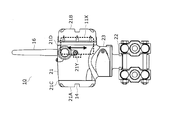
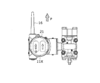
- FIG. 1A is a front view showing the configuration of the field device according to the first embodiment.
- FIG. 1B is a side view showing the configuration of the field device according to the first embodiment.
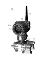
- FIG. 2 is an external view of the field device according to the first embodiment.
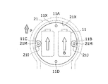
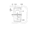
- FIG. 3A is a front cross-sectional view showing a battery mounting main part of the field device according to the first embodiment.
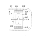
- FIG. 3B is a side cross-sectional view showing the battery attachment main part of the field device according to the first embodiment.
- FIG. 4A is an explanatory diagram showing a battery mounting direction (when a field device is installed in an upright state).
- FIG. 4B is an explanatory diagram showing a battery mounting direction (when the field device is installed in a sideways state).
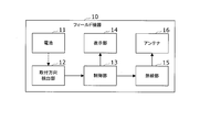
- FIG. 5 is a functional block diagram of a field device according to the second embodiment.
- FIG. 6A is a front sectional view showing attachment of the acceleration sensor.
- FIG. 6B is a side sectional view showing attachment of the acceleration sensor.
- FIG. 7 is a flowchart showing battery attachment direction determination processing according to the second embodiment.
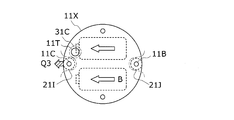
- FIG. 8A is a front cross-sectional view showing a battery mounting direction detection principal part of the field device according to the second embodiment.
- FIG. 8B is a side cross-sectional view illustrating the battery attachment direction detection essential part of the field device according to the second embodiment.
- FIG. 9A is an explanatory diagram showing a relative attachment direction Q1 with respect to the device case.
- FIG. 9B is an explanatory diagram showing a relative attachment direction Q2 with respect to the device case.
- FIG. 9C is an explanatory diagram showing a relative attachment direction Q3 with respect to the device case.
- FIG. 9D is an explanatory diagram showing a relative attachment direction Q4 with respect to the device case.
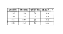
- FIG. 10 is an explanatory diagram showing the correspondence between the battery mounting direction and the operation detection switch.
- FIG. 11 is a front view showing a field device according to the fourth embodiment.
- FIG. 12 is an explanatory diagram showing the correspondence between the antenna mounting direction and the battery mounting direction.
- FIG. 13 is a flowchart showing battery attachment direction determination processing according to the fourth embodiment.
- FIG. 14A is a front cross-sectional view illustrating a display unit mounting direction detection principal part of a field device according to a fifth embodiment.
- FIG. 14B is a side cross-sectional view illustrating the display unit mounting direction detection essential part of the field device according to the fifth embodiment.
- FIG. 15A is an explanatory diagram showing a relative mounting direction R1 with respect to the device case.
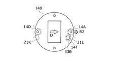
- FIG. 15B is an explanatory diagram showing a relative attachment direction R2 with respect to the device case.
- FIG. 15C is an explanatory diagram illustrating a relative attachment direction R3 with respect to the device case.
- FIG. 15D is an explanatory diagram showing a relative attachment direction R4 with respect to the device case.
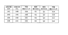
- FIG. 16 is an explanatory diagram illustrating a correspondence relationship between the display unit mounting direction and the operation detection switch.
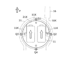
- FIG. 17A is a front cross-sectional view showing the battery and antenna mounting principal parts of the field device according to the sixth embodiment.
- FIG. 17A is a front cross-sectional view showing the battery and antenna mounting principal parts of the field device according to the sixth embodiment.
- FIG. 17B is a side cross-sectional view showing the battery and antenna attachment main parts of the field device according to the sixth embodiment.
- FIG. 18A is an explanatory diagram showing a battery mounting direction (when the field device is installed in an upright state).
- FIG. 18B is an explanatory diagram showing a battery mounting direction (when the field device is installed in a sideways state).
- Battery life is greatly affected by its installation orientation.
- the installation posture vertical and horizontal directions of the field device itself at the time of attachment
- the direction of the battery is determined depending on the vertical and horizontal directions of the field device itself. And since the battery life fluctuated depending on the direction, the inventor noticed that this becomes an uncertain element of the battery life.
- the uncertain factors can be reduced by adopting a structure in which the direction in which the battery is built into the field device itself can be selected and changed even after the field device itself is attached to the plant.
- the battery since there is an environment that is susceptible to vibration such as a compressor in a plant, it is desirable that the battery can be securely fixed even in a structure that can selectively change the mounting direction of the battery. For example, it is preferable to provide a reliable mounting structure at a low cost by minimizing the direction in which the selection can be changed to 90 ° (corresponding to vertical and horizontal directions).
- the field device 10 is a field device that is used in facilities such as a plant and measures physical quantities such as pressure, flow rate, and temperature.
- the field device 10 includes a device case 21, a front cover 21A, a back cover 21B, a detection unit 22, and a connection unit 23.
- the device case 21 is formed of a cylindrical or box-shaped metal housing in which various electronic circuits are incorporated.
- a front cover 21A is attached to one opening 21C, and a back cover 21B is attached to the other opening 21D.
- a detection unit 22 is connected via a connecting unit 23, and a physical quantity related to an object such as a fluid or a gas guided to the detection unit 22 is incorporated in the detection unit 22. Is detected.
- a battery case 11X containing the battery 11 is attached inside the opening 21D side of the device case 21, and a display panel 14X containing the display unit 14 is attached inside the opening 21C side of the device case 21. ing.
- an antenna 16 for wireless communication is fixed to the outer surface of the device case 21.
- FIGS. 3A and 3B two batteries 11 are accommodated in the battery case 11X with the electrode directions aligned.
- a plurality of holes 11A, 11B, 11C, and 11D are formed on the same circumference in the periphery of the battery case 11X.
- attachment portions 21I and 21J for attaching the battery case 11X to the inner wall 21X of the device case 21 are provided.
- the mounting portions 21I and 21J are formed by projecting part of the inner wall 21X facing each other, and a screw 21M penetrating the holes 11A, 11B, 11C and 11D of the battery case 11X is attached to the mounting portions 21I and 21J.
- the battery case 11X is screwed to the inner wall 21X by being screwed into the screw holes formed in.
- the attachment portions 21I and 21J are provided opposite to each other in the left-right direction of the inner wall 21X, and the battery case 11X has four holes 11A, 11B, 11C, and 11D corresponding to the inner wall 21X orthogonal to each other. It is provided at an angle. Accordingly, by selecting two holes to be screwed to the attachment portions 21I and 21J from the holes 11A, 11B, 11C, and 11D, the battery case 11X is rotated, so that any of the four attachment directions can be selected. It can be attached to the inside of the device case 21 in the mounting direction.
- the battery mounting direction B of the battery 11 can be mounted along the regular mounting direction P by screwing the hole 11A to the mounting portion 21I and screwing the hole 11B to the mounting portion 21J.
- the case where the direction of the positive electrode 11P from the center position of the battery 11 is defined as the battery mounting direction B and the upper vertical direction is defined as the normal mounting direction P will be described as an example.
- the attachment direction in which the lifetime of the battery 11 becomes the longest is determined by factors such as the shape and internal structure of the battery 11, it may be determined in advance according to the type of the battery to be used.
- the battery attachment direction B is directed to the left side and is different from the normal attachment direction P.
- the battery attachment direction B of the battery 11 can be attached along the normal attachment direction P by screwing the hole 11D to the attachment portion 21I and screwing the hole 11C to the attachment portion 21J.
- the mounting direction of the battery case 11X can be changed according to the installation direction of the device case 21 so that the battery 11 is in the normal mounting direction P in which the battery 11 is oriented in a certain direction with respect to the vertical direction. Can be attached to.
- a hole may be formed in accordance with the installation direction of the field device 10. For example, when the field device 10 is installed in either the left or right sideways state, it is only necessary to provide only the holes 11A and 11D so that two types of left and right attachment methods can be selected. For example, when the field device 10 is installed in units of 45 °, eight holes may be formed in the battery case 11X every 45 °.
- any of the holes provided in the battery case 11X is selected for screwing. You may do it. Specifically, even when two holes are formed in the battery case 11X and four attachment portions are formed every 90 ° on the inner wall 21X of the device case 21, as in the configurations of FIGS. 3A and 3B, A type of mounting direction can be selected. Note that the number and angle of the holes of the battery case 11X and the attachment portions of the inner wall 21X of the device case 21 are not limited to these examples, and depend on the relationship between the installation direction of the field device 10 and the normal attachment direction. Then, each number and angle may be selected.
- an attachment direction detection unit 12 that detects the attachment direction of the battery 11 is provided, and an alarm is notified when the battery attachment direction is different from the normal attachment direction. The case will be described.
- the field device 10 is provided with an attachment direction detection unit 12, a control unit 13, a display unit 14, a radio unit 15, and an antenna 16 as electronic circuits.
- the attachment direction detection unit 12 has a function of detecting the attachment direction of the battery 11 (battery case 11X).
- an acceleration sensor 12S may be attached to the battery case 11X, and the battery attachment direction B with respect to the vertical direction may be detected based on the output from the acceleration sensor 12S.
- the control unit 13 includes a CPU and a dedicated control circuit.
- the control unit 13 acquires a detection result from a sensor (not shown) of the detection unit 22, a function of transmitting the detection result from the radio unit 15 by radio waves,
- the display unit 14 has a function of displaying the detection result.
- the control unit 13 confirms whether or not the battery mounting direction B detected by the mounting direction detection unit 12 is the normal mounting direction P, and the battery mounting direction B is different from the normal mounting direction P.
- the function of notifying the alarm by transmitting alarm information from the wireless unit 15 by radio waves, and the function of notifying the alarm by displaying the alarm on the display unit 14 when the battery mounting direction B is different from the normal mounting direction P And have.
- the display unit 14 includes a display device such as an LED or an LCD, and has a function of displaying various types of information such as detection results and alarms in accordance with instructions from the control unit 13.
- the wireless unit 15 includes a dedicated wireless communication circuit, and has a function of transmitting various information such as detection results and alarms from the antenna 16 by radio waves in accordance with instructions from the control unit 13.
- the remaining configuration of the field device 10 according to the present embodiment is the same as that of the first embodiment, and a detailed description thereof is omitted here.
- the control unit 13 detects the battery mounting direction B by controlling the mounting direction detection unit 12 (step 100) and compares it with a preset normal mounting direction P (step 101). At this time, when the battery mounting direction B is detected by the acceleration sensor, a triaxial angle is obtained as a detection result. Therefore, it is confirmed whether or not the battery mounting direction B is the normal mounting direction P by determining whether or not the detection result is included in a preset angle range indicating the normal mounting direction P. Can do.
- step 101: YES when the detection result is included in the preset angular range indicating the normal attachment direction P and the battery attachment direction B is the normal attachment direction P (step 101: YES), the control unit 13 A series of battery attachment direction determination processes are terminated without performing the alarm notification process.
- the control unit 13 performs the alarm notification process as follows: Alarm information is transmitted by radio waves from the wireless unit 15 (step 102), an alarm is displayed on the display unit 14 (step 103), and a series of battery attachment direction determination processing is completed.
- the field device 10 moves to a host device (not shown) such as a controller. Since the alarm information is automatically transmitted or the alarm is displayed on the display unit 14 of the field device 10, the worker can take appropriate measures.
- the angle range indicating the normal mounting direction P should be set in advance in consideration of the relationship between the angle range and the battery life variation degree, the relationship between the battery life variation degree and the actual maintenance cycle, and the like. That's fine.
- the case where the battery mounting direction of the battery 11 is detected using an acceleration sensor has been described as an example.
- a case will be described in which the battery mounting direction relative to the field device 10 is detected using a detection switch such as a mechanical switch or an optical switch.
- the attachment direction detection unit 12 has a function of detecting the relative attachment direction of the battery case 11X with respect to the device case 21 as the battery attachment direction. Further, the control unit 13 determines whether or not the battery mounting direction detected by the mounting direction detection unit 12 is a matching direction indicating the normal mounting direction P viewed from the field device 10, thereby determining the battery mounting direction B. Has a function of confirming whether or not is the normal mounting direction P.
- a protrusion 11T is provided on the surface of the battery case 11X on the side of the attachment portions 21I and 21J.
- a substrate (PCB) 31 is fixed inside the device case 21 so as to face the battery case 11X, and the four detection switches 31A, 31B, 31C constituting the mounting direction detection unit 12 are mounted on the substrate 31. , 31D are implemented. These detection switches 31A, 31B, 31C, and 31D are mounted at positions that operate in contact with the convex portion 11T when the battery case 11X is screwed to the mounting portions 21I and 21J, respectively.
- the relative mounting direction Q1 indicates the direction in which the battery mounting direction B is oriented in a state where the holes 11C and 11B are screwed to the mounting portions 21I and 21J.
- the relative mounting direction Q1 is detected by the convex portion 11T.
- the switch 31A is activated.
- the relative mounting direction Q2 indicates the direction in which the battery mounting direction B is oriented in the state where the holes 11D and 11A are screwed to the mounting portions 21I and 21J.
- the relative mounting direction Q2 is detected by the convex portion 11T.
- the switch 31B is activated.
- the relative attachment direction Q3 indicates the direction in which the battery attachment direction B is directed in a state where the holes 11A and 11D are screwed to the attachment portions 21I and 21J. In this case, the protrusion 11T Thus, the detection switch 31C is activated.
- the relative mounting direction Q4 indicates the direction in which the battery mounting direction B is oriented in a state where the holes 11B and 11C are screwed to the mounting portions 21I and 21J. In this case, the relative mounting direction Q4 is detected by the convex portion 11T. The switch 31D is activated.
- the field device 10 may be installed in a direction other than the upright state, but is often installed in a fixed direction such as an upright state. .
- the normal attachment direction P is fixedly determined with respect to the installation direction of the field device 10.
- the alignment direction indicating the normal mounting direction viewed from the field device 10 is the relative mounting direction Q1 in FIGS. 8A and 8B. . Therefore, if the battery case 11X is attached to the field device 10 in such a relative attachment direction Q1, whether or not there is an error in the attachment direction of the battery 11 can be confirmed by checking with the detection switch.
- the control unit 13 detects the battery mounting direction and the operation detection as shown in FIG. Based on the table showing the correspondence with the switch, it can be confirmed that the battery is oriented in the relative mounting direction Q1. Therefore, in this case, since the alignment direction when the field device 10 is installed in the upright state, that is, the relative mounting direction Q1, coincides, it is determined that the battery mounting direction is the normal mounting direction.
- the case where the relative battery mounting direction of the battery 11 with respect to the field device 10 is detected using the detection switch has been described as an example.
- a case will be described in which it is confirmed whether or not the battery mounting direction is the normal mounting direction by detecting the mounting direction of the antenna 16 and comparing it with the battery mounting direction.
- the antenna 16 is often erected upward in the vertical direction in order to keep the radio wave propagation state in a good state, and is not affected by the installation direction of the field device 10. For this reason, if the mounting direction of the antenna 16 is detected, the vertical direction can be specified, and as a result, the matching direction indicating the normal mounting direction P viewed from the field device 10 can be specified.
- the attachment direction detection unit 12 has a function of detecting the antenna attachment direction of the antenna attached to the device case 21.
- the control unit 13 has a function of confirming whether or not the battery mounting direction is the normal mounting direction by comparing the antenna mounting direction detected by the mounting direction detection unit 12 with the battery mounting direction.
- connection holes are provided on the outer surface of the device case 21 as a configuration for standing the antenna 16 vertically upward.
- detection switches 32A, 32B, and 32C constituting the attachment direction detection unit 12 are provided in these connection holes, and the presence / absence of attachment of the antenna 16 to each connection hole is detected. Therefore, in FIG. 11, when the field device 10 is installed in an upright state, the antenna 16A is connected to the device case 21, so that the detection switch 32A is activated. On the other hand, when the field device 10 is installed in the sideways state, the antenna switch 16B or the antenna switch 16C is connected to the device case 21, so that the detection switch 32B or the detection switch 32C is activated.
- the direction in which the antenna 16 is directed is the normal mounting direction P of the battery 11, as shown in FIG. 11, when the field device 10 to which the antenna 16A is connected is installed in an upright state,
- the attachment direction is P1
- the battery 11 may be attached to the field device 10 in the relative attachment direction Q1 in order to attach the battery 11 in the regular attachment direction P1.
- the normal mounting direction is P2
- the battery 11 is attached to the field device 10 in order to mount the battery 11 in the normal mounting direction P2.
- 11 can be attached in the relative attachment direction Q2.
- the normal attachment direction is P3, and in order to attach the battery 11 in the normal attachment direction P3, It can be seen that the battery 11 may be attached in the relative attachment direction Q3.
- the battery 11 when the connection of the antenna 16A is detected by the operation of the detection switch 32A, if the operation of the detection switch 31A is confirmed, the battery 11 is directed in the normal mounting direction P1. I can confirm that. Further, when the connection of the antenna 16B is detected by the operation of the detection switch 32B, if the operation of the detection switch 31B is confirmed, the battery 11 can be confirmed to be oriented in the normal mounting direction P2. When the connection of the antenna 16C is detected by the operation of the detection switch 32C, if the operation of the detection switch 31C is confirmed, it can be confirmed that the battery 11 is oriented in the normal attachment direction P3.
- the control unit 13 operates the detection switches 31A, 31B, and 31C that detect the battery mounting direction B of the battery case 11X based on a table that shows the correspondence between the antenna mounting direction and the battery mounting direction as shown in FIG.
- the detection switches 32A, 32B, and 32C that detect the antenna attachment direction of the antenna 16 it can be confirmed whether or not the battery attachment direction is the normal attachment direction.
- the field device 10 is not installed in an inverted state.
- control unit 13 detects the battery mounting direction based on the operating state of the detection switches 31A, 31B, 31C acquired from the mounting direction detection unit 12 (step 200), and the detection switch acquired from the mounting direction detection unit 12 Based on the operating states of 32A, 32B, and 32C, the antenna mounting direction is detected (step 201).
- control unit 13 compares the battery mounting direction with the antenna mounting direction (step 202).
- the control unit 13 performs alarm processing.
- a series of battery attachment direction determination processing is terminated without performing the above.
- the control unit 13 15 transmits an alarm notification by radio waves (step 203), displays an alarm on the display unit 14 (step 204), and ends a series of battery attachment direction determination processing.
- the battery mounting direction is the normal mounting direction by detecting the mounting direction of the antenna 16 and comparing it with the battery mounting direction.
- a case will be described in which it is confirmed whether or not the battery mounting direction is the normal mounting direction by detecting the mounting direction of the display unit 14 and comparing it with the battery mounting direction.
- the display unit 14 is often attached in an upright state in the vertical direction in order to keep the visibility of the worker in a good state, and is not affected by the installation direction of the field device 10. For this reason, if the mounting direction of the display unit 14 is detected, the vertical direction can be specified, and as a result, the matching direction indicating the normal mounting direction P viewed from the field device 10 can be specified.
- the attachment direction detection unit 12 has a function of detecting the display unit attachment direction of the display unit attached to the device case 21.
- the control unit 13 has a function of confirming whether or not the battery mounting direction is the normal mounting direction by comparing the display unit mounting direction detected by the mounting direction detection unit 12 with the battery mounting direction.
- the display unit 14 is housed in the display panel 14X.
- a plurality of holes 14A, 14B, 14C, and 14D are formed on the same circumference.
- attachment portions 21K and 21L for attaching the display panel 14X to the inner wall 21X of the device case 21 are provided.
- the mounting portions 21K and 21L are formed by projecting parts of the inner wall 21X facing each other, and screws that pass through the holes 14A, 14B, 14C, and 14D of the display panel 14X.
- the display panel 14X is screwed to the inner wall 21X by 21N being screwed into the screw holes formed in the mounting portions 21K and 21L.
- the mounting portions 21K and 21L are provided opposite to each other in the left-right direction of the inner wall 21X, and four holes 14A, 14B, 14C, and 14D corresponding to the inner wall 21X are orthogonal to each other on the display panel 14X. It is provided at an angle. Accordingly, by selecting two holes to be screwed to the mounting portions 21K and 21L from the holes 14A, 14B, 14C, and 14D, the display panel 14X is rotated, and the device case 21 can be mounted in any mounting direction. Can be attached inside.
- the convex part 14T is provided in the surface by the side of the attachment parts 21K and 21L among the display panels 14X.
- a substrate (PCB) 33 is fixed inside the device case 21 so as to face the display panel 14X, and the four detection switches 33A, 33B, 33C constituting the mounting direction detection unit 12 are fixed on the substrate 33. , 33D are implemented. These detection switches 33A, 33B, 33C, and 33D are mounted at positions that operate in contact with the convex portion 14T when the display panel 14X is screwed to the mounting portions 21K and 21L, respectively.
- the detection switch 33A, 33B, 33C, 33D detects the display unit mounting direction instead of the antenna mounting direction. Detailed description here is omitted.
- the relative mounting direction R1 indicates a direction in which the display unit mounting direction D is oriented in a state where the holes 14C and 14B are screwed to the mounting units 21K and 21L.
- the detection switch 33A is activated.
- the relative mounting direction R2 indicates the direction in which the display unit mounting direction D is oriented in a state where the holes 14D and 14A are screwed to the mounting units 21K and 21L.
- the detection switch 33B is activated.
- the relative mounting direction R3 indicates the direction in which the display unit mounting direction D is directed in a state where the holes 14A and 14D are screwed to the mounting units 21K and 21L.
- the detection switch 33C is activated at 14T.
- the relative mounting direction R4 indicates the direction in which the display unit mounting direction D is oriented in the state where the holes 14B and 14C are screwed to the mounting units 21K and 21L.
- the detection switch 33D is activated.
- the display unit mounting direction D is relative as shown in FIG. 15A. That is, it is oriented in the mounting direction R1. Therefore, in order to attach the battery 11 in the normal attachment direction P, as shown in FIG. 9A, the battery 11 is attached to the field device 10 in the relative attachment direction Q1, that is, in a direction that coincides with the relative attachment direction R1. I know it ’s good.
- the display unit mounting direction D is oriented in the relative mounting direction R2. Therefore, in order to attach the battery 11 in the regular attachment direction P, as shown in FIG. 9B described above, the battery 11 may be attached to the field device 10 in the direction corresponding to the relative attachment direction Q2, that is, the relative attachment direction R2. I understand that.
- the display unit mounting direction D is oriented in the relative mounting direction R3. Therefore, in order to attach the battery 11 in the regular attachment direction P, as shown in FIG. 9C described above, the battery 11 may be attached to the field device 10 in the direction corresponding to the relative attachment direction Q3, that is, the relative attachment direction R3. I understand that.
- the display unit mounting direction D is oriented in the relative mounting direction R4. Therefore, in order to attach the battery 11 in the normal attachment direction P, as shown in FIG. 9D described above, the battery 11 may be attached to the field device 10 in the relative attachment direction Q4, that is, in the direction corresponding to the relative attachment direction R4. I understand that.
- the control unit 13 detects the switches 31A, 31B, 31C, 31C, which detect the battery mounting direction B of the battery case 11X based on a table showing the correspondence between the display unit mounting direction and the battery mounting direction as shown in FIG.
- the control unit 13 detects the switches 31A, 31B, 31C, 31C, which detect the battery mounting direction B of the battery case 11X based on a table showing the correspondence between the display unit mounting direction and the battery mounting direction as shown in FIG.
- the control unit 13 detects the switches 31A, 31B, 31C, 31C, which detect the battery mounting direction B of the battery case 11X based on a table showing the correspondence between the display unit mounting direction and the battery mounting direction as shown in FIG.
- the display unit 14 when the display unit 14 is installed in a direction fixed in advance, the three-axis direction angle with respect to the vertical direction as described in the second embodiment is set. Even if it cannot be detected, whether or not there is an error in the mounting direction of the battery 11 can be confirmed by the relative mounting direction of the battery 11 with respect to the field device 10 and the display unit mounting direction with respect to the field device 10. Accordingly, it is possible to check whether there is an error in the mounting direction of the battery 11 even with an inexpensive detection switch without requiring a relatively expensive acceleration sensor.
- the antenna 16 is often erected upward in the vertical direction in order to keep the radio wave propagation state in a good state, and is not affected by the installation direction of the field device 10. For this reason, for example, the direction in which the antenna 16 is directed can be the normal attachment direction P of the battery 11.
- the battery 11 or the antenna 16 is attached to the field device 10. The case where it is configured not to be attached will be described.
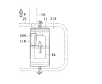
- the antenna 16 has a convex portion 16 ⁇ / b> K that protrudes inside the device case 21 when attached to the device case 21.
- the battery case 11X has the recessed part 11K in the position which fits with the convex part 16K of the antenna 16, when the battery attachment direction is a regular attachment direction among self outer wall surfaces.
- the upper direction in the vertical direction is the normal mounting direction P
- the antenna 16 is also in the upper direction in the vertical direction with respect to the device case 21. That is, they are connected along the normal mounting direction P.
- the projecting portion 16K of the antenna 16 protrudes to the inside of the device case 21.
- the battery case 11X when the battery case 11X is attached in a direction different from the normal attachment direction P, the battery case 11X interferes with the convex portion 16K of the antenna 16 attached in the normal attachment direction P. For this reason, when the battery case 11X is first attached to the device case 21, the antenna 16 cannot be attached in the regular attachment direction P. When the antenna 16 is first attached to the device case 21, the battery case 11X cannot be mounted inside the device case 21.
- the battery case 11X may be mounted inside the device case 21 in a direction different from the normal mounting direction P.
- the antenna 16 is connected to the outside of the field device 10, an error in the mounting direction of the antenna 16 can be found very easily by an operator. As a result, such a double error can be easily made. Can be avoided.
- SYMBOLS 10 Field apparatus, 11 ... Battery, 11A, 11B, 11C, 11D ... Hole, 11K ... Recessed part, 11T ... Convex part, 11X ... Battery case, 12 ... Mounting direction detection part, 12S ... Acceleration sensor, 13 ... Control part, 14 ... display unit, 14A, 14B, 14C, 14D ... hole, 14T ... convex part, 14X ... display panel, 15 ... radio part, 16, 16A, 16B, 16C ... antenna, 16K ... convex part, 21 ... equipment case, 21A ... Front cover, 21B ... Back cover, 21C, 21D ...
Landscapes
- Physics & Mathematics (AREA)
- General Physics & Mathematics (AREA)
- Battery Mounting, Suspending (AREA)
- Measuring Fluid Pressure (AREA)
- Testing Or Calibration Of Command Recording Devices (AREA)
- Programmable Controllers (AREA)
- Emergency Alarm Devices (AREA)
Abstract
電池(11)を収納するとともに、開口部から機器ケース(21)に挿入されて、機器ケース(21)の内側に取り付けられる電池ケース(11X)と、機器ケース(21)の内側に設けられて、電池(11)が予め設定されている正規取付方向となるよう、機器ケース(21)の設置方向に応じて電池ケース(11X)の取付方向を変更可能に取り付けるための複数の取付部(21I,21J)とを備える。これにより、機器ケースの設置方向に応じて電池ケースの取付方向を変更でき、電池寿命のバラツキを抑制できる。したがって、全体として電池交換に要するメンテナンス回数を削減することができ、内蔵電池のメンテナンスに要する作業負担を軽減できる。
Description
本発明は、プラントなどの設備に取り付けられて内蔵電池で動作するフィールド機器に関する。
プラントなどの設備では、圧力、流量、温度などの物理量を計測するフィールド機器として、内蔵電池で回路を動作させて、物理量を計測するとともに計測値を通知するためのデータ通信を行うフィールド機器を用いる場合がある(例えば、特許文献1など参照)。
このような内蔵電池で動作するフィールド機器では、内蔵電池の寿命に応じて、内蔵電池を交換する必要があり、メンテナンスの作業負担が発生する。
プラントにおけるフィールド機器のメンテナンスは、生産計画とスケジュール調整、交換備品の調達、メンテナンス作業人員や工数確保など、1回のメンテナンスにかかるプラント管理の負担やコストが大きい。このため、機械故障による生産停止のリスクを避ける一方で、不要なメンテナンスを極力実施せずに、メンテナンス回数を削減することが望まれる。したがって、電池のような交換部品を効率よく一括してメンテナンスするためには、寿命が明確で複数の交換部品の寿命が揃っていることが望ましい。
プラントにおけるフィールド機器のメンテナンスは、生産計画とスケジュール調整、交換備品の調達、メンテナンス作業人員や工数確保など、1回のメンテナンスにかかるプラント管理の負担やコストが大きい。このため、機械故障による生産停止のリスクを避ける一方で、不要なメンテナンスを極力実施せずに、メンテナンス回数を削減することが望まれる。したがって、電池のような交換部品を効率よく一括してメンテナンスするためには、寿命が明確で複数の交換部品の寿命が揃っていることが望ましい。
一方、電池の寿命については不確定要素があり、電池の仕様で明確化されている寿命まで使用できない場合も多い。このため、プラント管理者は、生産リスクを低減させるために、寿命よりも短い周期で交換を実施するか、あるいは、個々の電池寿命を確認しながら、それぞれに適切な時期を判断して交換することになる。前者の場合、まだ寿命に到達しておらず交換不要な電池までも交換することになる。一方、後者の場合、個々の電池寿命の確認に手間がかかる。したがって、いずれの場合にも、メンテナンス回数やその作業負担が増大するという問題点があった。
本発明はこのような課題を解決するためのものであり、内蔵する電池のメンテナンスに要する作業負担を軽減できるフィールド機器を提供することを目的としている。
このような目的を達成するために、本発明にかかるフィールド機器は、電池を収納するとともに、前記開口部から前記機器ケースに挿入されて、前記機器ケースの内側に取り付けられる電池ケースと、前記機器ケースの内側に設けられて、前記電池が予め設定されている正規取付方向となるよう、前記機器ケースの設置方向に応じて前記電池ケースの取付方向を変更可能に取り付けるための取付部とを備えている。
本発明によれば、電池が鉛直方向に対して一定の方向を指向する正規取付方向となるよう、機器ケースの設置方向に応じて電池ケースの取付方向を変更可能に取り付けることができる。これにより、各フィールド機器に内蔵された電池の寿命のバラツキが抑制されて、ほぼ同時期に電池寿命が到来する。したがって、全体として電池交換に要するメンテナンス回数を削減することができ、内蔵する電池のメンテナンスに要する作業負担を軽減することができる。
[発明の原理]
電池の寿命はその設置姿勢による影響が大きい。フィールド機器の場合、設置姿勢(取付時のフィールド機器自体の縦横方向)は、必ずしも一定に保たれるとは限らない。電池自体は、フィールド機器本体に設計された方向のみに内蔵取付されるので、フィールド機器自体の縦横方向に依存して電池の方向が決まってしまう。そして、その方向に依存して電池寿命が変動するので、これが電池寿命の不確定要素になってしまうことに、発明者は着眼した。
電池の寿命はその設置姿勢による影響が大きい。フィールド機器の場合、設置姿勢(取付時のフィールド機器自体の縦横方向)は、必ずしも一定に保たれるとは限らない。電池自体は、フィールド機器本体に設計された方向のみに内蔵取付されるので、フィールド機器自体の縦横方向に依存して電池の方向が決まってしまう。そして、その方向に依存して電池寿命が変動するので、これが電池寿命の不確定要素になってしまうことに、発明者は着眼した。
そして、フィールド機器本体への電池の内蔵取付方向を、フィールド機器自体のプラントへの取付後においても選択変更できる構造にすることで、上記不確定要素を削減できることに想到した。なお、プラントではコンプレッサーなどの振動を受けやすい環境もあるため、電池の内蔵取付方向を選択変更できる構造においても、確実に固定できることが望まれる。例えば、選択変更できる方向を90°(縦横に対応)の最低限にすることで、低コストで確実な取付構造になるのが好適である。
次に、本発明の実施の形態について図面を参照して説明する。
[第1の実施の形態]
まず、図1A,図1B,図2,図3A,図3Bを参照して、本発明の第1の実施の形態にかかるフィールド機器10について説明する。
[第1の実施の形態]
まず、図1A,図1B,図2,図3A,図3Bを参照して、本発明の第1の実施の形態にかかるフィールド機器10について説明する。
フィールド機器10は、プラントなどの設備で用いられて、圧力、流量、温度などの物理量を計測するフィールド機器である。
このフィールド機器10は、機器ケース21、前面カバー21A、背面カバー21B、検出部22、および連結部23から構成されている。
このフィールド機器10は、機器ケース21、前面カバー21A、背面カバー21B、検出部22、および連結部23から構成されている。
機器ケース21は、各種電子回路が内蔵される筒状または箱状の金属筐体からなり、一方の開口部21Cに前面カバー21Aが取り付けられ、他方の開口部21Dに背面カバー21Bが取り付けられている。
機器ケース21の中央付近には、連結部23を介して検出部22が接続されており、検出部22まで導かれた流体や気体などの対象物に関する物理量が、検出部22に内蔵されたセンサで検出される。
機器ケース21の中央付近には、連結部23を介して検出部22が接続されており、検出部22まで導かれた流体や気体などの対象物に関する物理量が、検出部22に内蔵されたセンサで検出される。
機器ケース21の開口部21D側内部には、電池11を収容した電池ケース11Xが取り付けられており、機器ケース21の開口部21C側内部には、表示部14を収容した表示パネル14Xが取り付けられている。
また、機器ケース21の外面には、無線通信用のアンテナ16が固定されている。
また、機器ケース21の外面には、無線通信用のアンテナ16が固定されている。
図3A,図3Bに示すように、電池ケース11Xには、2つの電池11が電極方向を揃えて収納されている。この電池ケース11Xの周辺部には、複数の穴11A,11B,11C,11Dが同一円周上に形成されている。
一方、機器ケース21の内壁21Xに電池ケース11Xを取り付けるための取付部21I,21Jが設けられている。
一方、機器ケース21の内壁21Xに電池ケース11Xを取り付けるための取付部21I,21Jが設けられている。
この取付部21I,21Jは、内壁21Xの互いに対向する一部を突出させて形成されており、電池ケース11Xの穴11A,11B,11C,11Dを貫通したネジ21Mが、この取付部21I,21Jに形成されているネジ穴に螺合することにより、電池ケース11Xが内壁21Xにネジ止めされる。
ここで、取付部21I,21Jは、内壁21Xの左右方向に互いに対向して設けられており、電池ケース11Xにはこれら内壁21Xと対応する4つの穴11A,11B,11C,11Dが、互いに直交する角度で設けられている。
これにより、穴11A,11B,11C,11Dのうちから、取付部21I,21Jにネジ止めする2つの穴を選択することにより、電池ケース11Xを回転させて、4種類の取付方向のうちから任意の取付方向で機器ケース21の内側に取り付けることができる。
これにより、穴11A,11B,11C,11Dのうちから、取付部21I,21Jにネジ止めする2つの穴を選択することにより、電池ケース11Xを回転させて、4種類の取付方向のうちから任意の取付方向で機器ケース21の内側に取り付けることができる。
図4Aに示すように、フィールド機器10が正立状態で設置されている場合、すなわち機器ケース21が検出部22の上方に位置する状態で設置されている場合、前述した図3Aと同様にして、取付部21Iに穴11Aをネジ止めするとともに、取付部21Jに穴11Bをネジ止めすることにより、電池11の電池取付方向Bを正規取付方向Pに沿って取り付けることができる。
ここでは、電池11の中心位置から正電極11Pの方向を電池取付方向Bとし、鉛直方向上方を正規取付方向Pとして定義した場合を例として説明する。なお、電池11の寿命が最も長くなる取付方向は、電池11の形状や内部構造などの要因によって決定されるため、使用する電池の種別に応じて予め決定しておけばよい。
一方、図4Bに示すように、フィールド機器10が横倒状態で設置されている場合、すなわち機器ケース21が検出部22の左側に位置する状態で設置されている場合、前述した図3Aと同様の取付方向で電池ケース11Xを取り付けた場合、電池取付方向Bは左側を向くことになり、正規取付方向Pとは異なる。この場合には、取付部21Iに穴11Dをネジ止めするとともに、取付部21Jに穴11Cをネジ止めすることにより、電池11の電池取付方向Bを正規取付方向Pに沿って取り付けることができる。
[第1の実施の形態の効果]
したがって、本実施の形態によれば、電池11が鉛直方向に対して一定の方向を指向する正規取付方向Pとなるよう、機器ケース21の設置方向に応じて電池ケース11Xの取付方向を変更可能に取り付けることができる。
したがって、本実施の形態によれば、電池11が鉛直方向に対して一定の方向を指向する正規取付方向Pとなるよう、機器ケース21の設置方向に応じて電池ケース11Xの取付方向を変更可能に取り付けることができる。
本実施の形態では、電池ケース11Xに4つの穴11A,11B,11C,11Dを設けて、4種類の取付方向を選択可能とした場合を例として説明したが、これに限定されるものではなく、フィールド機器10の設置方向に合わせて、穴を形成すればよい。例えば、フィールド機器10を左右の横倒状態のいずれかで設置する場合には、穴11A,11Dのみを設けて、左右2種類の取付方法を選択可能とすればよい。また、例えば45゜単位でフィールド機器10が設置される場合、電池ケース11Xに45゜ごとに8つ穴を形成すればよい。
また、以上では電池ケース11Xに設けた穴のいずれかをネジ止め用として選択する場合を例として説明したが、機器ケース21の内壁21Xに設けた取付部のいずれかをネジ止め用として選択するようにしてもよい。具体的には、電池ケース11Xに2つの穴を形成し、機器ケース21の内壁21Xに、90゜ごとに4つの取付部を形成した場合でも、図3A,図3Bの構成と同様に、4種類の取付方向を選択することができる。
なお、電池ケース11Xの穴と機器ケース21の内壁21Xの取付部の数や角度については、これらの例に限定されるものではなく、フィールド機器10の設置方向と正規取付方向との関係に応じて、それぞれの数や角度を選択すればよい。
なお、電池ケース11Xの穴と機器ケース21の内壁21Xの取付部の数や角度については、これらの例に限定されるものではなく、フィールド機器10の設置方向と正規取付方向との関係に応じて、それぞれの数や角度を選択すればよい。
[第2の実施の形態]
次に、図5,図6A,および図6Bを参照して、本発明の第2の実施の形態にかかるフィールド機器10について説明する。
次に、図5,図6A,および図6Bを参照して、本発明の第2の実施の形態にかかるフィールド機器10について説明する。
本実施の形態は、第1の実施の形態に加えて、電池11の取付方向を検出する取付方向検出部12を設け、電池取付方向が正規取付方向と異なる場合、アラームを通知するようにした場合について説明する。
フィールド機器10には、電子回路として、取付方向検出部12、制御部13、表示部14、無線部15、およびアンテナ16が設けられている。
取付方向検出部12は、電池11(電池ケース11X)の取付方向を検出する機能を有している。取付方向検出部12の具体例としては、電池ケース11Xに加速度センサ12Sを取り付け、この加速度センサ12Sからの出力に基づいて鉛直方向に対する電池取付方向Bを検出すればよい。
取付方向検出部12は、電池11(電池ケース11X)の取付方向を検出する機能を有している。取付方向検出部12の具体例としては、電池ケース11Xに加速度センサ12Sを取り付け、この加速度センサ12Sからの出力に基づいて鉛直方向に対する電池取付方向Bを検出すればよい。
制御部13は、CPUや専用の制御回路からなり、検出部22のセンサ(図示せず)から検出結果を取得する機能と、この検出結果を無線部15から無線電波により送信する機能と、この検出結果を表示部14で表示する機能とを有している。
これに加え、制御部13は、取付方向検出部12で検出された電池取付方向Bが正規取付方向Pであるか否かを確認する機能と、電池取付方向Bが正規取付方向Pと異なる場合、無線部15から無線電波によりアラーム情報を送信することによりアラームを通知する機能と、電池取付方向Bが正規取付方向Pと異なる場合、表示部14でアラーム表示を行うことによりアラームを通知する機能とを有している。
これに加え、制御部13は、取付方向検出部12で検出された電池取付方向Bが正規取付方向Pであるか否かを確認する機能と、電池取付方向Bが正規取付方向Pと異なる場合、無線部15から無線電波によりアラーム情報を送信することによりアラームを通知する機能と、電池取付方向Bが正規取付方向Pと異なる場合、表示部14でアラーム表示を行うことによりアラームを通知する機能とを有している。
表示部14は、LEDやLCDなどの表示装置からなり、制御部13からの指示に応じて検出結果やアラームなどの各種情報を表示する機能を有している。
無線部15は、専用の無線通信回路からなり、制御部13からの指示に応じて検出結果やアラームなどの各種情報を、アンテナ16から無線電波で送信する機能を有している。
なお、本実施の形態にかかるフィールド機器10におけるこの他の構成については、第1の実施の形態と同様であり、ここでの詳細な説明は省略する。
無線部15は、専用の無線通信回路からなり、制御部13からの指示に応じて検出結果やアラームなどの各種情報を、アンテナ16から無線電波で送信する機能を有している。
なお、本実施の形態にかかるフィールド機器10におけるこの他の構成については、第1の実施の形態と同様であり、ここでの詳細な説明は省略する。
[第2の実施の形態の動作]
次に、図7を参照して、本実施の形態にかかるフィールド機器10の動作について説明する。
次に、図7を参照して、本実施の形態にかかるフィールド機器10の動作について説明する。
まず、制御部13は、取付方向検出部12を制御して電池取付方向Bを検出し(ステップ100)、予め設定されている正規取付方向Pと比較する(ステップ101)。この際、加速度センサで電池取付方向Bを検出した場合、検出結果として3軸方向角度が得られる。したがって、この検出結果が、予め設定されている正規取付方向Pを示す角度範囲に含まれるか否かを判定することにより、電池取付方向Bが正規取付方向Pであるか否かを確認することができる。
ここで、検出結果が、予め設定されている正規取付方向Pを示す角度範囲に含まれており、電池取付方向Bが正規取付方向Pである場合(ステップ101:YES)、制御部13は、アラーム通知処理を行うことなく、一連の電池取付方向判定処理を終了する。
一方、予め設定されている正規取付方向Pを示す角度範囲に含まれておらず、電池取付方向Bが正規取付方向Pでない場合(ステップ101:NO)、制御部13は、アラーム通知処理として、無線部15から無線電波によりアラーム情報を送信するとともに(ステップ102)、表示部14でアラーム表示を行い(ステップ103)、一連の電池取付方向判定処理を終了する。
一方、予め設定されている正規取付方向Pを示す角度範囲に含まれておらず、電池取付方向Bが正規取付方向Pでない場合(ステップ101:NO)、制御部13は、アラーム通知処理として、無線部15から無線電波によりアラーム情報を送信するとともに(ステップ102)、表示部14でアラーム表示を行い(ステップ103)、一連の電池取付方向判定処理を終了する。
[第2の実施の形態の効果]
このように、本実施の形態によれば、電池11の取付方向を、正規取付方向Pと異なる方向に誤って取り付けた場合には、フィールド機器10からコントローラなどの上位装置(図示せず)へアラーム情報が自動的に送信されるため、あるいはフィールド機器10の表示部14でアラーム表示されるため、作業者は適切な対応をとることができる。
なお、正規取付方向Pを示す角度範囲については、角度範囲と電池寿命のばらつき程度との関係や、電池寿命のばらつき程度と実際のメンテナンス周期との関係などを考慮して、予め設定しておけばよい。
このように、本実施の形態によれば、電池11の取付方向を、正規取付方向Pと異なる方向に誤って取り付けた場合には、フィールド機器10からコントローラなどの上位装置(図示せず)へアラーム情報が自動的に送信されるため、あるいはフィールド機器10の表示部14でアラーム表示されるため、作業者は適切な対応をとることができる。
なお、正規取付方向Pを示す角度範囲については、角度範囲と電池寿命のばらつき程度との関係や、電池寿命のばらつき程度と実際のメンテナンス周期との関係などを考慮して、予め設定しておけばよい。
[第3の実施の形態]
次に、図8A,図8Bを参照して、本発明の第3の実施の形態にかかるフィールド機器10について説明する。
次に、図8A,図8Bを参照して、本発明の第3の実施の形態にかかるフィールド機器10について説明する。
第2の実施の形態では、加速度センサを利用して電池11の電池取付方向を検出する場合を例として説明した。本実施の形態では、例えばメカニカルスイッチや光学スイッチなどの検出スイッチを利用して、フィールド機器10に対する相対的な電池取付方向を検出する場合について説明する。
本実施の形態は、第1の実施の形態に加えて、取付方向検出部12は、機器ケース21に対する電池ケース11Xの相対的な取付方向を電池取付方向として検出する機能を有している。
また、制御部13は、取付方向検出部12で検出された電池取付方向が、フィールド機器10から見た正規取付方向Pを示す整合方向であるか否かを判定することにより、電池取付方向Bが正規取付方向Pであるか否かを確認する機能を有している。
また、制御部13は、取付方向検出部12で検出された電池取付方向が、フィールド機器10から見た正規取付方向Pを示す整合方向であるか否かを判定することにより、電池取付方向Bが正規取付方向Pであるか否かを確認する機能を有している。
図8A,図8Bに示すように、本実施の形態において、電池ケース11Xのうち、取付部21I,21J側の面に凸部11Tが設けられている。一方、機器ケース21内部には、電池ケース11Xと対向して基板(PCB)31が固定されており、この基板31上に、取付方向検出部12を構成する4つの検出スイッチ31A,31B,31C,31Dが実装されている。
これら検出スイッチ31A,31B,31C,31Dは、電池ケース11Xを取付部21I,21Jにネジ止めした際、凸部11Tと接触して作動する位置にそれぞれ実装されている。
これら検出スイッチ31A,31B,31C,31Dは、電池ケース11Xを取付部21I,21Jにネジ止めした際、凸部11Tと接触して作動する位置にそれぞれ実装されている。
なお、本実施の形態にかかるフィールド機器10におけるこの他の構成については、第1の実施の形態と同様であり、ここでの詳細な説明は省略する。また、動作については、図7のステップ100において、加速度センサに代えて検出スイッチ31A,31B,31C,31Dで電池取付方向を検出する以外は、第2の実施の形態と同様であり、ここでの詳細な説明は省略する。
ここでは、フィールド機器10に対する電池取付方向として、Q1,Q2,Q3,Q4の4つの相対取付方向が定義されている。
すなわち、相対取付方向Q1は、取付部21I,21Jに対して穴11C,11Bがネジ止めされた状態において、電池取付方向Bが指向する方向を示しており、この場合には凸部11Tで検出スイッチ31Aが作動することになる。また、相対取付方向Q2は、取付部21I,21Jに対して穴11D,11Aがネジ止めされた状態において、電池取付方向Bが指向する方向を示しており、この場合には凸部11Tで検出スイッチ31Bが作動することになる。
すなわち、相対取付方向Q1は、取付部21I,21Jに対して穴11C,11Bがネジ止めされた状態において、電池取付方向Bが指向する方向を示しており、この場合には凸部11Tで検出スイッチ31Aが作動することになる。また、相対取付方向Q2は、取付部21I,21Jに対して穴11D,11Aがネジ止めされた状態において、電池取付方向Bが指向する方向を示しており、この場合には凸部11Tで検出スイッチ31Bが作動することになる。
同様にして、相対取付方向Q3は、取付部21I,21Jに対して穴11A,11Dがネジ止めされた状態において、電池取付方向Bが指向する方向を示しており、この場合には凸部11Tで検出スイッチ31Cが作動することになる。また、相対取付方向Q4は、取付部21I,21Jに対して穴11B,11Cがネジ止めされた状態において、電池取付方向Bが指向する方向を示しており、この場合には凸部11Tで検出スイッチ31Dが作動することになる。
前述の図4A,図4Bに示したように、フィールド機器10は、正立状態以外の方向で設置される場合があるが、正立状態など、予め固定された方向で設置される場合も多い。このような場合には、正規取付方向Pがフィールド機器10の設置方向に対して固定的に決定される。例えば、図4Aに示したように、フィールド機器10が正立状態で設置された場合、フィールド機器10から見た正規取付方向を示す整合方向は、図8A,図8Bにおける相対取付方向Q1となる。
したがって、電池ケース11Xが、このような相対取付方向Q1でフィールド機器10へ取り付けられているか否かを、検出スイッチで確認すれば、電池11の取付方向の誤り有無を確認することができる。
したがって、電池ケース11Xが、このような相対取付方向Q1でフィールド機器10へ取り付けられているか否かを、検出スイッチで確認すれば、電池11の取付方向の誤り有無を確認することができる。
図8A,図8Bの例では、凸部11Tにより押圧された検出スイッチ31Aの作動が取付方向検出部12で検出されることから、制御部13は、図10のような電池取付方向と作動検出スイッチとの対応関係を示すテーブルに基づいて、電池が相対取付方向Q1を指向していることが確認できる。したがって、この場合は、フィールド機器10が正立状態で設置された場合の整合方向、すなわち相対取付方向Q1と一致していることから、結果として、電池取付方向が正規取付方向であると判定される。
[第3の実施の形態の効果]
このように、本実施の形態によれば、フィールド機器10が予め固定された方向で設置される場合、第2の実施の形態で説明したような、鉛直方向を基準とする3軸方向角度を検出できなくても、機器ケース21に対する電池11の相対的な取付方向により、電池11の取付方向の誤り有無を確認することができる。
したがって、比較的高価な加速度センサを必要とすることなく、安価な検出スイッチであっても、電池11の取付方向の誤り有無を確認することができる。
このように、本実施の形態によれば、フィールド機器10が予め固定された方向で設置される場合、第2の実施の形態で説明したような、鉛直方向を基準とする3軸方向角度を検出できなくても、機器ケース21に対する電池11の相対的な取付方向により、電池11の取付方向の誤り有無を確認することができる。
したがって、比較的高価な加速度センサを必要とすることなく、安価な検出スイッチであっても、電池11の取付方向の誤り有無を確認することができる。
[第4の実施の形態]
次に、図11および図12を参照して、本発明の第4の実施の形態にかかるフィールド機器10について説明する。
次に、図11および図12を参照して、本発明の第4の実施の形態にかかるフィールド機器10について説明する。
第3の実施の形態では、検出スイッチを用いてフィールド機器10に対する電池11の相対的な電池取付方向を検出する場合を例として説明した。本実施の形態では、アンテナ16の取付方向を検出して電池取付方向と比較することにより、電池取付方向が正規取付方向であるか否かを確認する場合について説明する。
一般に、アンテナ16は、電波伝搬状態を良好な状態に保つため、鉛直方向上方に向けて立設される場合が多く、フィールド機器10の設置方向に左右されない。このため、アンテナ16の取付方向を検出すれば、鉛直方向を特定することができ、結果として、フィールド機器10から見た正規取付方向Pを示す整合方向を特定することができる。
本実施の形態において、取付方向検出部12は、機器ケース21に取り付けられたアンテナのアンテナ取付方向を検出する機能を有している。
制御部13は、取付方向検出部12で検出されたアンテナ取付方向と電池取付方向と比較することにより、電池取付方向が正規取付方向であるか否かを確認する機能を有している。
制御部13は、取付方向検出部12で検出されたアンテナ取付方向と電池取付方向と比較することにより、電池取付方向が正規取付方向であるか否かを確認する機能を有している。
フィールド機器10の設置方向を変更しても、アンテナ16を鉛直方向上方に向けて立設するための構成として、機器ケース21の外面には、複数の接続穴が設けられている。
本実施の形態では、これら接続穴に、取付方向検出部12を構成する検出スイッチ32A,32B,32Cを設け、それぞれの接続穴に対するアンテナ16の取付有無を検出する。したがって、図11において、フィールド機器10が正立状態で設置される場合、機器ケース21には、アンテナ16Aが接続されるため、検出スイッチ32Aが作動する。一方、フィールド機器10が横倒状態で設置される場合、機器ケース21には、アンテナ16Bまたはアンテナ16Cが接続されるため、検出スイッチ32Bまたは検出スイッチ32Cが作動する。
本実施の形態では、これら接続穴に、取付方向検出部12を構成する検出スイッチ32A,32B,32Cを設け、それぞれの接続穴に対するアンテナ16の取付有無を検出する。したがって、図11において、フィールド機器10が正立状態で設置される場合、機器ケース21には、アンテナ16Aが接続されるため、検出スイッチ32Aが作動する。一方、フィールド機器10が横倒状態で設置される場合、機器ケース21には、アンテナ16Bまたはアンテナ16Cが接続されるため、検出スイッチ32Bまたは検出スイッチ32Cが作動する。
ここで、アンテナ16の指向する方向が電池11の正規取付方向Pであるとすると、図11に示すように、アンテナ16Aが接続されるフィールド機器10が正立状態で設置された場合、その正規取付方向はP1となり、電池11を正規取付方向P1に取り付けるためには、フィールド機器10に対して電池11を相対取付方向Q1で取り付ければよいことがわかる。
また、アンテナ16Bが接続されるフィールド機器10が右横倒状態で設置された場合、その正規取付方向はP2となり、電池11を正規取付方向P2に取り付けるためには、フィールド機器10に対して電池11を相対取付方向Q2で取り付ければよいことがわかる。同様に、アンテナ16Cが接続されるフィールド機器10が左横倒状態で設置された場合、その正規取付方向はP3となり、電池11を正規取付方向P3に取り付けるためには、フィールド機器10に対して電池11を相対取付方向Q3で取り付ければよいことがわかる。
これにより、図11に示すように、アンテナ16Aの接続が検出スイッチ32Aの作動により検出された場合、検出スイッチ31Aの作動が確認されれば、電池11は、正規取付方向P1を指向していることを確認できる。また、アンテナ16Bの接続が検出スイッチ32Bの作動により検出された場合、検出スイッチ31Bの作動が確認されれば、電池11は、正規取付方向P2を指向していることを確認できる。アンテナ16Cの接続が検出スイッチ32Cの作動により検出された場合、検出スイッチ31Cの作動が確認されれば、電池11は、正規取付方向P3を指向していることを確認できる。
したがって、制御部13は、図12のようなアンテナ取付方向と電池取付方向との対応関係を示すテーブルに基づいて、電池ケース11Xの電池取付方向Bを検出する検出スイッチ31A,31B,31Cの作動状況と、アンテナ16のアンテナ取付方向を検出する検出スイッチ32A,32B,32Cの作動状況とを比較することにより、電池取付方向が正規取付方向であるか否かを確認することができる。なお、ここでは、フィールド機器10が倒立状態で設置される場合はないことを前提としている。
[第4の実施の形態の動作]
次に、図13を参照して、本実施の形態にかかるフィールド機器10の動作について説明する。
次に、図13を参照して、本実施の形態にかかるフィールド機器10の動作について説明する。
まず、制御部13は、取付方向検出部12から取得した検出スイッチ31A,31B,31Cの作動状態に基づいて、電池取付方向検出するとともに(ステップ200)、取付方向検出部12から取得した検出スイッチ32A,32B,32Cの作動状態に基づいて、アンテナ取付方向を検出する(ステップ201)。
この後、制御部13は、電池取付方向とアンテナ取付方向とを比較する(ステップ202)。ここで、両者が図12のようなアンテナ取付方向と電池取付方向との対応関係にあり、電池取付方向とアンテナ取付方向とが一致する場合(ステップ202:YES)、制御部13は、アラーム処理を行うことなく、一連の電池取付方向判定処理を終了する。
一方、両者が図12のようなアンテナ取付方向と電池取付方向との対応関係にはなく、電池取付方向とアンテナ取付方向とが一致しない場合(ステップ202:NO)、制御部13は、無線部15から無線電波によりアラーム通知を送信するとともに(ステップ203)、表示部14でアラーム表示を行い(ステップ204)、一連の電池取付方向判定処理を終了する。
[第4の実施の形態の効果]
このように、本実施の形態によれば、アンテナ16が予め固定された方向で設置される場合、第2の実施の形態で説明したような、鉛直方向を基準とする3軸方向角度を検出できなくても、フィールド機器10に対する電池11の相対的な取付方向と、フィールド機器10に対するアンテナ取付方向とにより、電池11の取付方向の誤り有無を確認することができる。
したがって、比較的高価な加速度センサを必要とすることなく、安価な検出スイッチであっても、電池11の取付方向の誤り有無を確認することができる。
このように、本実施の形態によれば、アンテナ16が予め固定された方向で設置される場合、第2の実施の形態で説明したような、鉛直方向を基準とする3軸方向角度を検出できなくても、フィールド機器10に対する電池11の相対的な取付方向と、フィールド機器10に対するアンテナ取付方向とにより、電池11の取付方向の誤り有無を確認することができる。
したがって、比較的高価な加速度センサを必要とすることなく、安価な検出スイッチであっても、電池11の取付方向の誤り有無を確認することができる。
[第5の実施の形態]
次に、図14A,図14Bを参照して、本発明の第5の実施の形態にかかるフィールド機器10について説明する。
次に、図14A,図14Bを参照して、本発明の第5の実施の形態にかかるフィールド機器10について説明する。
第4の実施の形態では、アンテナ16の取付方向を検出して電池取付方向と比較することにより、電池取付方向が正規取付方向であるか否かを確認する場合を例として説明した。本実施の形態では、表示部14の取付方向を検出して電池取付方向と比較することにより、電池取付方向が正規取付方向であるか否かを確認する場合について説明する。
一般に、表示部14は、作業者の視認性を良好な状態に保つため、鉛直方向上方に向けて正立状態で取り付けられる場合が多く、フィールド機器10の設置方向に左右されない。このため、表示部14の取付方向を検出すれば、鉛直方向を特定することができ、結果として、フィールド機器10から見た正規取付方向Pを示す整合方向を特定することができる。
本実施の形態において、取付方向検出部12は、機器ケース21に取り付けられた表示部の表示部取付方向を検出する機能を有している。
制御部13は、取付方向検出部12で検出された表示部取付方向と電池取付方向と比較することにより、電池取付方向が正規取付方向であるか否かを確認する機能を有している。
制御部13は、取付方向検出部12で検出された表示部取付方向と電池取付方向と比較することにより、電池取付方向が正規取付方向であるか否かを確認する機能を有している。
図14A,図14Bに示すように、本実施の形態において、表示パネル14Xには、表示部14が収納されている。この表示パネル14Xの周辺部には、複数の穴14A,14B,14C,14Dが同一円周上に形成されている。
一方、機器ケース21の内壁21Xに表示パネル14Xを取り付けるための取付部21K,21Lが設けられている。
一方、機器ケース21の内壁21Xに表示パネル14Xを取り付けるための取付部21K,21Lが設けられている。
この取付部21K,21Lは、取付部21I,21Jと同様に、内壁21Xの互いに対向する一部を突出させて形成されており、表示パネル14Xの穴14A,14B,14C,14Dを貫通したネジ21Nが、この取付部21K,21Lに形成されているネジ穴に螺合することにより、表示パネル14Xが内壁21Xにネジ止めされる。
ここで、取付部21K,21Lは、内壁21Xの左右方向に互いに対向して設けられており、表示パネル14Xにはこれら内壁21Xと対応する4つの穴14A,14B,14C,14Dが、互いに直交する角度で設けられている。
これにより、穴14A,14B,14C,14Dのうちから、取付部21K,21Lにネジ止めする2つの穴を選択することにより、表示パネル14Xを回転させて、任意の取付方向で機器ケース21の内側に取り付けることができる。
これにより、穴14A,14B,14C,14Dのうちから、取付部21K,21Lにネジ止めする2つの穴を選択することにより、表示パネル14Xを回転させて、任意の取付方向で機器ケース21の内側に取り付けることができる。
また、表示パネル14Xのうち、取付部21K,21L側の面に凸部14Tが設けられている。一方、機器ケース21内部には、表示パネル14Xと対向して基板(PCB)33が固定されており、この基板33上に、取付方向検出部12を構成する4つの検出スイッチ33A,33B,33C,33Dが実装されている。
これら検出スイッチ33A,33B,33C,33Dは、表示パネル14Xを取付部21K,21Lにネジ止めした際、凸部14Tと接触して作動する位置にそれぞれ実装されている。
これら検出スイッチ33A,33B,33C,33Dは、表示パネル14Xを取付部21K,21Lにネジ止めした際、凸部14Tと接触して作動する位置にそれぞれ実装されている。
なお、本実施の形態にかかるフィールド機器10におけるこの他の構成については、第1の実施の形態と同様であり、ここでの詳細な説明は省略する。また、動作については、図13のステップ201において、アンテナ取付方向に代えて検出スイッチ33A,33B,33C,33Dで表示部取付方向を検出する以外は、第4の実施の形態と同様であり、ここでの詳細な説明は省略する。
ここでは、フィールド機器10に対する表示部取付方向として、R1,R2,R3,R4の4つの相対取付方向が定義されている。
すなわち、相対取付方向R1は、取付部21K,21Lに対して穴14C,14Bがネジ止めされた状態において、表示部取付方向Dが指向する方向を示しており、この場合には凸部14Tで検出スイッチ33Aが作動することになる。また、相対取付方向R2は、取付部21K,21Lに対して穴14D,14Aがネジ止めされた状態において、表示部取付方向Dが指向する方向を示しており、この場合には凸部14Tで検出スイッチ33Bが作動することになる。
すなわち、相対取付方向R1は、取付部21K,21Lに対して穴14C,14Bがネジ止めされた状態において、表示部取付方向Dが指向する方向を示しており、この場合には凸部14Tで検出スイッチ33Aが作動することになる。また、相対取付方向R2は、取付部21K,21Lに対して穴14D,14Aがネジ止めされた状態において、表示部取付方向Dが指向する方向を示しており、この場合には凸部14Tで検出スイッチ33Bが作動することになる。
同様にして、相対取付方向R3は、取付部21K,21Lに対して穴14A,14Dがネジ止めされた状態において、表示部取付方向Dが指向する方向を示しており、この場合には凸部14Tで検出スイッチ33Cが作動することになる。また、相対取付方向R4は、取付部21K,21Lに対して穴14B,14Cがネジ止めされた状態において、表示部取付方向Dが指向する方向を示しており、この場合には凸部14Tで検出スイッチ33Dが作動することになる。
ここで、表示部14の指向する方向が電池11の正規取付方向Pであるとすると、フィールド機器10が正立状態で設置された場合、図15Aに示すように、表示部取付方向Dが相対取付方向R1を指向していることになる。したがって、電池11を正規取付方向Pに取り付けるためには、前述の図9Aに示すように、フィールド機器10に対して電池11を相対取付方向Q1、すなわち相対取付方向R1と一致した方向で取り付ければよいことがわかる。
また、フィールド機器10が右横倒状態で設置された場合、図15Bに示すように、表示部取付方向Dが相対取付方向R2を指向していることになる。したがって、電池11を正規取付方向Pに取り付けるためには、前述の図9Bに示すように、フィールド機器10に対して電池11を相対取付方向Q2、すなわち相対取付方向R2一致した方向で取り付ければよいことがわかる。
また、フィールド機器10が左横倒状態で設置された場合、図15Cに示すように、表示部取付方向Dが相対取付方向R3を指向していることになる。したがって、電池11を正規取付方向Pに取り付けるためには、前述の図9Cに示すように、フィールド機器10に対して電池11を相対取付方向Q3、すなわち相対取付方向R3一致した方向で取り付ければよいことがわかる。
また、フィールド機器10が右横倒状態で設置された場合、図15Dに示すように、表示部取付方向Dが相対取付方向R4を指向していることになる。したがって、電池11を正規取付方向Pに取り付けるためには、前述の図9Dに示すように、フィールド機器10に対して電池11を相対取付方向Q4、すなわち相対取付方向R4一致した方向で取り付ければよいことがわかる。
したがって、制御部13は、図16のような表示部取付方向と電池取付方向との対応関係を示すテーブルに基づいて、電池ケース11Xの電池取付方向Bを検出する検出スイッチ31A,31B,31C,31Dの作動状況と、表示パネル14Xの表示部取付方向Dを検出する検出スイッチ33A,33B,33C,33Dの作動状況とを比較することにより、電池取付方向が正規取付方向であるか否かを確認することができる。
[第5の実施の形態の効果]
このように、本実施の形態によれば、表示部14が予め固定された方向で設置される場合、第2の実施の形態で説明したような、鉛直方向を基準とする3軸方向角度を検出できなくても、フィールド機器10に対する電池11の相対的な取付方向と、フィールド機器10に対する表示部取付方向とにより、電池11の取付方向の誤り有無を確認することができる。
したがって、比較的高価な加速度センサを必要とすることなく、安価な検出スイッチであっても、電池11の取付方向の誤り有無を確認することができる。
このように、本実施の形態によれば、表示部14が予め固定された方向で設置される場合、第2の実施の形態で説明したような、鉛直方向を基準とする3軸方向角度を検出できなくても、フィールド機器10に対する電池11の相対的な取付方向と、フィールド機器10に対する表示部取付方向とにより、電池11の取付方向の誤り有無を確認することができる。
したがって、比較的高価な加速度センサを必要とすることなく、安価な検出スイッチであっても、電池11の取付方向の誤り有無を確認することができる。
[第6の実施の形態]
次に、図17A,図17B,図18A,および図18Bを参照して、本発明の第6の実施の形態にかかるフィールド機器10について説明する。
次に、図17A,図17B,図18A,および図18Bを参照して、本発明の第6の実施の形態にかかるフィールド機器10について説明する。
前述したように、アンテナ16は、電波伝搬状態を良好な状態に保つため、鉛直方向上方に向けて立設される場合が多く、フィールド機器10の設置方向に左右されない。このため、例えばアンテナ16の指向する方向を電池11の正規取付方向Pとすることができる。本実施の形態は、このような観点から、第1の実施の形態に加えて、電池11の取付方向とアンテナ16の取付方向が一致していない場合、電池11またはアンテナ16をフィールド機器10に取り付けられないよう構成した場合について説明する。
本実施の形態において、アンテナ16は、機器ケース21に取り付けた状態で機器ケース21の内側に突出する凸部16Kを有している。
また、電池ケース11Xは、自己の外壁面のうち、電池取付方向が正規取付方向である場合にアンテナ16の凸部16Kと嵌合する位置に、凹部11Kを有している。
また、電池ケース11Xは、自己の外壁面のうち、電池取付方向が正規取付方向である場合にアンテナ16の凸部16Kと嵌合する位置に、凹部11Kを有している。
図17A,図17Bに示すように、フィールド機器10が正立状態以外の方向で設置される場合、鉛直方向上方が正規取付方向Pとなり、アンテナ16も機器ケース21に対して、鉛直方向上方、すなわち正規取付方向Pに沿って接続される。この際、アンテナ16の凸部16Kが機器ケース21の内側に突出する状態となる。
したがって、図18Aに示すように、電池ケース11Xを正規取付方向Pに取り付ける場合、凹部11Kが正規取付方向Pに取り付けられているアンテナ16の凸部16Kと勘合して、電池ケース11Xが凸部16Kと干渉しないため、電池ケース11Xを機器ケース21内部に取り付けることが可能となる。
一方、図18Bに示すように、電池ケース11Xを正規取付方向Pとは異なる方向に取り付ける場合、電池ケース11Xが正規取付方向Pに取り付けられているアンテナ16の凸部16Kと干渉する。このため、電池ケース11Xを先に機器ケース21に取り付けた場合には、アンテナ16を正規取付方向Pに取り付けることができなくなり、アンテナ16を先に機器ケース21に取り付けた場合には、電池ケース11Xを機器ケース21内部に取り付けることができない。
[第6の実施の形態の効果]
このように、本実施の形態によれば、電池ケース11Xを取り付ける場合、その取付方向が正規取付方向Pとは異なる場合、電池ケース11Xがアンテナ16の凸部と干渉するため、機器ケース21内部に電池ケース11Xを取り付けることができない。したがって、第2~第5の実施の形態で説明したような、取付方向検出部12を必要とすることなく、電池ケース11Xの取付作業時に、取付方向の誤りを確認することができる。
このように、本実施の形態によれば、電池ケース11Xを取り付ける場合、その取付方向が正規取付方向Pとは異なる場合、電池ケース11Xがアンテナ16の凸部と干渉するため、機器ケース21内部に電池ケース11Xを取り付けることができない。したがって、第2~第5の実施の形態で説明したような、取付方向検出部12を必要とすることなく、電池ケース11Xの取付作業時に、取付方向の誤りを確認することができる。
なお、アンテナ16の取付方向に誤りがある場合、電池ケース11Xが正規取付方向Pとは異なる方向で機器ケース21内部に取り付けられる場合がある。しかし、アンテナ16はフィールド機器10の外部に接続されるため、アンテナ16の取付方向の誤りを、作業者が極めて容易に発見することができるため、結果としてこのような二重の誤りを容易に回避できる。
[実施の形態の拡張]
以上、実施形態を参照して本発明を説明したが、本発明は上記実施形態に限定されるものではない。本発明の構成や詳細には、本発明のスコープ内で当業者が理解しうる様々な変更をすることができる。
以上、実施形態を参照して本発明を説明したが、本発明は上記実施形態に限定されるものではない。本発明の構成や詳細には、本発明のスコープ内で当業者が理解しうる様々な変更をすることができる。
10…フィールド機器、11…電池、11A,11B,11C,11D…穴、11K…凹部、11T…凸部、11X…電池ケース、12…取付方向検出部、12S…加速度センサ、13…制御部、14…表示部、14A,14B,14C,14D…穴、14T…凸部、14X…表示パネル、15…無線部、16,16A,16B,16C…アンテナ、16K…凸部、21…機器ケース、21A…前面カバー、21B…背面カバー、21C,21D…開口部、21I,21J,21K,21L…取付部、21M,21N…ネジ、22…検出部、23…連結部、31,32,33…基板、31A,31B,31C,31D,32A,32B,32C,33A,33B,33C,33D…検出スイッチ、P…正規取付方向、B…電池取付方向、D…表示部取付方向、Q1,Q2,Q3,Q4,R1,R2,R3,R4…相対取付方向。
Claims (7)
- 開口部を有する機器ケースと、
電池を収納するとともに、前記開口部から前記機器ケースに挿入されて、前記機器ケースの内側に取り付けられる電池ケースと、
前記機器ケースの内側に設けられて、前記電池が予め設定されている正規取付方向となるよう、前記機器ケースの設置方向に応じて前記電池ケースの取付方向を変更可能に取り付けるための取付部と
を備えることを特徴とするフィールド機器。 - 請求項1に記載のフィールド機器において、
前記電池の電池取付方向を検出する取付方向検出部と、
前記取付方向検出部で検出された前記電池取付方向が前記正規取付方向であるか否かを確認し、前記電池取付方向が前記正規取付方向と異なる場合、アラームを通知する制御部と
をさらに備えることを特徴とするフィールド機器。 - 請求項2に記載のフィールド機器において、
前記取付方向検出部は、前記電池ケースに取り付けられた加速度センサからの出力に基づいて鉛直方向に対する前記電池取付方向を検出し、
前記制御部は、前記取付方向検出部で検出された、鉛直方向に対する前記電池取付方向が、前記正規取付方向を示す角度範囲に含まれるか否かを判定することにより、前記電池取付方向が前記正規取付方向であるか否かを確認する
ことを特徴とするフィールド機器。 - 請求項2に記載のフィールド機器において、
前記取付方向検出部は、前記機器ケースに対する前記電池ケースの相対的な取付方向を前記電池取付方向として検出し、
前記制御部は、前記取付方向検出部で検出された前記電池取付方向が、前記フィールド機器から見た前記正規取付方向を示す整合方向であるか否かを判定することにより、前記電池取付方向が前記正規取付方向であるか否かを確認する
ことを特徴とするフィールド機器。 - 請求項4に記載のフィールド機器において、
前記取付方向検出部は、前記機器ケースに取り付けられた無線通信用のアンテナのアンテナ取付方向を検出し、
前記制御部は、前記取付方向検出部で検出された前記アンテナ取付方向と前記電池取付方向と比較することにより、前記電池取付方向が前記正規取付方向であるか否かを確認する
ことを特徴とするフィールド機器。 - 請求項4に記載のフィールド機器において、
前記取付方向検出部は、前記機器ケースに取り付けられた表示部の表示部取付方向を検出し、
前記制御部は、前記取付方向検出部で検出された前記表示部取付方向と前記電池取付方向とを比較することにより、前記電池の取付方向が正規取付方向であるか否かを確認する
ことを特徴とするフィールド機器。 - 請求項1に記載のフィールド機器において、
前記機器ケースに取り付けられた無線通信用のアンテナに、前記機器ケースに取り付けた状態で前記機器ケースの内側に突出する凸部を設け、
前記電池ケースは、自己の外壁面のうち、前記電池取付方向が前記正規取付方向である場合に前記凸部と嵌合する位置に、凹部を有する
ことを特徴とするフィールド機器。
Priority Applications (2)
| Application Number | Priority Date | Filing Date | Title |
|---|---|---|---|
| US14/008,529 US9097563B2 (en) | 2011-03-29 | 2012-03-29 | Field apparatus |
| CN201280015465.3A CN103460004B (zh) | 2011-03-29 | 2012-03-29 | 现场设备 |
Applications Claiming Priority (2)
| Application Number | Priority Date | Filing Date | Title |
|---|---|---|---|
| JP2011-072165 | 2011-03-29 | ||
| JP2011072165A JP5597156B2 (ja) | 2011-03-29 | 2011-03-29 | フィールド機器 |
Publications (1)
| Publication Number | Publication Date |
|---|---|
| WO2012133628A1 true WO2012133628A1 (ja) | 2012-10-04 |
Family
ID=46931330
Family Applications (1)
| Application Number | Title | Priority Date | Filing Date |
|---|---|---|---|
| PCT/JP2012/058328 Ceased WO2012133628A1 (ja) | 2011-03-29 | 2012-03-29 | フィールド機器 |
Country Status (5)
| Country | Link |
|---|---|
| US (1) | US9097563B2 (ja) |
| JP (1) | JP5597156B2 (ja) |
| CN (1) | CN103460004B (ja) |
| TW (1) | TWI435490B (ja) |
| WO (1) | WO2012133628A1 (ja) |
Cited By (1)
| Publication number | Priority date | Publication date | Assignee | Title |
|---|---|---|---|---|
| US20240326222A1 (en) * | 2021-09-29 | 2024-10-03 | Koki Holdings Co., Ltd. | Battery pack and electrical device |
Families Citing this family (4)
| Publication number | Priority date | Publication date | Assignee | Title |
|---|---|---|---|---|
| US9642273B2 (en) | 2013-09-25 | 2017-05-02 | Rosemount Inc. | Industrial process field device with humidity-sealed electronics module |
| CN115014412A (zh) | 2013-09-30 | 2022-09-06 | 罗斯蒙特公司 | 具有双隔间式壳体的过程变量变送器 |
| US9479201B2 (en) * | 2014-03-26 | 2016-10-25 | Rosemount Inc. | Process variable transmitter with removable terminal block |
| EP3644025A1 (de) | 2018-10-25 | 2020-04-29 | VEGA Grieshaber KG | Radar-füllstandmessgerät |
Citations (5)
| Publication number | Priority date | Publication date | Assignee | Title |
|---|---|---|---|---|
| JPS58136198U (ja) * | 1982-03-09 | 1983-09-13 | 株式会社マツシロ | 走行玩具 |
| JPS58193564U (ja) * | 1982-06-18 | 1983-12-23 | 株式会社安川電機 | 電池ホルダ− |
| JPH0527537U (ja) * | 1991-09-18 | 1993-04-09 | 横河ジヨンソンコントロールズ株式会社 | 空調用センサ |
| JP2009133755A (ja) * | 2007-11-30 | 2009-06-18 | Yokogawa Electric Corp | フィールド機器 |
| WO2010131702A1 (ja) * | 2009-05-13 | 2010-11-18 | 株式会社クローネ | 圧力計 |
Family Cites Families (8)
| Publication number | Priority date | Publication date | Assignee | Title |
|---|---|---|---|---|
| US3888127A (en) * | 1972-11-10 | 1975-06-10 | Farallon Ind | Portable underwater indicating instrument for divers |
| US3828611A (en) * | 1972-11-10 | 1974-08-13 | Farallon Ind | Portable underwater indicating instrument for divers |
| JP4040971B2 (ja) | 2002-12-27 | 2008-01-30 | 株式会社山武 | 差圧・圧力発信器 |
| EP1989746B1 (en) * | 2006-02-21 | 2011-01-26 | Rosemount, Inc. | Industrial process field device with energy limited battery assembly |
| JP5171939B2 (ja) * | 2007-05-02 | 2013-03-27 | ローズマウント インコーポレイテッド | 改良されたバッテリアセンブリを有する工業的プロセスフィールドデバイス |
| JP5057935B2 (ja) | 2007-11-06 | 2012-10-24 | アズビル株式会社 | 表示装置 |
| CN201762042U (zh) * | 2010-03-03 | 2011-03-16 | 徐州九鼎建设集团有限公司 | 塔式起重机倾斜报警装置 |
| JP5177176B2 (ja) * | 2010-05-26 | 2013-04-03 | 横河電機株式会社 | 電池収納装置 |
-
2011
- 2011-03-29 JP JP2011072165A patent/JP5597156B2/ja not_active Expired - Fee Related
- 2011-12-30 TW TW100149711A patent/TWI435490B/zh not_active IP Right Cessation
-
2012
- 2012-03-29 WO PCT/JP2012/058328 patent/WO2012133628A1/ja not_active Ceased
- 2012-03-29 CN CN201280015465.3A patent/CN103460004B/zh not_active Expired - Fee Related
- 2012-03-29 US US14/008,529 patent/US9097563B2/en not_active Expired - Fee Related
Patent Citations (5)
| Publication number | Priority date | Publication date | Assignee | Title |
|---|---|---|---|---|
| JPS58136198U (ja) * | 1982-03-09 | 1983-09-13 | 株式会社マツシロ | 走行玩具 |
| JPS58193564U (ja) * | 1982-06-18 | 1983-12-23 | 株式会社安川電機 | 電池ホルダ− |
| JPH0527537U (ja) * | 1991-09-18 | 1993-04-09 | 横河ジヨンソンコントロールズ株式会社 | 空調用センサ |
| JP2009133755A (ja) * | 2007-11-30 | 2009-06-18 | Yokogawa Electric Corp | フィールド機器 |
| WO2010131702A1 (ja) * | 2009-05-13 | 2010-11-18 | 株式会社クローネ | 圧力計 |
Cited By (2)
| Publication number | Priority date | Publication date | Assignee | Title |
|---|---|---|---|---|
| US20240326222A1 (en) * | 2021-09-29 | 2024-10-03 | Koki Holdings Co., Ltd. | Battery pack and electrical device |
| US12420400B2 (en) * | 2021-09-29 | 2025-09-23 | Koki Holdings Co., Ltd. | Battery pack and electrical device |
Also Published As
| Publication number | Publication date |
|---|---|
| CN103460004A (zh) | 2013-12-18 |
| CN103460004B (zh) | 2015-11-25 |
| TW201240194A (en) | 2012-10-01 |
| JP5597156B2 (ja) | 2014-10-01 |
| TWI435490B (zh) | 2014-04-21 |
| US20140109670A1 (en) | 2014-04-24 |
| US9097563B2 (en) | 2015-08-04 |
| JP2012207951A (ja) | 2012-10-25 |
Similar Documents
| Publication | Publication Date | Title |
|---|---|---|
| JP5597156B2 (ja) | フィールド機器 | |
| JP4971698B2 (ja) | 電子システムのワイヤレス温度監視 | |
| CA2983263C (en) | Process instrumentation with wireless configuration | |
| KR101774105B1 (ko) | 원격 감시 제어 가능한 위험물 시스템 | |
| US10488528B2 (en) | System and methods for commissioning and maintaining industrial equipment | |
| JP2007012051A (ja) | 電子システムでの部品の互換性のワイヤレス監視 | |
| KR20170018586A (ko) | 기울기센서를 이용한 설비 이상진단장치 및 이를 이용한 이상진단시스템 | |
| KR101473694B1 (ko) | 온습도 원격 제어장치와 온습도 원격 제어 시스템 | |
| KR101778333B1 (ko) | Plc 시스템 | |
| EP3152988B1 (en) | Vibration resistant mount for meters used in industrial field devices | |
| JP2007012048A (ja) | 電子システムのワイヤレス監視 | |
| EP4083955A1 (en) | Combustible gas sensor module and combustible gas sensing device | |
| JP2009525521A (ja) | 着脱可能な局所オペレータインタフェース | |
| JP7046595B2 (ja) | 給水装置 | |
| US10539458B2 (en) | Optical flame detector | |
| WO2012114733A1 (ja) | 自動検針用無線装置 | |
| KR20160011435A (ko) | 팬 작동 감시시스템 | |
| JP2024160368A (ja) | 医療機器用衝撃検知装置 | |
| JP2021011956A (ja) | 気圧制御システム | |
| KR102476989B1 (ko) | 통합형 화재감지센서 및 이를 이용한 화재경보시스템 | |
| JP6096971B1 (ja) | 高位液面警報装置 | |
| KR20150115603A (ko) | 온습도 원격 제어 방법 | |
| JP7597656B2 (ja) | 回転機械の振動監視システム、および回転機械の振動監視方法 | |
| TR2025017654U5 (tr) | Uzaktan ariza tespi̇ti̇ yapilan vorteks debi̇metrede i̇yi̇leşti̇rme | |
| JP2023001628A (ja) | 無線通信装置、制御方法、及び制御プログラム |
Legal Events
| Date | Code | Title | Description |
|---|---|---|---|
| 121 | Ep: the epo has been informed by wipo that ep was designated in this application |
Ref document number: 12762814 Country of ref document: EP Kind code of ref document: A1 |
|
| NENP | Non-entry into the national phase |
Ref country code: DE |
|
| WWE | Wipo information: entry into national phase |
Ref document number: 14008529 Country of ref document: US |
|
| 122 | Ep: pct application non-entry in european phase |
Ref document number: 12762814 Country of ref document: EP Kind code of ref document: A1 |