WO2012133468A1 - 対物レンズの製造方法 - Google Patents
対物レンズの製造方法 Download PDFInfo
- Publication number
- WO2012133468A1 WO2012133468A1 PCT/JP2012/058024 JP2012058024W WO2012133468A1 WO 2012133468 A1 WO2012133468 A1 WO 2012133468A1 JP 2012058024 W JP2012058024 W JP 2012058024W WO 2012133468 A1 WO2012133468 A1 WO 2012133468A1
- Authority
- WO
- WIPO (PCT)
- Prior art keywords
- rotation axis
- opening
- optical surface
- substrate
- objective lens
- Prior art date
- Legal status (The legal status is an assumption and is not a legal conclusion. Google has not performed a legal analysis and makes no representation as to the accuracy of the status listed.)
- Ceased
Links
Images



Classifications
-
- C—CHEMISTRY; METALLURGY
- C23—COATING METALLIC MATERIAL; COATING MATERIAL WITH METALLIC MATERIAL; CHEMICAL SURFACE TREATMENT; DIFFUSION TREATMENT OF METALLIC MATERIAL; COATING BY VACUUM EVAPORATION, BY SPUTTERING, BY ION IMPLANTATION OR BY CHEMICAL VAPOUR DEPOSITION, IN GENERAL; INHIBITING CORROSION OF METALLIC MATERIAL OR INCRUSTATION IN GENERAL
- C23C—COATING METALLIC MATERIAL; COATING MATERIAL WITH METALLIC MATERIAL; SURFACE TREATMENT OF METALLIC MATERIAL BY DIFFUSION INTO THE SURFACE, BY CHEMICAL CONVERSION OR SUBSTITUTION; COATING BY VACUUM EVAPORATION, BY SPUTTERING, BY ION IMPLANTATION OR BY CHEMICAL VAPOUR DEPOSITION, IN GENERAL
- C23C14/00—Coating by vacuum evaporation, by sputtering or by ion implantation of the coating forming material
- C23C14/04—Coating on selected surface areas, e.g. using masks
- C23C14/042—Coating on selected surface areas, e.g. using masks using masks
- C23C14/044—Coating on selected surface areas, e.g. using masks using masks using masks to redistribute rather than totally prevent coating, e.g. producing thickness gradient
-
- C—CHEMISTRY; METALLURGY
- C23—COATING METALLIC MATERIAL; COATING MATERIAL WITH METALLIC MATERIAL; CHEMICAL SURFACE TREATMENT; DIFFUSION TREATMENT OF METALLIC MATERIAL; COATING BY VACUUM EVAPORATION, BY SPUTTERING, BY ION IMPLANTATION OR BY CHEMICAL VAPOUR DEPOSITION, IN GENERAL; INHIBITING CORROSION OF METALLIC MATERIAL OR INCRUSTATION IN GENERAL
- C23C—COATING METALLIC MATERIAL; COATING MATERIAL WITH METALLIC MATERIAL; SURFACE TREATMENT OF METALLIC MATERIAL BY DIFFUSION INTO THE SURFACE, BY CHEMICAL CONVERSION OR SUBSTITUTION; COATING BY VACUUM EVAPORATION, BY SPUTTERING, BY ION IMPLANTATION OR BY CHEMICAL VAPOUR DEPOSITION, IN GENERAL
- C23C14/00—Coating by vacuum evaporation, by sputtering or by ion implantation of the coating forming material
- C23C14/22—Coating by vacuum evaporation, by sputtering or by ion implantation of the coating forming material characterised by the process of coating
- C23C14/50—Substrate holders
- C23C14/505—Substrate holders for rotation of the substrates
Definitions
- the present invention relates to a method of manufacturing an objective lens for an optical pickup device that forms a film on a lens substrate by vapor deposition.
- the lens substrate is inverted 180 ° in a fan-shaped or trapezoidal support flat plate unit in which the cone is divided while supporting the lens substrate by a conical vapor deposition jig approximating a dome provided in a vacuum vessel.
- vapor deposition is performed on both surfaces of a lens substrate in one batch of treatment (see Patent Document 1).
- vapor deposition is performed while rotating a vapor deposition jig equipped with a lens substrate around a central axis extending in the vertical direction.
- the vapor deposition apparatus as in Patent Document 1 has a lens substrate mounted along a support flat plate obtained by dividing a cone in a rotating vapor deposition jig, the state of film formation depends on the position of the support flat plate. There is a problem of being different.
- the optical surface of the objective lens protrudes greatly, there is a problem that sufficient film formation cannot be performed at the periphery of the optical surface of the objective lens.
- the objective lens for BD Blu-ray Disc
- the inclination of the optical surface tends to increase at the periphery of the optical surface, and the film thickness tends to be relatively thin at the periphery. Is likely to occur.
- the present invention has been made in view of the above problems of the background art, and a method of manufacturing an objective lens for an optical pickup capable of performing sufficient film formation on the periphery of an optical surface regardless of the position of a supporting flat plate.
- the purpose is to provide.
- the objective lens manufacturing method includes a first optical surface and a second optical surface having a smaller curvature than the first optical surface, and the numerical aperture NA is a value.
- a method of manufacturing an objective lens for an optical pickup of 0.75 or more wherein a plurality of lens substrates are opposed to a film forming material source by a plate-like support that supports a holder that holds the plurality of lens substrates. And a step of depositing the film material on the support opposite to the film-forming material source, and when the opening angle of the opening on the first optical surface side of the holding body is ⁇ , 90 ° ⁇ ⁇ ⁇ 120 ° It is.
- the objective lens produced by this manufacturing method is a biconvex lens, for example, an objective lens for a BD (Blu-ray Disc), and is generally parallel to the lens optical axis of the objective lens.
- t thickness on the lens axis in the direction
- f focal length of the objective lens in a light beam having a wavelength of 500 nm or less
- the opening angle ⁇ of the opening on the first optical surface side of the holding body is set in the range of 90 ° ⁇ ⁇ ⁇ 120 °, the supporting body is interposed via the holding body.
- an antireflection film or the like having a sufficient film thickness can be formed even at the periphery of the optical surface, and the transmittance unevenness can be reduced.
- the holding body has an opening that exposes the first optical surface side of the plurality of lens substrates, and the opening directions of the openings are different from each other. Have. In this case, it is possible to form a film with a reduced film thickness difference between positions on the support.
- the opening on the first optical surface side of the holding body is at the predetermined rotation axis.
- the opening angle element ⁇ 1 on the near side has a shape larger than the opening angle element ⁇ 2 on the side far from the predetermined rotation axis.
- the opening has a shape in which the opening angle element ⁇ 1 on the side close to the predetermined rotation axis is smaller than the opening angle element ⁇ 2 on the side far from the predetermined rotation axis.
- the tendency of the film thickness to increase on the predetermined rotation axis side is suppressed, and also in the peripheral portion of the first optical surface.
- a film can be formed with a relatively uniform film thickness.
- the support supports a plurality of substrates as a holding body, and rotates around a predetermined rotation axis when the film material is deposited.
- the film-forming material source can be rotated relative to the support, and the film material ejected from the film-forming material source can be incident on the lens substrate in a wide angle range. Uniformity can be improved.
- the support is reversible around a predetermined reversal axis that intersects a predetermined rotation axis, and the plurality of substrates supported by the support are rotationally symmetric with respect to the predetermined reversal axis.
- the shape and arrangement are as follows. In this case, by inverting the plurality of substrates by 180 °, film formation can be performed on the first optical surface and the second optical surface of the lens base material in one batch.
- the opening on the first optical surface side has an opening angle element ⁇ 1 on the side close to the predetermined rotation axis as the predetermined rotation axis.
- the opening on the first optical surface side has a shape larger than the opening angle element ⁇ 2 on the far side from the substrate and is far from the predetermined rotation axis among the plurality of substrates, and the opening angle on the side close to the predetermined rotation axis
- the element ⁇ 1 has a shape smaller than the opening angle element ⁇ 2 on the side far from the predetermined rotation axis. In this case, appropriate film formation is possible depending on the positions of the plurality of substrates.
- the opening on the first optical surface side has an inner surface connecting conical slopes having different vertices in a direction parallel to a surface including a predetermined rotation axis.
- the surface of the opening is smooth along the conical surface.
- the opening on the first optical surface side has an opening angle corresponding to the direction of the generatrix of the slope.
- the opening angle can be freely set by adjusting the direction of the generatrix of the slope.
- Rmax is 6.3 ⁇ m or less with respect to the surface roughness of the inner surface provided in at least the opening on the first optical surface side.
- the film material can be strongly adhered to the inner surface of the opening, and the film material peeled off from the inner surface can be prevented from causing contamination such as dust.
- FIG. 2A is a conceptual plan view of a vapor deposition jig used in the method of the first embodiment
- FIGS. 2B and 2C are conceptual side views of the vapor deposition jig
- FIG. 2D is a substrate support.
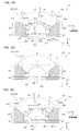
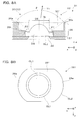
- FIG. 3A and 3B are cross-sectional views for explaining a holding state of the lens base material by the substrate fixed to the first support portion
- FIG. 3C is a view of the lens base material by the substrate fixed to the second support portion. It is sectional drawing explaining a holding state.
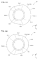
- 4A is a plan view corresponding to FIG. 3A
- FIG. 4B is a plan view corresponding to FIG. 3C. It is a sectional side view explaining the vapor deposition state in each position of a vapor deposition jig. It is a figure explaining the vapor deposition jig
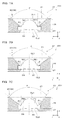
- 7A to 7C are cross-sectional views for explaining the substrate fixed to the vapor deposition jig shown in FIG. 8A and 8B are diagrams for explaining a modification of the lens holding base material.
- the vapor deposition apparatus 100 includes a vapor deposition source 10 that is a film forming material source for vacuum vapor deposition, a substrate 20 that is a holding body that holds a large number of lens bases DS, and a plurality of substrates 20.
- a vapor deposition jig 30 that supports and rotates and reverses, a vacuum container 40 that accommodates the vapor deposition source 10, the vapor deposition jig 30, and the like, a correction plate 50 that adjusts the film thickness in the meridian direction of the vapor deposition jig 30, and a vapor deposition source
- a vapor deposition source controller 91 that controls the operation of 10
- a vapor deposition jig driver 92 that operates and drives the vapor deposition jig 30, an atmospheric pressure controller 93 that controls the atmospheric pressure in the vacuum vessel 40, that is, the degree of vacuum, and the correction plate 50.
- a correction plate control unit 94 that adjusts the arrangement of the vapor deposition source, a vapor deposition source control unit 91, a vapor deposition jig drive unit 92, an atmospheric pressure control unit 93, and a control unit 90 that controls operations of the correction plate control unit 94.
- the lens substrate DS that is the target of film formation by the vapor deposition apparatus 100 is a small plastic lens formed by injection molding using an APEL-based resin material manufactured by Mitsui Chemicals, Inc. The film formation by the vapor deposition apparatus 100 is performed. After processing, it is used as an objective lens of an optical pickup device.
- the vapor deposition source 10 enables vacuum deposition of various film forming materials, and includes a plurality of crucible portions 10 a and an electron gun portion 10 b arranged at the bottom of the vacuum vessel 40.
- the plurality of crucible portions 10a are supported by the turret 10d and can be switched in arrangement.
- Each crucible portion 10a contains an evaporating substance for coating the optical surfaces OL1 and OL2 of the lens substrate DS, and the electron gun portion 10b is in a specific crucible portion 10a arranged at a deposition position by the turret 10d. An electron beam is incident on the evaporated material.
- the evaporation substance in the crucible part 10a can be heated and melted by the electron beam, and the vapor EM of the evaporation substance can be injected upward from the crucible part 10a.
- the vapor deposition source 10 is operated by the vapor deposition source control unit 91.
- the plurality of film forming materials can be coated on the optical surfaces OL1 and OL2 of the lens substrate DS by sequentially moving the plurality of crucible portions 10a to the vapor deposition position, thereby changing the film forming material. By this, a multilayer coating can be formed on the surface of the lens substrate DS.
- the substrate 20 has a rectangular plate-like outer shape, and two-dimensionally arranges a large number of lens base materials DS at the outer edge.
- the substrate 20 is supported by a vapor deposition jig 30 described later as a holder, and is disposed above the vapor deposition source 10 in a state where a large number of lens bases DS face the vapor deposition source 10.
- the substrate (holding body) 20 can be turned upside down or upside down by a vapor deposition jig 30, and as shown in a partially enlarged view, an optical surface that is one surface of each lens substrate DS. Openings 21 and 22 for exposing the surface OL1 and the optical surface OL2 which is the other surface are provided on the front and back sides.
- the vapor EM from the vapor deposition source 10 can be incident on the optical surface OL1 or the optical surface OL2 of the lens substrate DS to deposit the evaporated substance.
- the deposited film that is, the thin film deposited on the optical surfaces OL1 and OL2, for example, is an antireflection film, but can be an optical thin film having various functions such as enhanced reflection and a filter.
- the vapor deposition jig 30 is for appropriately displacing the substrate 20 while supporting the substrate 20 facing the crucible portion 10a disposed at the vapor deposition position in the vapor deposition source 10.
- the vapor deposition jig 30 is disposed above the vapor deposition source 10 in the vacuum container 40.
- the vapor deposition jig 30 has a dome shape or a conical shape as a whole, and as shown in FIGS. 2A, 2B, and 2D, a large number of substrate supports 31 corresponding to a fan-shaped basic region and these substrate supports 31 are arranged. And a support frame 32 that is reversibly supported.
- FIG. 2B shows a state in which the substrate support 31 is being reversed.
- the substrate support 31 is a support that supports a plurality of rectangular plate-shaped substrates 20 that are holding members for the lens base material DS in a state of being arranged adjacent to each other in substantially the same plane.
- each substrate support 31 has a first support portion 33 that has a contour obtained by dividing a dome-shaped region into eight equal parts, and is disposed closer to the center of the dome of the vapor deposition jig 30.
- Two second support portions 34 and 34 disposed near the outer edge of the dome of the vapor deposition jig 30 and a pair of inversion shafts 35 are provided.
- the first support portion 33 extends along the xy plane inherent to the first support portion 33 in a state along the reference axis 31a. Fix it to be parallel to the main surface.
- the second support portions 34 and 34 fix the pair of substrates 20 and 20 to both sides of the reference shaft 31a in the partial area A02 near the outer edge of the dome of the substrate support 31. At this time, the second support portions 34 and 34 fix both the substrates 20 and 20 so as to be parallel to the main surface along the xy plane unique to the first support portion 33.
- the pair of inversion shafts 35 is supported on a support frame 32 described later and is disposed on the reference shaft 31a.
- the first support portion 33 has a substantially fan-shaped outline as shown in FIG. 2D.
- the first support portion 33 is provided with a rectangular opening 33b that exposes both surfaces of the substrate 20 when the substrate 20 is mounted.
- a locking portion 33a is erected on the support plate 31b at the corner of the opening 33b.
- the locking portion 33a as a part of the first support portion 33, removably supports the substrate 20 from the four corners to prevent it from dropping.
- each of the two second support portions 34 has a substantially fan-shaped outline, and is arranged so as to be mirror-image symmetric with respect to the reference axis 31a.
- Each second support portion 34 is provided with a rectangular opening 34b that exposes the surfaces on both sides of the substrate 20 when the substrate 20 is mounted.
- a locking portion 34a is erected on the support plate 31b at the corner of the opening 34b. The locking portion 34a, as a part of the second support portion 34, removably supports the substrate 20 from the four corners to prevent dropping.
- the 1st support body part 33 and the 2nd 2nd support body part 34 which were demonstrated above are integrally formed as a part of the support plate 31b.
- inversion shaft 35 that extends along the axis of symmetry passing through the center of the first support portion 33, and at the center of the outer edge of the support plate 31b, two second The other inversion shaft 35 extending along the axis of symmetry passing between the two support portions 34 is provided.
- the pair of inversion shafts 35 are respectively supported by the support frame 32 and extend along the reference shaft 31a.
- the reversing shaft 35 is rotated around the reference shaft 31a by a reversing mechanism 41 provided in the vacuum vessel 40 shown in FIG. 1 to reverse the substrate support 31 by 180 °.
- the support frame 32 includes a circular outer frame 32a, a center frame 32b, a radially extending meridian frame 32c, and a rotating device 32d (see FIGS. 1 and 2A to 2C).
- the support frame 32 supports the substrate support 31 in a reversible manner around the reference axis 31a, and rotates the substrate support 31 around a spherical rotation axis OX.
- the support frame 32 is driven by a rotating device 32d that operates under the control of the vapor deposition jig driving unit 92, and rotates around a rotation axis OX that extends vertically.
- the plurality of substrate supports 31 supported by the support frame 32 rotate around the rotation axis OX, and as a result, a large number of substrates 20 rotate around the rotation axis OX.
- substrate 20 inclines and is supported by the outer frame 32a and the center frame 32b which oppose.
- the vacuum vessel 40 supports the vapor deposition source 10 at the bottom and the vapor deposition jig 30 at the top in the internal space IS.
- a reversing mechanism 41 that rotates the reversing shaft 35 in order to reverse the substrate support 31 is provided.
- the vacuum vessel 40 is connected to an atmospheric pressure control unit 93 that controls the atmospheric pressure in the vacuum vessel 40. The inside of the vacuum vessel 40 is depressurized or leaked by the atmospheric pressure control unit 93.
- the correction plate 50 is for adjusting the film thickness difference of the substrate support 31 in the meridian direction.
- the correction plate 50 is disposed between the vapor deposition source 10 and the vapor deposition jig 30.
- the posture of the correction plate 50 in the vacuum vessel 40 is controlled by the correction plate control unit 94. By appropriately raising and lowering the correction plate 50, the portion of the substrate support 31 that is behind the correction plate 50 is prevented from being deposited.
- the control unit 90 controls operations of the vapor deposition source control unit 91, the vapor deposition jig driving unit 92, the atmospheric pressure control unit 93, and the correction plate control unit 94.
- FIGS. 3A to 3C show an xz cross section around the opening 21 of the substrate 20 fixed to the first support portion 33
- FIG. 3B shows a yz cross section around the opening 21 shown in FIG. 3A
- FIG. 3C shows an xz cross section around the opening 21 in the substrate 20 fixed to the second support portion 34.
- the + x direction indicates the peripheral side along the substrate support 31
- the ⁇ x direction indicates the center side along the substrate support 31, that is, the rotation axis OX side.
- the XYZ coordinates shown in FIG. 1 are based on the entire vacuum container 40 and the like, whereas the xyz coordinates shown in FIG. 3 and the like are based on individual substrate supports 31.
- the substrate 20 shown in FIG. 3A or the like is fixed to the first support portion 33 side as described above, and is disposed at a position relatively close to the rotation axis OX of the vapor deposition jig 30.
- the substrate 20 includes a first member 26 that holds the lens base DS from the first optical surface OL1 side, and a second member 27 that holds the lens base DS from the second optical surface OL2 side.
- the first member 26 is provided with an opening 21 through which the first optical surface OL1 of the lens substrate DS is exposed.
- the second member 27 is provided with an opening 22 that exposes the second optical surface OL2 of the lens substrate DS.
- the lens base DS is made of plastic and includes a circular optical function part DSa having an optical function and an annular flange part DSb provided radially outward from the outer edge of the optical function part DSa.
- This lens substrate DS becomes an objective lens for an optical pickup device with NA of 0.75 or more by film formation.
- optical information corresponding to a BD (Blu-Ray Disc) standard with a wavelength of 405 nm and NA of 0.85 can be read or written.
- the optical function part DSa has a relatively large convex first optical surface OL1 on one side and a convex second optical surface OL2 having a smaller curvature than the first optical surface OL1 on the other side.
- the first optical surface OL1 is a laser light source for writing (recording) or reading (reproducing) when an objective lens completed by forming a film on the lens substrate DS is incorporated into an optical pickup device and operated. It is arranged on the closer side.
- the second optical surface OL2 is arranged to face the optical information recording medium (specifically, BD) when the objective lens obtained from the lens base DS is incorporated into the optical pickup device and operated. .
- the first optical surface OL1 is a smooth mirror surface, a fine structure or a fine shape which is a diffractive structure can be provided.
- the second optical surface OL2 is a smooth mirror surface having no diffractive structure or the like.
- the lens base DS is for BD
- the thickness on the lens axis in the direction parallel to the lens optical axis OA of the lens base DS is t (mm)
- the focal length of DSa is f (mm)
- the flange portion DSb of the lens base DS has a uniform thickness, and is fitted and fixed in an annular recess 20r formed when the first member 26 and the second member 27 are connected. Yes.
- the opening 21 on the center side near the rotation axis OX of the substrate support 31 or the vapor deposition jig 30 is a first optical surface OL1 having a relatively large protrusion amount in the lens base DS.
- the inner surface 21a is disposed so as to surround the outer periphery.
- the inner surface 21a is an inclined surface that is inclined with respect to the lens optical axis OA, and forms a tapered surface that is recessed in a mortar shape as a whole.
- a region PA11 of the inner surface 21a of the opening 21 on the ⁇ x side, that is, near the rotation axis OX has a relatively large inclination and a relatively large area.
- the area PA12 of the inner surface 21a that is on the + x side, that is, away from the rotation axis OX, has a relatively small inclination and a relatively small area.
- a relatively flat transition region PAT is formed between the region PA11 close to the rotation axis OX and the region PA12 far from the rotation axis OX to continuously connect them. That is, the outline CL1 at the inner side of the opening 21 or the lower end in the figure is circular, but the outline CL2 at the outer side or upper end of the opening 21 is distorted.
- the region PA11 close to the rotation axis OX and the region PA12 far from the rotation axis OX are approximately conical surfaces, but the apexes of both cones are arranged at different positions with respect to the y direction and the x direction. ing.
- the opening angle ⁇ of the opening 21 provided in the first member 26 is in the range of 90 ° ⁇ ⁇ ⁇ 120 ° in both the x direction and the y direction.
- the opening 21 shown in FIG. 3A or the like has an asymmetric shape with respect to the x direction, and the opening angle element ⁇ 1 in the center of the region PA11 close to the rotation axis OX is in the center of the region PA12 far from the rotation axis OX.
- the opening direction T1 of the opening 21 close to the rotation axis OX is inclined to the ⁇ x side.
- the opening angle ⁇ and the opening angle elements ⁇ 1 and ⁇ 2 described above are considered as inclinations with respect to the lens optical axis OA with reference to the outer edge of the optical effective diameter DE of the lens base DS.
- the inner surface 21a of the opening 21 is approximated by a conical side surface, and therefore the direction of the inner surface 21a, that is, the generatrix of the slope, gives the opening angle ⁇ and the opening angle elements ⁇ 1 and ⁇ 2.
- the opening 21 on the peripheral side far from the rotation axis OX of the vapor deposition jig 30 is arranged so as to surround the first optical surface OL1 having a relatively large protrusion amount in the lens base DS. It has an inner surface 121a.
- the inner surface 121a is an inclined surface that is inclined with respect to the lens optical axis OA, and forms a tapered surface that is recessed in a mortar shape as a whole.
- a region PA21 of the inner surface 121a of the opening 21 on the ⁇ x side, that is, near the rotation axis OX has a relatively small inclination and a relatively small area.
- the area PA22 on the inner surface 121a that is on the + x side, that is, away from the rotation axis OX has a relatively large inclination and a relatively large area. That is, the outline CL1 at the inner side of the opening 21 or the lower end in the figure is circular, but the outline CL2 at the outer side or upper end of the opening 21 is distorted.
- the area PA21 close to the rotation axis OX and the area PA22 far from the rotation axis OX are approximately conical surfaces, but the apexes of both cones are arranged at different positions in the y direction and the x direction. ing.
- the opening angle ⁇ of the opening 21 provided in the first member 26 is in the range of 90 ° ⁇ ⁇ ⁇ 120 ° in both the x direction and the y direction.
- the opening 21 provided in the first member 26 has an asymmetric shape with respect to the x direction, and the opening angle element ⁇ 1 in the center of the region PA21 close to the rotation axis OX is in the region PA22 away from the rotation axis OX. It is smaller than the opening angle element ⁇ 2 at the center. That is, the opening direction T2 of the opening 21 away from the rotation axis OX is inclined to the + x side.
- the opening angle ⁇ of the first optical surface OL1 provided in the first member 26 of the substrate 20 is 90 ° to 120 ° at any location.
- an antireflection film or the like is formed on the first optical surface OL1 of the lens substrate DS, it is possible to form a film with a sufficient film thickness even on the optical surface portion having a large peripheral inclination.
- permeability in a final objective lens can be reduced, and the dispersion
- the film thickness of the antireflection film or the like is obtained by multiplying the actual film thickness by the refractive index.
- the circumferential corner regions Ar and Al on the peripheral side of the substrate support 31 have a large inclination with respect to the vapor deposition source 10 and are relatively far away from the vapor deposition source 10.
- the film thickness decreases significantly around the first optical surface OL1, and the peripheral portion (the optical function of the lens substrate DS) where the first optical surface OL1 is formed. There is a tendency that the film thickness of the portion DSa in an annular portion corresponding to the outer edge) is relatively decreased with respect to the film thickness of the central portion.
- the opening angle ⁇ is larger than 120 °, the film thickness tends to relatively increase in a specific direction (for example, the horizontal + y direction or the ⁇ y direction) in the peripheral portion for the first optical surface OL1. . That is, by setting the opening angle ⁇ to 120 ° or less, it is possible to suppress a phenomenon in which transmittance unevenness or coma aberration occurs in the objective lens obtained from the lens substrate DS and the performance of the objective lens deteriorates.
- the incident state of the vapor EM of the evaporating substance evaporating from the crucible portion 10a of the vapor deposition source 10 is different at different positions in the meridian direction of the substrate support 31, that is, in the x direction.
- the substrate support 31 and the vapor deposition jig 30 are fixed, and the crucible portion 10a rotates about the rotation axis OX.
- the elevation angle with respect to the crucible portion 10a varies from ⁇ 0 to ⁇ 0, but the incident angle of the vapor EM viewed from the lens substrate DS1 is kept symmetrical. That is, the vapor EM is incident on the lens base DS1 around the normal line PL of the substrate support 31 in an angle range that does not deviate either in the ⁇ x direction near the rotation axis OX or in the + x direction away from the rotation axis OX. To do.
- the elevation angle with respect to the crucible portion 10a varies from ⁇ + to ⁇ +, and the incident angle of the vapor EM viewed from the lens substrate DS2 is symmetric. Sex is lost and biased. That is, the incident amount of the vapor EM to the lens base material DS2 is relatively reduced from the ⁇ x direction that is close to the rotation axis OX around the normal line PL of the substrate support 31, and the + x direction that is far from the rotation axis OX. The amount of vapor EM incident on the lens substrate DS2 from the lens increases relatively.
- the elevation angle with respect to the crucible portion 10a changes from ⁇ ⁇ to ⁇ ⁇
- the incident angle of the vapor EM viewed from the lens substrate DS3 is Symmetry is lost and biased. That is, the incident amount of the vapor EM to the lens base material DS3 relatively increases from the ⁇ x direction close to the rotation axis OX around the normal line PL of the substrate support 31 to the + x direction far from the rotation axis OX.
- the incident amount of the vapor EM from the lens to the lens base material DS3 relatively decreases.
- Comparing the inner region A2 and the outer region A3 is common in that the amount of incident steam EM changes in the meridian direction, that is, the x direction, and asymmetry occurs, but the direction in which the incident of steam EM increases is reversed. Yes.
- the inner region (first region) A2 is separated from the rotation axis OX by a first distance d1 or less, and the outer region (second region) A3 is a second distance d2 larger than the first distance d1 from the rotation axis OX. It's far away.
- the opening 21 arranged closer to the center near the rotation axis OX has the opening angle element ⁇ 1 at the center of the area PA11 near the rotation axis OX as the rotation axis OX. It has a shape that is larger than the opening angle element ⁇ 2 at the center of the area PA12 away from the area.
- the opening angle elements ⁇ 1 and ⁇ 2 in the ⁇ x directions between the pair of peripheral portions PE1 and PE2 facing each other in the ⁇ x direction in the optical function portion DSa of the lens base DS2 shown in FIG. The film thickness difference can be reduced.
- the opening angle element ⁇ 1 of the opposed region PA11 of the inner surface 21a is relatively increased, and the incident range of the vapor EM is widened, resulting in the vaporized substance.
- the amount of deposition is increased.
- the vapor EM that contributes to the film formation has the most straight component but also has some wraparound component due to scattering. By increasing the opening angle element ⁇ 1, such a wraparound component is deposited. This can contribute to an increase in film thickness.
- the opening angle element ⁇ 2 of the facing area PA12 of the inner surface 21a is relatively reduced to limit the incident range of the vapor EM, and as a result of the evaporated substance. The amount of deposition is reduced.
- the opening 21 on the peripheral side away from the rotation axis OX has an opening angle at the center of the area PA22 where the opening angle element ⁇ 1 at the center of the area PA21 near the rotation axis OX is away from the rotation axis OX.
- the shape is smaller than the element ⁇ 2.
- the opening angle element ⁇ 1 of the opposing area PA21 of the inner surface 121a is relatively reduced to limit the incident range of the steam EM and result in the evaporated substance.
- the amount of deposition is reduced.
- the opening angle element ⁇ 2 of the facing area PA22 of the inner surface 121a is relatively increased to widen the incident range of the vapor EM, and the resultant deposition of the evaporated substance The amount is increased.
- the opening angle elements ⁇ 1 and ⁇ 2 of the opening 21 in accordance with the position in the x direction.
- the substrate 20 it is possible to use a substrate in which openings 21 arranged two-dimensionally with a distribution in which the opening angle elements ⁇ 1 and ⁇ 2 are changed according to the position in the x direction (that is, with different inclinations) are formed.
- the production cost of 20 will be increased. Therefore, the opening 21 formed in the substrate 20 fixed to the first support portion 33 is uniform regardless of location, has the shape shown in FIG. 3A, and is fixed to the second support portion 34.
- the opening 21 formed in the substrate 20 is uniform regardless of location and has the shape shown in FIG. 3C.
- the opening angle ⁇ is 105 °
- the opening angle element ⁇ 1 is 60 ° or 45 °
- the opening angle element ⁇ 2 is 45 ° or 60 °.
- the surface roughness of the inner surfaces 21a and 121a of the opening 21 formed in each part of the substrate 20 is such that Rmax is 6.3 ⁇ m or less.
- Rmax is 6.3 ⁇ m or less.
- the surface roughness of the peripheral surface S22 of the opening 21 is also Rmax of 6.3 ⁇ m or less. Furthermore, it is desirable that the surface roughness of the inner surface S11 and the peripheral surface S12 of the opening 22 on the opposite side is Rmax of 6.3 ⁇ m or less.
- the lens substrate DS is produced by injection molding or the like. Thereafter, the lens base DS is set on the substrate 20. Thereafter, the substrate 20 is attached to the substrate support 31. At this time, each substrate 20 is fixed to the support portions 33 and 34 corresponding to the state of the opening 21 formed in the substrate 20 (specifically, the opening direction).
- the substrate support 31 or the vapor deposition jig 30 to which the lens base material DS is fixed in this way is placed under vacuum in the vacuum vessel 40 and vapor deposition is performed by the vapor EM from the vapor deposition source 10.
- the deposition jig 30 is rotated around the rotation axis OX by the rotating device 32d, thereby improving the uniformity of film formation.
- the substrate support 31 is inverted 180 ° around the reference axis 31a, and the same film formation is performed. Thereby, a thin film can be formed on the second optical surface OL2 in a lump.
- the substrate support 31 and the like are taken out from the vacuum container 40, and the lens base material DS, that is, the objective lens after vapor deposition is taken out from the substrate 20 supported by the substrate support 31.
- the objective lens is completed.
- the opening angle ⁇ of the opening 21 on the first optical surface OL1 side of the substrate 20 that is the holding body is set in a range of 90 ° ⁇ ⁇ ⁇ 120 °. Therefore, at each position on the substrate 20 fixed to the second support portion 34 or the like, an antireflection film having a sufficient film thickness can be formed even in the peripheral portion of the first optical surface OL1, and transmission is possible. The occurrence of spot spots can be prevented.
- the opening 21 on the OL1 side on the first optical surface side of the substrate 20 has an opening angle element ⁇ 1 near the rotation axis OX far from the rotation axis OX.
- the opening angle element ⁇ 2 has a shape that is larger than the opening angle element ⁇ 2.
- the tendency of the film thickness to be reduced on the rotation axis OX side is suppressed, and the film can be formed with a relatively uniform film thickness in the peripheral portion of the first optical surface OL1. Comatic aberration can be reduced.
- the opening 21 on the OL1 side on the first optical surface side of the substrate 20 is far from the rotation axis OX. It has a shape that is smaller than the opening angle element ⁇ 2.
- the objective lens manufacturing method according to the second embodiment of the present invention will be described below.
- the manufacturing method of the second embodiment is a modification of the manufacturing method of the first embodiment, and parts not specifically described are the same as those of the first embodiment.
- FIG. 6 shows a substrate holder 231 incorporated in the vapor deposition apparatus 100 for carrying out the second embodiment, and corresponds to FIG. 2D.
- the substrate holder 231 includes a first support portion 33 disposed near the center of the dome of the vapor deposition jig 30 and two second support portions 34 and 34 disposed near the outer edge of the dome of the vapor deposition jig 30. And two third support portions 39, 39 disposed between them. Similar to the second support portions 34 and 34, the third support portions 39 and 39 are arranged so as to be mirror-image symmetric with respect to the reference axis 31a.
- Each of the third support portions 39 is provided with a rectangular opening 39b that exposes both surfaces of the substrate 20 when the substrate 20 is mounted, and locking portions 39a are provided on the support plate 31b at the four corners of the opening 39b. It is erected.
- the locking portion 39a as a part of the third support portion 39, removably supports the substrate 20 from the four corners to prevent dropping.
- the opening angle ⁇ of the opening 21 on the first optical surface OL1 side is 90 ° ⁇ ⁇
- the opening angle element ⁇ 1 on the ⁇ x side is equal to the opening angle element ⁇ 2 on the + x side, although the range is set to ⁇ 120 °.
- the opening angle ⁇ extends over the entire circumference as in the first embodiment.
- the range of 90 ° ⁇ ⁇ ⁇ 120 ° is established, and the relationship of ⁇ 1> ⁇ 2 holds for the opening angle elements ⁇ 1 and ⁇ 2 in the x direction.
- the opening angle ⁇ extends over the entire circumference as in the first embodiment.
- the range of 90 ° ⁇ ⁇ ⁇ 120 ° is set, and the relationship of ⁇ 1 ⁇ 2 holds for the opening angle elements ⁇ 1 and ⁇ 2 in the x direction.
- the shape of the opening 21 is not limited to a cone and can be various shapes.
- 8A and 8B correspond to FIGS. 3A and 4A and include a stepped opening 321.
- the opening 321 has an opening angle ⁇ and opening angle elements ⁇ 1 and ⁇ 2 defined by the upper edge portion 26e.
- the bottom surface 26f of the step has an oval shape having parallel straight contour portions.
- Such an opening 321 can also control the state of the vapor EM that is incident on the first optical surface OL1 of the lens base DS, and can form a film with less bias on the first optical surface OL1.
- the opening 21 in FIG. 3C can be replaced with a similar step shape.
- the openings 33b, 34b and the like of the substrate support 31 and the like are rectangular, but any shape that can expose the substrate 20 while supporting the substrate 20 is acceptable.
- the lens substrate DS is a plastic lens.
- the material of the lens substrate DS is not limited to plastic, and may be glass or other inorganic materials.
- the vapor deposition source 10 is heated by an electron beam, but the vapor deposition source 10 can be heated by another heating method.
- the locking portions 33a, 34a and the like are provided at the four corners of the openings 33b and 34b.
- the substrate 20 can be stably held, for example, on the sides of the openings 33b and 34b, etc.
- the locking portions 33a, 34a and the like can be provided at the positions.
Landscapes
- Chemical & Material Sciences (AREA)
- Chemical Kinetics & Catalysis (AREA)
- Engineering & Computer Science (AREA)
- Materials Engineering (AREA)
- Mechanical Engineering (AREA)
- Metallurgy (AREA)
- Organic Chemistry (AREA)
- Optical Head (AREA)
- Physical Vapour Deposition (AREA)
- Surface Treatment Of Optical Elements (AREA)
Abstract
支持用平板の位置に関わらず光学面の周辺部で十分な成膜を行うことを目的とする。 保持体である基板20の第1の光学面OL1側の開口21の開き角θが、90°≦θ≦120°の範囲に設定されているので、第2支持体部分34等に固定された基板20上の各位置において、第1の光学面OL1の周辺部でも十分な膜厚を有する反射防止膜を形成することができる。また、回転軸OXに近い第2領域A2では、基板20の第1の光学面側のOL1側の開口21が回転軸OXに近い開き角要素θ1が回転軸OXから遠い開き角要素θ2よりも大きくなるような形状を有しているので、回転軸OX側で膜厚が薄くなる傾向を抑え、第1の光学面OL1の周辺部において比較的一様な膜厚で成膜が可能になり、結果的に得られる対物レンズのコマ収差を低減することができる。
Description
本発明は、レンズ基材に対して蒸着によって成膜を行う光ピックアップ装置用の対物レンズの製造方法に関する。
蒸着装置として、真空容器内に設けたドームに近似する円錐状の蒸着治具によってレンズ基材を支持しつつ円錐を分割した扇状又は台形状の支持用平板単位でレンズ基材を180°反転させ、1バッチの処理でレンズ基材の両面に蒸着を行うものがある(特許文献1参照)。この蒸着装置では、レンズ基材を装着した蒸着治具を鉛直方向に延びる中心軸のまわりに回転させながら蒸着を行う。
一方、有効径の中央部よりも周辺部で反射防止膜の屈折率を相対的に低くした対物レンズが存在する(特許文献2参照)。この対物レンズの製造方法では、基材の外周部と基材保持用の板状部材の突端とを結ぶ線が基材の光軸に対してなす角度の設定を変えることにより、反射防止膜の屈折率を周辺部で低くしている。
しかしながら、特許文献1のような蒸着装置は、回転させる蒸着治具において円錐を分割した支持用平板に沿ってレンズ基材を装着したものであるため、支持用平板の位置によって成膜の状態が異なるという問題がある。また、対物レンズの光学面が大きく突起する場合、対物レンズの光学面の周辺部で十分な成膜を行えなくなるという問題がある。特に、BD(Blu-ray Disc)用の対物レンズは、中央で極めて肉厚になるので、光学面の周辺部で光学面の傾斜が大きくなって周辺部で膜厚が相対的に薄くなる傾向が生じやすい。さらに、同じ対物レンズであっても、例えば支持用平板の緯線方向において、回転軸に近い中心寄りと回転軸から離れた端部寄りとで膜厚差が発生する場合がある。さらに、同じ対物レンズであっても、例えば支持用平板の緯線方向における中心寄りと端部寄りとで膜厚差が発生する場合がある。
以上のような事情は、特許文献2のような対物レンズの製造方法においても同様に生じる。
本発明は、上記背景技術の問題に鑑みてなされたものであり、支持用平板の位置に関わらず光学面の周辺部で十分な成膜を行うことができる光ピックアップ用の対物レンズの製造方法を提供することを目的とする。
上記課題を解決するため、本発明に係る対物レンズの製造方法は、第1の光学面と第1の光学面よりも曲率が小さい第2の光学面とを有し、開口数NAの値が0.75以上の光ピックアップ用の対物レンズの製造方法であって、複数のレンズ基材を保持する保持体を支持する板状の支持体によって複数のレンズ基材を成膜材料源に対向して支持する工程と、成膜材料源に対向する支持体に対して膜材料を被着させる工程とを備え、保持体の第1の光学面側の開口の開き角をθとした場合に、
90°≦θ≦120°
である。なお、本製造方法によって作製される対物レンズは、両凸のレンズであり、例えば、BD(Blu-ray Disc)用の対物レンズであり、一般的には、対物レンズのレンズ光軸に平行な方向のレンズ軸上厚をt(mm)とし、500nm以下の波長の光束における対物レンズの焦点距離をf(mm)としたときに、0.8≦t/f≦2.0となっている。
90°≦θ≦120°
である。なお、本製造方法によって作製される対物レンズは、両凸のレンズであり、例えば、BD(Blu-ray Disc)用の対物レンズであり、一般的には、対物レンズのレンズ光軸に平行な方向のレンズ軸上厚をt(mm)とし、500nm以下の波長の光束における対物レンズの焦点距離をf(mm)としたときに、0.8≦t/f≦2.0となっている。
上記対物レンズの製造方法によれば、保持体の第1の光学面側の開口の開き角θが、90°≦θ≦120°の範囲に設定されているので、保持体を介して支持体上の各位置に配置されたレンズ基材において、光学面の周辺部でも十分な膜厚を有する反射防止膜等を形成することができ、透過率の斑を低減することできる。
本発明の具体的な態様又は側面では、上記製造方法において、保持体が、複数のレンズ基材の第1の光学面側を露出させる開口を有し、当該開口の開き方向が互いに異なる領域を有する。この場合、支持体上の各位置間で膜厚差を低減した成膜が可能になる。
本発明の別の側面では、所定の回転軸から第1距離以下離れている保持体又は支持体の第1の領域において、保持体の第1の光学面側の開口は、所定の回転軸に近い側の開き角要素θ1が所定の回転軸から遠い側の開き角要素θ2よりも大きい形状を有する。この場合、上記所定の回転軸に対して比較的近い側に配置されるレンズ基材について、当該所定の回転軸側で膜厚が薄くなる傾向を抑え、第1の光学面の周辺部においても比較的一様な膜厚で成膜が可能になる。
本発明のさらに別の側面では、所定の回転軸から第1距離以上に設定された第2距離以上離れている保持体又は支持体の第2の領域において、保持体の第1の光学面側の開口は、所定の回転軸に近い側の開き角要素θ1が所定の回転軸から遠い側の開き角要素θ2よりも小さい形状を有する。この場合、上記所定の回転軸に対して比較的遠い側に配置されるレンズ基材について、当該所定の回転軸側で膜厚が厚くなる傾向を抑え、第1の光学面の周辺部においても比較的一様な膜厚で成膜が可能になる。
本発明のさらに別の側面では、支持体が、保持体である複数の基板を支持し、膜材料の被着に際して、所定の回転軸のまわりに回転する。この場合、成膜材料源を支持体に対して相対的に回転させることができ、成膜材料源から射出される膜材料を広い角度範囲でレンズ基材に入射させることができ、成膜の均一性を高めることができる。
本発明のさらに別の側面では、支持体が、所定の回転軸と交差する所定の反転軸のまわりに反転可能であり、支持体に支持された複数の基板が、所定の反転軸に関して回転対称となるような形状及び配列となっている。この場合、複数の基板を180°反転させることで、1バッチの処理でレンズ基材の第1の光学面と第2の光学面とに成膜を行うことができる。
本発明のさらに別の側面では、複数の基板のうち所定の回転軸に近い基板において、第1の光学面側の開口は、所定の回転軸に近い側の開き角要素θ1が所定の回転軸から遠い側の開き角要素θ2よりも大きい形状を有し、複数の基板のうち所定の回転軸から遠い基板において、第1の光学面側の開口は、所定の回転軸に近い側の開き角要素θ1が所定の回転軸から遠い側の開き角要素θ2よりも小さい形状を有する。この場合、複数の基板の位置に応じて適切な成膜が可能になる。
本発明のさらに別の側面では、第1の光学面側の開口が、所定の回転軸を含む面に平行な方向に関して頂点が異なる円錐状の斜面を連結した内面を有する。この場合、開口の表面が円錐面に沿った滑らかなものとなる。
本発明のさらに別の側面では、第1の光学面側の開口が、斜面の母線の方向に対応する開き角を有する。この場合、斜面の母線方向の調整によって開き角を自在に設定することができる。
本発明のさらに別の側面では、第1の光学面側の少なくとも開口に設けた内面の表面粗さに関してRmaxが6.3μm以下である。この場合、開口の内面に膜材料を強く付着させることができ、内面から剥離した膜材料がゴミ等の汚染の原因となることを防止できる。
〔第1実施形態〕
図1等を参照して、本発明の第1実施形態に係る対物レンズの製造方法を実施するための蒸着装置等について説明する。
図1等を参照して、本発明の第1実施形態に係る対物レンズの製造方法を実施するための蒸着装置等について説明する。
図1に示すように、蒸着装置100は、真空蒸着のための成膜材料源である蒸着源10と、多数のレンズ基材DSを保持する保持体である基板20と、複数の基板20を支持して回転及び反転させる蒸着治具30と、蒸着源10や蒸着治具30等を収納する真空容器40と、蒸着治具30の経線方向の膜厚を調節する補正板50と、蒸着源10の動作を制御する蒸着源制御部91と、蒸着治具30を操作駆動する蒸着治具駆動部92と、真空容器40内の気圧すなわち真空度を制御する気圧制御部93と、補正板50の配置を調整する補正板制御部94と、蒸着源制御部91、蒸着治具駆動部92、気圧制御部93、及び補正板制御部94の動作を制御する制御部90とを備える。なお、本蒸着装置100による成膜の対象となるレンズ基材DSは、三井化学社製APELベースの樹脂材料を用いて射出成形により形成された小型のプラスチックレンズであり、蒸着装置100による成膜処理後において光ピックアップ装置の対物レンズとして用いられる。
蒸着源10は、各種成膜材料の真空蒸着を可能にするものであり、真空容器40の底部に配置される複数のルツボ部分10aと電子銃部分10bとを備える。ここで、これら複数のルツボ部分10aは、ターレット10dに支持されて配置の切換が可能になっている。各ルツボ部分10aは、レンズ基材DSの光学面OL1,OL2をコーティングするための蒸発物質を収容しており、電子銃部分10bは、ターレット10dによって蒸着位置に配置された特定のルツボ部分10a中の蒸発物質に対して電子線を入射させる。これにより、電子線でルツボ部分10a中の蒸発物質を加熱して溶かし、ルツボ部分10aから蒸発物質の蒸気EMを上方に射出させることができる。蒸着源10は、蒸着源制御部91によって動作する。なお、複数のルツボ部分10aを蒸着位置に順次移動させて蒸着を行うことにより、複数の成膜材料をレンズ基材DSの光学面OL1,OL2上にコーティングすることができ、成膜材料の変更によってレンズ基材DSの表面に多層のコーティングを形成することができる。
基板20は、矩形の板状の外形を有し、多数のレンズ基材DSを外縁部で保持して2次元的に配置する。基板20は、後述する蒸着治具30に保持体として支持され、多数のレンズ基材DSが蒸着源10に対向するような状態で蒸着源10の上方に配置される。基板(保持体)20は、後に詳述するように蒸着治具30によって上下又は表裏反転可能になっており、一部拡大して示すように、各レンズ基材DSの一方の面である光学面OL1と他方の面である光学面OL2とを露出させる開口21,22を表裏に有している。これら開口21,22により、蒸着源10からの蒸気EMをレンズ基材DSの光学面OL1又は光学面OL2上に入射させ蒸発物質を堆積させることができる。光学面OL1,OL2上に堆積される堆積膜すなわち薄膜は、例えば反射防止膜とするが、増反射、フィルター等の各種機能を有する光学薄膜とすることができる。
蒸着治具30は、基板20を蒸着源10のうち蒸着位置に配置されたルツボ部分10aに対向して支持しつつ適宜変位させるためのものである。蒸着治具30は、真空容器40内で蒸着源10に対向して上方に配置されている。蒸着治具30は、全体としてドーム状又は円錐状であり、図2A、2B、及び2Dに示すように、扇状の基本領域に相当する多数の基板支持体31と、これらの基板支持体31を反転可能に支持する支持枠32とを備える。なお、図2Bでは、基板支持体31が反転途中の状態を示している。基板支持体31は、レンズ基材DS用の保持体である複数の矩形板状の基板20を略同一面内に隣接配置した状態で支持する支持体である。
図2A及び2Dに示すように、各基板支持体31は、ドーム状の領域を8等分した輪郭を有し、蒸着治具30のドーム中央寄りに配置される第1支持体部分33と、蒸着治具30のドーム外縁寄りに配置される2つの第2支持体部分34,34と、一対の反転軸35とを備える。第1支持体部分33は、基板支持体31のドーム中央寄りの部分領域A01において、1つの基板20を、基準軸31aに沿った状態で第1支持体部分33に固有のxy面に沿った主面に平行となるように固定する。第2支持体部分34,34は、基板支持体31のドーム外縁寄りの部分領域A02において、一対の基板20,20を、基準軸31aを挟んだ両側に固定する。この際、第2支持体部分34,34は、両基板20,20を、第1支持体部分33に固有のxy面に沿った主面に平行となるように固定する。一対の反転軸35は、後述する支持枠32に支持されて基準軸31a上に配置される。
第1支持体部分33は、図2Dに示すように、略扇形の輪郭を有している。第1支持体部分33には、基板20を装着した際に基板20の両側の面が露出するような矩形の開口33bが設けられている。開口33bの角部において、支持板31bに係止部33aが立設されている。係止部33aは、第1支持体部分33の一部として、基板20を着脱可能に4隅から支持し落下を防止する。
2つの第2支持体部分34は、図2Dに示すように、略扇形の輪郭をそれぞれ有しており、基準軸31aを挟んで鏡像対称となるように配置されている。各第2支持体部分34には、基板20を装着した際に基板20の両側の面が露出するような矩形の開口34bが設けられている。開口34bの角部において、支持板31bに係止部34aが立設されている。係止部34aは、第2支持体部分34の一部として、基板20を着脱可能に4隅から支持し落下を防止する。
なお、以上で説明した1つの第1支持体部分33と2つの第2支持体部分34とは、支持板31bの一部として一体的に形成されている。
支持板31bの内縁の中央には、第1支持体部分33の中央を通る対称軸に沿って延びる一方の反転軸35が設けられており、支持板31bの外縁の中央には、2つの第2支持体部分34の間を通る対称軸に沿って延びる他方の反転軸35が設けられている。これら一対の反転軸35は、支持枠32にそれぞれ支持されて、基準軸31aに沿って延びている。反転軸35は、図1に示す真空容器40に設けられた反転機構41によって基準軸31aのまわりに回転され、基板支持体31を180°反転させる。
支持枠32は、円形の外枠32aと、中央枠32bと、放射状に延びる経線枠32cと、回転装置32d(図1及び2A~2C参照)とを備える。支持枠32は、基板支持体31を基準軸31aのまわりに反転可能に支持し、基板支持体31を球面の回転軸OXのまわりに回転させるものである。支持枠32は、蒸着治具駆動部92の制御下で動作する回転装置32dに駆動されて鉛直に延びる回転軸OXのまわりに回転する。この支持枠32の回転に伴って、これに支持された複数の基板支持体31が回転軸OXのまわりに回転し、これに伴って多数の基板20が回転軸OXのまわりに回転する。なお、基板20を固定した基板支持体31は、対向する外枠32aと中央枠32bとによって傾斜して支持される。
図1に戻って真空容器40は、その内部空間ISにおいて、蒸着源10を底部に支持し、蒸着治具30を上部に支持する。真空容器40の壁面には、基板支持体31を反転させるために反転軸35を回転させる反転機構41が設けられている。なお、真空容器40には、真空容器40内の気圧を制御する気圧制御部93が接続されている。この気圧制御部93によって真空容器40内を減圧したり、リークしたりする。
補正板50は、基板支持体31の経線方向の膜厚差を調整するためのものである。補正板50は、蒸着源10と蒸着治具30との間に配置されている。補正板50は、補正板制御部94によって、真空容器40内の姿勢が制御されている。補正板50を適宜上げ下ろしすることにより、基板支持体31において、補正板50の陰になる部分は、蒸着がされないようになっている。
制御部90は、蒸着源制御部91、蒸着治具駆動部92、気圧制御部93、及び補正板制御部94の動作を制御する。
以下、図3A~3Cを参照して、基板支持体31に支持された基板(保持体)20によるレンズ基材DSの保持状態について説明する。ここで、図3Aは、第1支持体部分33に固定された基板20のうち開口21周辺のxz断面を示し、図3Bは、図3Aに示す開口21周辺のyz断面を示す。また、図3Cは、第2支持体部分34に固定された基板20のうち開口21周辺のxz断面を示す。以上の図において、+x方向は、基板支持体31に沿った周辺側を示し、-x方向は、基板支持体31に沿った中心側すなわち回転軸OX側を示している。なお、図1に示すXYZ座標は、真空容器40等の全体を基準とするものであるが、図3等に示すxyz座標は、個々の基板支持体31を基準とするものである。
図3A等に示す基板20は、上記のように第1支持体部分33側に固定されており、蒸着治具30の回転軸OXに相対的に近い位置に配置されている。基板20は、レンズ基材DSを第1の光学面OL1側から保持する第1部材26と、レンズ基材DSを第2の光学面OL2側から保持する第2部材27とを有する。第1部材26には、レンズ基材DSの第1光学面OL1を露出させる開口21が設けられている。第2部材27には、レンズ基材DSの第2光学面OL2を露出させる開口22が設けられている。
ここで、レンズ基材DSの形状等について説明する。レンズ基材DSは、プラスチック製で、光学的機能を有する円形の光学機能部DSaと、光学機能部DSaの外縁から半径方向外側に設けられた環状のフランジ部DSbとを備える。このレンズ基材DSは、成膜によって、NA0.75以上の光ピックアップ装置用の対物レンズとなる。具体的には、例えば波長405nmでNA0.85のBD(Blu-Ray Disc)の規格に対応した光情報の読み取り又は書き込みを可能とする。
レンズ基材DSのうち光学機能部DSaは、一方に比較的大きな凸の第1の光学面OL1を有し、他方に第1の光学面OL1よりも曲率の小さな凸の第2の光学面OL2を有する。このうち、第1の光学面OL1は、レンズ基材DSに成膜することで完成した対物レンズを光ピックアップ装置に組み込んで動作させる際に、書き込み(記録)又は読み取り(再生)用のレーザ光源により近い側に配置される。また、第2の光学面OL2は、レンズ基材DSから得た対物レンズを光ピックアップ装置に組み込んで動作させる際に、光情報記録媒体(具体的には、BD)に対向して配置される。第1の光学面OL1は、滑らかな鏡面となっているが、回折構造である微細構造又は微細形状を設けることもできる。一方、第2の光学面OL2は、回折構造等を有しない滑らかな鏡面となっている。
ここで、レンズ基材DSがBD用であることから、レンズ基材DSのレンズ光軸OAに平行な方向のレンズ軸上厚をt(mm)とし、500nm以下の波長の光束における光学機能部DSaの焦点距離をf(mm)としたときに、0.8≦t/f≦2.0となっている。
なお、レンズ基材DSのうちフランジ部DSbは、一様な厚みを有し、第1部材26と第2部材27とを接続した際に形成される環状の窪み20rに嵌め込まれて固定されている。
図3A及び3Bに示すように、基板支持体31又は蒸着治具30の回転軸OXに近い中心側の開口21は、レンズ基材DSのうち相対的に突起量が大きい第1の光学面OL1を囲むように配置された内面21aを有する。この内面21aは、レンズ光軸OAに対して傾斜した傾斜面となっており、全体としてすり鉢状に窪んだテーパー面を形成している。図4Aに示すように、開口21の内面21aのうち-x側すなわち回転軸OXに近い領域PA11は、比較的傾きが大きく比較的面積が広い。一方、内面21aのうち+x側すなわち回転軸OXから離れた領域PA12は、比較的傾きが小さく比較的面積が狭い。また、回転軸OXに近い領域PA11と回転軸OXから離れた領域PA12との間には、これらを連続的に繋ぐ比較的平坦な遷移領域PATが形成されている。つまり、開口21の内側又は図中下端の輪郭CL1は、円形となっているが、開口21の外側又は上端の輪郭CL2は、歪んだ円形となっている。ここで、回転軸OXに近い領域PA11や回転軸OXから遠い領域PA12は、近似的に円錐面となっているが、両者の円錐の頂点は、y方向やx方向に関して互いに異なる位置に配置されている。結果的に、第1部材26に設けた開口21の開き角θは、x方向に関しても、y方向に関しても、90°≦θ≦120°の範囲となっている。ただし、図3A等に示す開口21は、x方向に関して非対称な形状を有しており、回転軸OXに近い領域PA11の中央における開き角要素θ1は、回転軸OXから離れた領域PA12の中央における開き角要素θ2よりも大きくなっている。つまり、回転軸OXに近い開口21は、その開き方向T1が-x側に傾いている。以上の開き角θや開き角要素θ1,θ2は、レンズ基材DSの光学的な有効径DEの外縁を基準として、レンズ光軸OAに対する傾きで考えるものとする。本実施形態の場合、開口21の内面21aが円錐側面で近似されるので、内面21aすなわち斜面の母線の方向が開き角θや開き角要素θ1,θ2を与えることになる。
図3Cに示すように、蒸着治具30の回転軸OXから遠い周辺側の開口21は、レンズ基材DSのうち相対的に突起量が大きい第1の光学面OL1を囲むように配置された内面121aを有する。この内面121aは、レンズ光軸OAに対して傾斜した傾斜面となっており、全体としてすり鉢状に窪んだテーパー面を形成している。図4Bに示すように、開口21の内面121aのうち-x側すなわち回転軸OXに近い領域PA21は、比較的傾きが小さく比較的面積が狭い。一方、内面121aのうち+x側すなわち回転軸OXから離れた領域PA22は、比較的傾きが大きく比較的面積が広い。つまり、開口21の内側又は図中下端の輪郭CL1は、円形となっているが、開口21の外側又は上端の輪郭CL2は、歪んだ円形となっている。ここで、回転軸OXに近い領域PA21や回転軸OXから遠い領域PA22は、近似的に円錐面となっているが、両者の円錐の頂点は、y方向やx方向に関して互いに異なる位置に配置されている。結果的に、第1部材26に設けた開口21の開き角θは、x方向に関しても、y方向に関しても、90°≦θ≦120°の範囲となっている。ただし、第1部材26に設けた開口21は、x方向に関して非対称な形状を有しており、回転軸OXに近い領域PA21の中央における開き角要素θ1は、回転軸OXから離れた領域PA22の中央における開き角要素θ2よりも小さくなっている。つまり、回転軸OXから離れた開口21は、その開き方向T2が+x側に傾いている。
以上のように、基板20の第1部材26に設けた第1の光学面OL1用の開口21は、どの場所でも開き角θが90°~120°となっている。これにより、レンズ基材DSの第1の光学面OL1に反射防止膜等を成膜する際に、周辺の傾きが大きな光学面部分についても、十分な膜厚で成膜を行うことができる。これにより、最終的な対物レンズにおける透過率の斑を低減でき、反射防止膜等のxz断面やyz断面における膜厚のばらつきを減少させることができる。ここで、反射防止膜等の膜厚とは、現実の膜厚に屈折率をかけたものとする。特に、図2Dに示すように、基板支持体31の周辺側の周方向の隅領域Ar,Alは、蒸着源10に対する傾きが大きく蒸着源10から相対的に遠く離れるので、開き角θを上記のように制限することで、レンズ基材DSの第1の光学面OL1上に形成される反射防止膜等のy方向やx方向における膜厚差を少なくすることができる。なお、開き角θが90°より小さいと、第1の光学面OL1の周辺での膜厚減少が顕著になり、第1の光学面OL1が形成される周辺部(レンズ基材DSの光学機能部DSaのうち外縁に対応する環状の部分)の膜厚が中央部の膜厚に対して相対的に減少する傾向が生じる。一方、開き角θが120°より大きいと、第1の光学面OL1用の周辺部のうち特定の方位(例えば横の+y方向又は-y方向)において膜厚が相対的に増加する傾向が生じる。つまり、開き角θを120°以下とすることで、レンズ基材DSから得た対物レンズにおいて透過率斑やコマ収差が発生し、対物レンズの性能が劣化するといた現象を抑制できる。
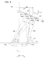
以下、図5を参照して、開口21をx方向に関して非対称とする理由について説明する。図示のように、基板支持体31の経線方向すなわちx方向の異なる位置では、蒸着源10のルツボ部分10aから蒸発する蒸発物質の蒸気EMの入射状態が異なる。ここでは、説明の便宜のため、基板支持体31や蒸着治具30が固定され、ルツボ部分10aが回転軸OXのまわりに回転しているものと考える。中央の基本領域A1では、ルツボ部分10aに対する仰角はβ0からα0まで変化するが、レンズ基材DS1から見た蒸気EMの入射角度は、対称性が保たれたものとなっている。つまり、基板支持体31の法線PLを中心として、回転軸OXに近くなる-x方向と回転軸OXから離れる+x方向とのいずれにも偏らない角度範囲でレンズ基材DS1に蒸気EMが入射する。
しかしながら、回転軸OXに比較的近い内側領域(第1の領域)A2では、ルツボ部分10aに対する仰角はβ+からα+まで変化し、レンズ基材DS2から見た蒸気EMの入射角度は、対称性が失われ偏ったものとなっている。つまり、基板支持体31の法線PLを中心として、回転軸OXに近くなる-x方向からレンズ基材DS2への蒸気EMの入射量が相対的に減少し、回転軸OXから遠くなる+x方向からレンズ基材DS2への蒸気EMの入射量が相対的に増加する。一方、回転軸OXから比較的離れた外側領域(第2の領域)A3でも、ルツボ部分10aに対する仰角はβ-からα-まで変化し、レンズ基材DS3から見た蒸気EMの入射角度は、対称性が失われ偏ったものとなっている。つまり、基板支持体31の法線PLを中心として、回転軸OXに近くなる-x方向からレンズ基材DS3への蒸気EMの入射量が相対的に増加し、回転軸OXから遠くなる+x方向からレンズ基材DS3への蒸気EMの入射量が相対的に減少する。内側領域A2と外側領域A3とを比較すると、経線方向すなわちx方向に蒸気EMの入射量が変化して非対称が生じている点で共通するが、蒸気EMの入射が多くなる方位が逆転している。なお、内側領域(第1の領域)A2は、回転軸OXから第1距離d1以下離れ、外側領域(第2の領域)A3は、回転軸OXから第1距離d1よりも大きい第2距離d2以上離れている。
以上の事情を考慮して、図3A及び4Aに示すように、回転軸OXに近い中心寄りに配置される開口21は、回転軸OXに近い領域PA11の中央における開き角要素θ1が回転軸OXから離れた領域PA12の中央における開き角要素θ2よりも大きくなるような形状を有している。このように、±x方向における開き角要素θ1,θ2に差を設けることで、図5に示すレンズ基材DS2の光学機能部DSaのうち±x方向における対向する一対の周辺部PE1,PE2間の膜厚差を低減することができる。つまり、蒸気EMの入射量が少なくなる周辺部PE1については、内面21aの対向する領域PA11の開き角要素θ1を相対的に大きくして、蒸気EMの入射範囲を広げて蒸発物質の結果的な堆積量を多くしている。なお、成膜(蒸着物質の堆積)に寄与する蒸気EMは、直進成分が最も多いが散乱による回り込み成分もある程度存在し、開き角要素θ1を大きくすることで、このような回り込み成分を堆積させ膜厚増加に寄与させることができる。一方、蒸気EMの入射量が多くなる周辺部PE2については、内面21aの対向する領域PA12の開き角要素θ2を相対的に小さくして、蒸気EMの入射範囲を制限し蒸発物質の結果的な堆積量を少なくしている。
また、図3Cに示すように、回転軸OXから離れた周辺側の開口21は、回転軸OXに近い領域PA21の中央における開き角要素θ1が回転軸OXから離れた領域PA22の中央における開き角要素θ2よりも小さくなるような形状を有している。このように、±x方向における開き角要素θ1,θ2に差を設けることで、図5に示すレンズ基材DS3のx方向における対向する周辺部PE1,PE2間の膜厚差を低減することができる。つまり、蒸気EMの入射量が多くなる周辺部PE1については、内面121aの対向する領域PA21の開き角要素θ1を相対的に小さくして、蒸気EMの入射範囲を制限し蒸発物質の結果的な堆積量を少なくしている。一方、蒸気EMの入射量が少なくなる周辺部PE2について、内面121aの対向する領域PA22の開き角要素θ2を相対的に大きくして、蒸気EMの入射範囲を広げて蒸発物質の結果的な堆積量を多くしている。
蒸気EMの入射量を考慮すると、x方向の位置に応じて開口21の開き角要素θ1,θ2を徐々に変化させることが望ましい。しかしながら、基板20として、x方向の位置に応じて開き角要素θ1,θ2を変化させた(すなわち傾きの異なる)分布で2次元的に配置される開口21を形成したものを用いることは、基板20の作製コストを増加させることになる。よって、第1支持体部分33に固定される基板20に形成される開口21は、場所によらず一様で、図3Aに示す形状を有するものとし、第2支持体部分34に固定される基板20に形成される開口21は、場所によらず一様で、図3Cに示す形状を有するものとする。このように、2段階で開き角要素θ1,θ2を調整するだけでも、x方向に膜厚差が生じることを抑制できコマ収差の発生を低減できた。具体的な作製例では、開き角θを105°、開き角要素θ1を60°又は45°、開き角要素θ2を45°又は60°とした。この条件でレンズ基材DS2,DS3に成膜した後の対物レンズにおいて、周辺部に向けて半径の6割から10割の像高領域でのコート特性を位相ずれ10°以内となるような精度に収めることができた。
基板20の各部に形成する開口21の内面21a,121aの表面粗さは、Rmaxが6.3μm以下のものとなっている。このように、表面粗さを一定以下の比較的滑らかなものとすることで、内面21a,121aから膜材料が剥離すること防止できる。つまり、内面21a,121aから剥離した膜材料によって真空容器40内に細かな粒子が溜まって汚染の原因となることを抑制できる。また、蒸着処理後の搬送及び出荷に際して、コート剥離によるレンズへの汚染(コートゴミ)を防止できる。なお、膜材料の剥離による弊害を防止するためには、開口21の周辺面S22の表面粗さも、Rmaxが6.3μm以下となるようにすることが望ましい。さらに、反対側の開口22の内面S11や周辺面S12の表面粗さも、Rmaxが6.3μm以下となるようにすることが望ましい。
図1の蒸着装置100を用いた対物レンズの製造方法の概要について説明する。まず、射出成形等によってレンズ基材DSを作製する。その後、レンズ基材DSを基板20にセットする。その後、基板20を基板支持体31に取り付ける。この際、各基板20をこれに形成された開口21の状態(具体的には開口方向)に対応する支持体部分33,34に固定する。このようにレンズ基材DSを固定した基板支持体31又は蒸着治具30は、真空容器40内で真空下におかれ、蒸着源10からの蒸気EMによって蒸着が行われる。この際、蒸着治具30が回転装置32dによって回転軸OXのまわりに回転することで、成膜の均一性を高める。一定時間後、第1の光学面OL1上への薄膜の成膜が完了した段階で、基板支持体31を基準軸31aのまわりに180°反転させ、同様の成膜を行う。これにより、第2の光学面OL2上への薄膜の成膜も一括して行うことができる。その後、真空容器40内から基板支持体31等を搬出し、基板支持体31に支持された基板20から蒸着後のレンズ基材DSすなわち対物レンズを取り出す。以上により、対物レンズが完成する。
以上のように、本実施形態の製造方法によれば、保持体である基板20の第1の光学面OL1側の開口21の開き角θが、90°≦θ≦120°の範囲に設定されているので、第2支持体部分34等に固定された基板20上の各位置において、第1の光学面OL1の周辺部でも十分な膜厚を有する反射防止膜を形成することができ、透過率斑の発生を防止できる。また、回転軸OXに近い第1の領域である内側領域A2では、基板20の第1の光学面側のOL1側の開口21が、回転軸OXに近い開き角要素θ1が回転軸OXから遠い開き角要素θ2よりも大きくなるような形状を有している。これにより、回転軸OX側で膜厚が薄くなる傾向を抑え、第1の光学面OL1の周辺部において比較的一様な膜厚で成膜が可能になり、結果的に得られる対物レンズのコマ収差を低減することができる。一方、回転軸OXから遠い第2の領域である外側領域A3では、基板20の第1の光学面側のOL1側の開口21が、回転軸OXに近い開き角要素θ1が回転軸OXから遠い開き角要素θ2よりも小さくなるような形状を有している。これにより、回転軸OX側で膜厚が厚くなる傾向を抑え、第1の光学面OL1の周辺部において比較的一様な膜厚で成膜が可能になり、結果的に得られる対物レンズのコマ収差を低減することができる。
〔第2実施形態〕
以下、本発明の第2実施形態に係る対物レンズの製造方法について説明する。第2実施形態の製造方法は、第1実施形態の製造方法を変形したものであり、特に説明しない部分は、第1実施形態と同様である。
以下、本発明の第2実施形態に係る対物レンズの製造方法について説明する。第2実施形態の製造方法は、第1実施形態の製造方法を変形したものであり、特に説明しない部分は、第1実施形態と同様である。
図6は、第2実施形態を実施するための蒸着装置100に組み込まれる基板ホルダー231を示しており、図2Dに対応するものとなっている。この場合、基板ホルダー231は、蒸着治具30のドーム中央寄りに配置される第1支持体部分33と、蒸着治具30のドーム外縁寄りに配置される2つの第2支持体部分34,34と、これらの中間に配置される2つの第3支持体部分39,39とを備える。第3支持体部分39,39は、第2支持体部分34,34と同様に、基準軸31aを挟んで鏡像対称となるように配置されている。各第3支持体部分39には、基板20を装着した際に基板20の両側の面が露出するような矩形の開口39bが設けられ、開口39bの四隅において支持板31bに係止部39aが立設されている。係止部39aは、第3支持体部分39の一部として、基板20を着脱可能に4隅から支持し落下を防止する。
図7Aに示すように、第3支持体部分39に支持される基板20(具体的には基板20A)の場合、第1の光学面OL1側の開口21の開き角θは、90°≦θ≦120°の範囲に設定されているが、-x側の開き角要素θ1と+x側の開き角要素θ2が等しくなっている。これは、図5の内側領域A1に対応させたものであり、ルツボ部分10aからの蒸気EMの入射角度に殆ど偏りがないことを考慮して、開口21の開き方向を基板20の法線方向すなわちz方向としている。
なお、図7Bに示すように、第1支持体部分33に支持される基板20(具体的には基板20B)の場合、第1実施形態の場合と同様に、開き角θが全周に亘って90°≦θ≦120°の範囲に設定され、x方向の開き角要素θ1,θ2についてθ1>θ2の関係が成り立っている。
また、図7Cに示すように、第2支持体部分34に支持される基板20(具体的には基板20C)の場合、第1実施形態の場合と同様に、開き角θが全周に亘って90°≦θ≦120°の範囲に設定され、x方向の開き角要素θ1,θ2についてθ1<θ2の関係が成り立っている。
以上実施形態に即して本発明を説明したが、本発明は、上記実施形態に限定されるものではなく、様々な変形が可能である。
例えば、開口21の形状は、開き角θや開き角要素θ1,θ2を規定できれば、円錐に限らず様々な形状とできる。図8A及び8Bは、図3A及び4Aに対応するものであり、段差状の開口321を備える。この開口321は、上端のエッジ部26eで規定される開き角θや開き角要素θ1,θ2を有するものとなっている。なお、段差の底面26fは、平行な直線輪郭部を有する長円形となっている。このような開口321によっても、レンズ基材DSの第1の光学面OL1に入射する蒸気EMの状態を制御することができ、第1の光学面OL1上に偏りの少ない成膜が可能になる。なお、図示を省略したが、図3Cの開口21も同様の段差形状に置き換えることができる。
また、上記実施形態では、基板支持体31等の開口33b,34b等を矩形としたが、基板20を支持しつつ、基板20を露出可能な形状であればよい。
また、上記実施形態では、レンズ基材DSがプラスチック製のレンズであるとしたが、レンズ基材DSの材料は、プラスチックに限らずガラスその他の無機材料とすることもできる。
また、上記実施形態では、蒸着源10を電子線で加熱するが、他の加熱法で蒸着源10を加熱することもできる。
また、上記実施形態では、開口33b,34b等の4隅に係止部33a,34a等を設けたが、基板20を安定して保持できれば、例えば開口33b,34b等の辺上等、適当な位置に係止部33a,34a等を設けることができる。
Claims (10)
- 第1の光学面と前記第1の光学面よりも曲率が小さい第2の光学面とを有し、開口数NAの値が0.75以上の光ピックアップ用の対物レンズの製造方法であって、
複数のレンズ基材を保持する保持体を支持する板状の支持体によって前記複数のレンズ基材を成膜材料源に対向して支持する工程と、
前記成膜材料源に対向する前記支持体に対して膜材料を被着させる工程と、
を備え、
前記保持体の前記第1の光学面側の開口の開き角をθとした場合に、
90°≦θ≦120°
である対物レンズの製造方法。 - 前記保持体は、前記複数のレンズ基材の前記第1の光学面側を露出させる開口を有し、当該開口の開き方向が互いに異なる領域を有する、請求項1に記載の対物レンズの製造方法。
- 所定の回転軸から第1距離以下離れている前記保持体の第1の領域において、前記保持体の前記第1の光学面側の開口は、前記所定の回転軸に近い側の開き角要素θ1が前記所定の回転軸から遠い側の開き角要素θ2よりも大きい形状を有する、請求項2に記載の対物レンズの製造方法。
- 所定の回転軸から前記第1距離以上に設定された第2距離以上離れている前記保持体の第2の領域において、前記保持体の前記第1の光学面側の開口は、前記所定の回転軸に近い側の開き角要素θ1が前記所定の回転軸から遠い側の開き角要素θ2よりも小さい形状を有する、請求項2に記載の対物レンズの製造方法。
- 前記支持体は、前記保持体である複数の基板を支持し、膜材料の被着に際して、所定の回転軸のまわりに回転する、請求項1に記載の対物レンズの製造方法。
- 前記支持体は、前記所定の回転軸と交差する所定の反転軸のまわりに反転可能であり、
前記支持体に支持された前記複数の基板は、前記所定の反転軸に関して回転対称となるような形状及び配列となっている、請求項5に記載の対物レンズの製造方法。 - 前記複数の基板のうち前記所定の回転軸に近い基板において、前記第1の光学面側の開口は、前記所定の回転軸に近い側の開き角要素θ1が前記所定の回転軸から遠い側の開き角要素θ2よりも大きい形状を有し、前記複数の基板のうち前記所定の回転軸から遠い基板において、前記第1の光学面側の開口は、前記所定の回転軸に近い側の開き角要素θ1が前記所定の回転軸から遠い側の開き角要素θ2よりも小さい形状を有する、請求項5に記載の対物レンズの製造方法。
- 前記第1の光学面側の開口は、前記所定の回転軸を含む面に平行な方向に関して頂点が異なる円錐状の斜面を連結した内面を有する、請求項1に記載の対物レンズの製造方法。
- 前記第1の光学面側の開口は、斜面の母線の方向に対応する開き角を有する、請求項8に記載の対物レンズの製造方法。
- 前記第1の光学面側の少なくとも開口に設けた内面の表面粗さに関してRmaxが6.3μm以下である、請求項1に記載の対物レンズの製造方法。
Priority Applications (1)
| Application Number | Priority Date | Filing Date | Title |
|---|---|---|---|
| JP2013507643A JPWO2012133468A1 (ja) | 2011-03-28 | 2012-03-27 | 対物レンズの製造方法 |
Applications Claiming Priority (2)
| Application Number | Priority Date | Filing Date | Title |
|---|---|---|---|
| JP2011-070986 | 2011-03-28 | ||
| JP2011070986 | 2011-03-28 |
Publications (1)
| Publication Number | Publication Date |
|---|---|
| WO2012133468A1 true WO2012133468A1 (ja) | 2012-10-04 |
Family
ID=46931180
Family Applications (1)
| Application Number | Title | Priority Date | Filing Date |
|---|---|---|---|
| PCT/JP2012/058024 Ceased WO2012133468A1 (ja) | 2011-03-28 | 2012-03-27 | 対物レンズの製造方法 |
Country Status (2)
| Country | Link |
|---|---|
| JP (1) | JPWO2012133468A1 (ja) |
| WO (1) | WO2012133468A1 (ja) |
Cited By (2)
| Publication number | Priority date | Publication date | Assignee | Title |
|---|---|---|---|---|
| JP2013256707A (ja) * | 2012-06-14 | 2013-12-26 | Canon Inc | 成膜装置 |
| JP2016169424A (ja) * | 2015-03-13 | 2016-09-23 | コニカミノルタ株式会社 | 膜厚傾斜膜の製造装置および製造方法 |
Citations (3)
| Publication number | Priority date | Publication date | Assignee | Title |
|---|---|---|---|---|
| JP2001348080A (ja) * | 2000-04-04 | 2001-12-18 | Nissin Kohki Co Ltd | 製品収納容器 |
| JP2008009117A (ja) * | 2006-06-29 | 2008-01-17 | Konica Minolta Opto Inc | 誘電体多層膜の製造方法 |
| JP2011053573A (ja) * | 2009-09-04 | 2011-03-17 | Konica Minolta Opto Inc | 薄膜形成方法 |
-
2012
- 2012-03-27 JP JP2013507643A patent/JPWO2012133468A1/ja active Pending
- 2012-03-27 WO PCT/JP2012/058024 patent/WO2012133468A1/ja not_active Ceased
Patent Citations (3)
| Publication number | Priority date | Publication date | Assignee | Title |
|---|---|---|---|---|
| JP2001348080A (ja) * | 2000-04-04 | 2001-12-18 | Nissin Kohki Co Ltd | 製品収納容器 |
| JP2008009117A (ja) * | 2006-06-29 | 2008-01-17 | Konica Minolta Opto Inc | 誘電体多層膜の製造方法 |
| JP2011053573A (ja) * | 2009-09-04 | 2011-03-17 | Konica Minolta Opto Inc | 薄膜形成方法 |
Cited By (2)
| Publication number | Priority date | Publication date | Assignee | Title |
|---|---|---|---|---|
| JP2013256707A (ja) * | 2012-06-14 | 2013-12-26 | Canon Inc | 成膜装置 |
| JP2016169424A (ja) * | 2015-03-13 | 2016-09-23 | コニカミノルタ株式会社 | 膜厚傾斜膜の製造装置および製造方法 |
Also Published As
| Publication number | Publication date |
|---|---|
| JPWO2012133468A1 (ja) | 2014-07-28 |
Similar Documents
| Publication | Publication Date | Title |
|---|---|---|
| US6320699B1 (en) | Aberration correcting apparatus and optical apparatus using the same | |
| CN100412570C (zh) | 光学透镜及光信息记录再生装置 | |
| US6994808B2 (en) | Planar lens and method for fabricating the same | |
| CN100354673C (zh) | 将光学镜片底料设定于支座上的机构 | |
| WO2012133468A1 (ja) | 対物レンズの製造方法 | |
| EP0987575A2 (en) | Scanning optical device | |
| JP4128450B2 (ja) | 光情報媒体 | |
| CN118363167A (zh) | 一种可调球差校正系统及光学变焦系统 | |
| JP4342087B2 (ja) | 光情報媒体の製造方法および製造装置 | |
| JP2009098644A (ja) | 液晶フレネルレンズ及び液晶フレネルレンズの製造装置 | |
| CN100480774C (zh) | 提供可变折射表面的光学像差校正元件及其制造方法 | |
| TWI486620B (zh) | 光學構件的製造方法及光學構件 | |
| JP2006241588A (ja) | グラジエント式光学薄膜形成装置及びその治具 | |
| CN100478488C (zh) | 渐变式光学薄膜镀制装置及其治工具套环 | |
| JPH0416763B2 (ja) | ||
| JP5654255B2 (ja) | 蒸着装置 | |
| JP6714399B2 (ja) | 光学素子及び光学薄膜の成膜方法 | |
| WO2013115113A1 (ja) | 光ピックアップ装置用の対物レンズの製造方法、対物レンズ及び対物レンズの検査方法 | |
| US20170212281A1 (en) | Method for manufacturing microarray lens | |
| JP2011231370A (ja) | 蒸着治具、蒸着装置、及び対物レンズの製造方法 | |
| JP2024115831A (ja) | 成膜装置 | |
| JP2000348373A (ja) | 光ピックアップ装置及び光ピックアップ装置の調整法 | |
| CN100434964C (zh) | 激光扫描装置的fθ镜片的制法 | |
| US20240101473A1 (en) | Method for manufacturing glass plate, method for manufacturing glass substrate for magnetic disk, method for manufacturing magnetic disk, and apparatus for processing glass plate | |
| KR101960599B1 (ko) | 진공증착에 의한 무반사코팅층이 형성된 cctv 돔렌즈 및 그 제작방법 |
Legal Events
| Date | Code | Title | Description |
|---|---|---|---|
| 121 | Ep: the epo has been informed by wipo that ep was designated in this application |
Ref document number: 12765652 Country of ref document: EP Kind code of ref document: A1 |
|
| ENP | Entry into the national phase |
Ref document number: 2013507643 Country of ref document: JP Kind code of ref document: A |
|
| NENP | Non-entry into the national phase |
Ref country code: DE |
|
| 122 | Ep: pct application non-entry in european phase |
Ref document number: 12765652 Country of ref document: EP Kind code of ref document: A1 |