WO2012133133A1 - Receiver device and receiver method - Google Patents
Receiver device and receiver method Download PDFInfo
- Publication number
- WO2012133133A1 WO2012133133A1 PCT/JP2012/057423 JP2012057423W WO2012133133A1 WO 2012133133 A1 WO2012133133 A1 WO 2012133133A1 JP 2012057423 W JP2012057423 W JP 2012057423W WO 2012133133 A1 WO2012133133 A1 WO 2012133133A1
- Authority
- WO
- WIPO (PCT)
- Prior art keywords
- frequency
- signal
- processing unit
- frequency processing
- output
- Prior art date
Links
Images


Classifications
-
- H—ELECTRICITY
- H04—ELECTRIC COMMUNICATION TECHNIQUE
- H04N—PICTORIAL COMMUNICATION, e.g. TELEVISION
- H04N5/00—Details of television systems
- H04N5/44—Receiver circuitry for the reception of television signals according to analogue transmission standards
-
- H—ELECTRICITY
- H04—ELECTRIC COMMUNICATION TECHNIQUE
- H04H—BROADCAST COMMUNICATION
- H04H40/00—Arrangements specially adapted for receiving broadcast information
- H04H40/18—Arrangements characterised by circuits or components specially adapted for receiving
-
- H—ELECTRICITY
- H04—ELECTRIC COMMUNICATION TECHNIQUE
- H04H—BROADCAST COMMUNICATION
- H04H20/00—Arrangements for broadcast or for distribution combined with broadcast
- H04H20/26—Arrangements for switching distribution systems
-
- H—ELECTRICITY
- H04—ELECTRIC COMMUNICATION TECHNIQUE
- H04H—BROADCAST COMMUNICATION
- H04H40/00—Arrangements specially adapted for receiving broadcast information
- H04H40/18—Arrangements characterised by circuits or components specially adapted for receiving
- H04H40/27—Arrangements characterised by circuits or components specially adapted for receiving specially adapted for broadcast systems covered by groups H04H20/53 - H04H20/95
- H04H40/90—Arrangements characterised by circuits or components specially adapted for receiving specially adapted for broadcast systems covered by groups H04H20/53 - H04H20/95 specially adapted for satellite broadcast receiving
-
- H—ELECTRICITY
- H04—ELECTRIC COMMUNICATION TECHNIQUE
- H04N—PICTORIAL COMMUNICATION, e.g. TELEVISION
- H04N21/00—Selective content distribution, e.g. interactive television or video on demand [VOD]
- H04N21/40—Client devices specifically adapted for the reception of or interaction with content, e.g. set-top-box [STB]; Operations thereof
- H04N21/41—Structure of client; Structure of client peripherals
- H04N21/426—Internal components of the client ; Characteristics thereof
- H04N21/42607—Internal components of the client ; Characteristics thereof for processing the incoming bitstream
- H04N21/4263—Internal components of the client ; Characteristics thereof for processing the incoming bitstream involving specific tuning arrangements, e.g. two tuners
-
- H—ELECTRICITY
- H04—ELECTRIC COMMUNICATION TECHNIQUE
- H04N—PICTORIAL COMMUNICATION, e.g. TELEVISION
- H04N21/00—Selective content distribution, e.g. interactive television or video on demand [VOD]
- H04N21/40—Client devices specifically adapted for the reception of or interaction with content, e.g. set-top-box [STB]; Operations thereof
- H04N21/43—Processing of content or additional data, e.g. demultiplexing additional data from a digital video stream; Elementary client operations, e.g. monitoring of home network or synchronising decoder's clock; Client middleware
- H04N21/438—Interfacing the downstream path of the transmission network originating from a server, e.g. retrieving MPEG packets from an IP network
- H04N21/4382—Demodulation or channel decoding, e.g. QPSK demodulation
-
- H—ELECTRICITY
- H04—ELECTRIC COMMUNICATION TECHNIQUE
- H04N—PICTORIAL COMMUNICATION, e.g. TELEVISION
- H04N21/00—Selective content distribution, e.g. interactive television or video on demand [VOD]
- H04N21/40—Client devices specifically adapted for the reception of or interaction with content, e.g. set-top-box [STB]; Operations thereof
- H04N21/45—Management operations performed by the client for facilitating the reception of or the interaction with the content or administrating data related to the end-user or to the client device itself, e.g. learning user preferences for recommending movies, resolving scheduling conflicts
- H04N21/462—Content or additional data management, e.g. creating a master electronic program guide from data received from the Internet and a Head-end, controlling the complexity of a video stream by scaling the resolution or bit-rate based on the client capabilities
- H04N21/4622—Retrieving content or additional data from different sources, e.g. from a broadcast channel and the Internet
-
- H—ELECTRICITY
- H04—ELECTRIC COMMUNICATION TECHNIQUE
- H04N—PICTORIAL COMMUNICATION, e.g. TELEVISION
- H04N21/00—Selective content distribution, e.g. interactive television or video on demand [VOD]
- H04N21/60—Network structure or processes for video distribution between server and client or between remote clients; Control signalling between clients, server and network components; Transmission of management data between server and client, e.g. sending from server to client commands for recording incoming content stream; Communication details between server and client
- H04N21/61—Network physical structure; Signal processing
- H04N21/6106—Network physical structure; Signal processing specially adapted to the downstream path of the transmission network
- H04N21/6112—Network physical structure; Signal processing specially adapted to the downstream path of the transmission network involving terrestrial transmission, e.g. DVB-T
-
- H—ELECTRICITY
- H04—ELECTRIC COMMUNICATION TECHNIQUE
- H04N—PICTORIAL COMMUNICATION, e.g. TELEVISION
- H04N21/00—Selective content distribution, e.g. interactive television or video on demand [VOD]
- H04N21/60—Network structure or processes for video distribution between server and client or between remote clients; Control signalling between clients, server and network components; Transmission of management data between server and client, e.g. sending from server to client commands for recording incoming content stream; Communication details between server and client
- H04N21/61—Network physical structure; Signal processing
- H04N21/6106—Network physical structure; Signal processing specially adapted to the downstream path of the transmission network
- H04N21/6143—Network physical structure; Signal processing specially adapted to the downstream path of the transmission network involving transmission via a satellite
-
- H—ELECTRICITY
- H04—ELECTRIC COMMUNICATION TECHNIQUE
- H04N—PICTORIAL COMMUNICATION, e.g. TELEVISION
- H04N5/00—Details of television systems
- H04N5/44—Receiver circuitry for the reception of television signals according to analogue transmission standards
- H04N5/455—Demodulation-circuits
-
- H—ELECTRICITY
- H04—ELECTRIC COMMUNICATION TECHNIQUE
- H04N—PICTORIAL COMMUNICATION, e.g. TELEVISION
- H04N5/00—Details of television systems
- H04N5/44—Receiver circuitry for the reception of television signals according to analogue transmission standards
- H04N5/46—Receiver circuitry for the reception of television signals according to analogue transmission standards for receiving on more than one standard at will
Definitions
- the present disclosure relates to a receiving device that receives broadcast waves and a receiving method using the receiving device, and more particularly, to a technology that receives a plurality of broadcast waves having different frequency bands.
- each broadcast receiving tuner unit is configured as one module. A method for sharing the circuit is described.
- each tuner unit for receiving each broadcast (especially, a high frequency processing unit called a so-called RF front end) is simply integrated on one module, the size of the receiving circuit increases and the module becomes larger. End up.
- RF front end a high frequency processing unit
- spurious generated from the local oscillators affect each other, resulting in a problem that reception characteristics deteriorate.
- the present disclosure has been made in view of such a point, and an object of the present invention is to provide a receiving apparatus that receives a plurality of broadcast waves having different frequency bands while keeping the circuit size as small as possible and maintaining good reception characteristics. To do.
- a receiving device of the present disclosure is configured to include a first high-frequency processing unit, a second high-frequency processing unit, and at least one local oscillator.
- the first high-frequency processing unit detects the first broadcast wave transmitted using the first frequency band and extracts the first high-frequency signal.
- the second high-frequency processing unit detects a second broadcast wave transmitted using a second frequency band different from the first frequency band, and extracts a second high-frequency signal.
- At least one local oscillator generates a local oscillation signal used in the first high frequency processing unit and the second high frequency processing unit.
- the reception method of the present disclosure is performed in the following procedure.
- the first high-frequency processing unit detects the first broadcast wave transmitted using the first frequency band and extracts the first high-frequency signal.
- the second high-frequency processing unit detects a second broadcast wave transmitted using a second frequency band different from the first frequency band, and extracts a second high-frequency signal.
- at least one local oscillator generates a local oscillation signal used in the first high frequency processing unit and the second high frequency processing unit.
- the local unit is oscillated from at least one local oscillator.
- a broadcast wave can be detected using the oscillation signal.
- the receiving apparatus and receiving method of the present disclosure it is only necessary to provide at least one local oscillator even when receiving a plurality of broadcast waves having different frequency bands.
- the reception signals of a plurality of broadcast waves having different frequency bands can be extracted without degrading the reception characteristics while suppressing the circuit scale of the reception device as small as possible.
- FIG. 3 is a block diagram illustrating a configuration example of a receiving device according to the first embodiment of the present disclosure.
- FIG. 3 is a block diagram illustrating a configuration example of a PLL unit according to the first embodiment of the present disclosure.
- FIG. It is explanatory drawing which shows the example of the baseband conversion process in the high frequency process part by 1st Embodiment of this indication.
- FIG. 4 is a flowchart illustrating an example of control by a host CPU according to the first embodiment of the present disclosure.
- 6 is an explanatory diagram illustrating an example of settings performed by a host CPU according to the first embodiment of the present disclosure.
- FIG. FIG. 10 is a block diagram illustrating a configuration example of a receiving device according to another embodiment of the present disclosure. It is a block diagram which shows the structural example of the receiver by 2nd Embodiment of this indication.
- 14 is a flowchart illustrating an example of a reception process of a reception device according to the second embodiment of the present disclosure.
- First embodiment (example of a configuration for receiving a plurality of broadcast waves having different broadcast systems by a single detection system) 1-1. Explanation of prerequisite technology 1-2. Configuration example according to the first embodiment (example in which one demodulator is configured) 1-3. Various modifications 2.
- Second embodiment (example of a configuration in which one local oscillator is shared by a plurality of high-frequency processing units that handle a plurality of broadcast waves of different broadcasting systems)
- FIG. 1 shows a configuration example of the receiving device 5 in the case of performing detection by the direct conversion method.
- the receiving device 5 includes a parabolic antenna 10, a high-frequency processing unit 500, and an ISDB-S (Integrated Services Digital Broadcasting-Satellite) demodulator 520.
- the high-frequency processing unit 500 includes an AGC (Automatic Gain Control) amplifier 501 as a low noise amplifier, an I / Q mixer 502 and an I / Q mixer 503, a PLL unit 510 as a local oscillator, a phase shifter 504, and a variable An LPF (Low Pass Filter) 505 and a variable LPF 506, a baseband amplifier 507, and a baseband amplifier 508 are provided.
- AGC Automatic Gain Control
- the parabolic antenna 10 converts the broadcast wave of the received satellite broadcast into a satellite IF signal, and inputs the obtained satellite IF signal to the AGC amplifier 501 in the high-frequency processing unit 500 via the signal line Li10.
- the AGC amplifier 501 adjusts and outputs the gain of the satellite IF signal input from the signal line Li10 based on the AGC control signal input as feedback from the ISDB-S demodulator 520 via the control line La10.
- the satellite IF signal whose gain is adjusted by the AGC amplifier 501 is input to the I / Q mixer 502 and the I / Q mixer 503.
- the I / Q mixer 502 mixes the satellite IF signal input from the AGC amplifier 501 and the local signal output from the PLL unit 510 to extract an I-phase baseband signal.
- the I / Q mixer 503 mixes the satellite IF signal input from the AGC amplifier 501 with the local signal output from the PLL unit 510 and whose phase is shifted by 90 ° by the phase shifter 504, Extract baseband signal.
- the PLL unit 510 includes a VCO (voltage controlled oscillator) 511 and a frequency divider 512.
- the VCO 511 controls the frequency of the oscillating signal according to the magnitude of the control voltage applied through a loop filter (not shown). In the example shown in FIG. 1, it is assumed that the VCO 511 oscillates at a frequency in the range of 2200 MHz to 4400 MHz.
- the frequency divider 512 divides the frequency oscillated by the VCO 511 by 2 to 4 and inputs it to a phase comparator (not shown). In the phase comparator, an error signal corresponding to the phase difference between the input reference signal and the oscillation signal from the VCO 511 is output.
- the error signal passes through the loop filter to become a DC control voltage and is applied to the VCO 511.
- the PLL unit 510 generates an oscillation signal (local signal) in the range of 550 MHz to 2200 MHz. That is, a local signal having the same frequency as the frequency of satellite broadcast waves (950 MHz to 2150 MHz: in the case of BS / CS broadcast) is output from PLL section 510.
- the local signal output from the PLL unit 510 is mixed with the satellite IF signal by the I / Q mixer 502 and the I / Q mixer 503 to be converted into I-phase and Q-phase baseband signals.
- the I-phase and Q-phase baseband signals are input to variable LPFs 505 and 506.
- the variable LPF 505 limits the frequency of the Q-phase baseband signal to a predetermined band for output
- the variable LPF 506 limits the frequency of the I-phase baseband signal to a predetermined band for output.
- the cut-off (cut-off) frequency of the variable LPFs 505 and 506 is switched in the range of 5 MHz to 36 MHz. Note that the set values of the cut-off frequencies listed here are merely examples, and actually vary depending on the occupied bandwidth of the broadcast wave input to the receiving device 5.
- the I-phase baseband signal and the Q-phase baseband signal that are band-limited by the variable LPF 505 and the variable LPF 506 are output to the baseband amplifier 507 and the baseband amplifier 508, respectively.
- the baseband amplifier 507 and the baseband amplifier 508 adjust the level of the input I-phase / Q-phase baseband signal so that the signal level of the I-phase / Q-phase baseband signal becomes a constant level.
- the signal is output to the ISDB-S demodulator 520 via the signal line Lo10 and the signal line Lo11.
- the level of the I-phase / Q-phase baseband signal is adjusted based on the AGC control signal input from the ISDB-S demodulator 520 via the control line La10.
- the ISDB-S demodulator 520 demodulates the input baseband signal by a demodulation method corresponding to the modulation method adopted in ISDB-S which is a broadcasting standard for satellite broadcasting.
- the modulation schemes used in ISDB-S include QPSK (quadrature phase shift keying) and 8PSK (8 phase shift keying). Further, the ISDB-S demodulator 520 generates an AGC control signal, and supplies the generated AGC control signal to the AGC amplifier 501, the baseband amplifier 507, and the baseband amplifier 508 via the control line La10.
- FIG. 2 shows an example of the configuration of the receiving device 6 that detects digital terrestrial broadcasts using the superheterodyne method.
- the receiving device 6 includes a UHF antenna 20, a high frequency processing unit 600, and an ISDB-T (Integrated Services Digital Broadcasting- Terrestrial) demodulator 620.
- the high frequency processing unit 600 includes an AGC amplifier 601, a mixer 602, a local oscillation unit 610, a switch 603, a BPF (Band Pass Filter) 604, and an IF amplifier 605.
- the terrestrial digital broadcast wave (hereinafter referred to as “terrestrial RF signal”) received by the UHF antenna 20 is input to the AGC amplifier 601 in the high-frequency processing unit 600 via the signal line Li20.
- the AGC amplifier 601 amplifies the terrestrial RF signal (radio frequency: a high frequency signal) input from the signal line Li20 based on the AGC control signal input from the ISDB-T demodulator 620 via the signal line La20. Output.
- the terrestrial RF signal amplified by the AGC amplifier 601 is input to the mixer 602.
- the mixer 602 converts the terrestrial RF signal input from the AGC amplifier 601 into an intermediate frequency (IF) signal using the oscillation signal output from the local oscillation unit 610.
- IF intermediate frequency
- the local oscillation unit 610 includes a VCO 611, a VCO 612, and a VCO 613.
- Each of the VCO 611, VCO 612, and VCO 613 generates an oscillation signal having a bandwidth of about 300 MHz, and the frequency range of oscillation is different from each other.
- the VCO 611, the VCO 612, and the VCO 613 are configured to generate an oscillation signal in the range of 80 MHz to 910 MHz.
- Switch 603 selects any one of the oscillation signals output from VCO 611, VCO 612, and VCO 613 and supplies the selected signal to mixer 602.
- the IF signal obtained by the mixer 602 is input to the BPF 604.
- the BPF 604 is configured as a fixed BPF or a variable BPF. When configured as a fixed BPF, it is configured as three different BPFs with pass frequencies set to 6 MHz, 7 MHz, and 8 MHz. When configured as a variable BPF, the pass frequency can be switched within a range of 6 MHz to 8 MHz. Configured as The IF signal band-limited to any band of 6 MHz to 8 MHz by the BPF 604 is input to the IF amplifier 605.
- the IF amplifier 605 adjusts the level of the IF signal to a constant level based on the AGC control signal input from the ISDB-T demodulator 620 via the signal line La20, and converts the IF signal after level adjustment to the ISDB-T. Output to demodulator 620.
- the ISDB-T demodulator 620 demodulates the RF signal output from the high-frequency processing unit 600 by a demodulation method corresponding to the modulation method adopted in ISDB-T, which is a broadcasting standard for terrestrial digital broadcasting.
- Modulation schemes employed in the ISDB-T scheme include OFDM (Orthogonal Frequency Division Multiplexing) scheme and 8VSB (8-level vestigial sideband modulation) scheme.
- OFDM subcarrier modulation schemes include QPSK (Quadriphase PSK) and 16QAM (quadrature amplitude). modulation) and 64QAM.
- the ISDB-T demodulator 620 generates an AGC control signal, and supplies the generated AGC control signal to the AGC amplifier 601 and the IF amplifier 605 via the signal line La20.
- the table in FIG. 3 shows the difference in required specifications required for each receiving apparatus.
- required specifications “input frequency to receiving device”, “occupied bandwidth of modulated wave”, “input signal level”, “VCO (PLL) minimum step frequency”, “VCO (PLL) phase noise”, “frequency division” Ratio ".
- Each item is compared for receiving satellite broadcasting and receiving terrestrial digital broadcasting. Since the specifications required for the receiver for cable television broadcasting are substantially the same as those required for terrestrial digital broadcasting, the two broadcasting systems of digital terrestrial broadcasting and cable television broadcasting are grouped in the same category.
- the input frequency to the receiving device is 950 MHz to 2150 MHz in the receiving device 5 for receiving satellite broadcasts, and 44 MHz to 870 MHz in the receiving device 6 for digital terrestrial broadcasting or cable television broadcasting. That is, it can be seen that the frequency band used for transmitting the broadcast wave of the satellite broadcast is higher than the frequency band used for transmitting the broadcast wave of the terrestrial digital broadcast or the cable television broadcast.
- the occupied bandwidth of the modulated wave is 20 MHz to 40 MHz for satellite broadcasting, and 6 MHz, 7 MHz, and 8 MHz for digital terrestrial broadcasting or cable television broadcasting (however, only 6 MHz is used for Japanese cable television broadcasting). That is, it can be seen that the occupied bandwidth of the modulated wave of satellite broadcasting is wide, and the occupied bandwidth of the modulated wave in terrestrial digital broadcasting or cable television broadcasting is very narrow.
- the minimum step frequency of the VCO may be as wide as 500 kHz to 1 MHz in the receiving apparatus 5 for satellite broadcast reception.
- the receiving device 6 for receiving terrestrial digital broadcasting or cable television broadcasting it is necessary to change the output frequency of the VCO with a small step width of 125 MHz to 166.7 MHz.
- phase noise characteristic of the VCO is important only in the performance of 10 kHz offset (10 kHz away from the center frequency) or more in satellite broadcasting, and in the terrestrial digital broadcasting or cable television broadcasting, the performance of 1 kHz offset or less is also important. It becomes important.
- the frequency dividing ratio of the frequency divider may be as low as about 2 to 4 in the satellite broadcast receiving device 5.
- the lowest frequency among the input frequencies to the receiving device 5 is 950 MHz
- the output frequency of the VCO 511 is set to 1900 MHz, and this is divided by the frequency divider 512.
- the frequency may be divided by 2, or 3800 MHz, and the frequency divider 512 may divide the frequency by 4.
- the frequency dividing ratio is wide from 4 to 64.
- the lowest frequency among the input frequencies to the receiving device 6 is 44 MHz.
- the output frequency of the VCO 611 (see FIG. 2) is set to 2816 MHz, which is not shown. It is necessary to divide the frequency by 64 with a divider.
- the receiving device 5 for receiving satellite broadcasts a direct conversion method capable of operating at a higher frequency is adopted.
- the receiving device 6 for receiving terrestrial digital broadcasting or cable television broadcasting a superheterodyne system that easily produces phase noise performance is adopted.
- These receiving apparatuses are usually configured as dedicated tuners. Therefore, when the circuits of these tuners are simply made common for the purpose of reducing the number of parts, it is considered that the reception characteristics of the tuner are deteriorated.
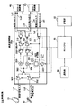
- FIG. 4 illustrates a configuration example of the reception device 1 according to the first embodiment of the present disclosure.
- the receiving device 1 includes a parabolic antenna 10 for receiving satellite broadcasts, a UHF antenna 20 for receiving terrestrial digital broadcasts and cable television broadcasts, a high-frequency processing unit 30, and a demodulator 40.
- the high-frequency processing unit 30 includes an AGC amplifier 301 and an AGC amplifier 302, a switch 303 that selectively switches the outputs of the AGC amplifier 301 and the AGC amplifier 302, an I / Q mixer 304 as a first mixer, and a second mixer As an I / Q mixer 305. Also, a PLL unit 320 as a local oscillator, a phase shifter 306, a variable LPF 307 as a first filter, a variable LPF 308 as a second filter, a baseband amplifier 309 and a baseband amplifier 310 are provided.
- the satellite IF signal received by the parabolic antenna 10 is input to the AGC amplifier 301 in the high-frequency processing unit 30 via the signal line Li1.
- the AGC amplifier 301 amplifies and outputs the satellite IF signal input from the signal line Li1 based on the AGC control signal input from the demodulator 40 via the signal line La.
- the terrestrial RF signal or the cable television broadcast RF signal (hereinafter also simply referred to as “RF signal”) received by the UHF antenna 20 is input to the AGC amplifier 302 in the high-frequency processing unit 30 via the signal line Li2. .
- the AGC amplifier 302 amplifies and outputs the RF signal input from the signal line Li2 based on the AGC control signal input from the demodulator 40.
- the difference in level between both signals input to the high-frequency processing unit 30 is covered. can do.
- the AGC amplifier 301 and the AGC amplifier 302 may be configured by one amplifier by using an AGC amplifier having a wide gain variable range.
- the satellite IF signal amplified by the AGC amplifier 301 and the terrestrial digital broadcast or cable television broadcast RF signal amplified by the AGC amplifier 302 are connected to a terminal of the switch 303. Then, by selectively switching the connection destination of the switch 303, either the satellite IF signal or the RF signal of the terrestrial digital broadcast or the cable television broadcast is input to the I / Q mixer 304 and the I / Q mixer 305.
- the I / Q mixer 304 mixes either the satellite IF signal or the RF signal selected by the switch 303 and the oscillation signal (local signal) output from the PLL unit 320 to obtain an I-phase baseband. retrieve the signal.
- the I / Q mixer 305 outputs one of the satellite IF signal and the RF signal selected by the switch 303, the oscillation signal output from the PLL unit 320 and shifted in phase by 90 ° by the phase shifter 306. To extract a Q-phase baseband signal.
- the PLL unit 320 generates a local signal having the same frequency as the reception frequency desired to be received by the parabolic antenna 10 or the UHF antenna 20 as a local oscillator, and supplies the generated local signal to the I / Q mixer 304 and the phase shifter 306. To do.
- the phase shifter 306 shifts the phase of the oscillation signal input from the PLL unit 320 by 90 ° and inputs it to the I / Q mixer 305.
- a fractional N type PLL circuit capable of fractional frequency division is used as the PLL unit 320.
- FIG. 5 shows a configuration example of the PLL unit 320 configured by a fractional N type PLL circuit.
- the fractional frequency division means frequency division including a decimal point in the frequency divided as described later.
- the PLL unit 320 includes a crystal oscillator 321 that oscillates a reference signal, a frequency divider 322, a phase comparator 323, a loop filter 324, and a VCO 325.
- Frequency divider 322 includes an R counter 322r and an N counter 322n.
- the reference signal oscillated by the crystal oscillator 321 is input to the R counter 322r and is divided by R, that is, 1 / R times by the R counter 322r.
- the frequency divided by R by the R counter 322r is input to the phase comparator 323 as a comparison frequency.
- the phase comparator 323 compares the phase of the comparison frequency input from the R counter 322r with the phase of the oscillation signal oscillated by the VCO 325 and divided by the N counter 322n, and a signal (error signal) corresponding to the phase difference. ) Is input to the loop filter 324.
- the loop filter 324 converts the error signal input from the phase comparator 323 into a DC voltage and applies the VCO 325.
- the VCO 325 changes the frequency of the oscillation signal to be oscillated according to the magnitude of the DC voltage applied from the loop filter 324, and supplies the oscillated oscillation signal to the N counter 322n.
- the oscillation frequency of the VCO is set to be twice or more the reception frequency because a 90 ° phase difference signal can be easily obtained.
- the receiving apparatus 1 it is necessary to receive a satellite broadcast wave transmitted using a high frequency band (950 MHz to 2150 MHz), so that the output frequency range of the VCO 325 is 2200 MHz to 4400 MHz. Yes.
- the LC resonance circuit used in the tuning unit of the VCO 325 is provided with a coil (tuning inductance) inside an IC (Integrated Circuit).
- a coil tuning inductance
- IC Integrated Circuit
- a coil is mounted in a bare chip state on a substrate made of LTCC (Low Temperature Co-fired Ceramic) or the like and covered with a resin mold without wire bonding.
- LTCC Low Temperature Co-fired Ceramic
- a resin mold without wire bonding By configuring in this way, an oscillator can be configured without using bonding wires, so that the value of the parasitic inductance can be kept small compared to the case where the LC resonance circuit is configured with, for example, a BGA (Ball Grid Array). It becomes possible.
- the oscillation frequency of the VCO 325 is very high as described above.
- the value of the tuning inductance L is required to be small.
- the value of the tuning inductance L is preferably a small value of about 10 nH, for example.
- the influence of parasitic inductance on the resonance frequency is increased. That is, the greater the parasitic inductance, the higher the possibility of resonance frequency shift and parasitic oscillation.
- the LC resonance circuit portion of the VCO 325 is configured by incorporating a coil in the IC, so that the parasitic inductance can be suppressed to a level where the influence can be ignored. As a result, resonance frequency shift and parasitic oscillation are less likely to occur, so that the oscillation operation of the VCO 325 is stabilized. Furthermore, the number of circuit components can be reduced by forming a coil in the IC. Further, as a configuration in which the coil is built in the IC, a spiral coil may be configured by drawing a pattern of a conductive portion on the silicon chip. With this configuration, the parasitic inductance can be suppressed to a lower value.
- the Q value becomes lower than that in the case of using an air-core coil as the tuning inductance L of the resonance circuit, for example.
- the comparison frequency by increasing the comparison frequency, the phase noise in the loop band can be reduced.
- the PLL unit 320 is configured by a fractional N type PLL circuit, it is possible to increase the comparison frequency while keeping the minimum step frequency small. That is, not only the required characteristics of the tuner required at the time of receiving the satellite broadcast, but also the required characteristics required at the time of receiving the terrestrial digital broadcast or cable television broadcast can be satisfied.
- the N counter 322n includes a variable frequency divider and an accumulator (not shown).
- the variable frequency divider includes an N frequency divider that divides the frequency of the oscillation signal input from the VCO 325 by N, and an N + 1 frequency divider that divides the frequency by N + 1.
- the accumulator selects the N + 1 divider for K times out of the F pulses (count value) output from the variable frequency divider, and selects the N divider for FK times. With this configuration, (N + K / F) is equivalently obtained as the average frequency dividing number.
- N 900 MHz
- F 5
- K 1
- the output frequency from the N counter 322n 900 MHz.
- the values set for N, F, and K are examples, and are not limited to these examples.
- the frequency division ratio of the frequency divider 322 including the R counter 322r and the N counter 322n can be switched between 2 and 64.
- the frequency range that can be oscillated by the PLL unit 320 can be a wide range from 34.375 MHz (2200 MHz / 64 division) to 2200 MHz (4400 MHz / 2 division).
- the frequency band of the satellite IF signal but also the VHF band and the UHF band, which are frequency bands of terrestrial digital broadcasting or cable television broadcasting, can be generated from the PLL unit 320.
- the oscillation signal (local signal) output from the PLL unit 320 is mixed with the satellite IF signal or the RF signal by the I / Q mixer 304 and the I / Q mixer 305 to obtain the I phase. And converted to a Q-phase baseband signal.
- the baseband signals of the I phase and the Q phase are input to the variable LPF 307 and the variable LPF 308, respectively.
- the variable LPF 307 limits the frequency of the I-phase baseband signal to a predetermined band and outputs it to the baseband amplifier 309. Further, the variable LPF 308 limits the frequency of the Q-phase baseband signal to a predetermined band and outputs it to the baseband amplifier 310.
- variable LPF 307 and the variable LPF 308 are configured as programmable variable LPFs. That is, the cutoff frequency is set as a set value in a register (not shown). In the present embodiment, the setting range is 3 MHz to 20 MHz. By setting in this way, both the terrestrial digital broadcast or cable television broadcast wave with an occupied bandwidth of 6 MHz to 8 MHz and the broadcast wave of a satellite broadcast with an occupied bandwidth of 20 MHz to 40 MHz are both variable LPF 307 and variable LPF 308. It will be obtained by passing.
- the gain of the I-phase baseband signal that has passed through the variable LPF 307 is adjusted by the baseband amplifier 309 and then input to the demodulator 40 through the signal line Lo2.
- the Q-phase baseband signal that has passed through the variable LPF 308 is input to the demodulator 40 through the signal line Lo ⁇ b> 1 after its gain is adjusted by the baseband amplifier 310.
- the gains of the baseband amplifier 309 and the baseband amplifier 310 are adjusted based on the AGC control signal input from the demodulator 40 through the signal line La.
- FIG. 6 is a diagram showing an image of baseband signal extraction (baseband conversion) by the I / Q mixers 304 and 305 and band limitation by the variable LPF 307 and the variable LPF 308.
- the horizontal axis in FIG. 6 indicates the frequency (MHz), and the vertical axis indicates the signal level.
- FIG. 6 shows an example of detecting a 557 MHz signal set as a reception frequency among the RF signals received by the UHF antenna 20.
- the PLL unit 320 (see FIG. 1) generates a local signal having the same frequency as the reception frequency, that is, 557 MHz.
- the local signal is multiplied by the RF signal amplified by the AGC amplifier 302 (see FIG. 1) by the I / Q mixer 304 and the I / Q mixer 305.
- a signal having a center frequency fc of 557 MHz which is the same as the frequency of the local signal (local frequency) and a bandwidth Bw1 of 6 MHz is extracted and subjected to baseband conversion. That is, the RF signal received by the UHF antenna 20 and amplified by the AGC amplifier 302 is converted into a baseband signal having a center frequency fc of 0 MHz. Further, the baseband signal thus extracted passes through the variable LPF 307 and the variable LPF 308, so that the bandwidth Bw2 is band-limited to 1 ⁇ 2. That is, the receiving apparatus 1 according to the present embodiment performs detection by the direct conversion method.
- the demodulator 40 demodulates each input I-phase / Q-phase baseband signal by a predetermined demodulation method, and outputs it as a TS (Transport Stream) signal.
- the demodulator 40 is configured so as to be able to demodulate by a demodulation method corresponding to each broadcasting standard of terrestrial digital broadcasting, cable television broadcasting, and satellite broadcasting.
- the modulation method used in ISDB-T which is a broadcasting format for digital terrestrial broadcasting
- the modulation method used in cable television broadcasting and the modulation method used in ISDB-S, which is a broadcasting format for satellite broadcasting.
- the signal is demodulated by a demodulation method corresponding to the method.
- the TS signal demodulated by the demodulator 40 is decoded by an MPEG (Moving / Picture / Experts / Group) decoder (not shown) to extract a video signal and an audio signal.
- MPEG Motion Picture / Experts / Group
- the receiving device 1 includes a channel selection unit 50, a storage unit 60, and a host CPU 70 as a control unit.
- the channel selection unit 50 is configured by a remote controller or the like, and transmits information on a channel selected by the user to a host CPU (Central / Processing / Unit) 70 as channel selection data.
- the storage unit 60 includes a non-volatile memory or the like, and stores channel selection data and setting data corresponding thereto. Note that the channel selection data is not generated only when a channel is selected via the channel selection unit 50 configured as a remote controller. For example, it is assumed that channel selection data is also generated when a specific program is selected via an electronic program guide (EPG) or when a specific program is selected as a recording reservation.
- EPG electronic program guide
- the host CPU 70 controls each part of the receiving device 1.
- the host CPU 70 reads setting data necessary for receiving the broadcast of the selected channel from the storage unit 60 based on the channel selection data, and reads the setting.
- Each unit of the receiving device 1 is set based on the data.
- FIG. 7 is a flowchart showing an example of control by the host CPU 70.
- the host CPU 70 reads channel selection data transmitted from the channel selection unit 50 or channel selection data generated based on channel selection performed through EPG or recording reservation (step S1). Then, it is determined whether the selected channel is a terrestrial digital broadcast channel (step S2). If the channel is a terrestrial digital broadcast channel, settings for receiving the terrestrial digital broadcast are made for each part of the receiving apparatus 1 (step S3), and the process returns to step S1. If it is determined in step S2 that the selected channel is not a terrestrial digital broadcast channel, it is next determined whether or not the selected channel is a cable television broadcast channel (step S4). ). If it is determined that the channel is a cable television broadcast channel, the cable television broadcast reception setting is performed for each part of the receiving device 1 (step S5), and the process returns to step S1.
- step S4 If it is determined in step S4 that the selected channel is not a cable television broadcast channel, it is next determined whether or not the selected channel is a satellite broadcast channel (step S6). If it is determined that the channel is a satellite broadcast channel, settings for receiving the satellite broadcast are made for each part of the receiving device 1 (step S7), and the process returns to step S1. Also, if the selected channel does not correspond to any of the above-mentioned broadcasts, the process returns to step S1.
- FIG. 8 shows an example of settings performed by the host CPU 70.
- Setting items include "switch connection destination”, “VCO output frequency”, “frequency divider ratio”, “variable LPF cutoff frequency”, and “demodulator broadcast standard (demodulation method)”. .
- the setting performed by the host CPU 70 when a digital terrestrial broadcast channel is selected will be described.
- the connection destination of the switch 303 (see FIG. 4) is switched to the AGC amplifier 302 side.
- the RF signal received by the UHF antenna 20 and amplified by the AGC amplifier 302 is input to the I / Q mixer 304 and the I / Q mixer 305 via the switch 303.
- the output frequency of the VCO 325 of the PLL unit 320 is set to an appropriate frequency within the range of 2200 MHz to 4400 MHz. That is, a frequency corresponding to the reception frequency determined by the selected channel is oscillated as an output frequency from the range of 2200 MHz to 4400 MHz.
- the frequency division ratio of the frequency divider 322 is set to an appropriate value between 4 and 64.
- variable LPF 307 and the variable LPF 308 are set to appropriate values between 3 MHz and 4 MHz. Thus, only the frequency of 6 MHz to 8 MHz, which is the bandwidth for one channel of terrestrial digital broadcasting, is passed by the variable LPF 307 and the variable LPF 308.
- the broadcast system supported by the demodulator is switched to the ISDB-T system, and the OFDM system and the 8VSB system are set as the demodulation system.
- a demodulation method corresponding to a modulation method for cable television broadcast transmission that is, a demodulation method such as 64QAM, 128QAM, or 256QAM is selected.
- the connection destination of the switch 303 (see FIG. 4) is switched to the AGC amplifier 301 side by the host CPU 70.
- the satellite IF signal received by the parabolic antenna 10 and amplified by the AGC amplifier 301 is input to the I / Q mixer 304 and the I / Q mixer 305 via the switch 303.
- the output frequency of the VCO 325 of the PLL unit 320 is set to an appropriate frequency within the range of 2200 MHz to 4400 MHz. That is, a frequency corresponding to the reception frequency determined by the selected channel is oscillated as an output frequency from the range of 2200 MHz to 4400 MHz.
- the frequency division ratio of the frequency divider 322 is set to an appropriate value between 2 and 4.
- variable LPF 307 and the variable LPF 308 are set to appropriate values between 10 MHz and 20 MHz.
- the variable LPF 307 and the variable LPF 308 pass only the frequency of 20 MHz to 40 MHz, which is the bandwidth for one channel of satellite broadcasting.
- the broadcast system supported by the demodulator is switched to the ISDB-S system, and the QPSK system or the 8PSK system is set as the demodulation system.
- the setting of each unit constituting the high frequency processing unit 30 (see FIG. 4) and the setting of the demodulator 40 are converted into channel selection data under the control of the host CPU 70. You can switch to the one that matches.
- a single high frequency processing unit 30 and demodulator 40 can receive a plurality of broadcast waves having different broadcasting methods, such as terrestrial digital broadcasting and satellite broadcasting. Therefore, the scale of the circuits constituting the high-frequency processing unit 30 and the demodulator 40 is greatly reduced, and the circuit mounting area is also reduced. Therefore, it is possible to reduce the size of the receiving device 1 and reduce the manufacturing cost.
- the terrestrial digital broadcast wave and the cable television broadcast wave are also demodulated by the direct conversion method. That is, since it is not necessary to convert the received signal into an IF signal as in the case of detection by the superheterodyne method, the circuit configuration can be simplified and the circuit can be reduced in size.
- the PLL unit 320 is configured by a fractional N-type PLL circuit. Thereby, the minimum step frequency of the PLL unit 320 (frequency divider 322) can be reduced. In other words, since the frequency of the local signal can be switched with a fine step width, it is possible to set a fine minimum step frequency of 125 kHz to 166.7 kHz required when receiving digital terrestrial broadcasting or cable television broadcasting. .
- the loop gain near the center frequency of the VCO 325, for example, at a 1 kHz offset point is increased. Thereby, the phase noise in the loop band can be reduced. Accordingly, it is possible to satisfy the phase noise performance of 1 kHz or less required for a receiving apparatus for digital terrestrial broadcasting or cable television broadcasting.
- the LPF that limits the band of the I-phase or Q-phase baseband signal generated by the I / Q mixers 304 and 305 is configured as a variable LPF.
- the high-frequency processing units that handle different broadcast waves have the same circuit configuration, and the arrangement of each high-frequency processing unit is determined by the satellite IF signal or RF obtained by the antenna. It is effective to use a point where a signal is input as a midpoint and make it symmetric. According to the receiving apparatus 1 of the present embodiment, since the number of high-frequency processing units can be reduced, such a circuit configuration can be realized relatively easily. Therefore, it is easy to cope with an increase in the TS signal processing system in the decoder.
- FIG. 9 shows an ISDB-S demodulator 40s (first demodulator) that demodulates a broadcast wave of satellite broadcasting, an ISDB-T demodulator 40t (second demodulator) that demodulates a broadcast wave of digital terrestrial broadcasting, and Shows an example of the configuration of the receiving device 1 ⁇ in the case where each is provided individually. 9, parts corresponding to those in FIG. 4 are given the same reference numerals, and detailed description thereof is omitted.
- each of the ISDB-S demodulator 40s and the ISDB-T demodulator 40t has two input terminals.
- a switch 311 and a switch 312 for switching the output destinations of the baseband amplifier 309 and the baseband amplifier 310 are provided.
- a switch 313 for switching the output destination of the AGC control signal is also provided.
- the control by the host CPU 70 is the same as that shown in FIG.
- the connection destination of the switch 311 and the switch 312 is switched to the ISDB-S demodulator 40 s side based on the control of the host CPU 70. That is, the signal line Lo1 and the signal line Lo2 connected to the ISDB-S demodulator 40s are connected. As a result, the I-phase and Q-phase baseband signals extracted from the satellite IF signal are input to the ISDB-S demodulator 40s and demodulated. Also, the connection destination of the switch 313 is switched to the ISDB-S demodulator 40s side. That is, it is connected to the control line La1 connected to the ISDB-S demodulator 40s.
- the AGC control signal for satellite broadcast reception generated by the ISDB-S demodulator 40s is input to the AGC amplifier 301 and the AGC amplifier 302, the baseband amplifier 309, and the baseband amplifier 310 via the control line La1. Is done.
- the connection destination of the switch 311 and the switch 312 is switched to the ISDB-T demodulator 40t side under the control of the host CPU. That is, the signal line Lo3 and the signal line Lo4 connected to the ISDB-T demodulator 40t are connected. As a result, the I-phase and Q-phase baseband signals extracted from the RF signal are input to the ISDB-T demodulator 40t and demodulated. Also, the connection destination of the switch 313 is switched to the ISDB-T demodulator 40t side. That is, it is connected to the control line La2 connected to the ISDB-T demodulator 40t.
- the AGC control signal for terrestrial digital broadcast reception generated by the ISDB-T demodulator 40t is transmitted to the AGC amplifier 301 and the AGC amplifier 302, the baseband amplifier 309 and the baseband amplifier 310 via the control line La2. Entered.
- broadcast waves can be received in various combinations such as satellite broadcast and cable television broadcast, satellite & satellite, ground wave & ground wave, and the like.
- a part of the high-frequency processing unit can be energized and activated at any time even when the broadcast is not actually received. So that it is done.
- a high frequency processing unit is provided in proportion to the type of broadcast wave to be received or the type of combination, standby power consumption consumed in such a state also increases.
- a single high-frequency processing unit 30 ⁇ can receive a plurality of types of broadcast waves in various combinations. That is, standby power consumption can be greatly reduced.
- the receiving apparatus 1 ⁇ includes a high-frequency processing unit 30s that detects a satellite IF signal by a direct conversion method and a high-frequency processing unit 30t that detects a terrestrial RF signal by a superheterodyne method. At the time of broadcast reception, any one of them is alternatively selected by the switching unit 200 as the first switching unit.
- the switching unit 200 includes a switch 201 and a switch 202.
- the switch 201 turns on or off the connection between the AGC amplifier 301 of the high-frequency processing unit 30 s on the satellite broadcast reception side and the first mixer 304 and the second mixer 305 in the subsequent stage.
- the switch 202 turns on or off the connection between the AGC amplifier 601 of the high frequency processing unit 30t on the terrestrial digital broadcast receiving side and the subsequent mixer 602.
- the switching operation of the switches 201 and 202 by the switching unit 200 is controlled by the host CPU 70 (see FIGS. 4 and 9) as a control unit.
- the host CPU 70 instructs the switching unit 200 to perform a switching operation at a timing when new channel selection data is supplied from the channel selection unit 50.
- the host CPU 70 also controls the high-frequency processing unit 30 on the side where no broadcast wave is received to enter the power-off mode.
- the power-off mode is a block (output amplifier) that outputs a signal to an A / D (Analog / Digital) converter (not shown) connected in a subsequent stage among the blocks that constitute the high-frequency processing unit 30.
- a / D Analog / Digital
- FIG. 10 illustrates baseband amplifiers 309 and 310 in the high-frequency processing unit 30s and an IF amplifier 605 in the high-frequency processing unit 30t.
- a predetermined bias voltage is always applied to the baseband amplifiers 309 and 310 of the high frequency processing unit 30s and the IF amplifier 605 of the high frequency processing unit 30t so that the bias voltage is output as a DC voltage when the power supply off mode is set. Keep it.
- the bias voltage By setting the bias voltage to such a value that the output voltage of these output amplifiers becomes the midpoint potential, even in a connection state in which the A / D converter is directly connected to the subsequent stage, It is possible to prevent the input terminal of the A / D converter from entering an indefinite state.
- the PLL unit 320 as a local oscillator is shared by the high frequency processing unit 30s and the high frequency processing unit 30t.
- the PLL unit 320 is configured as a fractional N-type PLL circuit, similar to the one shown in the first embodiment.
- output buffer amplifiers that buffer local oscillation signals output from the frequency divider 322 of the PLL unit 320 are provided corresponding to the number of output destinations.
- an output buffer amplifier 701 that buffers local oscillation signals input to the mixers 304 and 305 of the high frequency processing unit 30s and an output buffer amplifier 702 that buffers signals input to the mixer 602 of the high frequency processing unit 30t are provided. It is configured. Further, a switch 801 for turning on / off the connection between the frequency divider 322 and the mixers 304 and 305 and a switch 802 for turning on / off the connection between the frequency divider 322 and the mixer 602 are also provided.
- the connection destination of the switching unit (second switching unit) 800 composed of the switches 801 and 802 is alternatively selected by the host CPU 70 (see FIG. 4 and the like).
- the host CPU 70 turns on the switch connected to the mixer of the high-frequency processing unit 30 on the side where the power-off mode is not set, that is, the side receiving the broadcast signal, and the high-frequency processing unit 30 on the side where the power-off mode is set
- the switch connected to the mixer is turned off. For example, when receiving a satellite broadcast, the switch 801 connected to the mixers 304 and 405 of the high-frequency processing unit 30s is turned on, and the switch 802 connected to the mixer 602 of the high-frequency processing unit 30t is turned off.
- the host CPU 70 applies a predetermined voltage such as 1.5 V to the output buffer amplifier on the side connected to the mixer after the switch is turned on. Control to set the impedance to a predetermined high value is also performed. By performing such control, the total load when the buffer side is viewed from the frequency divider 322 is always 1.5V. Therefore, even when one of the high frequency processing units 30 is turned off and the mixer to which the local oscillation signal is output is turned off, the impedance mismatch between the frequency divider 322 and the mixer is caused. Will no longer occur.
- a predetermined voltage such as 1.5 V
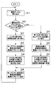
- the host CPU 70 reads channel selection data (step S11), and determines whether the selected channel is a terrestrial digital broadcast channel (step S12). If the channel is a terrestrial digital broadcast channel, the connection destination of the switching unit 200 as the first input switching unit is switched to the high-frequency processing unit 30t on the terrestrial digital broadcast reception side (step S13). Then, the high-frequency processing unit 30s on the satellite broadcast receiving side is set to the power-off mode (step S14), and the above-described processing is performed.
- step S15 the VCO output frequency of the PLL unit 320 and the frequency dividing ratio of the frequency divider 322 are set to values suitable for receiving terrestrial digital broadcasting (step S15), and the broadcast signal, here, the terrestrial RF signal is detected. Processing is performed (step S16).
- step S12 If it is determined in step S12 that the selected channel is a satellite broadcast channel, the host CPU 70 switches the connection destination of the switching unit 200 to the high frequency processing unit 30s on the satellite broadcast reception side (Ste S17). Then, control is performed to set the high-frequency processing unit 30t on the digital terrestrial broadcasting reception side to the power-off mode (step S18). Subsequently, the VCO output frequency of the PLL unit 320 and the frequency division ratio of the frequency divider 322 are set to values suitable for satellite broadcast reception (step S19), and a process of detecting a broadcast signal, here a satellite IF signal, is performed. This is performed (step S16). After the process so far is performed, the process returns to step S11 and the process is continued.
- the high-frequency processing unit 30 on the side that does not receive the broadcast signal is in the power-off mode and power supply is stopped, so that power consumption can be suppressed.
- current is supplied to the baseband amplifiers 309 and 310 as output amplifiers and the IF amplifier 605, and the output voltage is controlled to be a predetermined DC voltage (midpoint potential).
- the input terminal of the A / D converter is not in an indefinite state.
- the output of the frequency divider 322 is distributed corresponding to the output destination, and the connection destination receives the broadcast signal by the switching unit 800 as the second switching unit.
- the high frequency processing unit 30 on the side is switched.
- a predetermined voltage is applied to the output buffer amplifier on the side where the switch is connected, and the output buffer amplifier on the side where the switch is turned off is controlled to have a high impedance.
- the circuit scale can be reduced.
- the broadcast signal is detected by switching between the high-frequency processing unit 30t for receiving terrestrial digital broadcasts and the high-frequency processing unit 30s for receiving satellite broadcasts.
- the configuration can be utilized as it is. That is, it is possible to relatively easily perform processing such as adding a high-frequency processing unit 30s that performs detection by the direct conversion method for satellite broadcast reception to the existing configuration.
- a plurality of local oscillators may be provided corresponding to each high-frequency processing unit 30. In this case, power is not supplied except for the local oscillator that supplies the local oscillation signal to the high-frequency processing unit that is receiving the broadcast signal. By doing so, the power consumption in the receiving apparatus 1 can be kept low.
- the present invention is not limited to this.
- the present invention may be applied to a configuration in which a plurality of local oscillators are provided corresponding to the respective bands constituting the reception frequency band.
- this indication can also take the following structures.
- a first high-frequency processing unit that detects a first broadcast wave transmitted using the first frequency band and extracts a first high-frequency signal
- a second high-frequency processing unit that detects a second broadcast wave transmitted using a second frequency band different from the first frequency band and extracts a second high-frequency signal
- a receiving apparatus comprising: the first high-frequency processing unit; and at least one local oscillator that generates a local oscillation signal used in the second high-frequency processing unit.
- the at least one local oscillator includes a fractional N-type PLL circuit.
- a first switching unit that switches between the first high-frequency processing unit and the second high-frequency processing unit;
- a control unit that switches a connection destination of the first switching unit to a high-frequency processing unit on a broadcast wave receiving side;
- the at least one local oscillator supplies the local oscillation signal to a high-frequency processing unit selected by the first switching unit among the first high-frequency processing unit and the second high-frequency processing unit.
- the receiving device according to (1) or (2).
- a first output amplifier that amplifies the local oscillation signal generated by the local oscillator and outputs the amplified signal to the first high-frequency processing unit, and amplifies the local oscillation signal to generate the second high-frequency processing unit.
- a second output amplifier that outputs to The control unit, when setting the power-off mode, of the first high-frequency processing unit and the second high-frequency processing unit, among the processing units in the high-frequency processing unit set to the power-off mode, The receiving device according to (4), wherein control is performed to stop supply of current to processing units other than the first output amplifier or the second output amplifier.
- the control unit applies a predetermined bias voltage to the first output amplifier and the second output amplifier, and when the power-off mode is set, the first output amplifier and the second output amplifier are set.
- the receiving device according to (4) or (5), wherein a bias voltage to the output amplifier is output as an output voltage from the output amplifier set to the power-off mode among the output amplifiers.
- a first output buffer amplifier that amplifies the local oscillation signal output from the frequency divider and outputs the amplified signal to the first high frequency processing unit; and the local oscillation signal output from the frequency divider.
- a second output buffer amplifier that amplifies and outputs to the second high-frequency processing unit, and the first output buffer amplifier and the second output buffer amplifier are alternatively selected and connected to a subsequent circuit.
- a second switching unit that When the power-off mode is set, the control unit switches the connection destination of the second switching unit to the output buffer amplifier connected to the high-frequency processing unit on the broadcast wave reception side, and enters the power-off mode.
- the receiving apparatus according to any one of (4) to (6), wherein control is performed so that the impedance of the output buffer amplifier connected to the set high-frequency processing unit is a predetermined high value.
- the receiving device according to (1) or (2), wherein at least one of the first frequency band and the second frequency band is a frequency band for satellite broadcasting.
- At least one of the first high frequency processing unit and the second high frequency processing unit performs detection by a direct conversion method
- the high-frequency processing unit that performs detection by the direct conversion method amplifies one of the first high-frequency signal and the second high-frequency signal, and the first high-frequency signal and the second high-frequency signal.
- Each low noise amplifier corresponding to the signal;
- a first mixer that extracts the I-phase baseband signal by mixing the first high-frequency signal or the second high-frequency signal amplified by the low-noise amplifier and the local signal; and the low-noise amplifier.
- a second mixer for extracting a Q-phase baseband signal by mixing the first high-frequency signal or the second high-frequency signal amplified in step S and the signal obtained by shifting the phase of the local signal by 90 °;
- a first filter that limits a frequency of the I-phase baseband signal to a predetermined band;
- a second filter that limits the frequency of the Q-phase baseband signal to a predetermined band;
- a demodulator Based on tuning information set by the user, the oscillation frequency of the local oscillator, the frequency division ratio of the frequency divider in the local oscillator, the cutoff frequency of the first filter and the second filter,
- the receiving device according to (1) or (2), further comprising a control unit configured to set a demodulation method of the demodulator.
- the first filter and the second filter are configured as variable low-pass filters capable of setting an arbitrary cutoff frequency, and the lower limit value of the cutoff frequency is the first broadcast wave and the second filter Of the broadcast wave having the lower frequency band is determined according to the occupied bandwidth of the carrier wave of the lower broadcast band, and the upper limit value of the cut-off frequency is the first broadcast wave and the second broadcast wave.
- the local oscillator includes a crystal oscillator, the frequency divider, a phase comparator, a loop filter, and a voltage-controlled oscillator, and the setting lower limit value of the frequency division ratio of the frequency divider is the first
- the receiving device according to any one of (9) and (10), which is determined according to a value of an upper limit frequency of the higher frequency band of the broadcast wave of the second broadcast wave and the second broadcast wave .
- the voltage control oscillator of the local oscillator includes an LC resonance circuit, and a coil used in the LC resonance circuit is built in an integrated circuit.
- the demodulator performs a first demodulator that performs demodulation according to the modulation scheme used in the first broadcast, and a first demodulator that performs demodulation according to the modulation scheme used in the second broadcast.
- 2 demodulator A first switch that switches an output destination of the I-phase baseband signal between the first demodulator side and the second demodulator side; an output destination of the Q-phase baseband signal; A second switch for switching between the demodulator side and the second demodulator side;
- the receiving device according to any one of (9) to (11), wherein the control unit switches a connection destination of the first switch and the second switch based on channel selection information set by the user.
- the first high-frequency processing unit detects the first broadcast wave transmitted using the first frequency band and extracts the first high-frequency signal;
- a second high-frequency processing unit detects a second broadcast wave transmitted using a second frequency band different from the first frequency band, and extracts a second high-frequency signal;
- a reception method comprising: at least one local oscillator generating a local oscillation signal used in the first high-frequency processing unit and the second high-frequency processing unit.
- switch 604 ... BPF, 605 ... IF amplifier, 610 ... local oscillator 611 to 613, VCO, 620, ISDB-T demodulator, 701, 702, output buffer amplifier, 800, second switching unit, 801, 802, switch, 901 to 906, distributor, 3201, 3202, 3203,.
- PLL section B1 to B3 ... detection block, Bw1, Bw2 ... bandwidth, La1, La10, La2, La20 Control line, Li1, Li10, Li2, Li20, Lo1, Lo2 ... signal line
Abstract
Description
1.第1の実施の形態例(放送方式の異なる複数の放送波を単一の検波方式で受信する構成の例)
1-1.前提となる技術の説明
1-2.第1の実施の形態による構成例(復調器を1台で構成した例)
1-3.各種変形例
2.第2の実施の形態例(放送方式の異なる複数の放送波を扱う複数の高周波処理部で、一つの局部発振器を共用する構成の例) First, a technology that is a premise of the present disclosure will be described with reference to FIGS. 1 to 3, and then a configuration example of a receiving device according to an embodiment of the present disclosure will be described in the following order. However, the present disclosure is not limited to the following example.
1. First embodiment (example of a configuration for receiving a plurality of broadcast waves having different broadcast systems by a single detection system)
1-1. Explanation of prerequisite technology 1-2. Configuration example according to the first embodiment (example in which one demodulator is configured)
1-3.
<1-1.本実施の形態の前提となる技術>
現在、衛星放送の放送波の検波(復調)は、「ダイレクトコンバージョン方式」と称される方式で行われている。ダイレクトコンバージョン方式では、受信した放送波から直接ベースバンド信号が取り出される。地上デジタル放送やケーブルテレビ放送の検波は、「スーパーヘテロダイン方式」と称される方式で行われている。「スーパーヘテロダイン方式」では、受信電波の周波数が特定の中間周波数(IF)に変換されてから検波される。 [1. First Embodiment]
<1-1. Technology Premised on this Embodiment>
Currently, detection (demodulation) of broadcast waves of satellite broadcasting is performed by a method called “direct conversion method”. In the direct conversion method, a baseband signal is directly extracted from a received broadcast wave. Detection of terrestrial digital broadcasting and cable television broadcasting is performed by a method called “superheterodyne method”. In the “superheterodyne method”, the frequency of a received radio wave is detected after being converted to a specific intermediate frequency (IF).
shift keying)等の方式がある。また、ISDB-S復調器520はAGC制御信号を生成し、生成したAGC制御信号を、制御ラインLa10を介して、AGCアンプ501とベースバンドアンプ507およびベースバンドアンプ508に供給する。 The ISDB-
shift keying). Further, the ISDB-
modulation)、64QAM等の方式がある。また、ISDB-T復調器620は、AGC制御信号を生成し、生成したAGC制御信号を、信号線La20を介してAGCアンプ601とIFアンプ605に供給する。 The ISDB-
modulation) and 64QAM. Further, the ISDB-
次に、本開示の第1の実施の形態例に係る受信装置について、図4~図7を参照して説明する。図4は、本開示の第1の実施の形態例に係る受信装置1の構成例を示したものである。受信装置1は、衛星放送受信用のパラボラアンテナ10と、地上波デジタル放送とケーブルテレビ放送受信用のUHFアンテナ20と、高周波処理部30と、復調器40とを備える。 <1-2. Configuration example of receiving apparatus according to first embodiment>
Next, the receiving device according to the first embodiment of the present disclosure will be described with reference to FIGS. FIG. 4 illustrates a configuration example of the
なお、上述した実施の形態では、1台の復調器40が、ISDB-TやISDB-S等の異なる放送規格における各種復調方式に応じた復調を行う例をあげたが、これに限定されるものではない。受信する放送波の種類に応じて、復調器を複数台設けるようにしてもよい。図9は、衛星放送の放送波を復調するISDB-S復調器40s(第1の復調器)と、地上デジタル放送の放送波を復調するISDB-T復調器40t(第2の復調器)とを個別に設けた場合の、受信装置1αの構成例を示したものである。図9において、図4に対応する箇所には同一の符合を付してあり、詳細な説明は省略する。 <1-3. Various modifications>
In the above-described embodiment, an example in which one
<2-1.受信装置の構成例>
次に、本開示の第2の実施の形態による受信装置1βの構成例について、図10のブロック図を参照して説明する。図10において、図1,図2,図4,図9と対応する箇所には同一の符号を付してあり、重複する説明は省略する。 [2. Second embodiment]
<2-1. Configuration example of receiving device>
Next, a configuration example of the reception device 1β according to the second embodiment of the present disclosure will be described with reference to the block diagram of FIG. 10, portions corresponding to those in FIGS. 1, 2, 4, and 9 are denoted by the same reference numerals, and redundant description is omitted.
次に、図11のフローチャートを参照して、本実施の形態による受信装置1βの受信処理の例について説明する。まず、ホストCPU70が選局データを読込み(ステップS11)、選局されたチャンネルが、地上デジタル放送のチャンネルであるか否かを判断する(ステップS12)。地上デジタル放送のチャンネルであった場合には、第1の入力切り替え部としての切り替え部200の接続先を、地上波デジタル放送受信側の高周波処理部30tに切り替える(ステップS13)。そして、衛星放送受信側の高周波処理部30sを電源オフモードの設定とし(ステップS14)、上述したような処理を行う。続いて、PLL部320のVCO出力周波数と分周器322の分周比を、地上デジタル放送受信用に適した値に設定し(ステップS15)、放送信号、ここでは地上波RF信号を検波する処理を行う(ステップS16)。 <2-2. Example of reception processing of reception device>
Next, an example of reception processing of the reception device 1β according to the present embodiment will be described with reference to the flowchart of FIG. First, the
源オフモードとなって電力の供給が停止されるため、消費電力が抑えられるようになる。このとき、出力アンプとしてのベースバンドアンプ309および310と、IFアンプ605に対しては電流が供給され、出力電圧が所定のDC電圧(中点電位)となるような制御がされるため、後段のA/Dコンバータの入力端子が不定状態となってしまうことがなくなる。 Further, according to the above-described embodiment, the high-
(1)第1の周波数帯域を用いて伝送される第1の放送波を検波して第1の高周波信号を取り出す第1の高周波処理部と、
前記第1の周波数帯域とは異なる第2の周波数帯域を用いて伝送される第2の放送波を検波して第2の高周波信号を取り出す第2の高周波処理部と、
前記第1の高周波処理部と前記第2の高周波処理部で用いる局部発振信号を生成する少なくとも1つの局部発振器とを備えた受信装置。
(2)前記少なくとも1つの局部発振器は、フラクショナルN型PLL回路で構成される(1)に記載の受信装置。
(3)前記第1の高周波処理部と前記第2の高周波処理部とを切り替える第1の切り替え部と、
前記第1の切り替え部の接続先を、放送波を受信する側の高周波処理部に切り替える制御部とを備え、
前記少なくとも1つの局部発振器は、前記第1の高周波処理部と前記第2の高周波処理部のうち、前記第1の切り替え部によって選択された方の高周波処理部に対して前記局部発振信号を供給する(1)または(2)に記載の受信装置。
(4)前記制御部は、前記第1の切り替え部によって選択されていない方の高周波処理部を電源オフモードにする(3)に記載の受信装置。
(5)前記局部発振器で生成された前記局部発振信号を増幅して前記第1の高周波処理部に出力する第1の出力アンプと、前記局部発振信号を増幅して前記第2の高周波処理部に出力する第2の出力アンプとを備え、
前記制御部は、電源オフモード設定時には、前記第1の高周波処理部と前記第2の高周波処理部のうち、前記電源オフモードに設定された方の高周波処理部における各処理部のうちの、前記第1の出力アンプまたは前記第2の出力アンプ以外の処理部に対しては電流の供給を停止する制御を行う(4)に記載の受信装置。
(6)前記制御部は、前記第1の出力アンプと前記第2の出力アンプに一定の所定のバイアス電圧を印加し、前記電源オフモード設定時には、前記第1の出力アンプと前記第2の出力アンプのうち、前記電源オフモードに設定された方の出力アンプからの出力電圧として、前記出力アンプへのバイアス電圧を出力させる(4)または(5)に記載の受信装置。
(7)前記分周器から出力される前記局部発振信号を増幅して前記第1の高周波処理部に出力する第1の出力バッファアンプと、前記分周器から出力される前記局部発振信号を増幅して前記第2の高周波処理部に出力する第2の出力バッファアンプと、前記第1の出力バッファアンプと前記第2の出力バッファアンプとを択一的に選択して後段の回路に接続する第2の切り替え部とを備え、
前記制御部は、電源オフモード設定時には、前記第2の切り替え部の接続先を、前記放送波を受信する側の高周波処理部に接続される出力バッファアンプ側に切り替えるとともに、前記電源オフモードに設定された方の高周波処理部に接続される側の出力バッファアンプのインピーダンスを、所定の高い値とする制御を行う(4)~(6)のいずれかに記載の受信装置。
(8)前記第1の周波数帯域と前記第2の周波数帯域のうち、少なくとも一方は衛星放送の周波数帯域である(1)または(2)に記載の受信装置。
(9)前記第1の高周波処理部と前記第2の高周波処理部のうち、少なくとも一方の高周波処理部は、ダイレクトコンバージョン方式による検波を行い、
前記ダイレクトコンバージョン方式による検波を行う高周波処理部は、第1の高周波信号と前記第2の高周波信号のうち、いずれか一方の高周波信号を増幅する、前記第1の高周波信号と前記第2の高周波信号に対応する各低雑音増幅器と、
前記各低雑音増幅器で増幅された前記第1の高周波信号または前記第2の高周波信号と、前記ローカル信号とを混合してI相のベースバンド信号を取り出す第1のミキサと、 前記低雑音増幅器で増幅された前記第1の高周波信号または前記第2の高周波信号と、前記ローカル信号の位相を90°移相した信号とを混合してQ相のベースバンド信号を取り出す第2のミキサと、
前記I相のベースバンド信号の周波数を所定の帯域に制限する第1のフィルタと、
前記Q相のベースバンド信号の周波数を所定の帯域に制限する第2のフィルタと、
前記第1のフィルタでその周波数が所定の帯域に制限されたI相のベースバンド信号と、前記第2のフィルタでその周波数が所定の帯域に制限されたQ相のベースバンド信号とを復調する復調器と、
ユーザによって設定された選局情報に基づいて、前記局部発振器の発振周波数と、前記局部発振器内の分周器の分周比と、前記第1のフィルタおよび前記第2のフィルタの遮断周波数と、前記復調器の復調方式の設定を行う制御部とを備えた(1)または(2)に記載の受信装置。
(10)前記第1のフィルタおよび前記第2のフィルタは、任意の遮断周波数を設定可能な可変ローパスフィルタとして構成され、前記遮断周波数の設定下限値は、前記第1の放送波と前記第2の放送波のうち、前記周波数帯域が低い方の放送波の搬送波の占有帯域幅の広さに応じて定まり、前記遮断周波数の設定上限値は、前記前記第1の放送波と前記第2の放送波のうち、前記周波数帯域が低い方の放送波の搬送波の占有帯域幅の広さに応じて定まる(9)に記載の受信装置。
(11)前記局部発振器は、水晶発振器と、前記分周器と、位相比較器と、ループフィルタと、電圧制御発振器よりなり、前記分周器の分周比の設定下限値は、前記第1の放送波と前記第2の放送波のうち、前記周波数帯域が高い方の放送波の周波数帯域の上限の周波数の値に応じて定まる(9)または(10)のいずれかに記載の受信装置。
(12)前記局部発振器の電圧制御発振器はLC共振回路を備え、前記LC共振回路に使用されるコイルは、集積回路に内蔵される
(11)に記載の受信装置。
(13)前記復調器は、第1の放送で使用されている変調方式に応じた復調を行う第1の復調器と、第2の放送で使用されている変調方式に応じた復調を行う第2の復調器よりなり、
前記I相のベースバンド信号の出力先を前記第1の復調器側と前記第2の復調器側とで切り替える第1のスイッチと、前記Q相のベースバンド信号の出力先を前記第1の復調器側と前記第2の復調器側とで切り替える第2のスイッチとをさらに備え、
前記制御部は、前記ユーザによって設定された選局情報に基づいて、前記第1のスイッチと前記第2のスイッチの接続先を切り替える(9)~(11)のいずれかに記載の受信装置。
(14)第1の高周波処理部が、第1の周波数帯域を用いて伝送される第1の放送波を検波して第1の高周波信号を取り出すことと、
第2の高周波処理部が、前記第1の周波数帯域とは異なる第2の周波数帯域を用いて伝送される第2の放送波を検波して第2の高周波信号を取り出すことと、
少なくとも1つの局部発振器が、前記第1の高周波処理部と前記第2の高周波処理部で用いる局部発振信号を生成することとを含む
受信方法。 In addition, this indication can also take the following structures.
(1) a first high-frequency processing unit that detects a first broadcast wave transmitted using the first frequency band and extracts a first high-frequency signal;
A second high-frequency processing unit that detects a second broadcast wave transmitted using a second frequency band different from the first frequency band and extracts a second high-frequency signal;
A receiving apparatus comprising: the first high-frequency processing unit; and at least one local oscillator that generates a local oscillation signal used in the second high-frequency processing unit.
(2) The receiving device according to (1), wherein the at least one local oscillator includes a fractional N-type PLL circuit.
(3) a first switching unit that switches between the first high-frequency processing unit and the second high-frequency processing unit;
A control unit that switches a connection destination of the first switching unit to a high-frequency processing unit on a broadcast wave receiving side;
The at least one local oscillator supplies the local oscillation signal to a high-frequency processing unit selected by the first switching unit among the first high-frequency processing unit and the second high-frequency processing unit. The receiving device according to (1) or (2).
(4) The receiving device according to (3), wherein the control unit sets a high-frequency processing unit not selected by the first switching unit to a power-off mode.
(5) A first output amplifier that amplifies the local oscillation signal generated by the local oscillator and outputs the amplified signal to the first high-frequency processing unit, and amplifies the local oscillation signal to generate the second high-frequency processing unit. And a second output amplifier that outputs to
The control unit, when setting the power-off mode, of the first high-frequency processing unit and the second high-frequency processing unit, among the processing units in the high-frequency processing unit set to the power-off mode, The receiving device according to (4), wherein control is performed to stop supply of current to processing units other than the first output amplifier or the second output amplifier.
(6) The control unit applies a predetermined bias voltage to the first output amplifier and the second output amplifier, and when the power-off mode is set, the first output amplifier and the second output amplifier are set. The receiving device according to (4) or (5), wherein a bias voltage to the output amplifier is output as an output voltage from the output amplifier set to the power-off mode among the output amplifiers.
(7) A first output buffer amplifier that amplifies the local oscillation signal output from the frequency divider and outputs the amplified signal to the first high frequency processing unit; and the local oscillation signal output from the frequency divider. A second output buffer amplifier that amplifies and outputs to the second high-frequency processing unit, and the first output buffer amplifier and the second output buffer amplifier are alternatively selected and connected to a subsequent circuit. And a second switching unit that
When the power-off mode is set, the control unit switches the connection destination of the second switching unit to the output buffer amplifier connected to the high-frequency processing unit on the broadcast wave reception side, and enters the power-off mode. The receiving apparatus according to any one of (4) to (6), wherein control is performed so that the impedance of the output buffer amplifier connected to the set high-frequency processing unit is a predetermined high value.
(8) The receiving device according to (1) or (2), wherein at least one of the first frequency band and the second frequency band is a frequency band for satellite broadcasting.
(9) At least one of the first high frequency processing unit and the second high frequency processing unit performs detection by a direct conversion method,
The high-frequency processing unit that performs detection by the direct conversion method amplifies one of the first high-frequency signal and the second high-frequency signal, and the first high-frequency signal and the second high-frequency signal. Each low noise amplifier corresponding to the signal;
A first mixer that extracts the I-phase baseband signal by mixing the first high-frequency signal or the second high-frequency signal amplified by the low-noise amplifier and the local signal; and the low-noise amplifier. A second mixer for extracting a Q-phase baseband signal by mixing the first high-frequency signal or the second high-frequency signal amplified in step S and the signal obtained by shifting the phase of the local signal by 90 °;
A first filter that limits a frequency of the I-phase baseband signal to a predetermined band;
A second filter that limits the frequency of the Q-phase baseband signal to a predetermined band;
Demodulate an I-phase baseband signal whose frequency is limited to a predetermined band by the first filter and a Q-phase baseband signal whose frequency is limited to a predetermined band by the second filter A demodulator;
Based on tuning information set by the user, the oscillation frequency of the local oscillator, the frequency division ratio of the frequency divider in the local oscillator, the cutoff frequency of the first filter and the second filter, The receiving device according to (1) or (2), further comprising a control unit configured to set a demodulation method of the demodulator.
(10) The first filter and the second filter are configured as variable low-pass filters capable of setting an arbitrary cutoff frequency, and the lower limit value of the cutoff frequency is the first broadcast wave and the second filter Of the broadcast wave having the lower frequency band is determined according to the occupied bandwidth of the carrier wave of the lower broadcast band, and the upper limit value of the cut-off frequency is the first broadcast wave and the second broadcast wave The receiving device according to (9), wherein the receiving device is determined according to a width of an occupied bandwidth of a carrier wave of a broadcasting wave having a lower frequency band among broadcasting waves.
(11) The local oscillator includes a crystal oscillator, the frequency divider, a phase comparator, a loop filter, and a voltage-controlled oscillator, and the setting lower limit value of the frequency division ratio of the frequency divider is the first The receiving device according to any one of (9) and (10), which is determined according to a value of an upper limit frequency of the higher frequency band of the broadcast wave of the second broadcast wave and the second broadcast wave .
(12) The voltage control oscillator of the local oscillator includes an LC resonance circuit, and a coil used in the LC resonance circuit is built in an integrated circuit.
(13) The demodulator performs a first demodulator that performs demodulation according to the modulation scheme used in the first broadcast, and a first demodulator that performs demodulation according to the modulation scheme used in the second broadcast. 2 demodulator,
A first switch that switches an output destination of the I-phase baseband signal between the first demodulator side and the second demodulator side; an output destination of the Q-phase baseband signal; A second switch for switching between the demodulator side and the second demodulator side;
The receiving device according to any one of (9) to (11), wherein the control unit switches a connection destination of the first switch and the second switch based on channel selection information set by the user.
(14) the first high-frequency processing unit detects the first broadcast wave transmitted using the first frequency band and extracts the first high-frequency signal;
A second high-frequency processing unit detects a second broadcast wave transmitted using a second frequency band different from the first frequency band, and extracts a second high-frequency signal;
A reception method comprising: at least one local oscillator generating a local oscillation signal used in the first high-frequency processing unit and the second high-frequency processing unit.
Claims (14)
- 第1の周波数帯域を用いて伝送される第1の放送波を検波して第1の高周波信号を取り出す第1の高周波処理部と、
前記第1の周波数帯域とは異なる第2の周波数帯域を用いて伝送される第2の放送波を検波して第2の高周波信号を取り出す第2の高周波処理部と、
前記第1の高周波処理部と前記第2の高周波処理部で用いる局部発振信号を生成する少なくとも1つの局部発振器とを備えた
受信装置。 A first high-frequency processing unit that detects a first broadcast wave transmitted using the first frequency band and extracts a first high-frequency signal;
A second high-frequency processing unit that detects a second broadcast wave transmitted using a second frequency band different from the first frequency band and extracts a second high-frequency signal;
A receiving device comprising: the first high-frequency processing unit and at least one local oscillator that generates a local oscillation signal used in the second high-frequency processing unit. - 前記少なくとも1つの局部発振器は、フラクショナルN型PLL回路で構成される
請求項1に記載の受信装置。 The receiving device according to claim 1, wherein the at least one local oscillator includes a fractional N-type PLL circuit. - 前記第1の高周波処理部と前記第2の高周波処理部とを切り替える第1の切り替え部と、
前記第1の切り替え部の接続先を、放送波を受信する側の高周波処理部に切り替える制御部とを備え、
前記少なくとも1つの局部発振器は、前記第1の高周波処理部と前記第2の高周波処理部のうち、前記第1の切り替え部によって選択された方の高周波処理部に対して前記局部発振信号を供給する
請求項2に記載の受信装置。 A first switching unit that switches between the first high-frequency processing unit and the second high-frequency processing unit;
A control unit that switches a connection destination of the first switching unit to a high-frequency processing unit on a broadcast wave receiving side;
The at least one local oscillator supplies the local oscillation signal to a high-frequency processing unit selected by the first switching unit among the first high-frequency processing unit and the second high-frequency processing unit. The receiving device according to claim 2. - 前記制御部は、前記第1の切り替え部によって選択されていない方の高周波処理部を電源オフモードにする
請求項3に記載の受信装置。 The receiving device according to claim 3, wherein the control unit sets a high-frequency processing unit not selected by the first switching unit to a power-off mode. - 前記局部発振器で生成された前記局部発振信号を増幅して前記第1の高周波処理部に出力する第1の出力アンプと、前記局部発振信号を増幅して前記第2の高周波処理部に出力する第2の出力アンプとを備え、
前記制御部は、電源オフモード設定時には、前記第1の高周波処理部と前記第2の高周波処理部のうち、前記電源オフモードに設定された方の高周波処理部における各処理部のうちの、前記第1の出力アンプまたは前記第2の出力アンプ以外の処理部に対しては電流の供給を停止する制御を行う
請求項4に記載の受信装置。 A first output amplifier that amplifies the local oscillation signal generated by the local oscillator and outputs the amplified signal to the first high-frequency processing unit; amplifies the local oscillation signal and outputs the amplified signal to the second high-frequency processing unit A second output amplifier,
The control unit, when setting the power-off mode, of the first high-frequency processing unit and the second high-frequency processing unit, among the processing units in the high-frequency processing unit set to the power-off mode, The receiving apparatus according to claim 4, wherein control is performed to stop supplying current to a processing unit other than the first output amplifier or the second output amplifier. - 前記制御部は、前記第1の出力アンプと前記第2の出力アンプに一定の所定のバイアス電圧を印加し、前記電源オフモード設定時には、前記第1の出力アンプと前記第2の出力アンプのうち、前記電源オフモードに設定された方の出力アンプからの出力電圧として、前記出力アンプへのバイアス電圧を出力させる
請求項5に記載の受信装置。 The control unit applies a predetermined predetermined bias voltage to the first output amplifier and the second output amplifier, and when the power-off mode is set, the first output amplifier and the second output amplifier The receiving device according to claim 5, wherein a bias voltage to the output amplifier is output as an output voltage from the output amplifier set to the power-off mode. - 前記局部発振器内の分周器から出力される前記局部発振信号を増幅して前記第1の高周波処理部に出力する第1の出力バッファアンプと、前記分周器から出力される前記局部発振信号を増幅して前記第2の高周波処理部に出力する第2の出力バッファアンプと、前記第1の出力バッファアンプと前記第2の出力バッファアンプとを択一的に選択して後段の回路に接続する第2の切り替え部とを備え、
前記制御部は、電源オフモード設定時には、前記第2の切り替え部の接続先を、前記放送波を受信する側の高周波処理部に接続される出力バッファアンプ側に切り替えるとともに、前記電源オフモードに設定された方の高周波処理部に接続される側の出力バッファアンプのインピーダンスを、所定の高い値とする制御を行う
請求項6に記載の受信装置。 A first output buffer amplifier that amplifies the local oscillation signal output from the frequency divider in the local oscillator and outputs the amplified signal to the first high-frequency processing unit; and the local oscillation signal output from the frequency divider The second output buffer amplifier that amplifies the signal and outputs it to the second high-frequency processing unit, and the first output buffer amplifier and the second output buffer amplifier are alternatively selected to form a subsequent circuit. A second switching unit to be connected,
When the power-off mode is set, the control unit switches the connection destination of the second switching unit to the output buffer amplifier connected to the high-frequency processing unit on the broadcast wave reception side, and enters the power-off mode. The receiving device according to claim 6, wherein control is performed so that the impedance of the output buffer amplifier on the side connected to the set high frequency processing unit is a predetermined high value. - 前記第1の周波数帯域と前記第2の周波数帯域のうち、少なくとも一方は衛星放送の周波数帯域である
請求項2記載の受信装置。 The receiving device according to claim 2, wherein at least one of the first frequency band and the second frequency band is a frequency band for satellite broadcasting. - 前記第1の高周波処理部と前記第2の高周波処理部のうち、少なくとも一方の高周波処理部は、ダイレクトコンバージョン方式による検波を行い、
前記ダイレクトコンバージョン方式による検波を行う高周波処理部は、第1の高周波信号と前記第2の高周波信号のうち、いずれか一方の高周波信号を増幅する、前記第1の高周波信号と前記第2の高周波信号に対応する各低雑音増幅器と、
前記各低雑音増幅器で増幅された前記第1の高周波信号または前記第2の高周波信号と、ローカル信号とを混合してI相のベースバンド信号を取り出す第1のミキサと、
前記低雑音増幅器で増幅された前記第1の高周波信号または前記第2の高周波信号と、前記ローカル信号の位相を90°移相した信号とを混合してQ相のベースバンド信号を取り出す第2のミキサと、
前記I相のベースバンド信号の周波数を所定の帯域に制限する第1のフィルタと、
前記Q相のベースバンド信号の周波数を所定の帯域に制限する第2のフィルタと、
前記第1のフィルタでその周波数が所定の帯域に制限されたI相のベースバンド信号と、前記第2のフィルタでその周波数が所定の帯域に制限されたQ相のベースバンド信号とを復調する復調器と、
ユーザによって設定された選局情報に基づいて、前記局部発振器の発振周波数と、前記局部発振器内の分周器の分周比と、前記第1のフィルタおよび前記第2のフィルタの遮断周波数と、前記復調器の復調方式の設定を行う制御部とを備えた
請求項2に記載の受信装置。 Of the first high-frequency processing unit and the second high-frequency processing unit, at least one high-frequency processing unit performs detection by a direct conversion method,
The high-frequency processing unit that performs detection by the direct conversion method amplifies one of the first high-frequency signal and the second high-frequency signal, and the first high-frequency signal and the second high-frequency signal. Each low noise amplifier corresponding to the signal;
A first mixer that extracts the I-phase baseband signal by mixing the first high-frequency signal or the second high-frequency signal amplified by each low-noise amplifier and a local signal;
A second high-frequency signal amplified by the low-noise amplifier or the second high-frequency signal and a signal obtained by shifting the phase of the local signal by 90 ° are mixed to extract a Q-phase baseband signal. With a mixer,
A first filter that limits a frequency of the I-phase baseband signal to a predetermined band;
A second filter that limits the frequency of the Q-phase baseband signal to a predetermined band;
Demodulate an I-phase baseband signal whose frequency is limited to a predetermined band by the first filter and a Q-phase baseband signal whose frequency is limited to a predetermined band by the second filter A demodulator;
Based on tuning information set by the user, the oscillation frequency of the local oscillator, the frequency division ratio of the frequency divider in the local oscillator, the cutoff frequency of the first filter and the second filter, The receiving device according to claim 2, further comprising a control unit configured to set a demodulation method of the demodulator. - 前記第1のフィルタおよび前記第2のフィルタは、任意の遮断周波数を設定可能な可変ローパスフィルタとして構成され、前記遮断周波数の設定下限値は、前記第1の放送波と前記第2の放送波のうち、前記周波数帯域が低い方の放送波の搬送波の占有帯域幅の広さに応じて定まり、前記遮断周波数の設定上限値は、前記前記第1の放送波と前記第2の放送波のうち、前記周波数帯域が低い方の放送波の搬送波の占有帯域幅の広さに応じて定まる
請求項9に記載の受信装置。 The first filter and the second filter are configured as a variable low-pass filter capable of setting an arbitrary cutoff frequency, and the lower limit value of the cutoff frequency is the first broadcast wave and the second broadcast wave. Of the lower frequency band is determined according to the occupied bandwidth of the carrier wave of the lower broadcast wave, and the set upper limit value of the cutoff frequency is the first broadcast wave and the second broadcast wave. The receiving apparatus according to claim 9, wherein the receiving apparatus is determined according to a width of an occupied bandwidth of a carrier wave of a broadcast wave having a lower frequency band. - 前記局部発振器は、水晶発振器と、前記分周器と、位相比較器と、ループフィルタと、電圧制御発振器よりなり、前記分周器の分周比の設定下限値は、前記第1の放送波と前記第2の放送波のうち、前記周波数帯域が高い方の放送波の周波数帯域の上限の周波数の値に応じて定まる
請求項10に記載の受信装置。 The local oscillator includes a crystal oscillator, the frequency divider, a phase comparator, a loop filter, and a voltage controlled oscillator. The lower limit value of the frequency division ratio of the frequency divider is the first broadcast wave. The receiving device according to claim 10, wherein the receiving device is determined according to an upper limit frequency value of a frequency band of a higher broadcast wave of the second broadcast wave. - 前記局部発振器の電圧制御発振器はLC共振回路を備え、前記LC共振回路に使用されるコイルは、集積回路に内蔵される
請求項11に記載の受信装置。 The receiving device according to claim 11, wherein the voltage controlled oscillator of the local oscillator includes an LC resonance circuit, and a coil used in the LC resonance circuit is built in an integrated circuit. - 前記復調器は、第1の放送で使用されている変調方式に応じた復調を行う第1の復調器と、第2の放送で使用されている変調方式に応じた復調を行う第2の復調器よりなり、
前記I相のベースバンド信号の出力先を前記第1の復調器側と前記第2の復調器側とで切り替える第1のスイッチと、前記Q相のベースバンド信号の出力先を前記第1の復調器側と前記第2の復調器側とで切り替える第2のスイッチとをさらに備え、
前記制御部は、前記ユーザによって設定された選局情報に基づいて、前記第1のスイッチと前記第2のスイッチの接続先を切り替える
請求項11に記載の受信装置。 The demodulator includes a first demodulator that performs demodulation according to a modulation scheme used in the first broadcast, and a second demodulation that performs demodulation according to a modulation scheme used in the second broadcast. Consisting of a vessel,
A first switch that switches an output destination of the I-phase baseband signal between the first demodulator side and the second demodulator side; an output destination of the Q-phase baseband signal; A second switch for switching between the demodulator side and the second demodulator side;
The receiving device according to claim 11, wherein the control unit switches a connection destination of the first switch and the second switch based on channel selection information set by the user. - 第1の高周波処理部が、第1の周波数帯域を用いて伝送される第1の放送波を検波して第1の高周波信号を取り出すことと、
第2の高周波処理部が、前記第1の周波数帯域とは異なる第2の周波数帯域を用いて伝送される第2の放送波を検波して第2の高周波信号を取り出すことと、
少なくとも1つの局部発振器が、前記第1の高周波処理部と前記第2の高周波処理部で用いる局部発振信号を生成することとを含む
受信方法。 A first high-frequency processing unit detects a first broadcast wave transmitted using the first frequency band and extracts a first high-frequency signal;
A second high-frequency processing unit detects a second broadcast wave transmitted using a second frequency band different from the first frequency band, and extracts a second high-frequency signal;
A reception method comprising: at least one local oscillator generating a local oscillation signal used in the first high-frequency processing unit and the second high-frequency processing unit.
Priority Applications (6)
| Application Number | Priority Date | Filing Date | Title |
|---|---|---|---|
| BR112013024412A BR112013024412A2 (en) | 2011-03-31 | 2012-03-23 | handset and receiving method |
| KR1020137024090A KR20140011334A (en) | 2011-03-31 | 2012-03-23 | Receiver device and receiver method |
| US14/007,248 US9337945B2 (en) | 2011-03-31 | 2012-03-23 | Receiving apparatus and receiving method for receiving broadcasting waves of different frequency bands |
| CN201280014697.7A CN103444168B (en) | 2011-03-31 | 2012-03-23 | Reception device and method of reseptance |
| RU2013143167/07A RU2013143167A (en) | 2011-03-31 | 2012-03-23 | RECEIVER AND RECEPTION METHOD |
| EP12765838.3A EP2693743A4 (en) | 2011-03-31 | 2012-03-23 | Receiver device and receiver method |
Applications Claiming Priority (6)
| Application Number | Priority Date | Filing Date | Title |
|---|---|---|---|
| JP2011-081017 | 2011-03-31 | ||
| JP2011081017 | 2011-03-31 | ||
| JP2011136397 | 2011-06-20 | ||
| JP2011-136397 | 2011-06-20 | ||
| JP2012-045657 | 2012-03-01 | ||
| JP2012045657A JP5845974B2 (en) | 2011-03-31 | 2012-03-01 | Receiving apparatus and receiving method |
Publications (1)
| Publication Number | Publication Date |
|---|---|
| WO2012133133A1 true WO2012133133A1 (en) | 2012-10-04 |
Family
ID=46930860
Family Applications (1)
| Application Number | Title | Priority Date | Filing Date |
|---|---|---|---|
| PCT/JP2012/057423 WO2012133133A1 (en) | 2011-03-31 | 2012-03-23 | Receiver device and receiver method |
Country Status (8)
| Country | Link |
|---|---|
| US (1) | US9337945B2 (en) |
| EP (1) | EP2693743A4 (en) |
| JP (1) | JP5845974B2 (en) |
| KR (1) | KR20140011334A (en) |
| CN (1) | CN103444168B (en) |
| BR (1) | BR112013024412A2 (en) |
| RU (1) | RU2013143167A (en) |
| WO (1) | WO2012133133A1 (en) |
Cited By (1)
| Publication number | Priority date | Publication date | Assignee | Title |
|---|---|---|---|---|
| EP2978139A1 (en) * | 2013-03-18 | 2016-01-27 | Sony Corporation | Receiving device and receiving method |
Families Citing this family (6)
| Publication number | Priority date | Publication date | Assignee | Title |
|---|---|---|---|---|
| JP6146345B2 (en) * | 2014-03-04 | 2017-06-14 | ソニー株式会社 | Receiver, tuner and circuit |
| WO2016000103A1 (en) * | 2014-06-13 | 2016-01-07 | 华为技术有限公司 | Signal transmission method, device and system |
| US10116289B2 (en) * | 2014-12-09 | 2018-10-30 | Mediatek Inc. | Signal processing circuit for mitigating pulling effect and associated method |
| JPWO2020226090A1 (en) | 2019-05-09 | 2020-11-12 | ||
| WO2021033554A1 (en) | 2019-08-19 | 2021-02-25 | ソニーセミコンダクタソリューションズ株式会社 | Tuner ic |
| TWI739595B (en) * | 2020-09-15 | 2021-09-11 | 瑞昱半導體股份有限公司 | Transceiver circuit and self-calibration method |
Citations (3)
| Publication number | Priority date | Publication date | Assignee | Title |
|---|---|---|---|---|
| JP2000295539A (en) * | 1999-04-02 | 2000-10-20 | Alps Electric Co Ltd | Tuner for receiving television signal |
| JP2002118795A (en) * | 2000-10-05 | 2002-04-19 | Alps Electric Co Ltd | Television signal reception tuner |
| JP2002135668A (en) | 2000-10-18 | 2002-05-10 | Toshiba Corp | Digital broadcasting receiver |
Family Cites Families (18)
| Publication number | Priority date | Publication date | Assignee | Title |
|---|---|---|---|---|
| JPH01168125A (en) * | 1987-12-23 | 1989-07-03 | Matsushita Electric Ind Co Ltd | Television tuner |
| JPH07221668A (en) * | 1994-02-04 | 1995-08-18 | Casio Comput Co Ltd | Digital radio equipment terminal |
| JPH11220665A (en) * | 1998-01-30 | 1999-08-10 | Sony Corp | Communication method, radio base station device and radio terminal equipment |
| JP2001326864A (en) * | 2000-05-17 | 2001-11-22 | Sony Corp | Tuner device |
| GB0026213D0 (en) * | 2000-10-25 | 2000-12-13 | Mitel Semiconductor Ltd | Modem tuner |
| JP2004023137A (en) | 2002-06-12 | 2004-01-22 | Pioneer Electronic Corp | Receiver, its method, its program, recording medium for recording the program, and communication system |
| KR101022637B1 (en) * | 2002-12-06 | 2011-03-22 | 톰슨 라이센싱 | Tuner power dissipation reduction in a standby mode |
| JP2005064764A (en) * | 2003-08-08 | 2005-03-10 | Alps Electric Co Ltd | Direct conversion tuner |
| KR100546388B1 (en) * | 2003-10-17 | 2006-01-26 | 삼성전자주식회사 | Multi-band transceiver of wireless communication system |
| JP2005136687A (en) * | 2003-10-30 | 2005-05-26 | Matsushita Electric Ind Co Ltd | Demodulating apparatus |
| JP2005295317A (en) * | 2004-04-01 | 2005-10-20 | Sony Corp | Receiving circuit and receiver |
| CA2583654C (en) * | 2004-10-12 | 2015-02-17 | Maxlinear, Inc. | A receiver architecture with digitally generated intermediate frequency |
| KR100737944B1 (en) | 2004-11-11 | 2007-07-13 | 인티그런트 테크놀로지즈(주) | Zero-IF TUNNER for Digital Multimedia Broadcasting |
| JP4246224B2 (en) * | 2006-09-01 | 2009-04-02 | シャープ株式会社 | Broadcast receiver |
| KR100856263B1 (en) | 2007-05-30 | 2008-09-03 | 삼성전기주식회사 | Multi broadcasting reciever |
| WO2009101811A1 (en) | 2008-02-14 | 2009-08-20 | Panasonic Corporation | Receiver and electronic device using the same |
| US8345798B2 (en) * | 2008-05-21 | 2013-01-01 | Entropic Communications, Inc. | Channel stacking system and method of operation |
| US8526898B2 (en) | 2009-04-17 | 2013-09-03 | Maxlinear, Inc. | Wideband tuner architecture |
-
2012
- 2012-03-01 JP JP2012045657A patent/JP5845974B2/en not_active Expired - Fee Related
- 2012-03-23 KR KR1020137024090A patent/KR20140011334A/en not_active Application Discontinuation
- 2012-03-23 WO PCT/JP2012/057423 patent/WO2012133133A1/en active Application Filing
- 2012-03-23 US US14/007,248 patent/US9337945B2/en active Active
- 2012-03-23 CN CN201280014697.7A patent/CN103444168B/en not_active Expired - Fee Related
- 2012-03-23 EP EP12765838.3A patent/EP2693743A4/en not_active Withdrawn
- 2012-03-23 RU RU2013143167/07A patent/RU2013143167A/en not_active Application Discontinuation
- 2012-03-23 BR BR112013024412A patent/BR112013024412A2/en not_active Application Discontinuation
Patent Citations (3)
| Publication number | Priority date | Publication date | Assignee | Title |
|---|---|---|---|---|
| JP2000295539A (en) * | 1999-04-02 | 2000-10-20 | Alps Electric Co Ltd | Tuner for receiving television signal |
| JP2002118795A (en) * | 2000-10-05 | 2002-04-19 | Alps Electric Co Ltd | Television signal reception tuner |
| JP2002135668A (en) | 2000-10-18 | 2002-05-10 | Toshiba Corp | Digital broadcasting receiver |
Non-Patent Citations (1)
| Title |
|---|
| See also references of EP2693743A4 * |
Cited By (2)
| Publication number | Priority date | Publication date | Assignee | Title |
|---|---|---|---|---|
| EP2978139A1 (en) * | 2013-03-18 | 2016-01-27 | Sony Corporation | Receiving device and receiving method |
| EP2978139A4 (en) * | 2013-03-18 | 2016-09-21 | Sony Semiconductor Solutions Corp | Receiving device and receiving method |
Also Published As
| Publication number | Publication date |
|---|---|
| JP2013031149A (en) | 2013-02-07 |
| US9337945B2 (en) | 2016-05-10 |
| RU2013143167A (en) | 2015-03-27 |
| US20140024326A1 (en) | 2014-01-23 |
| KR20140011334A (en) | 2014-01-28 |
| JP5845974B2 (en) | 2016-01-20 |
| CN103444168A (en) | 2013-12-11 |
| CN103444168B (en) | 2017-08-25 |
| EP2693743A4 (en) | 2014-10-29 |
| EP2693743A1 (en) | 2014-02-05 |
| BR112013024412A2 (en) | 2016-12-20 |
Similar Documents
| Publication | Publication Date | Title |
|---|---|---|
| JP5845974B2 (en) | Receiving apparatus and receiving method | |
| US8732788B2 (en) | Integrated set-top box | |
| US9560420B2 (en) | Integrated cable modem | |
| US7831198B2 (en) | Broadcast receiving apparatus | |
| US10142672B2 (en) | Receiver device | |
| US20010016480A1 (en) | Reception IC and receiving apparatus employing the same | |
| US6788747B1 (en) | Receiver capable of receiving analog broadcast and digital broadcast and IC for the same | |
| JP4089275B2 (en) | Reception control method, reception control device, and reception device | |
| JP3824868B2 (en) | Digital broadcast receiver tuner | |
| US20040037375A1 (en) | Radio frequency tuner | |
| JP2004147236A (en) | Receiver for digital broadcasting | |
| JP3288251B2 (en) | CATV receiver | |
| KR101331663B1 (en) | Analog and digital satellite wave tuner | |
| US20100306814A1 (en) | Integrated Set-Top Box with Daisy-Chaining | |
| JP3583760B2 (en) | CATV receiver | |
| JP3617513B2 (en) | Receiver | |
| JP2005079698A (en) | Channel selection apparatus | |
| JP2009206732A (en) | Receiver | |
| JP2000224556A (en) | Network interface module and reception tuner | |
| JP2001119634A (en) | Satellite broadcast receiver | |
| KR20060025822A (en) | Digital dual tuner | |
| JP2009094622A (en) | Tuner | |
| JP2003188749A (en) | I/q converter ic and dbs tuner for receiving satellite broadcast | |
| KR20070047486A (en) | Tuner |
Legal Events
| Date | Code | Title | Description |
|---|---|---|---|
| 121 | Ep: the epo has been informed by wipo that ep was designated in this application |
Ref document number: 12765838 Country of ref document: EP Kind code of ref document: A1 |
|
| ENP | Entry into the national phase |
Ref document number: 20137024090 Country of ref document: KR Kind code of ref document: A |
|
| ENP | Entry into the national phase |
Ref document number: 2013143167 Country of ref document: RU Kind code of ref document: A |
|
| WWE | Wipo information: entry into national phase |
Ref document number: 14007248 Country of ref document: US |
|
| NENP | Non-entry into the national phase |
Ref country code: DE |
|
| REG | Reference to national code |
Ref country code: BR Ref legal event code: B01A Ref document number: 112013024412 Country of ref document: BR |
|
| ENP | Entry into the national phase |
Ref document number: 112013024412 Country of ref document: BR Kind code of ref document: A2 Effective date: 20130923 |