WO2012133122A1 - 流動層乾燥装置 - Google Patents
流動層乾燥装置 Download PDFInfo
- Publication number
- WO2012133122A1 WO2012133122A1 PCT/JP2012/057387 JP2012057387W WO2012133122A1 WO 2012133122 A1 WO2012133122 A1 WO 2012133122A1 JP 2012057387 W JP2012057387 W JP 2012057387W WO 2012133122 A1 WO2012133122 A1 WO 2012133122A1
- Authority
- WO
- WIPO (PCT)
- Prior art keywords
- drying
- coal
- fluidized bed
- gas
- preheating
- Prior art date
- Legal status (The legal status is an assumption and is not a legal conclusion. Google has not performed a legal analysis and makes no representation as to the accuracy of the status listed.)
- Ceased
Links
Images




Classifications
-
- F—MECHANICAL ENGINEERING; LIGHTING; HEATING; WEAPONS; BLASTING
- F26—DRYING
- F26B—DRYING SOLID MATERIALS OR OBJECTS BY REMOVING LIQUID THEREFROM
- F26B3/00—Drying solid materials or objects by processes involving the application of heat
- F26B3/02—Drying solid materials or objects by processes involving the application of heat by convection, i.e. heat being conveyed from a heat source to the materials or objects to be dried by a gas or vapour, e.g. air
- F26B3/06—Drying solid materials or objects by processes involving the application of heat by convection, i.e. heat being conveyed from a heat source to the materials or objects to be dried by a gas or vapour, e.g. air the gas or vapour flowing through the materials or objects to be dried
- F26B3/08—Drying solid materials or objects by processes involving the application of heat by convection, i.e. heat being conveyed from a heat source to the materials or objects to be dried by a gas or vapour, e.g. air the gas or vapour flowing through the materials or objects to be dried so as to loosen them, e.g. to form a fluidised bed
- F26B3/084—Drying solid materials or objects by processes involving the application of heat by convection, i.e. heat being conveyed from a heat source to the materials or objects to be dried by a gas or vapour, e.g. air the gas or vapour flowing through the materials or objects to be dried so as to loosen them, e.g. to form a fluidised bed with heat exchange taking place in the fluidised bed, e.g. combined direct and indirect heat exchange
Definitions
- the present invention relates to a fluidized bed drying apparatus for drying a material to be dried by fluidizing gas.
- the combined coal gasification combined power generation facility is a power generation facility aiming at higher efficiency and higher environmental performance than conventional coal-fired power by gasifying coal and combining it with combined cycle power generation.
- This coal gasification combined cycle power generation facility has a great merit that it can use coal with abundant resources, and it is known that the merit can be further increased by expanding the applicable coal types.
- Conventional coal gasification combined power generation facilities generally have a coal supply device, a drying device, a coal gasification furnace, a gas purification device, a gas turbine facility, a steam turbine facility, an exhaust heat recovery boiler, a gas purification device, and the like. ing. Therefore, the coal is dried and then pulverized, supplied to the coal gasifier as pulverized coal, and air is taken in. The coal gas is combusted and gasified in this coal gasifier, and the product gas (combustible) Gas) is produced. Then, the product gas is purified and then supplied to the gas turbine equipment to burn and generate high-temperature and high-pressure combustion gas to drive the turbine.
- the exhaust gas after driving the turbine recovers thermal energy by the exhaust heat recovery boiler, generates steam and supplies it to the steam turbine equipment, and drives the turbine. As a result, power generation is performed.
- the exhaust gas from which the thermal energy has been recovered is released into the atmosphere through a chimney after harmful substances are removed by the gas purification device.
- Patent Document 1 As a drying apparatus for drying such coal, there is one described in Patent Document 1 below.
- the fluidized drying method and fluidized bed drying apparatus described in Patent Document 1 supply a raw material containing moisture from a raw material supply port to a supply chamber, and the fluidized gas flows through a dispersion plate in the supply chamber and the drying classification chamber.
- the layer thickness of the fluidized bed in the supply chamber is controlled separately from the layer thickness of the fluidized bed in the dry classification chamber.
- low-grade coal has a larger amount of water than high-grade coal, and thus fluidization failure occurs in the drying apparatus, which may cause coal drying failure. Therefore, it is necessary to reduce the amount of coal to be input, and there is a problem that the processing amount decreases.
- the fluidized-drying method and fluidized-bed drying apparatus described in Patent Document 1 are obtained by controlling the layer thickness of the fluidized bed in the supply chamber separately from the layer thickness of the fluidized bed in the drying classification chamber, thereby producing a raw material with a high water content It is to dry and classify stably while suppressing the occurrence of particle agglomeration and adhesion to the device, but with this technique, the moisture evaporation load per fluidized bed unit volume in the supply chamber increases, There is a problem in that the amount of heat for properly drying the raw material is insufficient, and flow defects occur due to agglomeration of the raw material particles and adhesion to the apparatus.
- the fluidized bed drying apparatus of the present invention includes a drying container having a hollow shape, a wet raw material charging unit for charging a wet raw material into one end of the drying container, and the other end of the drying container.
- a dry matter discharge unit that discharges a dry product obtained by heating and drying the wet raw material
- a fluidized gas supply unit that forms a fluidized bed together with the wet raw material by supplying a fluidizing gas to a lower part of the drying container, and the dry container
- the wet raw material flows by the fluidizing gas.
- a fluidized bed is formed, and the wet raw material of the fluidized bed is gradually dried by being heated by the heating unit to become a dried product, and the dried product is discharged to the outside from the dried product discharge unit, while the fluidized gas and Vapor generated by drying the wet raw material is discharged from the gas discharge portion to the outside.
- the dry container is formed so that the wet raw material input part side has a width larger than the dry material discharge part side width, so that the wet raw material with a large amount of moisture immediately after the input is on the wet raw material input part side in the dry container. It spreads in the width direction, the moisture load per fluidized bed volume is relaxed, and it is heated by receiving a sufficient amount of heat, so that the occurrence of poor flow can be suppressed and the drying efficiency of the wet raw material can be improved.
- the drying container has a preheating part provided on the wet raw material charging part side and a drying part provided on the dry matter discharge part side, and the width of the preheating part is It is characterized by being formed larger than the width of the drying section.
- the wet raw material spreads in the width direction, so that the moisture load per fluidized bed volume is relaxed, so that the wet raw material can be heated with sufficient heat, and in the drying part Although the moisture load of the wet raw material per fluidized bed volume increases, the wet raw material is sufficiently heated in the preheating portion, so that the occurrence of poor flow is suppressed and the wet raw material can be easily dried.
- the fluidized bed drying apparatus of the present invention is characterized in that the preheating unit becomes narrower toward the drying unit and is directly connected to the drying unit.
- the fluidized bed drying apparatus is characterized in that a reduced width portion having a narrow width is provided between the preheating portion and the drying portion.
- the wet raw material can be uniformly flowed without staying in the dry container, and the moisture load per fluidized bed volume in the preheating portion is gradually changed to prevent insufficient heat input to the wet raw material. be able to.
- the drying container is provided with a plurality of dispersion plates having a predetermined height from the bottom plate and having a number of openings or ejection nozzles, and the plurality of dispersion plates correspond to the preheating unit.
- the plurality of dispersion plates correspond to the preheating unit.
- the fluidized gas supply unit is provided on the bottom plate corresponding to the region corresponding to each dispersion plate. It is characterized by being able to.
- the preheating unit it is possible to change the fluidizing gas supply amount to the drying section, and to supply the optimum fluidizing gas amount in accordance with the state of the wet raw material, so that the drying can be optimized.
- the drying apparatus is provided with a third dispersion plate corresponding to the reduced width portion, and the fluidized gas supply portion is provided on the bottom plate corresponding to the region corresponding to the third dispersion plate. It is characterized by being able to.
- the first dispersion plate is set to have a height higher than that of the second dispersion plate.
- the height of the first dispersion plate in the preheating part higher than the height of the second dispersion plate in the drying part, the occurrence of poor flow is suppressed, while the width on the wet raw material input part side is the discharge of the dry matter. Since the wet raw material with a large amount of moisture immediately after charging is spread in the width direction on the wet raw material charging part side in the drying container, the increase in the moisture load per fluidized bed volume can be mitigated. Can do.
- the first dispersion plate is connected to the second dispersion plate so as to be inclined downward toward the second dispersion plate.
- the wet raw material smoothly flows by the inclined first dispersion plate, and the wet raw material can be uniformly flowed without staying in the drying container. it can.
- the third dispersion plate is connected to the first dispersion plate so as to be inclined downward from the first dispersion plate to the second dispersion plate.
- the wet raw material flows smoothly by the inclined third dispersion plate, and the wet raw material can be uniformly flowed without staying in the drying container. it can.
- the wet raw material input part side width in the drying container is formed to be larger than the dry material discharge part side width.
- the moisture evaporation load per fluidized bed volume is reduced on the raw material input side, and it is heated by receiving a sufficient amount of heat, so that the occurrence of poor flow can be suppressed and the drying efficiency of the wet raw material can be improved.
- FIG. 1 is a schematic configuration diagram of a coal gasification combined power generation facility to which a fluidized bed drying apparatus according to Embodiment 1 of the present invention is applied.
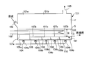
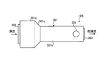
- FIG. 2 is a schematic plan view of the fluidized bed drying apparatus according to the first embodiment.
- FIG. 3 is a schematic side view of the fluidized bed drying apparatus according to the first embodiment.
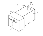
- FIG. 4 is a schematic perspective view of the fluidized bed drying apparatus according to the first embodiment.
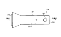
- FIG. 5 is a schematic plan view of a fluidized bed drying apparatus according to Embodiment 2 of the present invention.
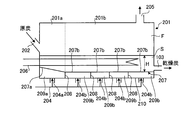
- 6 is a schematic side view of the fluidized bed drying apparatus of Example 2.
- FIG. FIG. 7 is a schematic plan view of a fluidized bed drying apparatus according to Example 3 of the present invention.
- FIG. 8 is a schematic side view of the fluidized bed drying apparatus of Example 3.
- FIG. 9 is a schematic plan view of a fluidized bed drying apparatus according to Embodiment 4 of the present invention.
- FIG. 10 is a schematic side view of the fluidized bed drying apparatus of Example 4.
- FIG. 11 is a schematic perspective view of a fluidized bed drying apparatus according to Embodiment 5 of the present invention.
- FIG. 1 is a schematic configuration diagram of a coal gasification combined power generation facility to which a fluidized bed drying apparatus according to a first embodiment of the present invention is applied.
- FIG. 2 is a schematic plan view of the fluidized bed drying apparatus according to the first embodiment. These are the schematic side views of the fluidized-bed drying apparatus of Example 1, and
- FIG. 4 is the schematic perspective view of the fluidized-bed drying apparatus of Example 1.
- the coal gasification combined power generation facility 10 includes a coal supply device 11, a fluidized bed drying device 12, a pulverized coal machine (mill) 13, a coal gasification furnace 14, and a char recovery device 15. , A gas refining device 16, a gas turbine facility 17, a steam turbine facility 18, a generator 19, and a heat recovery steam generator (HRSG) 20.
- the coal feeder 11 includes a raw coal bunker 21, a coal feeder 22, and a crusher 23.
- the raw coal bunker 21 can store low-grade coal, and can drop a predetermined amount of low-grade coal into the coal feeder 22.
- the coal feeder 22 can transport the low-grade coal dropped from the raw coal bunker 21 by a conveyor or the like and drop it on the crusher 23.
- the crusher 23 can crush the dropped low-grade coal into a predetermined size.
- the pulverized coal machine 13 is a coal pulverizer, and produces pulverized coal by pulverizing the low-grade coal (dried coal) dried by the fluidized bed dryer 12 into fine particles. That is, in the pulverized coal machine 13, the dry coal stored in the dry coal bunker 32 is dropped by the coal feeder 36, and this dry coal) is converted into low-grade coal having a predetermined particle size or less, that is, pulverized coal. .
- the pulverized coal after being pulverized by the pulverized coal machine 13 is separated from the conveying gas by the pulverized coal bag filters 37a and 37b and stored in the pulverized coal supply hoppers 38a and 38b.
- the coal gasification furnace 14 can supply pulverized coal processed by the pulverized coal machine 13 and can be recycled by returning the char (unburned coal) recovered by the char recovery device 15. .
- the coal gasification furnace 14 is connected to the compressed air supply line 41 from the gas turbine equipment 17 (compressor 61), and can supply the compressed air compressed by the gas turbine equipment 17.
- the air separation device 42 separates and generates nitrogen and oxygen from air in the atmosphere.
- a first nitrogen supply line 43 is connected to the coal gasifier 14, and a pulverized coal supply hopper is connected to the first nitrogen supply line 43.
- Charging lines 44a and 44b from 38a and 38b are connected.
- the second nitrogen supply line 45 is also connected to the coal gasification furnace 14, and the char return line 46 from the char recovery device 15 is connected to the second nitrogen supply line 45.
- the oxygen supply line 47 is connected to the compressed air supply line 41.
- nitrogen is used as a carrier gas for coal and char
- oxygen is used as an oxidant.
- the coal gasification furnace 14 is, for example, a spouted bed type gasification furnace, which combusts and gasifies coal, char, air (oxygen) supplied therein or water vapor as a gasifying agent, and produces carbon dioxide.
- a combustible gas (product gas, coal gas) containing carbon as a main component is generated, and a gasification reaction takes place using this combustible gas as a gasifying agent.
- the coal gasification furnace 14 is provided with a foreign matter removing device 48 that removes foreign matter mixed with pulverized coal.
- the coal gasification furnace 14 is not limited to the spouted bed gasification furnace, and may be a fluidized bed gasification furnace or a fixed bed gasification furnace.
- the coal gasification furnace 14 is provided with a gas generation line 49 for combustible gas toward the char recovery device 15, and can discharge combustible gas containing char.
- a gas generation line 49 for combustible gas toward the char recovery device 15, and can discharge combustible gas containing char.
- the combustible gas may be cooled to a predetermined temperature and then supplied to the char recovery device 15.
- the steam turbine facility 18 has a turbine 69 connected to the rotating shaft 64 in the gas turbine facility 17, and the generator 19 is connected to the base end portion of the rotating shaft 64.
- the exhaust heat recovery boiler 20 is provided in the exhaust gas line 70 from the gas turbine equipment 17 (the turbine 63), and generates steam by exchanging heat between the air and the high temperature exhaust gas. Therefore, the exhaust heat recovery boiler 20 is provided with the steam supply line 71 between the steam turbine equipment 18 and the turbine 69 of the steam turbine equipment 18, the steam recovery line 72 is provided, and the steam recovery line 72 is provided with the condenser 73. Yes. Therefore, in the steam turbine facility 18, the turbine 69 is driven by the steam supplied from the exhaust heat recovery boiler 20, and the generator 19 can be driven by rotating the rotating shaft 64.
- the exhaust gas from which heat has been recovered by the exhaust heat recovery boiler 20 has harmful substances removed by the gas purification device 74, and the purified exhaust gas is discharged from the chimney 75 to the atmosphere.
- raw coal low-grade coal
- the machine 22 drops the crusher 23 where it is crushed to a predetermined size.
- the crushed low-grade coal is heated and dried by the fluidized bed drying device 12, cooled by the cooler 31, and stored in the dry coal bunker 32.
- the steam taken out from the upper part of the fluidized bed drying device 12 is separated into dry coal particles by the dry coal cyclone 33 and the dry coal electrostatic precipitator 34 and compressed by the steam compressor 35 before being supplied to the fluidized bed drying device 12. Returned as drying steam.
- the dry coal particles separated from the steam are stored in the dry coal bunker 32.
- the dry coal stored in the dry coal bunker 32 is fed into the pulverized coal machine 13 by the coal feeder 36, where it is pulverized into fine particles to produce pulverized coal, and through the pulverized coal bag filters 37a and 37b. And stored in the pulverized coal supply hoppers 38a and 38b.
- the pulverized coal stored in the pulverized coal supply hoppers 38 a and 38 b is supplied to the coal gasification furnace 14 through the first nitrogen supply line 43 by nitrogen supplied from the air separation device 42.
- the char recovered by the char recovery device 15 described later is supplied to the coal gasifier 14 through the second nitrogen supply line 45 by nitrogen supplied from the air separation device 42.
- the compressed air extracted from the gas turbine equipment 17 to be described later is boosted by the booster 68 and then supplied to the coal gasification furnace 14 through the compressed air supply line 41 together with oxygen supplied from the air separation device 42.
- the supplied pulverized coal and char are combusted by compressed air (oxygen), and the pulverized coal and char are gasified to generate combustible gas (coal gas) mainly composed of carbon dioxide. Can be generated.
- the combustible gas is discharged from the coal gasifier 14 through the gas generation line 49 and sent to the char recovery device 15.
- the exhaust gas discharged from the turbine 63 in the gas turbine equipment 17 generates steam by exchanging heat with air in the exhaust heat recovery boiler 20, and supplies the generated steam to the steam turbine equipment 18. .
- the generator 69 can be driven through the rotating shaft 64 to generate electric power by driving the turbine 69 with the steam supplied from the exhaust heat recovery boiler 20.
- the drying container 101 has a hollow box shape, and is formed with a raw coal charging port 102 for charging raw coal on one end side, and on the other end side, dried charcoal for discharging a dried product obtained by heating and drying raw coal.
- a discharge port 103 is formed.
- the drying container 101 is provided with a dispersion plate 107 having a plurality of openings or ejection nozzles at a predetermined distance from the bottom plate 110 at the lower portion, and a fluidized gas (superheated steam) in the drying container 101 is provided on the bottom plate 110.
- a fluidized gas supply unit 104 is provided.
- the drying container 101 has a gas discharge port 105 for discharging the fluidized gas and the generated steam at the upper part on the dry coal discharge port 103 side.
- the drying container 101 is supplied with raw coal from the raw coal inlet 102 and supplied with fluidizing gas from the fluidizing gas supply unit 104 through the dispersion plate 107, so that a predetermined thickness is provided above the dispersion plate 107.
- a fluidized bed S is formed, and a free board portion F is formed above the fluidized bed S.
- a heat transfer pipe 106 that circulates in the fluidized bed S from the outside through the drying container 101 is disposed, and the raw coal can be heated and dried by the superheated steam flowing in the heat transfer pipe 106.
- the drying container 101 has a width on the raw coal inlet 102 side larger than a width on the dry coal outlet 103 side. That is, in this embodiment, the drying container 101 includes a preheating unit 101a provided on the raw coal input port 102 side and a drying unit 101b provided on the dry coal discharge port 103 side, and the width of the preheating unit 101a is dry. It is formed larger than the width of the portion 101b.
- the width of the drying unit 101b is W, it is desirable to set the width of the preheating unit 101a to 2W.
- the raw coal is supplied from the raw coal inlet 102 to the drying container 101 and the fluidized gas is supplied from the fluidized gas supply unit 104 through the dispersion plate 107.
- a fluidized bed S having a predetermined thickness is formed above the dispersion plate 107. The raw coal moves through the fluidized bed S to the dry coal discharge port 103 side by the fluidizing gas, and is heated and dried by receiving heat from the heat transfer tube 106 at this time.
- the raw coal moves from the raw coal inlet 102 to the dry coal outlet 103, it is heated and dried by heat from the heat transfer tube 106 or fluidized gas, but is supplied from the raw coal inlet 102.
- the preheating part 101a it is in the preheated state, and the water is hardly evaporated only by absorbing heat.
- the raw coal moves beyond the preheating region, that is, the preheating portion 101 a to the drying region, that is, the drying portion 101 b, moisture evaporation starts, gradually increases and becomes maximum, and moisture becomes closer to the dry coal discharge port 103. Evaporation is reduced.
- the drying container 101 is formed so that the width of the preheating unit 101a is larger than the width of the drying unit 101b, the raw coal having a high water content immediately after being supplied from the raw coal input port 102 is the preheating unit 101a.
- the preheating part 101a the moisture load per fluidized bed unit volume is reduced, and it is possible to receive a sufficient amount of heat from the heat transfer tube 106 and to be heated.
- the raw coal that has been preheated flows from the preheating section 101a to the drying section 101b, the raw coal is narrowed in the width direction, so that the moisture load per fluidized bed unit volume increases, but the raw coal is sufficient in the preheating section 101a. Since the temperature rises to a certain temperature, the occurrence of poor flow is suppressed, and the drying unit 101b is heated by receiving a sufficient amount of heat from the heat transfer tube 106 and the like, thereby enabling proper drying.
- the drying container 101 is set such that the height of the first dispersion plate 107a corresponding to the preheating unit 101a is higher than the height of the second dispersion plate 107b corresponding to the drying unit 101b,
- the height of the fluidized bed S in the preheating part 101a decreases. Therefore, in the preheating part 101a, the flow amount of raw coal decreases, generation
- the height of the fluidized bed S decreases, but by increasing the width of the preheating unit 101a of the drying container 101, an increase in moisture load per fluidized bed volume is suppressed.
- the drying container 101 has fluidized gas supply ports 104a and 104b formed individually for the respective wind chambers 109a and 109b provided below the fluidized bed S, the fluidized gas supply port 104a allows By increasing the amount of fluidizing gas supplied to the wind chamber 109a corresponding to the preheating unit 101a, the fluidization energy and heating amount for the raw coal in the preheating unit 101a can be increased, and preheating can be promoted.
- the dry coal from which the raw coal has been dried is discharged to the outside through the dry coal discharge port 103, and the steam generated by heating and drying the raw coal in the fluidized bed S rises together with the fluidized gas. It flows to the discharge port 103 side and is discharged from the gas discharge port 105 to the outside.
- the drying container 101 having a hollow shape, the raw coal charging port 102 for charging raw coal into one end side of the drying container 101, and the other end of the drying container 101 are provided.
- the drying vessel 101 is provided with a gas outlet 105 for discharging fluidized gas and generated steam from above the raw coal inlet 102 on one end side of the drying vessel 101, and a heat transfer tube 106 for heating the raw coal of the fluidized bed S.
- the width of the raw coal charging port 102 side is formed larger than the width of the dry coal discharging port 103 side.
- the raw coal with a large amount of water immediately after charging in the drying vessel 101 spreads in the width direction on the raw coal inlet 102 side in the drying vessel 101, the moisture load per fluidized bed volume is relaxed, and a sufficient amount of heat is generated. In response to the heat, the generation of poor flow can be suppressed and the drying efficiency of the raw coal can be improved.
- the drying container 101 is configured by a preheating unit 101a provided on the raw coal input port 102 side and a drying unit 101b provided on the dry coal discharge port 103 side, and the preheating unit
- the width of 101a is formed larger than the width of the drying unit 101b. Therefore, in the preheating part 101a, since raw coal spreads in the width direction, the moisture load per fluidized bed volume in pulverized coal with a large amount of moisture is alleviated, and sufficient heat is secured to the raw coal for heating.
- the drying section 101b although the moisture load per fluidized bed volume in the raw coal increases, the raw coal is sufficiently heated, so that the occurrence of poor flow is suppressed and the raw coal is easily removed. Can be dried.
- the fluidizing gas supply amount is different between the wind chamber 109a provided with the first dispersion plate 107a corresponding to the preheating portion 101a and the wind chamber 109b provided with the second dispersion plate 107b corresponding to the drying portion 101b. It is possible to change the amount of fluidized gas, and it is possible to supply the optimum amount of fluidized gas in accordance with the moisture content of the raw coal, to prevent the occurrence of fluidity failure and to optimize drying.
- the height of the first dispersion plate 107a is set higher than the height of the second dispersion plate 107b, so that the height of the fluidized bed S in the preheating unit 101a is high. Decrease. Therefore, in the preheating part 101a, the flow amount of raw coal decreases, generation
- the fluidized bed drying apparatus 12 ⁇ / b> A includes a drying container 201, a raw coal charging port (wet raw material charging unit) 202, and a dry coal discharging port (dry matter discharging unit). 203, a fluidizing gas supply unit 204, a gas discharge port (gas discharge unit) 205, and a heat transfer tube (heating unit) 206.
- the drying container 201 is formed so that the width on the raw coal input port 202 side is larger than the width on the dry coal discharge port 203 side. That is, in this embodiment, the drying container 201 includes a preheating unit 201a provided on the raw coal input port 202 side and a drying unit 201b provided on the dry coal discharge port 203 side, and the preheating unit 201a is the drying unit 201b. The width is narrowed toward the head and is directly connected to the drying unit 201b.
- the raw coal is supplied from the raw coal inlet 202 to the drying container 201 and the fluidizing gas is supplied from the fluidizing gas supply unit 204 through the dispersion plate 207, so that A fluidized bed S having a predetermined thickness is formed.
- the raw coal moves through the fluidized bed S to the dry matter discharge port 203 side by the fluidized gas, and is heated and dried by receiving heat from the heat transfer tube 206 at this time.
- the raw coal is heated and dried by the heat from the heat transfer tube 206 and the fluidized gas while moving from the raw coal inlet 202 to the dry matter outlet 203, but is supplied from the raw coal inlet 202.
- the preheating part 201a it is in a preheated state, and the water is hardly evaporated only by absorbing heat.
- the raw coal moves from the preheating region, that is, the preheating portion 201 a to the drying region, that is, the drying portion 201 b, moisture evaporation starts, gradually increases and becomes maximum, and moisture approaches the dry matter discharge port 203. Evaporation is reduced.
- the drying container 201 is formed so that the width of the preheating part 201a is larger than the width of the drying part 201b and narrows toward the drying part 201b.
- the raw coal that has been preheated flows from the preheating portion 201a to the drying portion 201b, it narrows in the width direction, so that the moisture load per fluidized bed unit volume increases, but the raw coal is sufficient in the preheating portion 201a. Since the temperature rises to a certain temperature, the occurrence of poor flow is suppressed, and the drying unit 201b receives a sufficient amount of heat from the heat transfer tube 206 and is heated, thereby enabling proper drying.
- the height of the first dispersion plate 207a corresponding to the preheating unit 201a is set to be higher than the height of the second dispersion plate 207b corresponding to the drying unit 201b, and toward the second dispersion plate 207b. Since the raw coal with a large amount of water is low, the height of the fluidized bed S in the preheating portion 201a is reduced. Therefore, also in this point, in the preheating part 201a, the flow amount of raw coal decreases, generation
- the fluidized bed height S decreases, but by widening the width of the preheating unit 201a of the drying vessel 201, the decrease in the fluidized bed volume is offset, and the moisture load per fluidized bed unit volume increases. Can be relaxed.
- the raw coal that has been preheated flows from the preheating unit 201a to the drying unit 201b.
- a sufficient amount of heat is supplied from the heat transfer tube 206 and the like in the drying unit 201b. By receiving and heating, proper drying becomes possible.
- the dry coal from which the raw coal has been dried is discharged to the outside through the dry matter discharge port 203, and the steam generated by heating and drying the raw coal in the fluidized bed S rises together with the fluidized gas, and the dry coal It flows to the discharge port 203 side and is discharged from the gas discharge port 205 to the outside.
- the width of the preheating unit 201a in the drying container 201 is formed larger than the width of the drying unit 201b, and the preheating unit 201a is narrowed toward the drying unit 201b. Then, it is connected to the drying unit 201b.
- the raw coal with a large amount of moisture immediately after charging in the drying container 201 spreads in the width direction on the raw coal inlet 202 side in the drying container 201, the moisture load per volume in the raw coal is relaxed, and a sufficient amount of heat is generated. In response to the heat, the occurrence of poor flow is suppressed and the drying efficiency of the raw coal can be improved. And since the width
- FIG. 7 is a schematic plan view of a fluidized bed drying apparatus according to a third embodiment of the present invention
- FIG. 8 is a schematic side view of the fluidized bed drying apparatus of the third embodiment.
- symbol is attached
- the fluidized bed drying apparatus 12B includes a drying container 301, a raw coal charging port (wet raw material charging unit) 302, and a dry coal discharging port (dry matter discharging unit). 303, a fluidizing gas supply unit 304, a gas discharge port (gas discharge unit) 305, and a heat transfer tube (heating unit) 306.
- the drying container 301 has a width on the raw coal inlet 302 side larger than a width on the dry coal outlet 303 side. That is, in the present embodiment, the drying container 301 includes a preheating unit 301a provided on the raw coal input port 302 side, a drying unit 301b provided on the dry coal discharge port 303 side, and a preheating unit 301a to the drying unit 301b. It is comprised from the reduced width part 301c to which a width
- the dispersion plate 307 includes a first dispersion plate 307a corresponding to the preheating portion 301a, a second dispersion plate 307b corresponding to the drying portion 301b, and a third dispersion plate corresponding to the reduced width portion 301c. It is divided into 307c.
- the partitioned areas of the bottom plate 310 and the dispersion plate 307 are partitioned by the partition plates 308 corresponding to the respective dispersion plates 307a, 307b, and 307c, so that the air chambers 309a, 309b, and 309c are formed.
- the fluidized gas supply sections 304a, 304b, and 304c are formed in the air chambers 309a, 309b, and 309c. Furthermore, the height of the first dispersion plate 307a corresponding to the preheating part 301a is set higher than that of the second dispersion plate 307b corresponding to the drying part 301b, and the first dispersion plate 307a and the second dispersion plate 307b are the first dispersion plate 307b.
- the first dispersion plate 307a is connected to the second dispersion plate 307b by a third dispersion plate 307c having an inclined surface inclined downward.
- the raw coal is supplied from the raw coal inlet 302 to the drying container 301 and the fluidizing gas is supplied from the fluidizing gas supply unit 304 through the dispersion plate 307, so that the upper side of the dispersion plate 307.
- a fluidized bed S having a predetermined thickness is formed.
- the raw coal moves through the fluidized bed S to the dry matter discharge port 303 side by the fluidizing gas, and is heated and dried by receiving heat from the heat transfer tube 306 at this time.
- the drying container 301 is formed so that the width of the preheating portion 301a is larger than the width of the drying portion 301b, and the reduced width portion 301c is narrowed toward the drying portion 301b.
- the raw coal with a large amount of water immediately after the addition spreads in the width direction in the preheating portion 301a. Therefore, in the preheating part 301a, the density of the raw coal is reduced, the moisture load per unit volume in the raw coal is reduced, and it is possible to be heated by receiving a sufficient amount of heat from the heat transfer tube 306 or the like. .
- the raw coal density increases in order to narrow in the width direction, and moisture per unit volume in the raw coal
- the raw coal is heated to a sufficient temperature in the preheating unit 301a, and is heated by receiving a sufficient amount of heat from the heat transfer tube 306 and the like in the drying unit 301b. It becomes possible.
- the height of the first dispersion plate 307a corresponding to the preheating portion 301a is set higher than the height of the second dispersion plate 307b corresponding to the drying portion 301b, and the third dispersion plate 307c is inclined. Therefore, the raw coal with a large amount of water reduces the height of the fluidized bed S in the preheating portion 301a. Therefore, also in this point, in the preheating part 301a, the flow rate of the raw coal is reduced, the moisture load per unit volume in the raw coal is reduced, and it is heated by receiving a sufficient amount of heat from the heat transfer tube 306 or the like. It becomes possible.
- the drying section 301b is heated by receiving a sufficient amount of heat from the heat transfer tube 306 and the like, thereby enabling proper drying.
- the dry coal from which the raw coal has been dried is discharged to the outside through the dry matter discharge port 303, and the steam generated by heating and drying the raw coal in the fluidized bed S rises together with the fluidized gas and is dried. It flows to the charcoal discharge port 303 side and is discharged from the gas discharge port 305 to the outside.
- the raw coal with a large amount of water immediately after charging in the drying container 301 spreads in the width direction on the raw coal inlet 302 side in the drying container 301, the moisture load per volume in the raw coal is relaxed, and a sufficient amount of heat is generated. It will receive and will be heated and can improve the drying efficiency of raw coal. And since the width
- FIG. 9 is a schematic plan view of a fluidized bed drying apparatus according to Example 4 of the present invention
- FIG. 10 is a schematic side view of the fluidized bed drying apparatus of Example 4.
- symbol is attached
- the fluidized bed drying apparatus 12 ⁇ / b> C includes a drying container 401, a raw coal charging port (wet raw material charging unit) 402, and a dry coal discharging port (dry matter discharging unit). 403, fluidized gas supply unit 404, gas discharge port (gas discharge unit) 405, and heat transfer tube (heating unit) 406.
- the drying container 401 has a hollow box shape, and a raw coal input port 402 is formed on one end side, and a dry coal discharge port 403 is formed on the other end side.
- the drying container 401 is provided with a dispersion plate 407 at the bottom, a fluidizing gas supply unit 404 is provided at the bottom plate 410, and a gas discharge port 405 is formed at the top on the dry coal discharge port 403 side. Therefore, the drying container 401 is supplied with raw coal from the raw coal inlet 402 and supplied with fluidizing gas from the fluidizing gas supply unit 404 through the dispersion plate 407, so that a predetermined amount is provided above the dispersion plate 407.
- a fluidized bed S having a thickness is formed, and a free board portion F is formed above the fluidized bed S.
- a heat transfer tube 406 is disposed in the fluidized bed S.
- the drying container 401 has a width on the raw coal inlet 402 side larger than a width on the dry coal outlet 403 side. That is, in this embodiment, the drying container 401 reaches the preheating unit 401a provided on the raw coal input port 402 side, the drying unit 401b provided on the dry coal discharge port 403 side, and the preheating unit 401a to the drying unit 401b. It is comprised from the reduced width part 401c to which a width
- the dispersion plate 407 is divided into a plurality of parts in the drying container 401, and a plurality of wind chambers 409 are formed by partitioning the region where the bottom plate 410 and the dispersion plate 407 are partitioned by the partition plate 408.
- the fluidizing gas supply unit 404 is connected to each wind chamber 409.
- the raw coal is supplied from the raw coal inlet 402 to the drying container 401 and the fluidizing gas is supplied from the fluidizing gas supply unit 404 through the dispersion plate 407, so that the upper side of the dispersion plate 407.
- a fluidized bed S having a predetermined thickness is formed.
- the raw coal moves through the fluidized bed S to the dry matter discharge port 403 side by the fluidizing gas, and is heated and dried by receiving heat from the heat transfer tube 406 at this time.
- the raw coal is heated and dried by the heat from the heat transfer pipe 406 and the fluidized gas while moving from the raw coal inlet 402 to the dry matter outlet 403, but is supplied from the raw coal inlet 402.
- the preheating part 401a it is in a preheated state, and the water is hardly evaporated only by absorbing heat.
- the raw coal moves from the preheating region, that is, the preheating portion 401a through the reduced width portion 401c to the drying region, that is, the drying portion 401b, water evaporation starts and gradually increases to become the maximum.
- the outlet 403 is approached, moisture evaporation decreases.
- the drying container 401 is formed so that the width of the preheating portion 401a is larger than the width of the drying portion 401b, and the reduced width portion 401c is narrowed toward the drying portion 401b.
- the raw coal with a large amount of moisture immediately after the addition spreads in the width direction in the preheating portion 401a. Therefore, in the preheating part 401a, the moisture load per fluidized bed unit volume is reduced, and it is possible to receive a sufficient amount of heat from the heat transfer tube 406 and the like and to be heated.
- the dry coal from which the raw coal has been dried is discharged to the outside through the dry matter discharge port 403, and the steam generated by heating and drying the raw coal in the fluidized bed S rises together with the fluidized gas. It flows to the discharge port 403 side and is discharged from the gas discharge port 405 to the outside.
- the width of the preheating unit 401a in the drying container 401 is formed larger than the width of the drying unit 401b, and the width is between the preheating unit 401a and the drying unit 401b.
- a narrowed width portion 401c is provided.
- the raw coal with a large amount of moisture immediately after charging in the drying container 401 spreads in the width direction on the raw coal inlet 402 side in the drying container 401, the moisture load per volume in the raw coal is relaxed, and a sufficient amount of heat is generated. In response to the heat, the occurrence of poor flow is suppressed and the drying efficiency of the raw coal can be improved. And since the width
- FIG. 11 is a schematic perspective view of a fluidized bed drying apparatus according to Example 5 of the present invention.
- symbol is attached
- the drying container 501 has a hollow box shape, and a raw coal inlet 502 is formed on one end side, and a dry coal discharge port is formed on the other end side.
- the drying container 501 is provided with a fluidizing gas supply unit, and a gas discharge port 505 is formed in the upper part. Therefore, the dry container 501 is supplied with raw coal from the raw coal inlet 502 and supplied with fluidizing gas from the fluidizing gas supply port, thereby forming a fluidized bed with a predetermined thickness.
- a free board portion is formed above the fluidized bed, and a heat transfer tube is disposed in the fluidized bed.
- the drying container 501 has a width on the raw coal inlet 502 side larger than a width on the dry coal outlet. That is, in this embodiment, the drying container 501 includes a preheating unit 501a provided on the raw coal input port 502 side and a drying unit 501b provided on the dry coal discharge port side, and the preheating unit 501a to the drying unit 501b. The width gradually decreases toward.
- the drying container 501 raw coal with a large amount of water immediately after charging spreads in the width direction in the preheating unit 501a, and preheating and drying proceed while flowing toward the drying unit 501b.
- the preheating part 501a the moisture load per fluidized bed volume is relaxed and heated by receiving a sufficient amount of heat, the occurrence of poor flow is suppressed, and the drying efficiency of raw coal can be improved.
- variety becomes narrow gradually toward the drying part 501b from the preheating part 501a, it becomes possible to make raw coal flow uniformly within the drying container 501, and in the preheating part 501a. By gradually changing the moisture load per fluidized bed volume, insufficient heat input to the raw coal can be prevented.
- the moisture per fluidized bed volume in the drying vessel 501 is determined.
- the load can be made constant, the occurrence of poor flow can be suppressed, and the drying efficiency of raw coal can be further improved.
- low grade coal was used as a wet raw material, it is applicable even if it is high grade coal, and it is not limited to coal, but can be used as a renewable biologically derived organic resource.
- thinned wood, waste wood, driftwood, grass, waste, sludge, tires, and recycled fuel (pellets and chips) reduced in weight can be used.
Landscapes
- Engineering & Computer Science (AREA)
- Life Sciences & Earth Sciences (AREA)
- Microbiology (AREA)
- Mechanical Engineering (AREA)
- General Engineering & Computer Science (AREA)
- Drying Of Solid Materials (AREA)
Abstract
Description
12,12A,12B,12C,12D 流動層乾燥装置
13 微粉炭機
14 石炭ガス化炉
15 チャー回収装置
16 ガス精製装置
17 ガスタービン設備
18 蒸気タービン設備
19 発電機
20 排熱回収ボイラ
101,201,301,401,501 乾燥容器
101a,201a,301a,401a,501a 予熱部
101b,201b,301b,401b,501b 乾燥部
102,202,302,402,502 原炭投入口(湿潤原料投入部)
103,203,303,403 乾燥炭排出口(乾燥物排出部)
104,204,304,404 流動化ガス供給部
105,205,305,405,505 ガス排出口(ガス排出部)
106,206,306,406 伝熱管(加熱部)
107,207,307,407 分散板
Claims (9)
- 中空形状をなす乾燥容器と、
該乾燥容器の一端側に湿潤原料を投入する湿潤原料投入部と、
前記乾燥容器の他端側から湿潤原料が加熱乾燥した乾燥物を排出する乾燥物排出部と、
前記乾燥容器の下部に流動化ガスを供給することで湿潤原料と共に流動層を形成する流動化ガス供給部と、
前記乾燥容器の上方から流動化ガス及び発生蒸気を排出するガス排出部と、
前記流動層の湿潤原料を加熱する加熱部と、
を備え、
前記乾燥容器は、前記湿潤原料投入部側の幅が前記乾燥物排出部側の幅より大きく形成される、
ことを特徴とする流動層乾燥装置。 - 前記乾燥容器は、前記湿潤原料投入部側に設けられる予熱部と、前記乾燥物排出部側に設けられる乾燥部とを有し、前記予熱部の幅が前記乾燥部の幅より大きく形成されることを特徴とする請求項1に記載の流動層乾燥装置。
- 前記予熱部は前記乾燥部に向けて幅が狭くなり直接前記乾燥部に連結されることを特徴とする請求項2に記載の流動層乾燥装置。
- 前記乾燥容器は、底板から所定高さをあけて多数の開口もしくは噴出ノズルを有する複数の分散板が設けられ、該複数の分散板は、前記予熱部に対応した第1分散板と、前記乾燥部に対応した第2分散板とに分割されると共にその領域が区画され、前記各分散板に対応した領域に対する前記底板に前記流動化ガス供給部がそれぞれ設けられることを特徴とする請求項2または3に記載の流動層乾燥装置。
- 前記予熱部から前記乾燥部に至る間に幅が狭くなる縮幅部が設けられていることを特徴とする請求項2から4のいずれか一つに記載の流動層乾燥装置。
- 前記乾燥装置は、前記縮幅部に対応した第3分散板を設けると共に、当該第3分散板に対応した領域に対する前記底板に前記流動化ガス供給部が設けられることを特徴とする請求項5に記載の流動層乾燥装置。
- 前記第1分散板は、前記第2分散板よりも、その高さが高く設定されることを特徴とする請求項4に記載の流動層乾燥装置。
- 前記第1分散板は前記第2分散板に向けて下方に傾斜して連結されることを特徴とする請求項7に記載の流動層乾燥装置。
- 前記第3分散板は前記第1分散板から前記第2分散板に向けて下方に傾斜して連結されることを特徴とする請求項7に記載の流動層乾燥装置。
Priority Applications (1)
| Application Number | Priority Date | Filing Date | Title |
|---|---|---|---|
| AU2012234136A AU2012234136B2 (en) | 2011-03-29 | 2012-03-22 | Fluidized bed dryer |
Applications Claiming Priority (2)
| Application Number | Priority Date | Filing Date | Title |
|---|---|---|---|
| JP2011073143A JP5693326B2 (ja) | 2011-03-29 | 2011-03-29 | 流動層乾燥装置 |
| JP2011-073143 | 2011-03-29 |
Publications (1)
| Publication Number | Publication Date |
|---|---|
| WO2012133122A1 true WO2012133122A1 (ja) | 2012-10-04 |
Family
ID=46930849
Family Applications (1)
| Application Number | Title | Priority Date | Filing Date |
|---|---|---|---|
| PCT/JP2012/057387 Ceased WO2012133122A1 (ja) | 2011-03-29 | 2012-03-22 | 流動層乾燥装置 |
Country Status (3)
| Country | Link |
|---|---|
| JP (1) | JP5693326B2 (ja) |
| AU (1) | AU2012234136B2 (ja) |
| WO (1) | WO2012133122A1 (ja) |
Citations (3)
| Publication number | Priority date | Publication date | Assignee | Title |
|---|---|---|---|---|
| JPH09194848A (ja) * | 1996-01-18 | 1997-07-29 | Nippon Steel Corp | 流動床乾燥分級機及びその操業方法 |
| WO2006044264A2 (en) * | 2004-10-12 | 2006-04-27 | Great River Energy | Apparatus for heat treatment of particulate materials |
| JP2008128524A (ja) * | 2006-11-17 | 2008-06-05 | Nippon Steel Corp | 流動乾燥方法および流動層乾燥装置 |
Family Cites Families (2)
| Publication number | Priority date | Publication date | Assignee | Title |
|---|---|---|---|---|
| US4324544A (en) * | 1980-06-12 | 1982-04-13 | Fmc Corporation | Process and system for drying coal in a fluidized bed by partial combustion |
| US4617744A (en) * | 1985-12-24 | 1986-10-21 | Shell Oil Company | Elongated slot dryer for wet particulate material |
-
2011
- 2011-03-29 JP JP2011073143A patent/JP5693326B2/ja active Active
-
2012
- 2012-03-22 AU AU2012234136A patent/AU2012234136B2/en not_active Ceased
- 2012-03-22 WO PCT/JP2012/057387 patent/WO2012133122A1/ja not_active Ceased
Patent Citations (3)
| Publication number | Priority date | Publication date | Assignee | Title |
|---|---|---|---|---|
| JPH09194848A (ja) * | 1996-01-18 | 1997-07-29 | Nippon Steel Corp | 流動床乾燥分級機及びその操業方法 |
| WO2006044264A2 (en) * | 2004-10-12 | 2006-04-27 | Great River Energy | Apparatus for heat treatment of particulate materials |
| JP2008128524A (ja) * | 2006-11-17 | 2008-06-05 | Nippon Steel Corp | 流動乾燥方法および流動層乾燥装置 |
Also Published As
| Publication number | Publication date |
|---|---|
| AU2012234136B2 (en) | 2015-07-30 |
| JP2012207839A (ja) | 2012-10-25 |
| AU2012234136A1 (en) | 2013-10-10 |
| JP5693326B2 (ja) | 2015-04-01 |
Similar Documents
| Publication | Publication Date | Title |
|---|---|---|
| JP5848014B2 (ja) | 流動層乾燥装置 | |
| JP2013108700A (ja) | 流動層乾燥装置 | |
| JP5713801B2 (ja) | 流動層乾燥装置 | |
| JP5693493B2 (ja) | 流動層乾燥装置及び石炭を用いたガス化複合発電システム | |
| WO2012147752A1 (ja) | 流動層乾燥設備及び石炭を用いたガス化複合発電システム | |
| WO2012141217A1 (ja) | 流動層乾燥装置 | |
| JP5748559B2 (ja) | 流動層乾燥装置 | |
| JP5675671B2 (ja) | 流動層乾燥装置 | |
| JP2013108699A (ja) | 流動層乾燥装置 | |
| WO2012133309A1 (ja) | 流動層乾燥装置及び流動層乾燥設備 | |
| JP5738037B2 (ja) | 流動層乾燥装置 | |
| JP5896821B2 (ja) | 流動層乾燥設備及び石炭を用いたガス化複合発電システム | |
| JP2013170767A (ja) | 流動層乾燥装置 | |
| JP5693326B2 (ja) | 流動層乾燥装置 | |
| JP5777402B2 (ja) | 流動層乾燥装置 | |
| JP2012241989A (ja) | 流動層乾燥装置 | |
| AU2013201075B2 (en) | Fluid bed drying apparatus, gasification combined power generating facility, and drying method | |
| JP5693494B2 (ja) | 流動層乾燥装置 | |
| JP5922338B2 (ja) | 流動層乾燥設備及び流動層乾燥設備を用いたガス化複合発電システム | |
| JP2012241990A (ja) | 流動層乾燥装置 | |
| JP2013167418A (ja) | 熱処理物の冷却装置 | |
| JP2013167380A (ja) | 流動層乾燥装置及び石炭を用いたガス化複合発電システム | |
| JP2012241987A (ja) | 流動層乾燥装置 | |
| JP2013174420A (ja) | 流動層乾燥装置 | |
| JP2012241991A (ja) | 流動層乾燥装置 |
Legal Events
| Date | Code | Title | Description |
|---|---|---|---|
| 121 | Ep: the epo has been informed by wipo that ep was designated in this application |
Ref document number: 12763207 Country of ref document: EP Kind code of ref document: A1 |
|
| NENP | Non-entry into the national phase |
Ref country code: DE |
|
| ENP | Entry into the national phase |
Ref document number: 2012234136 Country of ref document: AU Date of ref document: 20120322 Kind code of ref document: A |
|
| 122 | Ep: pct application non-entry in european phase |
Ref document number: 12763207 Country of ref document: EP Kind code of ref document: A1 |