WO2012133022A1 - 振動発電機 - Google Patents
振動発電機 Download PDFInfo
- Publication number
- WO2012133022A1 WO2012133022A1 PCT/JP2012/057114 JP2012057114W WO2012133022A1 WO 2012133022 A1 WO2012133022 A1 WO 2012133022A1 JP 2012057114 W JP2012057114 W JP 2012057114W WO 2012133022 A1 WO2012133022 A1 WO 2012133022A1
- Authority
- WO
- WIPO (PCT)
- Prior art keywords
- permanent magnets
- permanent magnet
- movers
- adjacent
- longitudinal direction
- Prior art date
- Legal status (The legal status is an assumption and is not a legal conclusion. Google has not performed a legal analysis and makes no representation as to the accuracy of the status listed.)
- Ceased
Links
Images




Classifications
-
- H—ELECTRICITY
- H02—GENERATION; CONVERSION OR DISTRIBUTION OF ELECTRIC POWER
- H02K—DYNAMO-ELECTRIC MACHINES
- H02K35/00—Generators with reciprocating, oscillating or vibrating coil system, magnet, armature or other part of the magnetic circuit
- H02K35/02—Generators with reciprocating, oscillating or vibrating coil system, magnet, armature or other part of the magnetic circuit with moving magnets and stationary coil systems
Definitions
- the present disclosure relates to a vibration generator that obtains electric power from a current generated by a permanent magnet reciprocatingly moving in one direction within a coil.
- an electromagnetic induction type vibration generator that obtains electric power from a current generated by a permanent magnet reciprocatingly moving in one direction in a coil is known from Patent Document 1 and the like.
- the vibration generator described in this document includes a movable magnet that moves inside a pipe.
- This movable magnet includes a plurality of magnets having the same polarity facing each other.
- the amount of power generated from the vibration power generator having the above configuration is proportional to the mass of the mover. Therefore, in order to increase the amount of power generation, it is conceivable to increase the length of the mover and further increase the number of magnets facing the same pole. At that time, the plurality of magnets constituting the movable magnet are arranged with the same poles facing each other. With this arrangement, a repulsive force acts between adjacent magnets, and each magnet receives a repulsive force so as to be displaced in a direction perpendicular to the longitudinal direction of the movable magnet.
- the movable magnet When the number of magnets constituting the movable magnet increases and the length of the movable magnet increases, the movable magnet may change to a warped shape or a wavy shape along its longitudinal direction due to the action of repulsive force. Becomes higher. When the shape of the movable magnet changes to a wavy shape or the like, the number of locations that collide with the inner wall of the pipe increases in the outer peripheral portion of the movable magnet, so that the movement of the movable magnet is hindered. This reduces the amount of power generation.
- the present disclosure has been made in order to solve the above-described problems, and by reducing a change in the shape of a mover including a plurality of permanent magnets having the same poles opposed to each other, the power generation amount can be reduced.
- An object is to provide a vibration generator that can be suppressed.
- One aspect of the present disclosure includes a hollow cylindrical member formed of a nonmagnetic material, a coil provided on the cylindrical member, and the inside of the cylindrical member along the longitudinal direction of the cylindrical member.
- Each of the plurality of movers includes a plurality of permanent magnets arranged so that the same poles face each other, and the first of the plurality of permanent magnets
- the permanent magnet is disposed on the most adjacent side of the two movable elements adjacent to each other among the plurality of movable elements, and the two first permanent magnets of the two adjacent movable elements have opposite polarities. It is characterized by being arranged like this. According to this vibration generator, the two first permanent magnets on the adjacent side of the two adjacent movers are arranged so that the different poles face each other.
- all of the plurality of permanent magnets included in each of the movers may be arranged so that the same poles as those of the adjacent permanent magnets face each other.
- all permanent magnets provided in each mover face the same polarity as the adjacent permanent magnets.
- the coil includes a plurality of divided coils, and the conductive wires of the adjacent divided coils are wound in opposite directions to each other, and a second of the plurality of permanent magnets included in the movers.
- the permanent magnet is arranged so that the same polarity as the first permanent magnet is opposed to each other, and in two adjacent movers, the end surface on the first permanent magnet side of the second permanent magnet of one mover and the other moveable
- the distance between the end face of the child second permanent magnet on the first permanent magnet side may be equal to the arrangement pitch of the plurality of divided coils.
- the distance between the end surfaces of the second permanent magnets on the first permanent magnet side is equal to the arrangement pitch of the divided coils.
- each of the movers includes a fastening member that fastens the plurality of permanent magnets, and the fastening in the longitudinal direction is performed when the fastening member fastens the plurality of permanent magnets.
- Both ends of the member may be located closer to the permanent magnet side than the end surfaces opposite to the adjacent permanent magnet side of the end surfaces of the two permanent magnets arranged at both ends of each movable element.
- the fastening member is located on the side of the permanent magnet adjacent to the end surface opposite to the side of the adjacent permanent magnet, of the end surfaces of the two permanent magnets arranged at both ends.
- the power generation amount can be increased by expanding the movable region.
- the distance between the two first permanent magnets respectively provided in the two adjacent movers decreases.
- the attractive force becomes stronger.
- the state in which the two adjacent movers are attracted to each other is reliably maintained, and the number of colliding parts is reduced, so that the reduction in the amount of power generation can be further suppressed.
- the plurality of permanent magnets included in each of the movers includes a through hole penetrating in the longitudinal direction, and are disposed at both ends of each of the movers among the plurality of permanent magnets.
- the two permanent magnets each include a concave portion that is continuous with the through hole on the end surface
- the fastening member includes a shaft portion that is inserted into the through holes of the plurality of permanent magnets, and an engaging portion that engages with the concave portion. May be provided.
- the engaging portion is located on the side of the permanent magnet adjacent to the end surface opposite to the side of the adjacent permanent magnet, of the end surfaces of the two permanent magnets arranged at both ends.
- mover in the inside of a cylindrical member expands.
- the power generation amount can be increased by expanding the movable region.
- the distance between the two first permanent magnets respectively provided in the two adjacent movers decreases.
- the attractive force becomes stronger.
- the state in which the two adjacent movers are attracted to each other is reliably maintained, and the number of colliding parts is reduced, so that the reduction in the amount of power generation can be further suppressed.
- the concave portion has a cross-sectional area larger than a cross-sectional area of the through hole in a plane perpendicular to the longitudinal direction, and is formed by two concave portions each of the two adjacent movers have.
- Grease may be provided in the area to be processed.
- the grease is provided in the region formed by the two recesses respectively provided in the two adjacent movers.
- the grease enters the end surface of the displaced first permanent magnet from the region formed by the two recesses. Due to the penetration of the grease, the two movable elements are easily moved in a direction in which the deviation between the two adjacent movable elements is reduced.
- decrease in electric power generation can be suppressed more.
- the concave portion has a cross-sectional area larger than a cross-sectional area of the through hole in a direction perpendicular to the longitudinal direction, and is formed by two concave portions respectively included in the two adjacent movers.
- a magnetic body may be provided in the region to be formed.
- the magnetic body is provided in the region formed by the two concave portions provided respectively in the two adjacent movers.
- the vibration generator includes a magnetic body having an outer diameter equal to or less than an outer diameter of the first permanent magnet between the two adjacent first permanent magnets, and the two first permanent magnets and the magnetic
- the length in the longitudinal direction with respect to the body may be equal to the arrangement pitch of the plurality of divided coils. According to this vibration generator, the magnetic flux of each first permanent magnet is attracted to the magnetic body. As a result, the state in which the two adjacent movers are attracted to each other is reliably maintained, and the number of colliding parts is reduced, so that the reduction in the amount of power generation can be further suppressed.
- grease may be provided on both end faces of the magnetic body adjacent to the two first permanent magnets of the two adjacent movers.
- this vibration power generator when the two adjacent movers are displaced in the direction perpendicular to the longitudinal direction due to the grease provided on both end faces of the magnetic body, the displacement between the two adjacent movers is reduced. Easy to move in the direction. Thereby, in the outer peripheral part of a needle
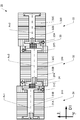
- FIG. 3 is an enlarged view showing a mover unit 30.
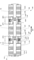
- FIG. It is an explanatory view showing the length in the longitudinal direction D1 of the permanent magnets 31A to 31C, 32A to 32D, 33A to 33C.
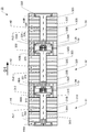
- the vibration power generator 1 includes a cylindrical member 10, a coil unit 20, a mover unit 30, and a housing 40.
- the coil unit 20 includes a plurality of coils 21.
- the mover unit 30 includes movers 31 to 33.
- the cylindrical member 10 is an example of the cylindrical member of the present disclosure.
- the hollow cylindrical member 10 having a cylindrical shape is formed from a nonmagnetic material such as ABS, POM, PC, LCP, or alumina.
- the coil unit 20 is provided on the outer peripheral surface of the cylindrical member 10.
- the conducting wire is wound on the outer peripheral surface of the cylindrical member 10 with the coil 21 adjacent to the longitudinal direction D1 of the cylindrical member 10 so that the winding directions are opposite to each other.
- the interval between adjacent coils 21 is the arrangement pitch L3.
- Each coil 21 is an example of a split coil according to the present disclosure.
- a hollow and cylindrical housing 40 is disposed outside the cylindrical member 10 and the coil unit 20 so that the cylindrical member 10 and the longitudinal direction D1 coincide with each other.
- the housing 40 is made of a magnetic material such as iron, silicon steel, permalloy, sendust, or soft ferrite.
- the mover unit 30 is disposed so as to be movable in the cylindrical member 10 along the longitudinal direction D1. That is, the mover unit 30 reciprocates within the coil unit 20.
- the mover 31 includes three permanent magnets 31A to 31C.
- the permanent magnets 31A to 31C are fixed with the same poles facing each other.
- the mover 32 includes four permanent magnets 32A to 32D. With the same poles facing each other, the permanent magnets 32A to 32D are fixed.
- the mover 33 includes three permanent magnets 33A to 33C.
- the permanent magnets 33A to 33C are fixed with the same poles facing each other.
- all the permanent magnets 31A to 31C provided in the mover 31 are arranged so that the same poles as those of the adjacent permanent magnets 31A to 31C are opposed to each other.
- the arrangement of the permanent magnets 32A to 32D and 33A to 33C provided in the mover 32 and the mover 33 is the same as the arrangement of the permanent magnets 31A to 31C provided in the mover 31.
- the two permanent magnets on the adjacent side are arranged so that the different poles face each other.
- the permanent magnet 31C is disposed so that the permanent magnet 32A and the opposite pole face each other. Due to this arrangement relationship, attractive force acts on the permanent magnet 31C and the permanent magnet 32A.
- the permanent magnet 32D is arranged so that the permanent magnet 33A and the opposite pole face each other. Due to this arrangement relationship, attractive force acts on the permanent magnet 32D and the permanent magnet 33A. Due to these two attractive forces, the movable element 31, the movable element 32, and the movable element 33 move inside the cylindrical member 10 as a single movable element unit 30.
- Each of the permanent magnets 31A to 31C, 32A to 32D, and 33A to 33C has a cylindrical shape, and is composed of a permanent magnet such as a neodymium permanent magnet or a ferrite permanent magnet.
- a permanent magnet 31C, a permanent magnet 32A, a permanent magnet 32D, and a permanent magnet 33A arranged on the most adjacent side of the two movers 31, 32, 33 adjacent to each other among the plurality of movers 31, 32, 33 are provided.
- FIG. 3 is an example of a first permanent magnet of the present disclosure.
- the permanent magnet 31B, the permanent magnet 32B, the permanent magnet 32C, and the permanent magnet 33B are examples of the second permanent magnet of the present disclosure.
- the end portions 11 and 12 in the longitudinal direction D1 of the cylindrical member 10 are sealed by the pair of sealing portions 41 and 42.
- the sealing portions 41 and 42 are press-fitted between the housing 40 and the cylindrical member 10. At the time of this press-fitting, the conductive wires from both ends of the coil unit 20 are inserted into holes (not shown) of the sealing portion 42 and connected to the circuit portion 50.
- the sealing portions 41 and 42 are made of a nonmagnetic material such as ABS, POM, PC, LCP, acrylic rubber nitrile rubber, or silicon rubber.
- the circuit unit 50 includes a rectifier circuit and a storage circuit.
- the rectifier circuit is a circuit that rectifies current generated when the mover unit 30 moves inside the cylindrical member 10.
- the storage circuit is a circuit that stores power from the current rectified by the rectifier circuit.
- Two conductors (not shown) from the storage circuit of the circuit unit 50 are combined into one cable 60.
- the circuit unit 50 is fixed inside the housing 40 while being held by a circuit holding member 51 that functions as a buffer material.
- the cable 60 is inserted through a hole formed in the center of the lid 52. Next, the lid 52 into which the cable 60 is inserted into the hole is fixed to the housing 40.
- the lid 52 is fixed to the housing 40 by screwing or a fixing method such as an adhesive.
- a connection terminal that can be inserted into an insertion port of an electronic device such as a mobile phone or an electronic book terminal is provided at the tip of the cable 60. Electric power is supplied to the electronic device from this connection terminal.
- each of the permanent magnets 31A to 31C, 32A to 32D, and 33A to 33C has a cylindrical shape and includes through holes H1 to H3 penetrating in the longitudinal direction D1.
- the permanent magnets 31A, 31C, 32A, 32D, 33A, and 33C disposed at both ends of the movers 31 to 33 include concave portions H1A, H1B, H2A, H2B, H3A, and H3B.
- the cross-sectional shape in the direction perpendicular to the longitudinal direction D1 of the through holes H1 to H3 is a circle.
- the cross-sectional shape in the direction perpendicular to the longitudinal direction D1 of the recesses H1A, H1B, H2A, H2B, H3A, and H3B is circular.
- the cross-sectional areas of the recesses H1A, H1B, H2A, H2B, H3A, and H3B in the plane perpendicular to the longitudinal direction D1 are larger than the cross-sectional areas of the through holes H1 to H3.
- the fastening member 310 includes flanges 311 and 312 and a shaft portion 313.
- the flanges 311 and 312 are provided at both ends of the shaft portion 313.
- the cross-sectional shape in the direction perpendicular to the longitudinal direction D1 of the flanges 311 and 312 is a circle.
- the shaft portion 313 has a hollow shape, and the cross-sectional shape in the direction perpendicular to the longitudinal direction D1 of the shaft portion 313 is circular.
- the flange 311 fits into the recess H1A and engages with the end surface 314 of the recess H1A in which the through hole H1 is formed.
- the flange 312 is engaged with the recess H1B and engages with the end surface 315 of the recess H1B in which the through hole H1 is formed.
- the permanent magnets 31A to 31C are caulked and fixed by the fastening member 310 by the engagement between the flange and the end surface. Since the flanges 311 and 312 are fitted in the recesses H1A and H1B, respectively, the fastening member 310 does not protrude from the permanent magnets 31A to 31C in the longitudinal direction D1.
- both ends of the fastening member 310 in the longitudinal direction D1 are end faces of the two permanent magnets 31A and 31C disposed at both ends of the mover 31. Among them, it is located on the permanent magnet 31B side from the end surface opposite to the adjacent permanent magnet 31B side.
- the fastening members 320 and 330 provided in the mover 32 and the mover 33 are the same as the fastening members 310 provided in the mover 31.
- permanent magnets 32 ⁇ / b> A to 32 ⁇ / b> D provided in the mover 32 are caulked and fixed by a fastening member 320.
- the permanent magnets 33A to 33C provided in the mover 33 are caulked and fixed by the fastening member 330. That is, the fastening members 320 and 330 have a flange and a shaft portion, similarly to the fastening member 310.
- the fitting configuration of the fastening members 320 and 330 and the permanent magnet provided in each movable element is the same as that of the fastening member 310.
- the hooks 311, 312, 321, 322, 331, and 332 are examples of the engaging portion of the present disclosure.
- the shaft portions 313, 323, and 333 are examples of the shaft portion of the present disclosure.
- each of the permanent magnets 31A to 31C is disposed so that the same polarity as that of the adjacent permanent magnets 31A to 31C is opposed, and the magnetization direction of the permanent magnets 31A to 31C is long. It faces in the direction D1.
- repulsive force acts on each of the permanent magnets 31A to 31C.
- the fastening member 310 fastens the permanent magnets 31A to 31C.
- the fastening members 310, 320, and 330 are made of a non-magnetic material such as an austenitic stainless material, an aluminum alloy material, or brass.
- the soft magnetic body 34 is disposed in a state of being attracted by a magnetic force to a region formed by the recess H1B and the recess H2A.
- the soft magnetic body 34 attracts the magnetic flux of the permanent magnet 31C and the permanent magnet 32A.
- the soft magnetic body 35 is disposed in a state of being attracted by a magnetic force to a region formed by the recess H2B and the recess H3A.
- the soft magnetic body 35 attracts the magnetic flux of the permanent magnet 32D and the permanent magnet 33A.
- the movers 31 to 33 move inside the cylindrical member 10 as a single mover unit 30 that is more integrally connected.
- the shape of the soft magnetic bodies 34, 35 in the direction perpendicular to the longitudinal direction D1 is a circle.
- the soft magnetic bodies 34 and 35 are magnetic materials such as iron, silicon steel, permalloy, sendust, and soft ferrite.
- the soft magnetic bodies 34 and 35 are examples of the magnetic body of the present disclosure.
- Grease Gr is filled in a region formed by the recess H1B and the recess H2A and a region formed by the recess H2B and the recess H3A.
- the length from the end surface 31P1 of the permanent magnet 31B on the permanent magnet 31C side to the end surface 32P2 of the permanent magnet 32B on the permanent magnet 32A side is the length L1.
- the length from the end face of the permanent magnet 32C on the permanent magnet 32D side to the end face of the permanent magnet 33B on the permanent magnet 31A side is the length L1.
- the length L1 is equal to the arrangement pitch L3 shown in FIG.
- the length L2 of each of the permanent magnets 31A, 31B, 32B, 32C, 33B, 33C in the longitudinal direction D1 is equal to the length L1.
- the length L1 is specifically the sum of the length of the permanent magnet 31C and the length of the permanent magnet 32A in the longitudinal direction D1.
- the length L1 is the sum of the lengths of the permanent magnet 32D and the permanent magnet 33A in the longitudinal direction D1.
- the permanent magnets 31A to 31C, 32A to 32D, and 33A to 33C have the same outer diameter, and the outer diameter is the outer diameter Dm.
- FIG. 4 is an enlarged view of the mover unit 130 that fastens the eight permanent magnets 131 to 138 with the same polarity facing each other with one fastening member 139. As the number of permanent magnets increases, the mover unit 130 may not be a straight straight shape. The reason why the linear shape of the mover unit 130 is damaged will be described below.
- the length of the mover unit 130 increases in parallel with the longitudinal direction D1.
- the fastening member 139 needs to be processed with a length corresponding to the length of the mover unit 130.
- the shape of the shaft portion 140 of the fastening member 139 along the longitudinal direction D1 may change to a warped shape or a wavy shape due to a problem of processing accuracy. If the shape of the shaft portion 140 along the longitudinal direction D1 is not a straight straight shape, the number of locations that collide with the cylindrical member 10 shown in FIG. 1 increases in the outer peripheral portion of the mover unit 130, and the power generation amount decreases.
- the permanent magnets 131 to 138 provided in the mover unit 130 are subjected to repulsive force by the adjacent permanent magnets 131 to 138.
- the adjacent permanent magnets 131 to 138 receive a force in a direction away from each other.
- Each of the permanent magnets 131 to 138 moves in a direction perpendicular to the longitudinal direction D1 by repulsive force.
- each of the permanent magnets 131 to 138 is displaced from each other in the direction perpendicular to the longitudinal direction D1. This amount of deviation is the difference between the diameters of the through holes of the permanent magnets 131 to 138 and the outer diameter of the shaft portion 140 of the fastening member.
- the linear shape of the mover unit 130 is impaired. Further, when the plurality of permanent magnets 131 to 138 are fastened by the fastening member 139, the permanent magnets 131 to 138 are inserted through the shaft portion 140 of the fastening member 139 to manufacture the mover unit. At the time of manufacturing, when the permanent magnets 131 to 138 are inserted through the shaft portion 140 of the fastening member 139 while receiving a repulsive force, the arrangement of the permanent magnets 131 to 138 may be shifted.
- FIG. 5 is an explanatory view showing a state in which the relative positions of the movable element 31, the movable element 32, and the movable element 33 are changed in the direction perpendicular to the longitudinal direction D1.
- the relative position is a relative position with respect to the adjacent mover in the direction perpendicular to the longitudinal direction D1.
- the direction orthogonal to the longitudinal direction D1 is the vertical direction.
- the mover 31 When the mover unit 30 moves inside the cylindrical member 10 or stops, the mover 31 may be positioned above the mover 32.
- the mover 31 moves downward and the mover 32 moves upward due to the attractive force between the permanent magnet 31C and the permanent magnet 32A.
- the mover 31 and the mover 32 move so that the distance between the permanent magnet 31C and the permanent magnet 32A is the shortest. That is, the axis Ax1 of the mover 31 moves so as to coincide with the axis Ax2 of the mover 32.
- the axial center of the mover 32 is generated by the attractive force between the permanent magnet 32D and the permanent magnet 33A.
- the permanent magnet 31C and the permanent magnet 32A are arranged so that different polarities face each other.
- attractive force acts on the two permanent magnets 31C and 32A.
- the permanent magnet 32D and the permanent magnet 33A are arranged with different polarities facing each other.
- attractive force acts on the two permanent magnets 32D and 33A. Even if the two adjacent movers are displaced from each other in the direction perpendicular to the longitudinal direction D1, the two adjacent movers are moved by this attractive force so as to reduce the magnitude of the displacement.
- all the permanent magnets 31A to 31C provided in the mover 31 are fixed so that the same poles as those of the adjacent permanent magnets 31A to 31C face each other.
- All the permanent magnets 32A to 32D provided in the mover 32 are fixed so that the same poles as those of the adjacent permanent magnets 32A to 32D face each other.
- All the permanent magnets 33A to 33C provided in the mover 33 are fixed so that the same poles as those of the adjacent permanent magnets 33A to 33C face each other.
- the magnetic fluxes of all the permanent magnets 31A to 31C, 32A to 32D, 33A to 33C provided in each of the movers 31 to 33 are directed in a direction intersecting the longitudinal direction D1.
- the magnetic flux density across the coil unit 20 is increased as compared with a vibration power generator including a mover including a permanent magnet opposed to a different pole.
- the amount of power generation can be increased by increasing the magnetic flux density.
- the length L1 is equal to the arrangement pitch L3. Due to this distance relationship, it is possible to suppress the directions of the induced electromotive currents generated in the coils 21 from canceling each other at a certain point in time when the mover unit 30 is moving inside the cylindrical member 10. By suppressing the cancellation of the induced electromotive current, it is possible to suppress a decrease in the amount of power generation.
- the fastening members 310 to 330 do not protrude from the longitudinal direction D1 in a state where at least two permanent magnets are fastened. That is, in a state where the fastening member 310 fastens the plurality of permanent magnets 31A to 31C, both ends of the fastening member 310 in the longitudinal direction D1 are the two permanent magnets 31A and 31C disposed at both ends of the mover 30. It is located on the permanent magnet 31B side from the end surface on the opposite side to the adjacent permanent magnet 31B side among the end surfaces.
- the fastening members 320 and 330 provided in the mover 32 and the mover 33 are the same as the fastening members 310 provided in the mover 31.
- mover unit 30 in the inside of the cylindrical member 10 expands.
- the power generation amount can be increased by expanding the movable region.
- the fastening members 310 to 330 do not protrude in the longitudinal direction D1, so the distance between the two first permanent magnets respectively provided in the two adjacent movers becomes shorter.
- the attractive force becomes stronger.
- the state in which the two adjacent movers are attracted to each other is reliably maintained, and the number of colliding parts is reduced, so that the reduction in the amount of power generation can be further suppressed.
- the flanges 311, 312, 321, 322, 331, 332 protrude from the end portions of the permanent magnets 31A, 31C, 32A, 32D, 33A, 33C in the longitudinal direction D1. Absent. That is, the flanges 311 and 312 are located on the side of the permanent magnet 31B adjacent to the end surface opposite to the side of the adjacent permanent magnet 31B out of the end surfaces of the two permanent magnets 31A and 31C arranged at both ends.
- the arrangement of the eaves 321, 322, 331, and 332 is the same as that of the eaves 311 and 312. Thereby, the movable area
- the power generation amount can be increased by expanding the movable region.
- the rods 311, 312, 321, 322, 331, 332 do not protrude in the longitudinal direction D 1, so the distance between the two first permanent magnets provided in the two adjacent movers decreases.
- the attractive force becomes stronger.
- the state in which the two adjacent movers are attracted to each other is reliably maintained, and the number of colliding parts is reduced, so that the reduction in the amount of power generation can be further suppressed.
- the magnetic flux of the permanent magnets 31C and 32A is attracted to the soft magnetic body 34.
- the magnetic flux of the permanent magnets 32 ⁇ / b> D and 33 ⁇ / b> A is attracted to the soft magnetic body 35.
- the grease Gr enters the end surfaces of the shifted first permanent magnets.
- the adjacent two movable elements are easily moved in the direction in which the displacement is reduced.
- the magnetic flux of the permanent magnets 31A, 31B, 32B, 32C, 33B, and 33C is attracted to the casing 40 made of a magnetic material. Since the coil unit 20 is disposed on the outer peripheral surface of the cylindrical member 10, the magnetic flux density across the coil unit 20 increases. Therefore, the amount of power generation can be improved by arranging the housing 40 outside the coil unit 20. Further, the magnetic force of the permanent magnets 31A, 31B, 32B, 32C, 33B, and 33C adversely affects components that are located outside the housing 40, such as electronic components that may cause malfunction. That can be suppressed.
- the soft magnetic body 34 is disposed in the region formed by the concave portion H1B and the concave portion H2A, and the soft magnetic body 35 is disposed in the region formed by the concave portion H2B and the concave portion H3A.
- the soft magnetic body 434 is disposed in a state where it is attracted by a magnetic force between the permanent magnet 431C and the permanent magnet 432A.
- the soft magnetic body 435 is disposed in a state of being attracted by a magnetic force between the permanent magnet 432D and the permanent magnet 433A.
- the length to the end face of the magnet 33B is the length L1.
- the length L1 is equal to the arrangement pitch L3 shown in FIG. Specifically, the length L1 is the sum of the length of the soft magnetic body 434, the length of the permanent magnet 431C, and the length of the permanent magnet 432A in the longitudinal direction D1. The length L1 is the sum of the length of the soft magnetic body 435, the length of the permanent magnet 432D, and the length of the permanent magnet 433A.
- the outer diameters of the soft magnetic bodies 4334 and 435 are not more than the outer diameter Dm of each permanent magnet.
- the soft magnetic bodies 434 and 435 attract the magnetic flux, the attractive force between the permanent magnet 431C and the permanent magnet 432A and the attractive force between the permanent magnet 432D and the permanent magnet 433A become strong.
- the movers 431 to 433 move inside the cylindrical member 10 as a single mover unit 430 that is more integrally connected.
- Grease Gr is preferably applied to both end faces in the longitudinal direction D1 of the soft magnetic bodies 434 and 435.
- the soft magnetic bodies 34 and 35 are disposed between the permanent magnets 31C and 32A and between the permanent magnets 32D and 33A, but the soft magnetic bodies 34 and 35 may not be provided.
- each of the soft magnetic bodies 434 and 435 is provided between the permanent magnets 431C and 432A and between the permanent magnets 432D and 433A, but the soft magnetic bodies 434 and 435 are not provided. Also good.
- the grease Gr is between the permanent magnets 31C and 32A, between the permanent magnets 32D and 33A, It may be provided between the permanent magnets 431C and 432A and between the permanent magnets 432D and 433A.
- the grease Gr is applied to both end faces of the soft magnetic bodies 34 and 35, but the grease Gr may not be provided.
- grease Gr is applied to both end faces of the soft magnetic bodies 434 and 435, but the grease Gr may not be provided.
- the shaft portions 313 to 333 of the fastening members 310 to 330 are inserted into the through holes H1 to H3, and the permanent magnets 31A to 31C, 32A to 32D, and 33A to 33C are fastened by the fastening members 310 to 330.
- the fastening members 310 to 330 may be a fastening member that is fastened over the outer peripheral surface of the permanent magnet, such as a second pipe provided in the vibration type electromagnetic generator described in Japanese Patent Application Laid-Open No. 2009-118581.
- the permanent magnet does not need to have a through hole and a recess.
- all the movers of the mover unit 30 are movers provided with permanent magnets facing the same polarity, but movers provided with permanent magnets facing the opposite poles without facing the same polarity. May be included. Further, the number of permanent magnets provided in each of the movers 31 to 33 may be two or more.
- the mover unit 30 is not limited to including three movers, and may include two or more movers.
- the concave portions H1A, H1B, H2A, H2B, H3A, and H3B are formed in the permanent magnets 31A, 31C, 32A, 32D, 33A, and 33C, but the present invention is not limited thereto.
- the permanent magnets 531A, 31B, 531C are each provided with a through hole H1 penetrating in the longitudinal direction D1.
- the permanent magnets 532A, 32B, 32C, 532D are each provided with a through hole H2 that penetrates in the longitudinal direction D1.
- the permanent magnets 533A, 33B, 533C are each provided with a through hole H3 penetrating in the longitudinal direction D1.
- the fastening member 510 includes flanges 511 and 512 and a shaft portion 513.
- the flange 511 engages with the end surface 514 in the longitudinal direction D1 of the permanent magnet 531A.
- the flange 512 engages with the end surface 515 in the longitudinal direction D1 of the permanent magnet 531C.
- the configuration of the fastening member 520 and the fastening member 530 is the same as the configuration of the fastening member 510.
- the length from the end surface 31P1 of the permanent magnet 31B on the permanent magnet 531C side to the end surface 32P2 of the permanent magnet 32B on the permanent magnet 532A side is the length L1.
- the length L1 is equal to the arrangement pitch L3 shown in FIG. Grease may be provided between the adjacent fastening members 510, 520, and 530.
- the concave portion is not formed in the permanent magnet provided in the mover unit 530, the manufacturing cost for forming the concave portion can be suppressed.
- a hollow soft magnetic material 534 may be disposed between the permanent magnet 531C and the permanent magnet 532A.
- the hollow soft magnetic body 535 may be disposed between the permanent magnet 532D and the permanent magnet 533A.
- the inner diameter of the soft magnetic body 534 is larger than the outer diameter of the flanges 511 and 521.
- the outer diameter of the soft magnetic body 534 is equal to or smaller than the outer diameter of the permanent magnets 531C and 532A. Further, since the mover unit 530 moves inside the cylindrical member 10 shown in FIG. 1, the inner diameter of the soft magnetic body 534 is obtained by subtracting the outer diameter of the flanges 512 and 521 from the inner diameter of the soft magnetic body 534.
- the dimensions of the soft magnetic body 535 may be the same as the dimensions of the soft magnetic body 534.
- the soft magnetic bodies 534 and 535 attract the magnetic fluxes of the permanent magnets 31C, 32A, 32D, and 33A to the soft magnetic bodies 534 and 535. Thereby, the state where two adjacent movers are attracted to each other is reliably held, and the number of colliding parts is reduced, so that a reduction in the amount of power generation can be further suppressed.
- Grease may be provided on both end surfaces of the soft magnetic bodies 534 and 535. Further, it is preferable that grease is provided in a space generated between the soft magnetic body 534 and the flanges 512 and 521 due to the difference between the inner diameter of the soft magnetic body 534 and the outer diameter of the flanges 512 and 521. Similarly to the soft magnetic body 534, the soft magnetic body 535 may be provided with grease. With this grease, when the two adjacent movers are displaced in the direction perpendicular to the longitudinal direction D1, it is easy to move in a direction in which the displacement between the two adjacent movers is reduced. Thereby, in the outer peripheral part of the needle
- the permanent magnets 31A to 31C, 32A to 32D, and 33A to 33C are fixed by caulking by the fastening members 310 to 330, respectively, but may be fixed by a known method such as adhesion with an adhesive.
- the cylindrical member 10 has a cylindrical shape, but may have a columnar shape, an elliptical column shape, or the like.
- the cross section of the through hole, the concave portion, the flange, and the shaft portion in the direction perpendicular to the longitudinal direction D1 is circular, but is not limited thereto, and may be a polygonal shape, an elliptical shape, or the like.
- the soft magnetic bodies 34, 35, 434, 435, 534, and 535 are made of a soft magnetic material.
- the soft magnetic bodies 34, 35, 434, 435, 534, and 535 are made of a permanent magnet such as a neodymium permanent magnet or a ferrite permanent magnet. May be. This permanent magnet is opposite in polarity to two adjacent permanent magnets. Permanent magnets such as neodymium-based permanent magnets and ferrite-based permanent magnets disposed between permanent magnets with different polarities facing each other are examples of the magnetic material of the present disclosure.
Landscapes
- Engineering & Computer Science (AREA)
- Power Engineering (AREA)
- Reciprocating, Oscillating Or Vibrating Motors (AREA)
- Linear Motors (AREA)
Abstract
非磁性材料から形成される中空形状の筒状部材と、筒状部材に設けられたコイルと、筒状部材の内部を、筒状部材の長手方向に沿って移動する複数の可動子と、を備え、複数の可動子の各可動子は、同極が対向するように配置された複数の永久磁石を備え、複数の永久磁石のうちの第1永久磁石は、複数の可動子のうちの互いに隣接する2つの可動子の隣接する側に配置され、隣接する2つの可動子の2つの第1永久磁石は、互いに異極が対向するように配置されること。
Description
本開示は、永久磁石がコイルの内部を一方向に往復移動することにより発生する電流から電力を得る振動発電機に関するものである。
従来から、永久磁石がコイルの内部を一方向に往復移動することにより発生する電流から電力を得る電磁誘導型の振動発電機が特許文献1などにより知られている。この文献に記載の振動発電機は、パイプの内部を移動する可動磁石を備える。この可動磁石は、同極が対向する複数の磁石を備える。
一般に上記の構成の振動発電機から得られる発電量は、可動子の質量に比例する。そのため、発電量を増加させるために、可動子の長さを長くし、さらに、同極が対向する磁石の数を増やすことが考えられる。そのとき、可動磁石を構成する複数の磁石は、同極が対向する状態で配置される。この配置により、隣接する磁石の間で斥力が作用し、各磁石が可動磁石の長手方向に垂直な方向に変位するように斥力を受ける。可動磁石を構成する磁石の数が多くなり可動磁石の長さが長くなると、可動磁石は、斥力の作用により、その長手方向に沿って、反った形状、または波打った形状に変化する可能性が高くなる。可動磁石の形状が波打った形状などに変化すると、可動磁石の外周部分においてパイプの内壁と衝突する箇所が増えるので、可動磁石の移動が阻害される。これにより、発電量が減少する。
本開示は、上述した問題点を解決するためになされたものであり、同極が対向して配置された複数の永久磁石を備える可動子の形状の変化を抑えることにより、発電量の減少を抑えることができる振動発電機を提供することを目的とする。
本開示の一側面は、非磁性材料から形成される中空形状の筒状部材と、前記筒状部材に設けられたコイルと、前記筒状部材の内部を、前記筒状部材の長手方向に沿って移動する複数の可動子と、を備え、前記複数の可動子の各可動子は、同極が対向するように配置された複数の永久磁石を備え、前記複数の永久磁石のうちの第1永久磁石は、前記複数の可動子のうちの互いに隣接する2つの可動子の最も隣接する側に配置され、前記隣接する2つの可動子の2つの第1永久磁石は、互いに異極が対向するように配置されることを特徴とするものである。この振動発電機によれば、隣接する2つの可動子の隣接する側の2つの第1永久磁石は、異極が対向するように配置される。この構成により、引力が2つの第1永久磁石に作用する。2つの第1永久磁石により引力が隣接する2つの可動子に常に作用することから、両可動子がその長手方向に垂直な方向に互いにずれたとしても、この引力により、ずれの大きさが小さくなるように隣接する2つの可動子が移動する。この結果、可動子の外周部分において、筒状部材に衝突する箇所が減少することから、発電量の減少を抑えることができる。
また、上記振動発電機において、前記各可動子が有する複数の永久磁石の全てが、隣接する永久磁石と同極が対向するように配置されてもよい。この振動発電機によれば、各可動子に備えられる全ての永久磁石は、隣接する永久磁石と同極が対向する。この同極が対向する配置により、各可動子に備えられる全ての永久磁石の磁束は長手方向に交差する方向に向く。この結果、異極が対向する永久磁石を備える可動子よりもコイルを横切る磁束密度が増加する。この磁束密度の増加により、発電量を増加させることができる。
また、上記振動発電機において、前記コイルは、複数の分割コイルからなり、隣接する前記分割コイルの導線は互いに逆方向に巻回され、前記各可動子が有する複数の永久磁石のうちの第2永久磁石は、前記第1永久磁石と同極が対向するように配置され、隣接する2つの可動子において、一方の可動子の第2永久磁石の第1永久磁石側の端面と、他方の可動子の第2永久磁石の第1永久磁石側の端面との間の距離は、前記複数の分割コイルの配置ピッチと等しくてもよい。この振動発電機によれば、隣接する2つの可動子において、それぞれの第2永久磁石の第1永久磁石側の端面間の距離は、分割コイルの配置ピッチと等しい。この距離関係により、可動子が筒状部材の内部を移動しているある時点において、各分割コイルに発生する誘導起電流の向きが互いに打ち消しあう方向となることが抑えられる。この誘導起電流の打ち消しあいが抑えられることにより、発電量の減少を抑えることができる。
また、上記振動発電機において、前記各可動子は、前記複数の永久磁石を締結する締結部材を備え、前記締結部材が前記複数の永久磁石を締結している状態において、前記長手方向における前記締結部材の両端は、前記各可動子の両端に配置される2つの永久磁石の端面のうち隣接する永久磁石側と反対側の端面よりも前記永久磁石側に位置してもよい。この振動発電機によれば、締結部材は、両端に配置される2つの永久磁石の端面のうち隣接する永久磁石側と反対側の端面よりも隣接する永久磁石側に位置する。これにより、筒状部材の内部における可動子の可動領域が拡がる。この可動領域の拡大により、発電量を増加させることができる。この発電量の増加と共に、隣接する2つの可動子にそれぞれ備えられる2つの第1永久磁石の間の距離が短くなる。両第1永久磁石が近接することにより、引力がより強くなる。この結果、隣接する2つの可動子が互いに引き合う状態が確実に保持され、衝突する箇所が減少することから、発電量の減少をより抑えることができる。
また、上記振動発電機において、前記各可動子が有する複数の永久磁石は、前記長手方向に貫通する貫通孔をそれぞれ備え、前記複数の永久磁石のうち、前記各可動子の両端に配置される2つの永久磁石は、前記貫通孔に連続する凹部を端面にそれぞれ備え、前記締結部材は、前記複数の永久磁石の貫通孔に挿通される軸部と、前記凹部に係合する係合部とを備えてもよい。この振動発電機によれば、係合部は、両端に配置される2つの永久磁石の端面のうち隣接する永久磁石側と反対側の端面よりも隣接する永久磁石側に位置する。これにより、筒状部材の内部における可動子の可動領域が拡がる。この可動領域の拡大により、発電量を増加させることができる。この発電量の増加と共に、隣接する2つの可動子にそれぞれ備えられる2つの第1永久磁石の間の距離が短くなる。両第1永久磁石が近接することにより、引力がより強くなる。この結果、隣接する2つの可動子が互いに引き合う状態が確実に保持され、衝突する箇所が減少することから、発電量の減少をより抑えることができる。
また、上記振動発電機において、前記凹部は、前記長手方向に垂直な面における前記貫通孔の断面積よりも大きな断面積を有し、前記隣接する2つの可動子がそれぞれ有する2つの凹部により形成される領域に、グリスが設けられてもよい。この振動発電機によれば、隣接する2つの可動子がそれぞれ備える2つの凹部により形成される領域にグリスが設けられる。隣接する2つの可動子が長手方向に直交する方向にずれた場合に、グリスが、2つの凹部により形成される領域から、ずれた第1永久磁石の端面に浸入する。このグリスの浸入により、2つの可動子は、隣接する2つの可動子のずれが小さくなる方向に移動しやすくなる。これにより、可動子の外周部分において、筒状部材に衝突する箇所がより減少することから、発電量の減少をより抑えることができる。
また、上記振動発電機において、前記凹部は、前記長手方向に垂直な方向における前記貫通孔の断面積よりも大きな断面積を有し、前記隣接する2つの可動子がそれぞれ有する2つの凹部により形成される領域に、磁性体が設けられてもよい。この振動発電機によれば、隣接する2つの可動子がそれぞれ備える2つの凹部により形成される領域に磁性体が備えられる。これにより、各第1永久磁石の磁束が磁性体に引き寄せられる。この結果、隣接する2つの可動子が互いに引き合う状態が確実に保持され、衝突する箇所が減少することから、発電量の減少をより抑えることができる。
また、上記振動発電機は、前記隣接する2つの第1永久磁石の間に、その第1永久磁石の外径以下の外径を有する磁性体を備え、前記2つの第1永久磁石と前記磁性体との前記長手方向の長さは、前記複数の分割コイルの配置ピッチと等しくてもよい。この振動発電機によれば、各第1永久磁石の磁束が磁性体に引き寄せられる。この結果、隣接する2つの可動子が互いに引き合う状態が確実に保持され、衝突する箇所が減少することから、発電量の減少をより抑えることができる。
また、上記振動発電機において、前記隣接する2つの可動子の2つの第1永久磁石に隣接する前記磁性体の両端面に、グリスが設けられてもよい。この振動発電機によれば、磁性体の両端面に設けられたグリスにより、隣接する2つの可動子が長手方向に直交する方向にずれた場合に、隣接する2つの可動子のずれが小さくなる方向に移動しやすくなる。これにより、可動子の外周部分において、筒状部材に衝突する箇所がより減少することから、発電量の減少をより抑えることができる。
(実施形態)
本開示の一実施形態について、図1を参照して説明する。図1に示すように、振動発電機1は、円筒部材10と、コイルユニット20と、可動子ユニット30と、筐体40とを備える。コイルユニット20は複数のコイル21を備える。可動子ユニット30は可動子31~33を備える。円筒部材10が本開示の筒状部材の一例である。
本開示の一実施形態について、図1を参照して説明する。図1に示すように、振動発電機1は、円筒部材10と、コイルユニット20と、可動子ユニット30と、筐体40とを備える。コイルユニット20は複数のコイル21を備える。可動子ユニット30は可動子31~33を備える。円筒部材10が本開示の筒状部材の一例である。
中空で円筒形状の円筒部材10は、ABS、POM、PC、LCP、アルミナなどの非磁性材料から形成される。コイルユニット20が円筒部材10の外周面に備えられる。導線が、円筒部材10の外周面において、円筒部材10の長手方向D1に隣り合うコイル21と互いに巻回方向が逆方向になるように巻回される。隣り合うコイル21の間隔は配置ピッチL3である。各コイル21が本開示の分割コイルの一例である。
中空で円筒形状の筐体40が、円筒部材10、及びコイルユニット20の外側に円筒部材10と長手方向D1を一致させて配置される。筐体40は、鉄、ケイ素鋼、パーマロイ、センダスト、ソフトフェライトなどの磁性材料からなる。
可動子ユニット30が円筒部材10の内部を長手方向D1に沿って移動可能に配置される。すなわち、可動子ユニット30は、コイルユニット20の内部を往復移動する。可動子31は、3つの永久磁石31A~31Cを備える。同極が対向した状態で、永久磁石31A~31Cが固定される。可動子32は、4つの永久磁石32A~32Dを備える。同極が対向した状態で、永久磁石32A~32Dが固定される。可動子33は、3つの永久磁石33A~33Cを備える。同極が対向した状態で、永久磁石33A~33Cが固定される。すなわち、可動子31に備えられる全ての永久磁石31A~31Cは、隣接する永久磁石31A~31Cと同極が対向して配置される。可動子32、および可動子33に備えられる永久磁石32A~32D、33A~33Cの配置関係は、可動子31に備えられる永久磁石31A~31Cの配置関係と同様である。
隣接する2つの可動子の各可動子において、隣接する側の2つの永久磁石は、異極が対向するように配置される。具体的には、隣接する2つの可動子31、32において、永久磁石31Cは、永久磁石32Aと異極が対向するように配置される。この配置関係により、引力が永久磁石31Cと永久磁石32Aとに作用する。隣接する2つの可動子32、33において、永久磁石32Dは、永久磁石33Aと異極が対向するように配置される。この配置関係により、引力が永久磁石32Dと永久磁石33Aとに作用する。この2箇所の引力により、可動子31と可動子32と可動子33とは、単一の可動子ユニット30として円筒部材10の内部を移動する。
永久磁石31A~31C、32A~32D、33A~33Cの各々は、円筒形状を有し、ネオジム系の永久磁石、フェライト系の永久磁石などの永久磁石から構成される。可動子ユニット30の詳細な構成は後述する。複数の可動子31、32、33のうちの互いに隣接する2つの可動子31、32、33の最も隣接する側に配置される永久磁石31C、永久磁石32A、永久磁石32D、および永久磁石33Aが、本開示の第1永久磁石の一例である。永久磁石31B、永久磁石32B、永久磁石32C、および永久磁石33Bが本開示の第2永久磁石の一例である。
可動子ユニット30が円筒部材10の内部に配置された状態で、円筒部材10の長手方向D1の端部11、12が一対の封止部41、42により封じられる。封止部41、42は筐体40と円筒部材10との間に圧入される。この圧入時、コイルユニット20の両端からの導線は封止部42の図示しない孔に挿入され、回路部50に接続される。この封止部41、42はABS、POM、PC、LCP、アクリルゴムニトリルゴム、シリコンゴムなどの非磁性材料から形成される。
回路部50は、整流回路と蓄電回路とを含む。整流回路は、可動子ユニット30が円筒部材10の内部を移動することにより発生する電流を整流する回路である。蓄電回路は整流回路により整流された電流から電力を蓄電する回路である。回路部50の蓄電回路からの図示しない2本の導線は1本のケーブル60にまとめられる。回路部50が、緩衝材として機能する回路保持部材51により保持された状態で、筐体40の内部に固定される。ケーブル60が蓋52の中央に形成された孔に挿通される。次に、ケーブル60が孔に挿通された蓋52が筐体40に固定される。この蓋52は、螺子螺合、または接着剤などの固定方法で筐体40と固定される。このケーブル60の先端に携帯電話、電子書籍端末などの電子機器の差込口に差込可能な接続端子が設けられる。この接続端子から、電子機器に電力が供給される。
可動子ユニット30の構成を、図2、および図3を参照して説明する。図2に示すように、永久磁石31A~31C、32A~32D、33A~33Cの各々は、円筒形状を有し、長手方向D1に貫通する貫通孔H1~H3をそれぞれ備える。長手方向D1において、可動子31~33の両端に配置される永久磁石31A、31C、32A、32D、33A、33Cは、凹部H1A、H1B、H2A、H2B、H3A、H3Bを備える。
貫通孔H1~H3の長手方向D1に垂直な方向の断面形状は円形である。凹部H1A、H1B、H2A、H2B、H3A、H3Bの長手方向D1に垂直な方向の断面形状は円形である。凹部H1A、H1B、H2A、H2B、H3A、H3Bの長手方向D1に垂直な面における断面積は、貫通孔H1~H3の断面積よりも大きい。
締結部材310は、鍔311、312と軸部313とを備える。鍔311、312は、軸部313の両端に備えられる。鍔311、312の長手方向D1に垂直な方向の断面形状は、円形である。軸部313は中空形状を有し、軸部313の長手方向D1に垂直な方向の断面形状は、円形である。鍔311が、凹部H1Aに嵌合し、貫通孔H1が形成される凹部H1Aの端面314に係合する。鍔312が、凹部H1Bに嵌合し、貫通孔H1が形成される凹部H1Bの端面315に係合する。この鍔と端面との係合により、永久磁石31A~31Cは締結部材310によりかしめ固定される。鍔311、312が、それぞれ凹部H1A、H1Bに嵌合するので、締結部材310は、永久磁石31A~31Cから長手方向D1に、はみ出さない。すなわち、締結部材310が複数の永久磁石31A~31Cを締結している状態において、長手方向D1における締結部材310の両端は、可動子31の両端に配置される2つの永久磁石31A、31Cの端面のうち隣接する永久磁石31B側と反対側の端面よりも永久磁石31B側に位置する。可動子32、および可動子33に備えられる締結部材320、330も可動子31に備えられる締結部材310と同様である。可動子31と同様に、可動子32に備えられる永久磁石32A~32Dが締結部材320によりかしめ固定される。可動子33に備えられる永久磁石33A~33Cが締結部材330によりかしめ固定される。すなわち、締結部材320、330は、締結部材310と同様に、鍔および軸部を有する。締結部材320、330と各可動子に備えられる永久磁石との嵌合構成は、締結部材310と同様である。鍔311、312、321、322、331、332が本開示の係合部の一例である。軸部313、323、333が本開示の軸部の一例である。
永久磁石31A~31Cが固定された状態では、永久磁石31A~31Cの各々は、隣接する永久磁石31A~31Cと同極が対向するように配置され、永久磁石31A~31Cの着磁方向は長手方向D1に向く。同極が対向する状態で永久磁石31A~31Cが配置されると、斥力が永久磁石31A~31Cの各々に働く。この斥力が永久磁石31A~31Cの各々に働いている状態において、締結部材310は永久磁石31A~31Cを締結する。同極が対向するように永久磁石31A~31Cが配置されると、永久磁石31A~31Cのそれぞれの磁束が長手方向D1に対して交差する方向に向くので、図1に示すコイルユニット20を横切る磁束密度が増加する。可動子32、33に備えられる永久磁石32A~32D、33A~33Cも、可動子31に備えられる永久磁石31A~31Cと同様に配置されるので、コイルユニット20を横切る磁束密度が増加する。締結部材310、320、330はオーステナイト系ステンレス材料、アルミ合金材料、真鍮などの非磁性材料から形成される。
軟磁性体34が凹部H1Bと凹部H2Aとにより形成された領域に磁力により吸着された状態で配置される。軟磁性体34は、永久磁石31C、および永久磁石32Aの磁束を引き寄せる。軟磁性体35が凹部H2Bと凹部H3Aとにより形成された領域に磁力により吸着された状態で配置される。軟磁性体35は、永久磁石32D、および永久磁石33Aの磁束を引き寄せる。軟磁性体34、35が磁束を引き寄せることにより、永久磁石31Cと永久磁石32Aとの間の引力、および永久磁石32Dと永久磁石33Aとの間の引力が強くなる。引力が強くなることにより、可動子31~33は、より一体的に連結される単一の可動子ユニット30として円筒部材10の内部を移動する。軟磁性体34、35の長手方向D1に垂直な方向の形状は、円形である。軟磁性体34、35は、鉄、ケイ素鋼、パーマロイ、センダスト、ソフトフェライトなどの磁性材料である。軟磁性体34、35が本開示の磁性体の一例である。
グリスGrが凹部H1Bと凹部H2Aとにより形成された領域、および凹部H2Bと凹部H3Aとにより形成された領域に充填される。
図3に示すように、長手方向D1において、永久磁石31C側の永久磁石31Bの端面31P1から永久磁石32A側の永久磁石32Bの端面32P2までの長さは、長さL1である。長手方向D1において、永久磁石32D側の永久磁石32Cの端面から永久磁石31A側の永久磁石33Bの端面までの長さは長さL1である。長さL1は、図1に示す配置ピッチL3と等しい。長手方向D1における永久磁石31A、31B、32B、32C、33B、33Cの各々の長さL2は、長さL1と等しい。また、長さL1は、具体的に、長手方向D1における永久磁石31Cの長さと永久磁石32Aの長さの和である。長さL1は、長手方向D1における永久磁石32Dと永久磁石33Aとの長さの和である。永久磁石31A~31C、32A~32D、33A~33Cの各々の外径は等しく、その外径は、外径Dmである。
図4は、同極が対向する8つの永久磁石131~138を1つの締結部材139で締結する可動子ユニット130の拡大図である。永久磁石の数が増えるほど、可動子ユニット130が、直線状のまっすぐな形状でなくなるおそれがある。以下に、可動子ユニット130の直線形状が損なわれる理由を説明する。
可動子ユニット130に備えられる永久磁石の数が増えるにつれて、長手方向D1に平行に可動子ユニット130の長さが長くなる。この長尺化に伴い、締結部材139は可動子ユニット130の長さに対応する長さで加工される必要がある。締結部材139が長くなると、加工精度の問題により、長手方向D1に沿う締結部材139の軸部140の形状が、反った形状、または波打った形状に変化するおそれがある。長手方向D1に沿う軸部140の形状が直線状のまっすぐな形状でないと、可動子ユニット130の外周部分において、図1に示す円筒部材10に衝突する箇所が増加し、発電量が減少する。
可動子ユニット130に備えられる永久磁石131~138は、隣接する永久磁石131~138により斥力を受ける。この斥力により、隣接する永久磁石131~138は、互いに遠ざかる方向に力を受ける。永久磁石131~138の各々は、斥力により、長手方向D1に垂直な方向へ移動する。この移動の結果、永久磁石131~138の各々が長手方向D1に垂直な方向に互いにずれる。このずれる量は、永久磁石131~138の貫通孔の径と締結部材の軸部140の外径との差である。このずれにより、可動子ユニット130の直線形状が損なわれる。また、複数の永久磁石131~138を締結部材139により締結するとき、締結部材139の軸部140に永久磁石131~138を挿通させて、可動子ユニット130を製造する。この製造時において、この締結部材139の軸部140に永久磁石131~138が斥力をうけながら挿通されたときに、永久磁石131~138の配置がずれるおそれがある。すなわち、軸部140の形状が変化しなくても、永久磁石131~138の貫通孔の径と締結部材の軸部140の外径との差だけずれるおそれがある。永久磁石131~138の配置がずれると、可動子ユニット130の外周部分において、図1に示す円筒部材10に衝突する箇所が増加する。
図3、および図5を参照して、本実施形態の可動子ユニット30の動作について説明する。図5は可動子31、可動子32、および可動子33が、長手方向D1に垂直な方向において、相対位置が変化した状態を示す説明図である。相対位置は、長手方向D1に垂直な方向において、隣接する可動子に対する相対的な位置である。図5において、長手方向D1に直交する方向が上下方向である。
可動子ユニット30が円筒部材10の内部を移動するとき、または停止しているときに、可動子31が可動子32に対して上側に位置する可能性がある。この両可動子の相対位置が変化した場合、永久磁石31Cと永久磁石32Aとの間の引力により、可動子31は下側へ移動し、可動子32は上側へ移動する。可動子31と可動子32とは、永久磁石31Cと永久磁石32Aとの距離が最も短くなるように移動する。すなわち、可動子31の軸心Ax1が、可動子32の軸心Ax2と一致するように移動する。この可動子31、32の移動と同様に、可動子32と可動子33との相対位置が変化したときにも、永久磁石32Dと永久磁石33Aとの間の引力により、可動子32の軸心Ax2と可動子33の軸心Ax3が一致するように移動する。従って、可動子31~33の長手方向D1に垂直な方向への移動により、可動子ユニット30の長手方向に垂直な方向への変形が抑えられる。
[実施形態の効果]
本実施形態の振動発電機1によれば、永久磁石31Cと永久磁石32Aとは、異極が対向して配置される。この構成により、引力が2つの永久磁石31C、32Aに作用する。永久磁石32Dと永久磁石33Aとは、異極が対向して配置される。この構成により、引力が2つの永久磁石32D、33Aに作用する。隣接する2つの可動子が、長手方向D1に垂直な方向に互いにずれたとしても、この引力により、ずれの大きさが小さくなるように隣接する2つの可動子が移動する。この結果、隣接する2つの可動子が独立に円筒部材10の内部を移動するよりも、可動子31~33の外周部分において、円筒部材10に衝突する箇所が減少する。この衝突箇所の減少により、発電量の減少を抑えることができる。
本実施形態の振動発電機1によれば、永久磁石31Cと永久磁石32Aとは、異極が対向して配置される。この構成により、引力が2つの永久磁石31C、32Aに作用する。永久磁石32Dと永久磁石33Aとは、異極が対向して配置される。この構成により、引力が2つの永久磁石32D、33Aに作用する。隣接する2つの可動子が、長手方向D1に垂直な方向に互いにずれたとしても、この引力により、ずれの大きさが小さくなるように隣接する2つの可動子が移動する。この結果、隣接する2つの可動子が独立に円筒部材10の内部を移動するよりも、可動子31~33の外周部分において、円筒部材10に衝突する箇所が減少する。この衝突箇所の減少により、発電量の減少を抑えることができる。
本実施形態の振動発電機1によれば、可動子31に備えられる全ての永久磁石31A~31Cは、隣接する永久磁石31A~31Cと同極が対向して固定される。可動子32に備えられる全ての永久磁石32A~32Dは、隣接する永久磁石32A~32Dと同極が対向して固定される。可動子33に備えられる全ての永久磁石33A~33Cは、隣接する永久磁石33A~33Cと同極が対向して固定される。これにより、可動子31~33の各々に備えられる全ての永久磁石31A~31C、32A~32D、33A~33Cの磁束は長手方向D1に交差する方向に向く。この結果、異極が対向する永久磁石を備える可動子を備える振動発電機よりもコイルユニット20を横切る磁束密度が増加する。この磁束密度の増加により、発電量を増加させることができる。
本実施形態の振動発電機1によれば、長さL1は、配置ピッチL3と等しい。この距離関係により、可動子ユニット30が円筒部材10の内部を移動しているある時点において、各コイル21に発生する誘導起電流の向きが互いに打ち消しあう方向となることが抑えられる。この誘導起電流の打ち消しあいが抑えられることにより、発電量の減少を抑えることができる。
本実施形態の振動発電機1によれば、締結部材310~330は、少なくとも2つの永久磁石を締結した状態において、長手方向D1に対し、はみ出さない。すなわち、締結部材310が、複数の永久磁石31A~31Cを締結している状態において、長手方向D1における締結部材310の両端は、可動子30の両端に配置される2つの永久磁石31A、31Cの端面のうち隣接する永久磁石31B側と反対側の端面よりも永久磁石31B側に位置する。可動子32、および可動子33に備えられる締結部材320、330も可動子31に備えられる締結部材310と同様である。これにより、円筒部材10の内部における可動子ユニット30の可動領域が拡がる。この可動領域の拡大により、発電量を増加させることができる。この発電量の増加と共に、締結部材310~330が長手方向D1に、はみ出さないので、隣接する2つの可動子にそれぞれ備えられる2つの第1永久磁石の距離が短くなる。両第1永久磁石が互いに近接することにより、引力がより強くなる。この結果、隣接する2つの可動子が互いに引き合う状態が確実に保持され、衝突する箇所が減少することから、発電量の減少をより抑えることができる。
本実施形態の振動発電機1によれば、鍔311、312、321、322、331、332は、長手方向D1に、永久磁石31A、31C、32A、32D、33A、33Cの端部からはみ出さない。すなわち、鍔311、312は、両端に配置される2つの永久磁石31A、31Cの端面のうち隣接する永久磁石31B側と反対側の端面よりも隣接する永久磁石31B側に位置する。鍔321、322、331、332の配置も、鍔311、312と同様である。これにより、円筒部材10の内部における可動子ユニット30の可動領域が拡がる。この可動領域の拡大により、発電量を増加させることができる。この発電量の増加と共に、鍔311、312、321、322、331、332が長手方向D1にはみ出さないので、隣接する2つの可動子に備えられる両第1永久磁石の距離が短くなる。両第1永久磁石が互いに近接することにより、引力がより強くなる。この結果、隣接する2つの可動子が互いに引き合う状態が確実に保持され、衝突する箇所が減少することから、発電量の減少をより抑えることができる。
本実施形態の振動発電機1によれば、永久磁石31C、32Aの磁束が軟磁性体34に引き寄せられる。永久磁石32D、33Aの磁束が軟磁性体35に引き寄せられる。これにより、隣接する2つの可動子が互いに引き合う状態が確実に保持され、衝突する箇所が減少することから、発電量の減少をより抑えることができる。
本実施形態の振動発電機1によれば、ずれた両第1永久磁石の端面にグリスGrが侵入する。このグリスGrの侵入により、隣接する2つの可動子が長手方向に直交する方向にずれた場合に、隣接する2つの可動子のずれが小さくなる方向に移動しやすくなる。これにより、可動子の直線形状が保たれ、可動子30の外周部分において円筒部材10に衝突する箇所が減少することから、発電量の減少を抑えることができる。
永久磁石31A、31B、32B、32C,33B,33Cの磁束は、磁性材料からなる筐体40に引き寄せられる。コイルユニット20が円筒部材10の外周面に配置されるので、コイルユニット20を横切る磁束密度は増加する。従って、筐体40がコイルユニット20の外側に配置されることにより、発電量を向上させることができる。また、永久磁石31A、31B、32B、32C,33B,33Cの磁力が、筐体40の外側に位置する部品、例えば電子部品など磁力の影響により誤作動を起こす可能性がある部品に悪影響を及ぼすことを抑えることができる。
[変形例1]
本実施形態では、軟磁性体34が凹部H1Bと凹部H2Aとにより形成された領域に配置され、軟磁性体35が凹部H2Bと凹部H3Aとにより形成された領域に配置されたが、これに限られない。図6に示すように、軟磁性体434が、永久磁石431Cと永久磁石432Aとの間に磁力により吸着された状態で配置される。軟磁性体435が、永久磁石432Dと永久磁石433Aとの間に磁力により吸着された状態で配置される。長手方向D1において、永久磁石431C側の永久磁石31B側の端面から永久磁石432A側の永久磁石32Bの端面までの長さ、および永久磁石432D側の永久磁石32Cの端面から永久磁石431A側の永久磁石33Bの端面までの長さは長さL1である。長さL1は、図1に示す配置ピッチL3と等しい。具体的に、長さL1は、長手方向D1において、軟磁性体434の長さと永久磁石431Cの長さと永久磁石432Aの長さとの和である。長さL1は、軟磁性体435の長さと永久磁石432Dの長さと永久磁石433Aの長さとの和である。軟磁性体4334、435の外径は、各永久磁石の外径Dm以下である。軟磁性体434、435が磁束を引き寄せることにより、永久磁石431Cと永久磁石432Aとの間の引力、および永久磁石432Dと永久磁石433Aとの間の引力が強くなる。引力が強くなることにより、可動子431~433は、より一体的に連結される単一の可動子ユニット430として円筒部材10の内部を移動する。
本実施形態では、軟磁性体34が凹部H1Bと凹部H2Aとにより形成された領域に配置され、軟磁性体35が凹部H2Bと凹部H3Aとにより形成された領域に配置されたが、これに限られない。図6に示すように、軟磁性体434が、永久磁石431Cと永久磁石432Aとの間に磁力により吸着された状態で配置される。軟磁性体435が、永久磁石432Dと永久磁石433Aとの間に磁力により吸着された状態で配置される。長手方向D1において、永久磁石431C側の永久磁石31B側の端面から永久磁石432A側の永久磁石32Bの端面までの長さ、および永久磁石432D側の永久磁石32Cの端面から永久磁石431A側の永久磁石33Bの端面までの長さは長さL1である。長さL1は、図1に示す配置ピッチL3と等しい。具体的に、長さL1は、長手方向D1において、軟磁性体434の長さと永久磁石431Cの長さと永久磁石432Aの長さとの和である。長さL1は、軟磁性体435の長さと永久磁石432Dの長さと永久磁石433Aの長さとの和である。軟磁性体4334、435の外径は、各永久磁石の外径Dm以下である。軟磁性体434、435が磁束を引き寄せることにより、永久磁石431Cと永久磁石432Aとの間の引力、および永久磁石432Dと永久磁石433Aとの間の引力が強くなる。引力が強くなることにより、可動子431~433は、より一体的に連結される単一の可動子ユニット430として円筒部材10の内部を移動する。
グリスGrが軟磁性体434、435の長手方向D1における両端面に塗られることが好ましい。グリスGrが軟磁性体434、435の両端面に塗られることにより、隣接する2つの可動子が長手方向に直交する方向にずれた場合に、隣接する2つの可動子のずれが小さくなる方向に移動しやすくなる。これにより、可動子ユニット430の外周部分において円筒部材10に衝突する箇所が減少することから、発電量の減少を抑えることができる。
[変形例2]
本実施形態では、軟磁性体34、35が永久磁石31C、32Aの間、および永久磁石32D、33Aの間に配置されたが、軟磁性体34、35は備えられなくてもよい。また、変形例1において、軟磁性体434、435のそれぞれが、永久磁石431C、432Aの間、および永久磁石432D、433Aの間に設けられたが、軟磁性体434、435は設けられなくてもよい。本実施形態、および変形例1において、軟磁性体34、35、および軟磁性体434、435が設けられない場合、グリスGrが、永久磁石31C、32Aの間、永久磁石32D、33Aの間、永久磁石431C、432Aの間、および永久磁石432D、433Aの間、に設けられてもよい。
本実施形態では、軟磁性体34、35が永久磁石31C、32Aの間、および永久磁石32D、33Aの間に配置されたが、軟磁性体34、35は備えられなくてもよい。また、変形例1において、軟磁性体434、435のそれぞれが、永久磁石431C、432Aの間、および永久磁石432D、433Aの間に設けられたが、軟磁性体434、435は設けられなくてもよい。本実施形態、および変形例1において、軟磁性体34、35、および軟磁性体434、435が設けられない場合、グリスGrが、永久磁石31C、32Aの間、永久磁石32D、33Aの間、永久磁石431C、432Aの間、および永久磁石432D、433Aの間、に設けられてもよい。
[変形例3]
本実施形態では、軟磁性体34、35の両端面にグリスGrが塗られたが、グリスGrは設けられなくてもよい。変形例1では、軟磁性体434、435の両端面にグリスGrが塗られたが、グリスGrは設けられなくてもよい。
本実施形態では、軟磁性体34、35の両端面にグリスGrが塗られたが、グリスGrは設けられなくてもよい。変形例1では、軟磁性体434、435の両端面にグリスGrが塗られたが、グリスGrは設けられなくてもよい。
[変形例4]
本実施形態では、締結部材310~330の軸部313~333が貫通孔H1~H3に挿通されて、永久磁石31A~31C、32A~32D、33A~33Cが締結部材310~330により締結されたが、この構成に限られない。特開2009-118581号公報に記載の振動型電磁発電機に備えられる第2のパイプのように、永久磁石の外周面にわたって締結する締結部材であってもよい。この場合、永久磁石は貫通孔、および凹部を備える必要は無い。
本実施形態では、締結部材310~330の軸部313~333が貫通孔H1~H3に挿通されて、永久磁石31A~31C、32A~32D、33A~33Cが締結部材310~330により締結されたが、この構成に限られない。特開2009-118581号公報に記載の振動型電磁発電機に備えられる第2のパイプのように、永久磁石の外周面にわたって締結する締結部材であってもよい。この場合、永久磁石は貫通孔、および凹部を備える必要は無い。
[変形例5]
本実施形態では、可動子ユニット30の全ての可動子は、同極が対向する永久磁石を備える可動子であるが、同極が対向せず、異極が対向する永久磁石を備える可動子を含んでもよい。また、可動子31~33の各々に備えられる永久磁石の数は、2つ以上であればよい。また、可動子ユニット30は3つの可動子を備えることに限られず、2つ以上の可動子を備えてもよい。
本実施形態では、可動子ユニット30の全ての可動子は、同極が対向する永久磁石を備える可動子であるが、同極が対向せず、異極が対向する永久磁石を備える可動子を含んでもよい。また、可動子31~33の各々に備えられる永久磁石の数は、2つ以上であればよい。また、可動子ユニット30は3つの可動子を備えることに限られず、2つ以上の可動子を備えてもよい。
[変形例6]
本実施形態では、凹部H1A、H1B、H2A、H2B、H3A、H3Bが永久磁石31A、31C、32A、32D、33A、33Cに形成されたが、これに限られない。図7に示すように、永久磁石531A、31B、531Cは、長手方向D1に貫通する貫通孔H1をそれぞれ備える。永久磁石532A、32B、32C、532Dは、長手方向D1に貫通する貫通孔H2をそれぞれ備える。永久磁石533A、33B、533Cは、長手方向D1に貫通する貫通孔H3をそれぞれ備える。締結部材510は鍔511、512と軸部513とを備える。鍔511は、永久磁石531Aの長手方向D1の端面514に係合する。鍔512は、永久磁石531Cの長手方向D1の端面515に係合する。締結部材520、および締結部材530の構成も締結部材510の構成と同様である。永久磁石531C側の永久磁石31Bの端面31P1から永久磁石532A側の永久磁石32Bの端面32P2までの長さは、長さL1である。長さL1は、図1に示す配置ピッチL3と等しい。隣接する締結部材510、520、530の間にグリスが設けられるとよい。
本実施形態では、凹部H1A、H1B、H2A、H2B、H3A、H3Bが永久磁石31A、31C、32A、32D、33A、33Cに形成されたが、これに限られない。図7に示すように、永久磁石531A、31B、531Cは、長手方向D1に貫通する貫通孔H1をそれぞれ備える。永久磁石532A、32B、32C、532Dは、長手方向D1に貫通する貫通孔H2をそれぞれ備える。永久磁石533A、33B、533Cは、長手方向D1に貫通する貫通孔H3をそれぞれ備える。締結部材510は鍔511、512と軸部513とを備える。鍔511は、永久磁石531Aの長手方向D1の端面514に係合する。鍔512は、永久磁石531Cの長手方向D1の端面515に係合する。締結部材520、および締結部材530の構成も締結部材510の構成と同様である。永久磁石531C側の永久磁石31Bの端面31P1から永久磁石532A側の永久磁石32Bの端面32P2までの長さは、長さL1である。長さL1は、図1に示す配置ピッチL3と等しい。隣接する締結部材510、520、530の間にグリスが設けられるとよい。
可動子ユニット530に備えられる永久磁石に凹部が形成されないので、凹部を形成する製造コストを抑えることができる。
中空形状の軟磁性体534が、永久磁石531Cと永久磁石532Aとの間に配置されてもよい。中空形状の軟磁性体535が、永久磁石532Dと永久磁石533Aとの間に配置されてもよい。軟磁性体534の内径は、鍔511、521の外径よりも大きい。軟磁性体534の外径は、永久磁石531C、532Aの外径以下である。また可動子ユニット530は図1に示す円筒部材10の内部を移動するので、軟磁性体534の内径は、軟磁性体534の内径から鍔512、521の外径を差し引いた値が、円筒部材10の内径から永久磁石の外径を差し引いた値以下になるように設定されればよい。軟磁性体535の寸法は軟磁性体534の寸法と同じであればよい。この軟磁性体534、535により永久磁石31C、32A、32D、33Aの磁束が軟磁性体534、535に引き寄せられる。これにより、隣接する2つの可動子が互いに引き合う状態が確実に保持され、衝突する箇所が減少することから、発電量の減少をより抑えることができる。
軟磁性体534、535の両端面に、グリスが設けられるとよい。また、軟磁性体534の内径と鍔512、521の外径との差により、軟磁性体534と鍔512、521との間に生じるスペースにグリスが設けられるとよい。軟磁性体535も軟磁性体534と同様にグリスが設けられるとよい。このグリスにより、隣接する2つの可動子が長手方向D1に直交する方向にずれた場合に、隣接する2つの可動子のずれが小さくなる方向に移動しやすくなる。これにより、可動子ユニット530の外周部分において、円筒部材10に衝突する箇所がより減少することから、発電量の減少をより抑えることができる。
[変形例7]
本実施形態では、永久磁石31A~31C、32A~32D、33A~33Cは、締結部材310~330により、それぞれかしめ固定されたが、接着剤による接着などの周知の方法で固定されてもよい。
本実施形態では、永久磁石31A~31C、32A~32D、33A~33Cは、締結部材310~330により、それぞれかしめ固定されたが、接着剤による接着などの周知の方法で固定されてもよい。
[変形例8]
本実施形態、および変形例では、円筒部材10は、円筒形状であったが、柱状、楕円柱などの形状であってもよい。また貫通孔、凹部、鍔、軸部の長手方向D1に垂直な方向の断面は、円形であったが、これにかぎられず、多角形、楕円などの形状でもよい。
本実施形態、および変形例では、円筒部材10は、円筒形状であったが、柱状、楕円柱などの形状であってもよい。また貫通孔、凹部、鍔、軸部の長手方向D1に垂直な方向の断面は、円形であったが、これにかぎられず、多角形、楕円などの形状でもよい。
[変形例9]
本実施形態、および変形例において、永久磁石31Bと永久磁石31Cとの間、永久磁石32Bと永久磁石32Cとの間、永久磁石32Cと永久磁石32Dとの間、永久磁石33Aと永久磁石33Bとの間、に緩衝材が設けられてもよい。緩衝材が設けられる場合であっても、長手方向D1において、永久磁石31C側の永久磁石31Bの端面31P1から永久磁石32A側の永久磁石32Bの端面32P2までの長さは、長さL1である。長手方向D1において、永久磁石32D側の永久磁石32Cの端面から永久磁石31A側の永久磁石33Bの端面までの長さは長さL1である。長さL1は、図1に示す配置ピッチL3と等しい。
本実施形態、および変形例において、永久磁石31Bと永久磁石31Cとの間、永久磁石32Bと永久磁石32Cとの間、永久磁石32Cと永久磁石32Dとの間、永久磁石33Aと永久磁石33Bとの間、に緩衝材が設けられてもよい。緩衝材が設けられる場合であっても、長手方向D1において、永久磁石31C側の永久磁石31Bの端面31P1から永久磁石32A側の永久磁石32Bの端面32P2までの長さは、長さL1である。長手方向D1において、永久磁石32D側の永久磁石32Cの端面から永久磁石31A側の永久磁石33Bの端面までの長さは長さL1である。長さL1は、図1に示す配置ピッチL3と等しい。
[変形例10]
本実施形態、および変形例において、軟磁性体34、35、434、435、534、535は軟磁性材料から構成されたが、ネオジム系の永久磁石、フェライト系の永久磁石などの永久磁石から構成されてもよい。この永久磁石は隣接する2つの永久磁石と異極が対向する。異極が対向する永久磁石の間に配置されるネオジム系の永久磁石、フェライト系の永久磁石などの永久磁石が本開示の磁性材料の一例である。
本実施形態、および変形例において、軟磁性体34、35、434、435、534、535は軟磁性材料から構成されたが、ネオジム系の永久磁石、フェライト系の永久磁石などの永久磁石から構成されてもよい。この永久磁石は隣接する2つの永久磁石と異極が対向する。異極が対向する永久磁石の間に配置されるネオジム系の永久磁石、フェライト系の永久磁石などの永久磁石が本開示の磁性材料の一例である。
10 円筒部材
20 コイルユニット
21 コイル
30、130、430、530 可動子ユニット
31、32、33 可動子
310、320、330 締結部材
311、312、321、322、331、332 鍔
313、323、333 軸部
31A、32B、31C 永久磁石
32A、32B、32C、32D 永久磁石
33A、32B、33C 永久磁石
34、35 軟磁性体
314、315、324、325、334、335 端面
40 筐体
50 回路部
Ax1、Ax2、Ax3 軸心
Gr グリス
H1、H2、H3 貫通孔
H1A、H1B、H2A、H2B、H3A、H3B 凹部
L3 配置ピッチ
Dm 外径
20 コイルユニット
21 コイル
30、130、430、530 可動子ユニット
31、32、33 可動子
310、320、330 締結部材
311、312、321、322、331、332 鍔
313、323、333 軸部
31A、32B、31C 永久磁石
32A、32B、32C、32D 永久磁石
33A、32B、33C 永久磁石
34、35 軟磁性体
314、315、324、325、334、335 端面
40 筐体
50 回路部
Ax1、Ax2、Ax3 軸心
Gr グリス
H1、H2、H3 貫通孔
H1A、H1B、H2A、H2B、H3A、H3B 凹部
L3 配置ピッチ
Dm 外径
Claims (9)
- 非磁性材料から形成される中空形状の筒状部材と、
前記筒状部材に設けられたコイルと、
前記筒状部材の内部を、前記筒状部材の長手方向に沿って移動する複数の可動子と、
を備え、
前記複数の可動子の各可動子は、同極が対向するように配置された複数の永久磁石を備え、
前記複数の永久磁石のうちの第1永久磁石は、前記複数の可動子のうちの互いに隣接する2つの可動子の最も隣接する側に配置され、
前記隣接する2つの可動子の2つの第1永久磁石は、互いに異極が対向するように配置されること
を特徴とする振動発電機。 - 前記各可動子が有する複数の永久磁石の全てが、隣接する永久磁石と同極が対向するように配置されること
を特徴とする請求項1に記載の振動発電機。 - 前記コイルは、複数の分割コイルからなり、
隣接する前記分割コイルの導線は互いに逆方向に巻回され、
前記各可動子が有する複数の永久磁石のうちの第2永久磁石は、前記第1永久磁石と同極が対向するように配置され、
隣接する2つの可動子において、一方の可動子の第2永久磁石の第1永久磁石側の端面と、他方の可動子の第2永久磁石の第1永久磁石側の端面との間の距離は、前記複数の分割コイルの配置ピッチと等しいこと
を特徴とする請求項2に記載の振動発電機。 - 前記各可動子は、前記複数の永久磁石を締結する締結部材を備え、
前記締結部材が前記複数の永久磁石を締結している状態において、前記長手方向における前記締結部材の両端は、前記各可動子の両端に配置される2つの永久磁石の端面のうち隣接する永久磁石側と反対側の端面よりも前記永久磁石側に位置すること
を特徴とする請求項3に記載の振動発電機。 - 前記各可動子が有する複数の永久磁石は、前記長手方向に貫通する貫通孔をそれぞれ備え、
前記複数の永久磁石のうち、前記各可動子の両端に配置される2つの永久磁石は、前記貫通孔に連続する凹部を端面にそれぞれ備え、
前記締結部材は、前記複数の永久磁石の貫通孔に挿通される軸部と、前記凹部に係合する係合部とを備えること
を特徴とする請求項4に記載の振動発電機。 - 前記凹部は、前記長手方向に垂直な面における前記貫通孔の断面積よりも大きな断面積を有し、
前記隣接する2つの可動子がそれぞれ有する2つの凹部により形成される領域に、グリスが設けられること
を特徴とする請求項5に記載の振動発電機。 - 前記凹部は、前記長手方向に垂直な面における前記貫通孔の断面積よりも大きな断面積を有し、
前記隣接する2つの可動子がそれぞれ有する2つの凹部により形成される領域に、磁性体が設けられること
を特徴とする請求項5に記載の振動発電機。 - 前記隣接する2つの第1永久磁石の間に、その第1永久磁石の外径以下の外径を有する磁性体を備え、
前記2つの第1永久磁石と前記磁性体との前記長手方向の長さは、前記複数の分割コイルの配置ピッチと等しいこと
を特徴とする請求項1に記載の振動発電機。 - 前記隣接する2つの可動子の2つの第1永久磁石に隣接する前記磁性体の両端面に、グリスが設けられること
を特徴とする請求項8に記載の振動発電機。
Applications Claiming Priority (2)
| Application Number | Priority Date | Filing Date | Title |
|---|---|---|---|
| JP2011-071615 | 2011-03-29 | ||
| JP2011071615A JP2012209996A (ja) | 2011-03-29 | 2011-03-29 | 振動発電機 |
Publications (1)
| Publication Number | Publication Date |
|---|---|
| WO2012133022A1 true WO2012133022A1 (ja) | 2012-10-04 |
Family
ID=46930753
Family Applications (1)
| Application Number | Title | Priority Date | Filing Date |
|---|---|---|---|
| PCT/JP2012/057114 Ceased WO2012133022A1 (ja) | 2011-03-29 | 2012-03-21 | 振動発電機 |
Country Status (2)
| Country | Link |
|---|---|
| JP (1) | JP2012209996A (ja) |
| WO (1) | WO2012133022A1 (ja) |
Citations (2)
| Publication number | Priority date | Publication date | Assignee | Title |
|---|---|---|---|---|
| JP2005518774A (ja) * | 2002-02-19 | 2005-06-23 | ロックウェル・サイエンティフィック・ライセンシング・エルエルシー | 動的磁石システム |
| JP2009213194A (ja) * | 2008-02-29 | 2009-09-17 | Sumida Corporation | 振動型電磁発電機 |
-
2011
- 2011-03-29 JP JP2011071615A patent/JP2012209996A/ja not_active Withdrawn
-
2012
- 2012-03-21 WO PCT/JP2012/057114 patent/WO2012133022A1/ja not_active Ceased
Patent Citations (2)
| Publication number | Priority date | Publication date | Assignee | Title |
|---|---|---|---|---|
| JP2005518774A (ja) * | 2002-02-19 | 2005-06-23 | ロックウェル・サイエンティフィック・ライセンシング・エルエルシー | 動的磁石システム |
| JP2009213194A (ja) * | 2008-02-29 | 2009-09-17 | Sumida Corporation | 振動型電磁発電機 |
Also Published As
| Publication number | Publication date |
|---|---|
| JP2012209996A (ja) | 2012-10-25 |
Similar Documents
| Publication | Publication Date | Title |
|---|---|---|
| US9318942B2 (en) | Electric machine with linear mover | |
| EP2346149A1 (en) | Linear actuator | |
| JP4841673B2 (ja) | 電磁石アクチュエータ | |
| JP2012039824A (ja) | 振動発電機 | |
| JPWO2009035050A1 (ja) | リニアモータ及びリニアモータのコギング低減方法 | |
| JP2010041761A (ja) | リニアモータ | |
| JP2010158140A (ja) | リニアモータ | |
| US8120225B2 (en) | External split field generator | |
| JP5553064B2 (ja) | 振動発電機 | |
| JPWO2024029117A5 (ja) | ||
| JP2012205450A (ja) | 振動発電機 | |
| JP5589507B2 (ja) | リニア駆動装置の可動子及び固定子 | |
| JP2012209996A (ja) | 振動発電機 | |
| WO2013038591A1 (ja) | 受電装置、送電装置および電力伝送装置 | |
| JP2013031277A (ja) | 振動発電機 | |
| JP2000166211A (ja) | ボイスコイル形リニアモータ | |
| JP2012019613A (ja) | リニアモータ | |
| JP5370697B2 (ja) | リニアモータ | |
| JP2012100407A (ja) | リニアアクチュエータ | |
| WO2023042639A1 (ja) | ロータの製造装置 | |
| CN115280654B (zh) | 可动件及线性伺服电动机 | |
| JP2011172391A (ja) | 振動発電機 | |
| RU2543512C1 (ru) | Линейный электродвигатель | |
| EP3637600A1 (en) | Tubular linear motor | |
| JP2009268330A (ja) | コアレスモータ |
Legal Events
| Date | Code | Title | Description |
|---|---|---|---|
| 121 | Ep: the epo has been informed by wipo that ep was designated in this application |
Ref document number: 12762890 Country of ref document: EP Kind code of ref document: A1 |
|
| NENP | Non-entry into the national phase |
Ref country code: DE |
|
| 122 | Ep: pct application non-entry in european phase |
Ref document number: 12762890 Country of ref document: EP Kind code of ref document: A1 |