WO2012132604A1 - 酸素濃縮装置用酸素タンクユニット - Google Patents
酸素濃縮装置用酸素タンクユニット Download PDFInfo
- Publication number
- WO2012132604A1 WO2012132604A1 PCT/JP2012/053620 JP2012053620W WO2012132604A1 WO 2012132604 A1 WO2012132604 A1 WO 2012132604A1 JP 2012053620 W JP2012053620 W JP 2012053620W WO 2012132604 A1 WO2012132604 A1 WO 2012132604A1
- Authority
- WO
- WIPO (PCT)
- Prior art keywords
- oxygen
- oxygen tank
- pressure
- valve
- nitrogen adsorption
- Prior art date
- Legal status (The legal status is an assumption and is not a legal conclusion. Google has not performed a legal analysis and makes no representation as to the accuracy of the status listed.)
- Ceased
Links
Images


Classifications
-
- A—HUMAN NECESSITIES
- A61—MEDICAL OR VETERINARY SCIENCE; HYGIENE
- A61M—DEVICES FOR INTRODUCING MEDIA INTO, OR ONTO, THE BODY; DEVICES FOR TRANSDUCING BODY MEDIA OR FOR TAKING MEDIA FROM THE BODY; DEVICES FOR PRODUCING OR ENDING SLEEP OR STUPOR
- A61M16/00—Devices for influencing the respiratory system of patients by gas treatment, e.g. ventilators; Tracheal tubes
- A61M16/10—Preparation of respiratory gases or vapours
-
- B—PERFORMING OPERATIONS; TRANSPORTING
- B01—PHYSICAL OR CHEMICAL PROCESSES OR APPARATUS IN GENERAL
- B01D—SEPARATION
- B01D53/00—Separation of gases or vapours; Recovering vapours of volatile solvents from gases; Chemical or biological purification of waste gases, e.g. engine exhaust gases, smoke, fumes, flue gases, aerosols
- B01D53/02—Separation of gases or vapours; Recovering vapours of volatile solvents from gases; Chemical or biological purification of waste gases, e.g. engine exhaust gases, smoke, fumes, flue gases, aerosols by adsorption, e.g. preparative gas chromatography
- B01D53/04—Separation of gases or vapours; Recovering vapours of volatile solvents from gases; Chemical or biological purification of waste gases, e.g. engine exhaust gases, smoke, fumes, flue gases, aerosols by adsorption, e.g. preparative gas chromatography with stationary adsorbents
- B01D53/047—Pressure swing adsorption
- B01D53/053—Pressure swing adsorption with storage or buffer vessel
-
- A—HUMAN NECESSITIES
- A61—MEDICAL OR VETERINARY SCIENCE; HYGIENE
- A61M—DEVICES FOR INTRODUCING MEDIA INTO, OR ONTO, THE BODY; DEVICES FOR TRANSDUCING BODY MEDIA OR FOR TAKING MEDIA FROM THE BODY; DEVICES FOR PRODUCING OR ENDING SLEEP OR STUPOR
- A61M16/00—Devices for influencing the respiratory system of patients by gas treatment, e.g. ventilators; Tracheal tubes
- A61M16/10—Preparation of respiratory gases or vapours
- A61M16/1005—Preparation of respiratory gases or vapours with O2 features or with parameter measurement
- A61M16/101—Preparation of respiratory gases or vapours with O2 features or with parameter measurement using an oxygen concentrator
-
- A—HUMAN NECESSITIES
- A61—MEDICAL OR VETERINARY SCIENCE; HYGIENE
- A61M—DEVICES FOR INTRODUCING MEDIA INTO, OR ONTO, THE BODY; DEVICES FOR TRANSDUCING BODY MEDIA OR FOR TAKING MEDIA FROM THE BODY; DEVICES FOR PRODUCING OR ENDING SLEEP OR STUPOR
- A61M16/00—Devices for influencing the respiratory system of patients by gas treatment, e.g. ventilators; Tracheal tubes
- A61M16/10—Preparation of respiratory gases or vapours
- A61M16/105—Filters
- A61M16/1055—Filters bacterial
-
- A—HUMAN NECESSITIES
- A61—MEDICAL OR VETERINARY SCIENCE; HYGIENE
- A61M—DEVICES FOR INTRODUCING MEDIA INTO, OR ONTO, THE BODY; DEVICES FOR TRANSDUCING BODY MEDIA OR FOR TAKING MEDIA FROM THE BODY; DEVICES FOR PRODUCING OR ENDING SLEEP OR STUPOR
- A61M16/00—Devices for influencing the respiratory system of patients by gas treatment, e.g. ventilators; Tracheal tubes
- A61M16/10—Preparation of respiratory gases or vapours
- A61M16/105—Filters
- A61M16/106—Filters in a path
- A61M16/107—Filters in a path in the inspiratory path
-
- A—HUMAN NECESSITIES
- A61—MEDICAL OR VETERINARY SCIENCE; HYGIENE
- A61M—DEVICES FOR INTRODUCING MEDIA INTO, OR ONTO, THE BODY; DEVICES FOR TRANSDUCING BODY MEDIA OR FOR TAKING MEDIA FROM THE BODY; DEVICES FOR PRODUCING OR ENDING SLEEP OR STUPOR
- A61M16/00—Devices for influencing the respiratory system of patients by gas treatment, e.g. ventilators; Tracheal tubes
- A61M16/10—Preparation of respiratory gases or vapours
- A61M16/1005—Preparation of respiratory gases or vapours with O2 features or with parameter measurement
- A61M2016/102—Measuring a parameter of the content of the delivered gas
- A61M2016/1025—Measuring a parameter of the content of the delivered gas the O2 concentration
-
- B—PERFORMING OPERATIONS; TRANSPORTING
- B01—PHYSICAL OR CHEMICAL PROCESSES OR APPARATUS IN GENERAL
- B01D—SEPARATION
- B01D2253/00—Adsorbents used in seperation treatment of gases and vapours
- B01D2253/10—Inorganic adsorbents
- B01D2253/106—Silica or silicates
- B01D2253/108—Zeolites
-
- B—PERFORMING OPERATIONS; TRANSPORTING
- B01—PHYSICAL OR CHEMICAL PROCESSES OR APPARATUS IN GENERAL
- B01D—SEPARATION
- B01D2256/00—Main component in the product gas stream after treatment
- B01D2256/12—Oxygen
-
- B—PERFORMING OPERATIONS; TRANSPORTING
- B01—PHYSICAL OR CHEMICAL PROCESSES OR APPARATUS IN GENERAL
- B01D—SEPARATION
- B01D2257/00—Components to be removed
- B01D2257/10—Single element gases other than halogens
- B01D2257/102—Nitrogen
-
- B—PERFORMING OPERATIONS; TRANSPORTING
- B01—PHYSICAL OR CHEMICAL PROCESSES OR APPARATUS IN GENERAL
- B01D—SEPARATION
- B01D2259/00—Type of treatment
- B01D2259/40—Further details for adsorption processes and devices
- B01D2259/402—Further details for adsorption processes and devices using two beds
-
- B—PERFORMING OPERATIONS; TRANSPORTING
- B01—PHYSICAL OR CHEMICAL PROCESSES OR APPARATUS IN GENERAL
- B01D—SEPARATION
- B01D2259/00—Type of treatment
- B01D2259/45—Gas separation or purification devices adapted for specific applications
- B01D2259/4533—Gas separation or purification devices adapted for specific applications for medical purposes
Definitions
- the present invention relates to an oxygen tank unit used in a medical oxygen concentrator.
- an oxygen concentrator that produces oxygen by using an adsorbent (generally zeolite) that selectively adsorbs nitrogen from air has been put to practical use.
- an adsorbent generally zeolite
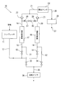
- FIG. 10 shows a general piping system diagram of such an oxygen concentrator 10.
- the compressed air compressed by the compressor 11 is supplied to the inlets of the pair of nitrogen adsorption vessels 17 and 18 through the pipelines 12, 13 and 14 and the pressure switching valves (electromagnetic on-off valves) 15 and 16.
- the outlets of the nitrogen adsorption vessels 17 and 18 are connected to a single oxygen tank 24 via the pipelines 19, 20 and 21 and the check valves 22 and 23, and the oxygen tank 24 includes a pipeline 25 and a pressure reducing valve. It is connected to the air outlet 27 via a (regulator) 26.
- the nitrogen adsorption containers 17 and 18 are filled therein with, for example, zeolite (powder or particles) as a nitrogen adsorbent which selectively adsorbs nitrogen in the air.
- the check valves 22 and 23 are one-way valves that allow gas (air) flow from the nitrogen adsorption vessels 17 and 18 to the oxygen tank 24 and do not allow gas flow in the opposite direction.
- the pipelines 31 and 32 are connected to the pipelines 13 and 14 on the downstream side of the pressure switching valves 15 and 16 (the inlet side of the nitrogen adsorption vessels 17 and 18), respectively.
- the pressure reducing switching valves (electromagnetic on-off valves) 33 and 34 are provided respectively.
- the outlet sides of the pressure reduction switching valves 33 and 34 join at a pipe 35 and are connected to the exhaust muffler 36.
- the lines 19 and 20 are connected by a line 37 on the upstream side of the check valves 22 and 23 (the outlet side of the nitrogen adsorption vessels 17 and 18), and the line 37 is provided with a throttle valve (orifice) 38. , 39 are disposed the purge valve 40.
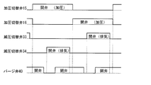
- the pressurization switching valves 15, 16, the pressure reduction switching valves 33, 34 and the purge valve 40 are controlled to open and close as shown in the time chart shown in FIG. That is, when the pressure switching valve 15 (16) is opened, the pressure switching valve 16 (15) is closed, and after the pressure switching valve 15 (16) is opened and a predetermined time has elapsed, the pressure reducing valve 34 (33) opens.
- the pressure switching valve 16 (15) is closed when the pressure switching valve 15 (16) is opened, the compressed air from the compressor 11 is sent only to the nitrogen adsorption container 17 (18), and the nitrogen adsorption container 17 (18) The nitrogen in the air is adsorbed on the adsorbent in the), and a high concentration of oxygen is sent to the conduit 19 (20).
- the check valve 22 (23) is opened to store high concentration oxygen in the oxygen tank 24.
- the pressure reducing switching valve 34 (33) opens, and when a fixed time after the pressure reducing switching valve 34 (33) opens, the purge valve 40 opens. Therefore, high concentration oxygen on the high pressure side is supplied from the upstream side to the nitrogen adsorption vessel 18 (17) on the side where the pressure is low, and flows back to the nitrogen adsorption vessel 18 (17). Therefore, the nitrogen adsorbed on the adsorbent in the nitrogen adsorption vessel 18 (17) is released to the pipe 32 (31) together with the high concentration air, and the gas containing the released nitrogen is the pipe 35 and the exhaust muffler 36. Exhausted through.
- the high concentration oxygen stored in the oxygen tank 24 is depressurized by the pressure reducing valve (regulator) 26, and then supplied to the patient from the air outlet 27. That is, since the pressure in the oxygen tank 24 largely fluctuates as a result of the high pressure high concentration oxygen being supplied alternately from the nitrogen adsorption vessels 17 and 18, the high pressure oxygen whose pressure fluctuation is reduced by the pressure reducing valve 26 is Supply to the patient.
- the above is the operation principle of the oxygen concentrator 10.
- the oxygen concentrator 10 that operates on the above principle of operation includes the compressor 11, the pressure switching valves 15, 16, the pressure reducing valves 33, 34, the check valves 22, 23, the purge valve 40, the oxygen tank 24, the pressure reducing valve 26, etc. It takes a lot of pipelines to connect with each other, resulting in upsizing of the entire apparatus and an increase in assembly cost.
- the present invention can simplify and unitize the configuration around the oxygen tank 24, the check valves 22 and 23, and the pressure reducing valve 26, paying particular attention to the configuration around the oxygen tank 24 among the oxygen concentrators 10 of the above operating principle.
- An object of the present invention is to obtain an oxygen tank unit for an oxygen concentrator.
- the present invention comprises a single oxygen tank body connected to a pair of nitrogen adsorption vessels alternately receiving a supply of compressed air; and the nitrogen adsorption interposed between the oxygen tank body and the pair of nitrogen adsorption vessels.
- the oxygen concentrator having a check valve which permits gas flow from the container to the oxygen tank body but not the opposite gas flow; and a pressure reducing valve having an oxygen outlet connected to the oxygen tank body, the reverse It is characterized in that at least one of a pair of nitrogen adsorption container connecting cylindrical bodies provided with a stop valve and a pressure reducing valve is directly attached to the wall surface of the oxygen tank to make an oxygen tank unit for an oxygen concentrator.
- a bacteria filter unit can be further connected to the outlet of the pressure reducing valve of the oxygen tank body.
- the oxygen tank body may further be provided with at least one of an oxygen pressure sensor and an oxygen concentration sensor.
- the oxygen concentration sensor is preferably provided on the outlet side of the pressure reducing valve.
- a pair of nitrogen adsorption vessel connecting cylinders provided with a check valve and a check valve unit inserted in a stepped through hole portion of the oxygen tank main body wall are coaxially stacked on the check valve unit It can consist of a fixed nitrogen adsorption vessel connection pipe.
- the pressure reducing valve is disposed between the primary pressure introducing passage communicating with the through hole of the oxygen tank main body, the secondary pressure extracting passage, and the primary pressure introducing passage and the secondary pressure extracting passage.
- a main housing disposed on the wall of the oxygen tank body, and a main housing coupled to the main housing and supporting the actuating diaphragm assembly between the main housing and the secondary pressure outlet
- a sub-housing defining a secondary pressure chamber in communication with the passage, the actuating diaphragm assembly and the main valve interlocking to open and close the main valve in response to pressure fluctuations in the secondary pressure chamber .
- the lower housing of the bacteria filter unit in communication with the secondary pressure extraction passage is fixed to the main housing of the pressure reducing valve, and the bacteria filter is sandwiched between the lower housing and the lower housing.
- the upper housing can be fixed.
- the main housing of the pressure reducing valve may, in one aspect, be removably supported on the oxygen tank body via a bayonet pawl.
- the oxygen concentrator using a pair of nitrogen adsorption containers at least one of the pair of nitrogen adsorption container connecting cylindrical bodies provided with a check valve and the pressure reducing valve is directly attached to the oxygen tank main body wall,
- the configurations of the oxygen tank body, the check valve and the pressure reducing valve can be simplified and made into a unit.
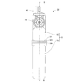
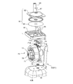
- FIG. 1 is a perspective view of an embodiment of an oxygen tank unit according to the invention for use in an oxygen concentrator.
- FIG. FIG. 3 is a cross-sectional view taken along the line III-III in FIG. It is the IV section enlarged view of FIG. It is a disassembled perspective view of FIG. 4 part. It is the VI section enlarged view of FIG. It is a disassembled perspective view of FIG. 6 part
- FIG. 2 is a circuit diagram of an oxygen tank unit according to the present invention.
- FIG. 6 is an exploded perspective view of the main part showing another embodiment of the oxygen tank unit according to the present invention. It is a circuit diagram of the oxygen concentration device which the present invention presupposes. It is a timing chart which shows the opening and closing timing of each valve of the oxygen concentrator of FIG.
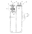
- FIGS. 1 to 8 show a first embodiment of an oxygen concentrator oxygen tank unit 50 according to the present invention.
- the oxygen tank unit 50 for an oxygen concentrator has an oxygen tank main body 51 made of a synthetic resin.
- the oxygen tank main body 51 has halves 52 and 53, and the connection flanges 52h and 53h are connected by a fixing bolt 54 to form a sealed space.
- the tank half 52 has a high end wall 52A and a low end wall 52B which are parallel to each other and have different heights, and the high end wall 52A has a pair of check valve built-in cylinders (nitrogen adsorption container connection cylinders) 60.
- a pressure reducing valve (regulator) 70 is fixed to the low end wall 52B so as to be orthogonal to the high end wall 52A.
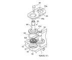
- FIG. 4 and 5 show the detailed structure of the check valve built-in cylinder (nitrogen adsorption container connection cylinder) 60.
- FIG. A pair of stepped through holes 55 are formed in the high end wall 52A in correspondence with the pair of check valve built-in cylinders 60.
- the stepped through hole 55 has a small diameter step 56 and a large diameter step 57.
- the check valve built-in cylinder 60 is airtightly inserted in the small diameter step portion 56 of the stepped through hole 55 via the O ring 61, and the large diameter step portion 57 via the O ring 63. It has a nitrogen adsorption vessel connection pipe 64 inserted airtightly.
- the check valve unit 62 includes a flat circular valve seat 62a and a valve body 62b.
- the valve seat 62a is formed with a valve body holding hole 62c at its center and a plurality of through holes 62d at its periphery. It is formed.
- the valve body 62b has a shaft portion 62f inserted and held in the valve body holding hole 62c and a valve portion 62g which normally closes the through hole 62d.
- the valve body 62b closes the through hole 62d when the pressure in the oxygen tank main body 51 is deformed by the pressure from the outside of the oxygen tank main body 51 and opens the through hole 62d in the valve body holding hole 62c. It is attached.
- a large diameter flange 64a to be inserted into the large diameter step portion 57 is formed.
- the pair of check valve built-in cylinders 60 have the same structure, and the pair of check valve built-in cylinders 60 are fixed to the high end wall 52A of the tank half 52 by a single fixing plate 65. That is, in the fixing plate 65, a pair of through holes 65a corresponding to the pair of nitrogen adsorption container connection pipes 64 are bored, and the pair of nitrogen adsorption container connection pipes 64 are inserted into the pair of through holes 65a.
- the fixing plate 65 is fixed to the high end wall 52A by the fixing screw 66.
- the fixing plate 65 presses and fixes the check valve unit 62 to the small diameter step portion 56 of the stepped through hole 55 via the large diameter flange 64 a.
- a screw seat 52C (FIGS. 3 and 4) for screwing and fixing the fixing screw 66 is formed on the inner surface of the high end wall 52A of the tank half 52.
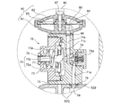
- FIG. 6 and 7 show the detailed structure of the pressure reducing valve 70.
- FIG. A through hole 58 is formed in the low end wall 52B of the tank half 52.
- the pressure reducing valve 70 has a main housing 71 and a sub housing 72, and the main housing 71 is fixed to the low end wall 52B via a fixing screw 73 (FIG. 7).
- a screw seat 52C (FIGS. 3 and 6) for screwing and fixing the fixing screw 73 is formed on the inner surface of the low end wall 52B.
- the main housing 71 has a primary pressure introduction passage 71a and a secondary pressure extraction passage (oxygen outlet) 71b which are in direct communication with the through hole 58 through the O ring 79, and the primary pressure introduction passage 71a and the secondary A main valve 74 is provided in a communication passage that communicates the pressure extraction passage 71b.
- the main valve 74 is a valve that normally shuts off the communication between the primary pressure introduction passage 71a and the secondary pressure extraction passage 71b by means of a valve closing spring 74a.
- the sub housing 72 sandwiches the actuating diaphragm assembly 75 with the main housing 71 to define a secondary pressure chamber 72 a.
- the secondary pressure chamber 72a communicates with the secondary pressure extraction passage 71b via the communication passage 71c.
- the actuating diaphragm assembly 75 has a diaphragm 75a and an actuating piston 75b fixed to the central portion of the diaphragm 75a, and the actuating piston 75b responds to the pressure fluctuation of the secondary pressure chamber 72a (secondary pressure takeout passage 71b).
- the main valve 74 is linked to open and close accordingly.
- the actuating diaphragm assembly 75 moves to the main valve 74 side to move the main valve 74 in the valve opening direction against the force of the valve closing spring 74a.
- the main valve 74 is closed by moving away from the main valve 74.
- the discharge pressure of the secondary pressure discharge passage 71 b can be adjusted by rotating the pressure adjustment screw 76 to adjust the force of the pressure adjustment spring 77 exerted on the actuating diaphragm assembly 75.
- the bacteria filter unit 80 is fixed to the main housing 71 of the pressure reducing valve 70 in communication with the secondary pressure extraction passage 71b.
- the bacteria filter unit 80 sandwiches and supports the bacteria filter 83 between the lower housing 81 and the upper housing 82, and the lower housing 81 is formed with a gas inlet 84 communicating with the secondary pressure discharge passage 71b.
- a gas outlet (oxygen outlet) 85 for taking out the gas (oxygen) which has passed through the bacteria filter 83 is fixed to the upper housing 82.
- the lower housing 81 is fixed via the fixing screw 86 with the O-ring 88 interposed between the inlet of the gas inlet 84 and the outlet of the secondary pressure takeout passage 71b to maintain air tightness.
- the upper housing 82 holding the bacteria filter 83 is fixed with a fixing screw 87 on the lower housing 81 fixed to the main housing 71 of the pressure reducing valve 70.
- the main housing 71 is formed with a screw seat 71 d (FIG. 7) in which the fixing screw 86 is screwed.
- the bacteria filter 83 is a well-known filter that removes impurities such as bacteria contained in oxygen passing therethrough, and is replaced when used for a certain period of time.
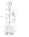
- FIG. 8 is a circuit diagram of the oxygen concentrator oxygen tank unit 50 in which the check valve built-in cylinder 60 and the pressure reducing valve 70 (and the bacteria filter unit 80) are fixed to the high end wall 52A and the low end wall 52B.
- a pair of nitrogen adsorption vessel connecting pipes 64 are connected to the nitrogen adsorption vessels 17 and 18 described in FIG. 10 by appropriate pipeline means, and oxygen from the gas outlet 85 is via a flexible supply tube and a suction device. It is given to the mouth (nose) of the user (patient).
- an oxygen concentration sensor 90 is provided downstream of the outlet of the pressure reducing valve 70, and an oxygen pressure sensor 91 is provided in the oxygen tank main body 51. The outputs from these sensors are input to the control circuit.
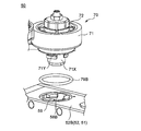
- FIG. 9 shows another embodiment of the oxygen tank unit 50 of the present invention.
- This embodiment is an embodiment in which the pressure reducing valve 70 mounted on the low end wall 52B of the tank half 52 is a bayonet type.
- a plurality of bayonet claws 59 are formed protruding on the inner peripheral portion of the large diameter through hole 58B formed in the low end wall 52B, and the main housing 71 of the pressure reducing valve 70 is a cylinder fitted in the through hole 58B.
- a bayonet claw 71Y engaging with and disengaging from the rod-like portion 71X and the bayonet claw 59 is formed.
- the bayonet claw 59 and the bayonet claw 71Y engage and disengage when they are relatively rotated in a state where the cylindrical portion 71X is inserted into the through hole 58B, as is well known for an interchangeable lens of a single-lens reflex camera.
- a primary pressure introducing passage communicating with the through hole 58B corresponding to the primary pressure introducing passage 71a of FIG. 6 is opened, and the primary pressure introducing passage and the through hole 58B are large. It is airtightly connected via the diameter O-ring 79B.
- the basic configuration in the pressure reducing valve 70 is the same as the configuration of the pressure reducing valve 70 in FIG.
- both the pair of check valve built-in cylinder (nitrogen adsorption vessel connecting cylinder) 60 and the pressure reducing valve 70 are directly attached to the oxygen tank body 51, but even if only one of them is attached directly An effect of simplification of a certain configuration can be obtained.
- the bacteria filter unit 80 is fixed to the main housing 71 of the pressure reducing valve 70, but the bacteria filter unit 80 is omitted (the secondary pressure discharge passage 71b of the pressure reducing valve 70 is directly connected to the air outlet). Aspect is also possible.
- the oxygen tank unit for an oxygen concentrator of the present invention can be widely used for medical use.
Landscapes
- Health & Medical Sciences (AREA)
- Engineering & Computer Science (AREA)
- Chemical & Material Sciences (AREA)
- General Health & Medical Sciences (AREA)
- Hematology (AREA)
- Veterinary Medicine (AREA)
- Public Health (AREA)
- Emergency Medicine (AREA)
- Pulmonology (AREA)
- Anesthesiology (AREA)
- Biomedical Technology (AREA)
- Heart & Thoracic Surgery (AREA)
- Animal Behavior & Ethology (AREA)
- Life Sciences & Earth Sciences (AREA)
- Oil, Petroleum & Natural Gas (AREA)
- Analytical Chemistry (AREA)
- General Chemical & Material Sciences (AREA)
- Chemical Kinetics & Catalysis (AREA)
- Separation Of Gases By Adsorption (AREA)
- Oxygen, Ozone, And Oxides In General (AREA)
Priority Applications (3)
| Application Number | Priority Date | Filing Date | Title |
|---|---|---|---|
| KR1020137021357A KR20140005230A (ko) | 2011-03-25 | 2012-02-16 | 산소농축장치용 산소탱크유닛 |
| US14/006,989 US20140013954A1 (en) | 2011-03-25 | 2012-02-16 | Oxygen tank unit for oxygen enricher |
| CN2012800149157A CN103458952A (zh) | 2011-03-25 | 2012-02-16 | 氧气浓缩装置用氧气瓶单元 |
Applications Claiming Priority (2)
| Application Number | Priority Date | Filing Date | Title |
|---|---|---|---|
| JP2011067250A JP2012200387A (ja) | 2011-03-25 | 2011-03-25 | 酸素濃縮装置用酸素タンクユニット |
| JP2011-067250 | 2011-03-25 |
Publications (1)
| Publication Number | Publication Date |
|---|---|
| WO2012132604A1 true WO2012132604A1 (ja) | 2012-10-04 |
Family
ID=46930366
Family Applications (1)
| Application Number | Title | Priority Date | Filing Date |
|---|---|---|---|
| PCT/JP2012/053620 Ceased WO2012132604A1 (ja) | 2011-03-25 | 2012-02-16 | 酸素濃縮装置用酸素タンクユニット |
Country Status (6)
| Country | Link |
|---|---|
| US (1) | US20140013954A1 (enExample) |
| JP (1) | JP2012200387A (enExample) |
| KR (1) | KR20140005230A (enExample) |
| CN (1) | CN103458952A (enExample) |
| TW (1) | TW201238616A (enExample) |
| WO (1) | WO2012132604A1 (enExample) |
Families Citing this family (8)
| Publication number | Priority date | Publication date | Assignee | Title |
|---|---|---|---|---|
| JP6252941B2 (ja) * | 2014-01-24 | 2017-12-27 | Smc株式会社 | 酸素濃縮器 |
| JP6260776B2 (ja) * | 2014-02-14 | 2018-01-17 | Smc株式会社 | 酸素濃縮器 |
| US10360619B2 (en) * | 2014-03-28 | 2019-07-23 | Paypal, Inc. | Item location assistant |
| US10706380B2 (en) | 2014-05-08 | 2020-07-07 | Visa International Service Association | Split shipment processing |
| DE102014217021A1 (de) * | 2014-08-27 | 2016-03-03 | Skf Lubrication Systems Germany Ag | Gehäuse für eine Vorrichtung zum dosierten Verteilen eines Mediums sowie eine Dosiereinrichtung zur Verwendung in dem Gehäuse |
| GB201507047D0 (en) | 2015-04-24 | 2015-06-10 | Visa Europe Ltd | Method of retaining transaction context |
| WO2017141263A1 (en) * | 2016-02-18 | 2017-08-24 | O2-Matic Products Private Limited | Modular portable oxygen generator |
| CN112327956B (zh) * | 2020-11-16 | 2023-03-14 | 山东尚健医疗科技有限公司 | 一种制氧机智能调压装置 |
Citations (3)
| Publication number | Priority date | Publication date | Assignee | Title |
|---|---|---|---|---|
| JP2006166998A (ja) * | 2004-12-13 | 2006-06-29 | Fukuda Denshi Co Ltd | 吸着式ガス生成装置 |
| JP2008264064A (ja) * | 2007-04-17 | 2008-11-06 | Ngk Spark Plug Co Ltd | 酸素濃縮装置 |
| JP2009125306A (ja) * | 2007-11-22 | 2009-06-11 | Terumo Corp | 酸素濃縮装置 |
Family Cites Families (21)
| Publication number | Priority date | Publication date | Assignee | Title |
|---|---|---|---|---|
| FR959113A (enExample) * | 1944-05-10 | 1950-03-24 | ||
| US4149556A (en) * | 1978-09-26 | 1979-04-17 | Respiratory Care, Inc. | Tubular connector having audible relief valve |
| US4449990A (en) * | 1982-09-10 | 1984-05-22 | Invacare Respiratory Corp. | Method and apparatus for fractioning oxygen |
| JPS61280870A (ja) * | 1985-06-07 | 1986-12-11 | 井上 理文 | 酸素吸入装置の酸素富化器 |
| US5593478A (en) * | 1994-09-28 | 1997-01-14 | Sequal Technologies, Inc. | Fluid fractionator |
| US5531807A (en) * | 1994-11-30 | 1996-07-02 | Airsep Corporation | Apparatus and method for supplying oxygen to passengers on board aircraft |
| US5988165A (en) * | 1997-10-01 | 1999-11-23 | Invacare Corporation | Apparatus and method for forming oxygen-enriched gas and compression thereof for high-pressure mobile storage utilization |
| DE10100173A1 (de) * | 2001-01-04 | 2002-07-11 | Fev Motorentech Gmbh | Vollvariabler mechanischer Ventiltrieb für eine Kolbenbrennkraftmaschine |
| ES2328911T3 (es) * | 2001-10-30 | 2009-11-19 | Teijin Limited | Dispositivo de enriquecimiento en oxigeno. |
| CN2540188Y (zh) * | 2002-04-17 | 2003-03-19 | 中国科学院沈阳自动化研究所 | 具有氧浓度检测功能的医用小型制氧机 |
| US6740146B2 (en) * | 2002-09-12 | 2004-05-25 | Edward L. Simonds | Oxygen concentrator |
| US7402193B2 (en) * | 2005-04-05 | 2008-07-22 | Respironics Oxytec, Inc. | Portable oxygen concentrator |
| US7329304B2 (en) * | 2005-04-05 | 2008-02-12 | Respironics Oxytec, Inc. | Portable oxygen concentrator |
| US7510601B2 (en) * | 2005-12-20 | 2009-03-31 | Air Products And Chemicals, Inc. | Portable medical oxygen concentrator |
| US8753435B2 (en) * | 2006-04-03 | 2014-06-17 | Ric Investments, Llc | Portable oxygen concentrator |
| JP3139801U (ja) * | 2006-12-31 | 2008-02-28 | 冬雷 王 | 携帯型psa式酸素発生器 |
| JP4799454B2 (ja) * | 2007-03-20 | 2011-10-26 | 帝人ファーマ株式会社 | 圧力スイング吸着型酸素濃縮器 |
| JP2009119012A (ja) * | 2007-11-14 | 2009-06-04 | Advanex Inc | カフ付医療具用インジケータ |
| JP5226282B2 (ja) * | 2007-11-15 | 2013-07-03 | 日本特殊陶業株式会社 | 酸素濃縮装置 |
| EP2500055B1 (en) * | 2007-11-15 | 2013-12-25 | Teijin Pharma Limited | Oxygen concentrator |
| JP5202117B2 (ja) * | 2008-06-10 | 2013-06-05 | 藤倉ゴム工業株式会社 | 減圧弁 |
-
2011
- 2011-03-25 JP JP2011067250A patent/JP2012200387A/ja active Pending
-
2012
- 2012-02-06 TW TW101103736A patent/TW201238616A/zh unknown
- 2012-02-16 KR KR1020137021357A patent/KR20140005230A/ko not_active Withdrawn
- 2012-02-16 US US14/006,989 patent/US20140013954A1/en not_active Abandoned
- 2012-02-16 CN CN2012800149157A patent/CN103458952A/zh active Pending
- 2012-02-16 WO PCT/JP2012/053620 patent/WO2012132604A1/ja not_active Ceased
Patent Citations (3)
| Publication number | Priority date | Publication date | Assignee | Title |
|---|---|---|---|---|
| JP2006166998A (ja) * | 2004-12-13 | 2006-06-29 | Fukuda Denshi Co Ltd | 吸着式ガス生成装置 |
| JP2008264064A (ja) * | 2007-04-17 | 2008-11-06 | Ngk Spark Plug Co Ltd | 酸素濃縮装置 |
| JP2009125306A (ja) * | 2007-11-22 | 2009-06-11 | Terumo Corp | 酸素濃縮装置 |
Also Published As
| Publication number | Publication date |
|---|---|
| JP2012200387A (ja) | 2012-10-22 |
| TW201238616A (en) | 2012-10-01 |
| CN103458952A (zh) | 2013-12-18 |
| US20140013954A1 (en) | 2014-01-16 |
| KR20140005230A (ko) | 2014-01-14 |
Similar Documents
| Publication | Publication Date | Title |
|---|---|---|
| WO2012132604A1 (ja) | 酸素濃縮装置用酸素タンクユニット | |
| KR100416424B1 (ko) | 유체 저장 및 분배 시스템 | |
| KR100692995B1 (ko) | 유체의 저장 및 분배를 위한 장치 및 방법과 사용 유체의공급 방법 | |
| TW490541B (en) | Gas storage and dispensing system comprising regulator interiorly disposed in fluid containment vessel and adjustable in situ therein | |
| CN103813824B (zh) | 氧气浓缩器供应管路超压保护 | |
| JP2011231935A5 (enExample) | ||
| US9321001B2 (en) | Portable oxygen concentrator with integrated manifold | |
| CN102576230A (zh) | 流控制器 | |
| JP2012200387A5 (enExample) | ||
| JP2009538223A (ja) | 流体貯蔵及び分給システム | |
| US5497803A (en) | Pressure regulator for the first stage of two-stage aqualungs | |
| TW200602116A (en) | Built in purifier for reactive gases | |
| CN104843643A (zh) | 氧浓缩器 | |
| JP6006520B2 (ja) | 酸素濃縮装置およびそれに用いるパイロット弁ユニット | |
| EP1715225B1 (en) | Dual-flow valve and internal processing vessel isolation system | |
| CN107166164A (zh) | 设有泄气装置的集成瓶阀 | |
| JP4921231B2 (ja) | 酸素濃縮装置 | |
| JP2009543721A5 (enExample) | ||
| US10024447B2 (en) | Modular manifold assembly for sequentially drawing fluid from fluid storage tanks | |
| RU2059419C1 (ru) | Устройство для газовой дезинфекции | |
| KR101510573B1 (ko) | 콤팩트 흡착식 건조기 | |
| RU2012152885A (ru) | Устройство для ингаляции | |
| CN211799818U (zh) | 一种用于等离子射流设备的选择性气体吸附罐 | |
| JP2006166998A (ja) | 吸着式ガス生成装置 | |
| CA1099218A (en) | Pneumatically actuated electronic control for a fluid mixture adsorption separator |
Legal Events
| Date | Code | Title | Description |
|---|---|---|---|
| 121 | Ep: the epo has been informed by wipo that ep was designated in this application |
Ref document number: 12765082 Country of ref document: EP Kind code of ref document: A1 |
|
| ENP | Entry into the national phase |
Ref document number: 20137021357 Country of ref document: KR Kind code of ref document: A |
|
| WWE | Wipo information: entry into national phase |
Ref document number: 14006989 Country of ref document: US |
|
| NENP | Non-entry into the national phase |
Ref country code: DE |
|
| 122 | Ep: pct application non-entry in european phase |
Ref document number: 12765082 Country of ref document: EP Kind code of ref document: A1 |