WO2012132599A1 - 並列電源システム - Google Patents
並列電源システム Download PDFInfo
- Publication number
- WO2012132599A1 WO2012132599A1 PCT/JP2012/053582 JP2012053582W WO2012132599A1 WO 2012132599 A1 WO2012132599 A1 WO 2012132599A1 JP 2012053582 W JP2012053582 W JP 2012053582W WO 2012132599 A1 WO2012132599 A1 WO 2012132599A1
- Authority
- WO
- WIPO (PCT)
- Prior art keywords
- arm
- inductor
- power supply
- power source
- supply system
- Prior art date
- Legal status (The legal status is an assumption and is not a legal conclusion. Google has not performed a legal analysis and makes no representation as to the accuracy of the status listed.)
- Ceased
Links
Images




Classifications
-
- H—ELECTRICITY
- H01—ELECTRIC ELEMENTS
- H01M—PROCESSES OR MEANS, e.g. BATTERIES, FOR THE DIRECT CONVERSION OF CHEMICAL ENERGY INTO ELECTRICAL ENERGY
- H01M10/00—Secondary cells; Manufacture thereof
- H01M10/42—Methods or arrangements for servicing or maintenance of secondary cells or secondary half-cells
- H01M10/44—Methods for charging or discharging
- H01M10/441—Methods for charging or discharging for several batteries or cells simultaneously or sequentially
-
- H—ELECTRICITY
- H02—GENERATION; CONVERSION OR DISTRIBUTION OF ELECTRIC POWER
- H02J—ELECTRIC POWER NETWORKS; CIRCUIT ARRANGEMENTS OR SYSTEMS FOR SUPPLYING OR DISTRIBUTING ELECTRIC POWER; SYSTEMS FOR STORING ELECTRIC ENERGY
- H02J2207/00—Details of circuit arrangements for charging or discharging batteries or supplying loads from batteries
- H02J2207/20—Charging or discharging characterised by the power electronics converter
-
- H—ELECTRICITY
- H02—GENERATION; CONVERSION OR DISTRIBUTION OF ELECTRIC POWER
- H02M—APPARATUS FOR CONVERSION BETWEEN AC AND AC, BETWEEN AC AND DC, OR BETWEEN DC AND DC, AND FOR USE WITH MAINS OR SIMILAR POWER SUPPLY SYSTEMS; CONVERSION OF DC OR AC INPUT POWER INTO SURGE OUTPUT POWER; CONTROL OR REGULATION THEREOF
- H02M3/00—Conversion of DC power input into DC power output
- H02M3/02—Conversion of DC power input into DC power output without intermediate conversion into AC
- H02M3/04—Conversion of DC power input into DC power output without intermediate conversion into AC by static converters
- H02M3/10—Conversion of DC power input into DC power output without intermediate conversion into AC by static converters using discharge tubes with control electrode or semiconductor devices with control electrode
- H02M3/145—Conversion of DC power input into DC power output without intermediate conversion into AC by static converters using discharge tubes with control electrode or semiconductor devices with control electrode using devices of a triode or transistor type requiring continuous application of a control signal
- H02M3/155—Conversion of DC power input into DC power output without intermediate conversion into AC by static converters using discharge tubes with control electrode or semiconductor devices with control electrode using devices of a triode or transistor type requiring continuous application of a control signal using semiconductor devices only
- H02M3/156—Conversion of DC power input into DC power output without intermediate conversion into AC by static converters using discharge tubes with control electrode or semiconductor devices with control electrode using devices of a triode or transistor type requiring continuous application of a control signal using semiconductor devices only with automatic control of output voltage or current, e.g. switching regulators
- H02M3/158—Conversion of DC power input into DC power output without intermediate conversion into AC by static converters using discharge tubes with control electrode or semiconductor devices with control electrode using devices of a triode or transistor type requiring continuous application of a control signal using semiconductor devices only with automatic control of output voltage or current, e.g. switching regulators including plural semiconductor devices as final control devices for a single load
-
- Y—GENERAL TAGGING OF NEW TECHNOLOGICAL DEVELOPMENTS; GENERAL TAGGING OF CROSS-SECTIONAL TECHNOLOGIES SPANNING OVER SEVERAL SECTIONS OF THE IPC; TECHNICAL SUBJECTS COVERED BY FORMER USPC CROSS-REFERENCE ART COLLECTIONS [XRACs] AND DIGESTS
- Y02—TECHNOLOGIES OR APPLICATIONS FOR MITIGATION OR ADAPTATION AGAINST CLIMATE CHANGE
- Y02E—REDUCTION OF GREENHOUSE GAS [GHG] EMISSIONS, RELATED TO ENERGY GENERATION, TRANSMISSION OR DISTRIBUTION
- Y02E60/00—Enabling technologies; Technologies with a potential or indirect contribution to GHG emissions mitigation
- Y02E60/10—Energy storage using batteries
Definitions
- the present invention relates to a parallel power supply system in which a plurality of power supplies are connected in parallel, and more particularly to a parallel power supply system that supplies power to a load through which a variable current flows.
- Patent Document 1 discloses an assembled battery in which batteries are connected in parallel as a power source for an electric vehicle, a hybrid vehicle, or the like.
- the voltage drop due to the internal resistance of each battery, the wiring resistance of the series battery group, and the like is different for each series battery group, resulting in variations in the current flowing through each series battery group. End up. Therefore, the degree of battery decrease for each series battery group is different, and the variation in the electromotive force of the battery for each series battery group increases with time. If there is variation in the electromotive force of the battery, a return current from the series battery group having a large electromotive force to the series battery group having a small electromotive force may occur. When a return current is generated, an unintended charging / discharging cycle proceeds, so that the battery life is shortened. In addition, power loss becomes a problem due to unintended charging and discharging.
- a load current to be borne by each battery is calculated from a measured value of the current flowing through the load, and this is compared with a measured current value flowing through each battery. It is necessary to perform complicated control such as adjusting the output voltage of the DC-DC converter based on this. In addition, since it is necessary to install a current measuring instrument, a DC-DC converter, etc., the equipment cost is increased. Similarly, when current control is performed using an inverter or a chopper, there is a need for complicated control and equipment costs. In particular, in the case of a large parallel power supply system (such as a large power storage device) through which a large current flows, the equipment becomes expensive, and it is difficult to introduce this into a large parallel power supply system.
- a large parallel power supply system such as a large power storage device
- the present invention has been made in view of the above circumstances, and an object of the present invention is to provide a parallel power supply system capable of smoothing the current flowing through each power supply without performing control with an inexpensive and simple apparatus configuration.
- a parallel power supply system is a parallel power supply system that supplies power to a load through which a fluctuating current flows, the first arm having a first power supply and a first inductor connected in series to the first power supply, A second arm connected in parallel with the first arm and having a second power source and a second inductor connected in series to the second power source, the first inductor and the second inductor being the first arm
- the second inductor is connected so that an electromotive force in a direction to increase the output voltage of the second arm is generated in the second inductor.
- the parallel power supply system includes an inductor provided between a connection point of the first arm and the second arm and the load, and one end connected between the inductor and the load.
- a third arm having a third inductor connected in series to three power sources, and the inductor and the third inductor have a current flowing from the first arm and the second arm toward the load, It may be wired so that an electromotive force in a direction to increase the output voltage of the third arm is generated in the third inductor.
- the parallel power supply system further includes a third arm connected in parallel to the first arm and the second arm, and having a third power supply and a pair of third inductors connected in series to the third power supply,
- One arm includes a pair of the first inductors connected in series to the first power source
- the second arm includes a pair of the second inductors connected in series to the second power source
- One of the one inductor and the one of the second inductor has an electromotive force in a direction of increasing the output voltage of the second arm when a current flows from the first arm toward the load.
- One of the first inductors and one of the third inductors when the current flows from the first arm toward the load.
- An electromotive force in the direction of increasing the voltage is connected so as to act on one of the third inductors, and the other of the second inductors and the other of the third inductors are directed from the second arm toward the load.
- the electromotive force in the direction of increasing the output voltage of the third arm may be connected so as to act on the other of the third inductor.
- the first power supply and the second power supply may be batteries, and may be primary batteries or secondary batteries.
- the parallel power supply system can smooth the current between the arms by mutual induction of the inductors provided in each arm and prevent the generation of the ring current
- the first power supply and the second power supply are primary.
- unintended primary battery charging due to ring current can be suppressed.
- the first power source and the second power source are secondary batteries
- the life of the secondary battery is extended by preventing the generation of ring current, for example, the maintenance of the secondary battery cannot be performed over a long period of time.
- a highly reliable parallel power supply system that can be operated even under circumstances can be obtained.
- first power source and the second power source are secondary batteries
- an external power source is connected to the first arm and the second arm instead of the load, and the first power source and the power source are supplied from the external power source.
- the second power supply may be charged.
- a turn ratio between the first inductor and the second inductor may be set so that a current ratio between the first arm and the second arm becomes a predetermined value.
- the turn ratio between the first inductor and the second inductor may be set according to the maximum output current ratio or the maximum output power ratio between the first power source and the second power source.
- the first power source and the second power source are batteries
- the first inductor and the second inductor according to a capacity ratio (battery capacity ratio) between the first power source and the second power source.
- the turn ratio may be set.
- the load through which the variable current flows may be, for example, an inverter, a chopper, or a switching power supply.
- the first inductor and the second inductor are connected so that an electromotive force in the direction of increasing the output voltage of the second arm is generated in the second inductor. Therefore, when current fluctuation occurs in the first arm and the second arm, the current between the arms is smoothed by the mutual induction of the first inductor and the second inductor. Therefore, the current flowing through each power source can be smoothed without any control by an inexpensive and simple device configuration in which an inductor is provided in each arm.
- FIG. 1 is a diagram illustrating a configuration example of a parallel power supply system according to the first embodiment.
- the parallel power supply system 10 is connected to a load 4 having a switching element 2 and supplies power to the load 4.
- the load 4 is a load having the switching element 2 (for example, an inverter, a chopper, a switching power supply, etc.), and can cause a current fluctuation in a short time by the operation of the switching element 2.
- the load 4 may not have the switching element 2 as long as a variable current flows.
- the parallel power supply system 10 has a configuration in which a first arm 12 and a second arm 22 are connected in parallel.
- the first arm 12 includes a first power source 14 and a first inductor 16 connected in series to the first power source 14.
- the second arm 22 includes a second power source 24 and a second inductor 26 connected in series to the second power source 24.
- reference numerals 18 and 28 denote resistance components such as wiring resistance of each arm (12, 22) and battery internal resistance.
- the first inductor 16 and the second inductor 26 have an electromotive force in the direction of increasing the output voltage of the second arm 22 when a current flows from the first arm 12 toward the load 4.
- FIG. 1 shows an example in which the winding start terminals (black circles in FIG. 1) of the first inductor 16 and the second inductor 26 are staggered, but in this example, the first inductor 16 has its winding start terminals.
- the current flows from the opposite side to the second inductor 26, and the current flows from the winding start terminal side to the second inductor 26.
- the winding start terminal May not be alternate.
- the point is that when the current flows from the first arm 12 toward the load 4, the first inductor 16 and the second inductor 16 are connected so that the electromotive force in the direction of increasing the output voltage of the second arm 22 acts on the second inductor 26.
- the inductor 26 is connected.
- the first inductor 16 and the second inductor 26 are wound around the common core 20, and the number of turns of both is the same.
- the first inductor 16 and the second inductor 26 By connecting the first inductor 16 and the second inductor 26 in this manner, when current fluctuation occurs in the first arm 12 and the second arm 22 due to the operation of the switching element 2, the first inductor 16 and the second inductor 26
- the current between the arms is smoothed by mutual induction. For example, when current starts to flow through the first arm 12 and the second arm 22 due to the operation of the switching element 2, the resistance component 18 of the first arm 12 is smaller than the resistance component 28 of the second arm 22, and thus the first arm Consider the case where more current is going to flow through 12.
- the power source (14, 24) is not particularly limited as long as it is incorporated in the parallel power supply system 10 and can supply power to the load 4. Any power source such as a battery, a large-capacity capacitor (electric double layer capacitor), or a generator can be used. Can be used.
- a primary battery or a secondary battery can be used as the power source (14, 24).
- the parallel power supply system 10 can smooth the current between the arms by the mutual induction of the inductors (16, 26) provided in the arms (12, 22), thereby preventing the generation of the ring current.
- the power source (14, 24) is a primary battery, unintended charging of the primary battery due to the ring current can be suppressed.
- the power source (14, 24) is a secondary battery, the life of the secondary battery can be extended by preventing the generation of ring current. Therefore, for example, the highly reliable parallel power supply system 10 that can be operated even in a situation where the maintenance of the secondary battery cannot be performed over a long period of time can be achieved.
- the power source (14, 24) is a secondary battery
- an external power source is connected to the first arm 12 and the second arm 22 instead of the load 4, and the power source (14, 24) is supplied by the power supplied from the external power source. 24) may be charged.
- the currents flowing through the arms (12, 2) are equalized by mutual induction of the inductors (16, 26). For example, when the current starts to flow from the external power source to the first arm 12 and the second arm 22, the resistance component 18 of the first arm 12 is smaller than the resistance component 28 of the second arm 22, so Let us consider a case in which a current flows through.
- the first inductor 16 and the second inductor 26 have the first ratio so that the ratio of the current flowing through the arms (12, 22) is a predetermined value.
- the turn ratio between the inductor 16 and the second inductor 26 may be arbitrarily set.
- the turn ratio of the first inductor 16 and the second inductor 26 may be adjusted according to the maximum output current ratio or the maximum output power ratio of each power source (14, 24).
- each power source (14, 24) is a battery
- the turns ratio of the first inductor 16 and the second inductor 26 may be adjusted according to the capacity ratio of each power source. This makes it possible to apply to power sources (14, 24) having different characteristics (maximum output current ratio, maximum output power ratio, battery capacity ratio, etc.).
- FIG. 2 is a diagram illustrating a configuration example of the parallel power supply system according to the second embodiment.
- the parallel power supply system 30 shown in the figure is the same as the parallel power supply system 10 of the first embodiment except that current smoothing is performed for three arms. Therefore, the same code
- the inductor is connected between the connection point P 1 of the first arm 12 and the second arm 22 and the load 4.
- 37 is provided.
- One end of the third arm 32 is connected between the inductor 37 and the load 4.
- the third arm 32 includes a third power source 34 and a third inductor 36 connected in series to the third power source 34.
- the resistance component 38 is a wiring resistance of the third arm 32, a battery internal resistance, or the like.
- the inductor 37 and the third inductor 36 have an electromotive force in the direction of increasing the output voltage of the third arm 32 when a current flows from the first arm 12 and the second arm 22 toward the load 4.
- the inductor 37 is wound around the core 20 common to the third inductor 36, and the number of turns is about half of the number of turns of the third inductor 36. The reason why the number of turns of the inductor 37 is about half that of the third inductor 36 is that the current flowing through the inductor 37 is about twice the current flowing through the third inductor 36.
- the current between the first arm 12 and the second arm 22 is smoothed by the mutual induction of the first inductor 16 and the second inductor 26. Further, the mutual induction of the inductor 37 and the third inductor 36 smoothes the current after passing through the first arm 12 and the second arm 22 (current flowing through the inductor 37) and the current flowing through the third arm 32. . As a result, variations in current between the arms (12, 22, 32) are suppressed.
- the ratio of the current flowing through each arm (12, 22, 32) is set to a predetermined value.
- the turn ratio between the inductor 37 and the third inductor 36 may be arbitrarily set.
- the turn ratio between the number of turns of the inductor 37 and the third inductor 36 may be adjusted according to the maximum output current ratio or the maximum output power ratio of each power source (14, 24, 34).
- each power supply (14, 24, 34) is a battery, you may adjust the turns ratio of the number of turns of the inductor 37 and the 3rd inductor 36 according to the capacity ratio of each power supply.
- FIG. 3 is a diagram illustrating a configuration example of a parallel power supply system according to the third embodiment.
- the parallel power supply system 40 shown in the figure is the same as the parallel power supply system 30 of the second embodiment except that the way of connecting the three arms is different. Therefore, the same code
- the three arms (12, 22, 32) are connected in parallel, and a power source (14, 24, 34) and a pair of inductors (16A, 16B, 16) connected in series to the power source, respectively. 26A, 26B, 36A, 36B).
- the pair of inductors of each arm (12, 22, 32) is provided so as to be able to mutually induct with the inductors of the other arms. Note that the number of turns of the inductors that form a pair so as to cause mutual induction is equal.
- the first inductor 16A and the second inductor 26A are such that when a current flows from the first arm 12 toward the load 4, the electromotive force in the direction of increasing the output voltage of the second arm 22 is the second inductor. It is wound around a common core 20 so as to occur at 26A.
- the first inductor 16B and the third inductor 36B generate an electromotive force in the third inductor 36B in a direction to increase the output voltage of the third arm 32 when a current flows from the first arm 12 toward the load 4. It is wound around a common core 20 as shown. Furthermore, the second inductor 26B and the third inductor 36A generate an electromotive force in the third inductor 36A in a direction to increase the output voltage of the third arm 32 when a current flows from the second arm 22 toward the load 4. It is wound around a common core 20 as shown.
- the current between the first arm 12 and the second arm 22 is smoothed by the mutual induction of the first inductor 16A and the second inductor 26A. Further, the current between the first arm 12 and the third arm 32 is smoothed by the mutual induction of the first inductor 16B and the third inductor 36B. The current between the second arm 22 and the third arm 32 is smoothed by mutual induction of the second inductor 26B and the third inductor 36A. As a result, variations in current between the arms (12, 22, 32) are suppressed. Moreover, since the number of inductors of each arm (12, 22, 32) is equal, the impedance of each arm can be made uniform.
- the ratio of the currents flowing through the arms (12, 22, 32) is a predetermined value.
- the turns ratio of the inductors constituting each pair may be arbitrarily set.
- the turns ratio of the inductors constituting each pair may be adjusted according to the maximum output current ratio or the maximum output power ratio of each power source (14, 24, 34).
- each power supply (14, 24, 34) is a battery, you may adjust the turns ratio of the inductor which comprises each pair according to the capacity ratio of each power supply.
- the inductor may be provided on the negative terminal side of the power source, or the inductor may be provided on both the positive terminal side and the negative terminal side of the power source. Needless to say, it may be provided.
- the number of arms is two to three has been described, but the number of arms may be four or more.
- a parallel power supply system having an arbitrary number of arms may be realized by appropriately combining the modes. For example, in the case of a parallel power supply system using four arms, a plurality of connection modes of the two arms of the first embodiment may be combined.
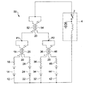
- FIG. 4 is a diagram showing a configuration example of a parallel power supply system using four arms.
- the parallel power supply system 50 shown in the figure is applied to four arms by combining the connection modes of the first embodiment.
- the fourth arm 42 includes a fourth inductor 46 connected in series to the fourth power supply 44 as in the other arms.
- the reference numeral 48 indicates a resistance component of the fourth arm 42.
- the two arm pairs of the first arm 12, the second arm 22, the third arm 32, and the fourth arm 42 are connected in the same connection manner as in the first embodiment.
- the first inductor 16 of the first arm 12 and the second inductor 26 of the second arm 22 have the output voltage of the second arm 22 when a current flows from the first arm 12 toward the load 4. Is wound around the common core 20 so as to generate an electromotive force in the direction of increasing the second inductor 26.
- the third inductor 36 of the third arm 32 and the fourth inductor 46 of the fourth arm 42 increase the output voltage of the fourth arm 42 when current flows from the third arm 32 toward the load 4.
- an inductor 52 is provided between the connection point P1 of the first arm 12 and the second arm 22 and the load 4, and between the connection point P2 of the third arm 32 and the fourth arm 42 and the load 4.
- An inductor 54 is provided. When the current flows from the first arm 12 and the second arm 22 toward the load 4, the inductor 52 and the inductor 54 generate an electromotive force in a direction that increases the output voltage of the third arm 32 and the fourth arm 42. It is wound around the common core 20 so as to be generated in the inductor 54.
- the arm (by the mutual induction of the first inductor 16 and the second inductor 26, the mutual induction of the third inductor 36 and the fourth inductor 46, and the mutual induction of the inductor 52 and the inductor 54). 12, 22, 32, 42), the variation in current is suppressed.
- a pair of inductors (16, 16A, 16B, 26, 26A, 26B, 36, 36A, 36B, 37, 46, 52, 54) is wound around the common core 20
- the structure of the core is not particularly limited as long as the paired inductors are connected so as to cause the above-described mutual induction.
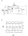
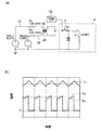
- FIG. 5 is a diagram related to the calculation performed to confirm the current smoothing action of the inductor when there is a difference in the internal resistance of the battery
- FIG. (B) is a graph which shows the calculation result of the time-dependent change of an electric current.
- 6A and 6B are diagrams relating to the calculation performed without using the inductor for comparison.
- FIG. 6A is a circuit configuration diagram targeted for the calculation
- FIG. 6B is a calculation result of the change over time of the current. It is a graph to show.
- the resistances R2 and R3 of the arms (12, 22) are 1.6 m ⁇ and 2.0 m ⁇ , respectively.
- Each arm is provided with inductors (16, 26) wound around a common core. In this circuit configuration, the current flowing through each resistor was calculated.
- the switching element 2 of the load 4 is repeatedly opened and closed based on the pulse signal output from the PWM control unit 52.
- IL1 means the magnitude of current flowing through LOAD1.
- FIG. 6A the circuit configuration shown in FIG. 6A is the same as the circuit configuration shown in FIG. 5A except that an inductor is not provided in each arm.
- Figure 6 was calculated the current through each resistor in the circuit configuration shown in (a), as shown in FIG. 6 (b), a current flows through the current I R5 [A] and a resistor R6 through resistor R5 I R6 [A ] Was larger than that in FIG.
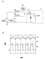
- FIG. 7 is a diagram related to the calculation performed to confirm the current smoothing action of the inductor when balanced (when in equilibrium) when discharging from each battery when there is a difference in the internal resistance of the battery.
- FIG. 7A is a circuit configuration diagram targeted for calculation
- FIG. 7B is a graph showing a calculation result of a change in current over time.
- FIG. 8 is a diagram related to a calculation performed without using an inductor for comparison
- FIG. 8A is a circuit configuration diagram for calculation
- FIG. 8B is a calculation result of current change over time. It is a graph to show.
- the circuit configuration shown in FIG. 8A is the same as the circuit configuration shown in FIG. 7A except that an inductor is not provided in each arm. 8 was calculated the current through each resistor in the circuit configuration shown in (a), as shown in FIG. 8 (b), a current flows through the current I R5 [A] and a resistor R6 through resistor R5 I R6 [A ] Was larger than that in FIG. Also, I R5 flowing through the resistor R5, when the switch S2 is OFF, has a negative current, it was found that the resistance R5 and ring current. Such a ring current was not confirmed in FIG.
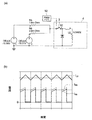
- FIG. 9 is a diagram relating to calculations performed to confirm the current smoothing action of the inductor when balanced (when balanced) when charging each battery when there is a difference in the internal resistance of the battery.
- FIG. 9A is a circuit configuration diagram targeted for calculation
- FIG. 9B is a graph showing a calculation result of a change in current with time.
- FIG. 10 is a diagram related to a calculation performed without using an inductor for comparison.
- FIG. 10A is a circuit configuration diagram for calculation
- FIG. 10B is a calculation result of current change over time. It is a graph to show.
- FIG. 10A is the same as the circuit configuration shown in FIG. 9A except that no inductor is provided in each arm.
- Figure 10 was calculated the current through each resistor in the circuit configuration shown in (a), FIG. 10 (b), the electric currents flowing through R5 I R5 [A] and the current flowing through the resistor R6 I R6 [A ] was larger than that in FIG. Also, I R5 flowing through the resistor R5, the switch S2 is at OFF, the has a negative current, it was found that a large ring current flows than 9 to resistor R5 (b).
Landscapes
- Engineering & Computer Science (AREA)
- Manufacturing & Machinery (AREA)
- Chemical & Material Sciences (AREA)
- Chemical Kinetics & Catalysis (AREA)
- Electrochemistry (AREA)
- General Chemical & Material Sciences (AREA)
- Charge And Discharge Circuits For Batteries Or The Like (AREA)
- Dc-Dc Converters (AREA)
- Secondary Cells (AREA)
Abstract
並列電源システム(10,30,40,50)は、負荷4に電力を供給する電力供給源である。並列電源システム(10,30,40,50)では、第1電源14及びこの第1電源14に直列接続された第1インダクタ16を有する第1アーム12と、第2電源24及びこの第2電源24に直列接続された第2インダクタ26を有する第2アーム22とが並列に接続されている。第1インダクタ16と第2インダクタ26とは、第1アーム12から負荷4に向かって電流が流れたとき、第2アーム22の出力電圧を高める方向の起電力が第2インダクタ26に発生するように結線されている。
Description
本発明は、複数の電源を並列に接続した並列電源システムに係り、特に、変動電流が流れる負荷に電力を供給する並列電源システムに関する。
従来から、電源を大容量化するために電源を複数並列に接続した並列電源システムが知られている。
例えば、特許文献1には、電気自動車やハイブリッド自動車等の電源として、電池を並列に接続した組電池が開示されている。
ところが、特許文献1のような組電池では、各電池の内部抵抗や直列電池群の配線抵抗等に起因する電圧降下が直列電池群ごとに異なるため、各直列電池群を流れる電流のばらつきが生じてしまう。そのため、直列電池群ごとの電池の減り具合が異なり、直列電池群ごとの電池の起電力のばらつきが経時的に大きくなってしまう。電池の起電力のばらつきがあると、起電力の大きな直列電池群から起電力の小さな直列電池群に向かう還電流が生じてしまうことがある。そして、還電流が発生すると、意図しない充放電のサイクルが進むことになるので、電池の寿命が縮まる。また、意図しない充放電によって、電力のロスが問題となる。
ところが、特許文献1のような組電池では、各電池の内部抵抗や直列電池群の配線抵抗等に起因する電圧降下が直列電池群ごとに異なるため、各直列電池群を流れる電流のばらつきが生じてしまう。そのため、直列電池群ごとの電池の減り具合が異なり、直列電池群ごとの電池の起電力のばらつきが経時的に大きくなってしまう。電池の起電力のばらつきがあると、起電力の大きな直列電池群から起電力の小さな直列電池群に向かう還電流が生じてしまうことがある。そして、還電流が発生すると、意図しない充放電のサイクルが進むことになるので、電池の寿命が縮まる。また、意図しない充放電によって、電力のロスが問題となる。
そこで、インバータやチョッパ等を用いた電流制御によって、各直列電池群の電流のばらつきを小さくすることが考えられる。
例えば、特許文献2には、複数のバッテリが並列接続された回路装置において、負荷を流れる電流の計測値から各バッテリが負担すべき負荷電流を算出し、これと各バッテリを流れる電流計測値とを比較し、その比較結果に基づいて各バッテリに接続されたDC-DCコンバータの出力電圧を制御する制御装置が記載されている。これにより、並列接続された複数のバッテリの負荷を均等化できる。
例えば、特許文献2には、複数のバッテリが並列接続された回路装置において、負荷を流れる電流の計測値から各バッテリが負担すべき負荷電流を算出し、これと各バッテリを流れる電流計測値とを比較し、その比較結果に基づいて各バッテリに接続されたDC-DCコンバータの出力電圧を制御する制御装置が記載されている。これにより、並列接続された複数のバッテリの負荷を均等化できる。
しかしながら、特許文献2に記載の制御装置では、負荷を流れる電流の計測値から各バッテリが負担すべき負荷電流を算出し、これと各バッテリを流れる電流計測値とを比較し、その比較結果に基づいてDC-DCコンバータの出力電圧を調節するといった煩雑な制御を行う必要がある。また、電流計測器やDC-DCコンバータ等を設置する必要があるため、設備コストがかさんでしまう。同様に、インバータやチョッパを用いて電流制御を行う場合にも、煩雑な制御の必要性や設備コストの問題がある。
特に、大電流が流れる大型の並列電源システム(大型蓄電装置など)の場合、設備が高価になるため、これを大型の並列電源システムに導入することは困難である。
特に、大電流が流れる大型の並列電源システム(大型蓄電装置など)の場合、設備が高価になるため、これを大型の並列電源システムに導入することは困難である。
本発明は、上述の事情に鑑みてなされたものであり、安価かつ簡素な装置構成で、制御を行うことなく各電源を流れる電流を平滑化しうる並列電源システムを提供することを目的とする。
本発明に係る並列電源システムは、変動電流が流れる負荷に電力を供給する並列電源システムであって、第1電源および該第1電源に直列接続された第1インダクタを有する第1アームと、前記第1アームと並列に接続され、第2電源および該第2電源に直列接続された第2インダクタを有する第2アームとを備え、前記第1インダクタと前記第2インダクタとは、前記第1アームから前記負荷に向かって電流が流れたとき、前記第2アームの出力電圧を高める方向の起電力が前記第2インダクタに発生するように結線されていることを特徴とする。
この並列電源システムでは、第1アームから負荷に向かって電流が流れたとき、第2アームの出力電圧を高める方向の起電力が第2インダクタに発生するように第1インダクタ及び第2インダクタを結線しているので、第1アーム及び第2アームに電流変動が生じる際、第1インダクタ及び第2インダクタの相互誘導によってアーム間の電流が平滑化される。
例えば、第1アーム及び第2アームに電流が流れ始める際、第1アームの配線抵抗が第2アームよりも小さいために、第1アームにより多くの電流が流れようとする場合を考える。この場合、第1インダクタ及び第2インダクタの相互誘導によって、第1アームには第1電源の出力電圧に逆らう起電力が発生し、第2アームには第2電源の出力電圧と同一方向の起電力が発生する。よって、第1アーム及び第2アームを流れる電流が均等化(平滑化)される。
したがって、各アームにインダクタを設けただけの安価かつ簡素な装置構成で、何ら制御を行うことなく各電源を流れる電流を平滑化することができる。また、各アームに流れる電流を平滑化(均等化)することで、各アームにおける抵抗成分(各電源の内部抵抗や配線抵抗)における電力ロス(=(電流)2×(抵抗))の総和を小さくできるから、全体としての電力ロスを低減できる。
例えば、第1アーム及び第2アームに電流が流れ始める際、第1アームの配線抵抗が第2アームよりも小さいために、第1アームにより多くの電流が流れようとする場合を考える。この場合、第1インダクタ及び第2インダクタの相互誘導によって、第1アームには第1電源の出力電圧に逆らう起電力が発生し、第2アームには第2電源の出力電圧と同一方向の起電力が発生する。よって、第1アーム及び第2アームを流れる電流が均等化(平滑化)される。
したがって、各アームにインダクタを設けただけの安価かつ簡素な装置構成で、何ら制御を行うことなく各電源を流れる電流を平滑化することができる。また、各アームに流れる電流を平滑化(均等化)することで、各アームにおける抵抗成分(各電源の内部抵抗や配線抵抗)における電力ロス(=(電流)2×(抵抗))の総和を小さくできるから、全体としての電力ロスを低減できる。
上記並列電源システムは、前記第1アームおよび前記第2アームの接続点と前記負荷との間に設けられるインダクタと、前記インダクタと前記負荷との間に一端が接続され、第3電源および該第3電源に直列接続された第3インダクタを有する第3アームとをさらに備え、前記インダクタと前記第3インダクタとは、前記第1アーム及び第2アームから前記負荷に向かって電流が流れたとき、前記第3アームの出力電圧を高める方向の起電力が前記第3インダクタに発生するように結線されていてもよい。
これにより、3本の第1アーム~第3アームについて、電流の平滑化を行うことができる。
上記並列電源システムは、前記第1アームおよび前記第2アームと並列に接続され、第3電源および該第3電源に直列接続された一対の第3インダクタを有する第3アームをさらに備え、前記第1アームは、前記第1電源に直列接続された一対の前記第1インダクタを有し、前記第2アームは、前記第2電源に直列接続された一対の前記第2インダクタを有し、前記第1インダクタの一方と前記第2インダクタの一方とは、前記第1アームから前記負荷に向かって電流が流れたとき、前記第2アームの出力電圧を高める方向の起電力が前記第2インダクタの一方に発生するように結線されており、前記第1インダクタの一方と前記第3インダクタの一方とは、前記第1アームから前記負荷に向かって電流が流れたとき、前記第3アームの出力電圧を高める方向の起電力が前記第3インダクタの一方に作用するように結線されており、前記第2インダクタの他方と前記第3インダクタの他方とは、前記第2アームから前記負荷に向かって電流が流れたとき、前記第3アームの出力電圧を高める方向の起電力が前記第3インダクタの他方に作用するように結線されていてもよい。
このように、各アームに一対のインダクタを設け、それぞれ他のアームのインダクタと相互誘導させて電流平滑化を行うことで、各アームのインダクタの数が等しくなり、各アームのインピーダンスを揃えることができる。
上記並列電源システムにおいて、前記第1電源及び前記第2電源は電池であってもよく、一次電池又は二次電池であってもよい。
上記並列電源システムは、上述のように、各アームに設けたインダクタの相互誘導によってアーム間の電流を平滑化して、環電流の発生を防止可能であるため、第1電源及び第2電源が一次電池である場合には、環電流に起因する意図しない一次電池の充電を抑制できる。また、第1電源及び第2電源が二次電池である場合には、環電流の発生防止により二次電池を長寿命化して、例えば、長期に亘って二次電池のメンテナンスが行えないような状況下でも運用可能な信頼性の高い並列電源システムとすることができる。
第1電源及び第2電源が二次電池である場合、前記負荷に替えて外部電源が前記第1アーム及び前記第2アームに接続され、前記外部電源から供給される電力によって前記第1電源及び前記第2電源が充電されるようになっていてもよい。
これにより、外部電源からパルス状等の充電用の変動電流が流れる場合に、各アームを流れる電流を均等化できる。
これにより、外部電源からパルス状等の充電用の変動電流が流れる場合に、各アームを流れる電流を均等化できる。
また、上記並列電源システムにおいて、前記第1アームと前記第2アームとの電流比が所定値になるように、前記第1インダクタと前記第2インダクタとの巻数比が設定されていてもよい。例えば、前記第1電源と前記第2電源との最大出力電流比または最大出力電力比に応じて、前記第1インダクタと前記第2インダクタとの巻数比を設定してもよい。あるいは、前記第1電源および前記第2電源が電池である場合には、前記第1電源と前記第2電源との容量比(電池容量比)に応じて、前記第1インダクタと前記第2インダクタとの巻数比を設定してもよい。
上記並列電源システムにおいて、前記変動電流が流れる負荷は、例えば、インバータ、チョッパ及びスイッチング電源のいずれかであってもよい。
本発明によれば、第1アームから負荷に向かって電流が流れたとき、第2アームの出力電圧を高める方向の起電力が第2インダクタに発生するように第1インダクタ及び第2インダクタを結線したので、第1アーム及び第2アームに電流変動が生じる際、第1インダクタ及び第2インダクタの相互誘導によってアーム間の電流が平滑化される。
よって、各アームにインダクタを設けただけの安価かつ簡素な装置構成で、何ら制御を行うことなく各電源を流れる電流を平滑化することができる。
よって、各アームにインダクタを設けただけの安価かつ簡素な装置構成で、何ら制御を行うことなく各電源を流れる電流を平滑化することができる。
以下、添付図面に従って本発明の実施形態について説明する。ただし、この実施形態に記載されている構成部品の寸法、材質、形状、その相対的配置等は、特定的な記載がない限り本発明の範囲をこれに限定する趣旨ではなく、単なる説明例にすぎない。
[第1実施形態]
図1は、第1実施形態に係る並列電源システムの構成例を示す図である。同図に示すように、並列電源システム10は、スイッチング素子2を有する負荷4に接続され、負荷4に電力を供給するようになっている。
負荷4は、スイッチング素子2を有する負荷(例えば、インバータ、チョッパ、スイッチング電源等)であり、スイッチング素子2の動作により短時間での電流変動を生じうるようになっている。なお、ここでは、負荷4がスイッチング素子2を有する例について説明するが、負荷4は変動電流が流れる限り、スイッチング素子2を持たないものであってもよい。
図1は、第1実施形態に係る並列電源システムの構成例を示す図である。同図に示すように、並列電源システム10は、スイッチング素子2を有する負荷4に接続され、負荷4に電力を供給するようになっている。
負荷4は、スイッチング素子2を有する負荷(例えば、インバータ、チョッパ、スイッチング電源等)であり、スイッチング素子2の動作により短時間での電流変動を生じうるようになっている。なお、ここでは、負荷4がスイッチング素子2を有する例について説明するが、負荷4は変動電流が流れる限り、スイッチング素子2を持たないものであってもよい。
並列電源システム10は、第1アーム12及び第2アーム22が並列に接続された構成を有する。第1アーム12は、第1電源14及びこの第1電源14に直列接続された第1インダクタ16を有する。同様に、第2アーム22は、第2電源24及びこの第2電源24に直列接続された第2インダクタ26を有する。
なお、図1において符号18及び28で示したのは、各アーム(12,22)の配線抵抗や電池内部抵抗等の抵抗成分である。
なお、図1において符号18及び28で示したのは、各アーム(12,22)の配線抵抗や電池内部抵抗等の抵抗成分である。
本実施形態では、第1インダクタ16と第2インダクタ26とは、第1アーム12から負荷4に向かって電流が流れたとき、第2アーム22の出力電圧を高める方向の起電力が第2インダクタ26に発生するように結線されている(言い換えると、第2アーム22から負荷4に向かって電流が流れたとき、第1アーム12の出力電圧を高める方向の起電力が第1インダクタ16に発生するように結線されている)。
なお、図1には、第1インダクタ16及び第2インダクタ26の巻き始め端子(図1における黒丸。)が互い違いである例を示したが、この例は第1インダクタ16にはその巻き始め端子とは反対側から電流が流れ、第2インダクタ26にはその巻き始め端子側から電流が流れる場合に関するものであり、各インダクタの結線態様(各インダクタを流れる電流の向き)によっては、巻き始め端子が互い違いでないこともある。要は、第1アーム12から負荷4に向かって電流が流れたとき、第2アーム22の出力電圧を高める方向の起電力が第2インダクタ26に作用するように、第1インダクタ16と第2インダクタ26を結線するのである。
また、第1インダクタ16と第2インダクタ26とは、共通のコア20に巻かれており、両者の巻数は同一である。
なお、図1には、第1インダクタ16及び第2インダクタ26の巻き始め端子(図1における黒丸。)が互い違いである例を示したが、この例は第1インダクタ16にはその巻き始め端子とは反対側から電流が流れ、第2インダクタ26にはその巻き始め端子側から電流が流れる場合に関するものであり、各インダクタの結線態様(各インダクタを流れる電流の向き)によっては、巻き始め端子が互い違いでないこともある。要は、第1アーム12から負荷4に向かって電流が流れたとき、第2アーム22の出力電圧を高める方向の起電力が第2インダクタ26に作用するように、第1インダクタ16と第2インダクタ26を結線するのである。
また、第1インダクタ16と第2インダクタ26とは、共通のコア20に巻かれており、両者の巻数は同一である。
第1インダクタ16及び第2インダクタ26をこのように結線することで、スイッチング素子2の動作により第1アーム12及び第2アーム22に電流変動が生じる際、第1インダクタ16及び第2インダクタ26の相互誘導によってアーム間の電流が平滑化される。
例えば、スイッチング素子2の動作により第1アーム12及び第2アーム22に電流が流れ始める際、第1アーム12の抵抗成分18が第2アーム22の抵抗成分28よりも小さいために、第1アーム12により多くの電流が流れようとする場合を考える。この場合、第1インダクタ16及び第2インダクタ26の相互誘導によって、第1アーム12には第1電源14の出力電圧に逆らう起電力が発生し、第2アーム22には第2電源24の出力電圧と同一方向の起電力が発生する。よって、第1アーム12及び第2アーム22を流れる電流が均等化(平滑化)される。
例えば、スイッチング素子2の動作により第1アーム12及び第2アーム22に電流が流れ始める際、第1アーム12の抵抗成分18が第2アーム22の抵抗成分28よりも小さいために、第1アーム12により多くの電流が流れようとする場合を考える。この場合、第1インダクタ16及び第2インダクタ26の相互誘導によって、第1アーム12には第1電源14の出力電圧に逆らう起電力が発生し、第2アーム22には第2電源24の出力電圧と同一方向の起電力が発生する。よって、第1アーム12及び第2アーム22を流れる電流が均等化(平滑化)される。
本実施形態によれば、各アーム(12,22)にインダクタ(16,26)を設けただけの安価かつ簡素な装置構成で、何ら制御を行うことなく各電源(14,24)を流れる電流を平滑化することができる。そのため、環電流の発生を防止できる。
なお、電源(14,24)は、並列電源システム10に組み込まれて負荷4に電力を供給可能である限り特に限定されず、電池、大容量コンデンサ(電気2重層コンデンサ)、発電機等の任意の電力供給源を用いることができる。
例えば、電源(14,24)として一次電池又は二次電池を用いることができる。
並列電源システム10は、上述のように、各アーム(12,22)に設けたインダクタ(16,26)の相互誘導によってアーム間の電流を平滑化して、環電流の発生を防止可能であるため、電源(14,24)が一次電池である場合には、環電流に起因する意図しない一次電池の充電を抑制できる。また、電源(14,24)が二次電池である場合には、環電流の発生防止により二次電池を長寿命化できる。そのため、例えば、長期に亘って二次電池のメンテナンスが行えないような状況下でも運用可能な信頼性の高い並列電源システム10とすることができる。
並列電源システム10は、上述のように、各アーム(12,22)に設けたインダクタ(16,26)の相互誘導によってアーム間の電流を平滑化して、環電流の発生を防止可能であるため、電源(14,24)が一次電池である場合には、環電流に起因する意図しない一次電池の充電を抑制できる。また、電源(14,24)が二次電池である場合には、環電流の発生防止により二次電池を長寿命化できる。そのため、例えば、長期に亘って二次電池のメンテナンスが行えないような状況下でも運用可能な信頼性の高い並列電源システム10とすることができる。
なお、電源(14,24)が二次電池である場合、負荷4に替えて外部電源を第1アーム12及び第2アーム22に接続し、この外部電源から供給される電力によって電源(14,24)を充電するようにしてもよい。
このとき、外部電源からパルス状等の充電用の変動電流が流れる場合に、インダクタ(16,26)の相互誘導によって各アーム(12,2)を流れる電流が均等化される。
例えば、外部電源から第1アーム12及び第2アーム22に電流が流れ始める際、第1アーム12の抵抗成分18が第2アーム22の抵抗成分28よりも小さいために、第1アーム12により多くの電流が流れようとする場合を考える。この場合、第1インダクタ16及び第2インダクタ26の相互誘導によって、第1アーム12には第1電源14の充電電圧に逆らう起電力が発生じ、第2アーム22には第2電源24の充電電圧と同一方向の起電力が発生する。よって、第1アーム及び第2アームを流れる電流が均等化(平滑化)される。
このとき、外部電源からパルス状等の充電用の変動電流が流れる場合に、インダクタ(16,26)の相互誘導によって各アーム(12,2)を流れる電流が均等化される。
例えば、外部電源から第1アーム12及び第2アーム22に電流が流れ始める際、第1アーム12の抵抗成分18が第2アーム22の抵抗成分28よりも小さいために、第1アーム12により多くの電流が流れようとする場合を考える。この場合、第1インダクタ16及び第2インダクタ26の相互誘導によって、第1アーム12には第1電源14の充電電圧に逆らう起電力が発生じ、第2アーム22には第2電源24の充電電圧と同一方向の起電力が発生する。よって、第1アーム及び第2アームを流れる電流が均等化(平滑化)される。
なお、本実施形態では、第1インダクタ16と第2インダクタ26との巻数が同一である例について説明したが、各アーム(12,22)を流れる電流の比が所定値になるように第1インダクタ16と第2インダクタ26との巻数比を任意に設定してもよい。
例えば、各電源(14,24)の最大出力電流比または最大出力電力比に応じて、第1インダクタ16と第2インダクタ26との巻数比を調節してもよい。あるいは、各電源(14,24)が電池である場合には、各電源の容量比に応じて、第1インダクタ16と第2インダクタ26との巻数比を調節してもよい。これにより、特性(最大出力電流比、最大出力電力比、電池容量比等)の異なる電源(14,24)にも適用可能となる。
例えば、各電源(14,24)の最大出力電流比または最大出力電力比に応じて、第1インダクタ16と第2インダクタ26との巻数比を調節してもよい。あるいは、各電源(14,24)が電池である場合には、各電源の容量比に応じて、第1インダクタ16と第2インダクタ26との巻数比を調節してもよい。これにより、特性(最大出力電流比、最大出力電力比、電池容量比等)の異なる電源(14,24)にも適用可能となる。
[第2実施形態]
図2は、第2実施形態に係る並列電源システムの構成例を示す図である。同図に示す並列電源システム30は、3本のアームについて電流平滑化を行うようにした点を除けば、第1実施形態の並列電源システム10と同様である。よって、並列電源システム10と同一の部分には共通の符号を付し、ここではその説明を省略する。
図2は、第2実施形態に係る並列電源システムの構成例を示す図である。同図に示す並列電源システム30は、3本のアームについて電流平滑化を行うようにした点を除けば、第1実施形態の並列電源システム10と同様である。よって、並列電源システム10と同一の部分には共通の符号を付し、ここではその説明を省略する。
並列電源システム30では、第1実施形態と同様に結線された第1インダクタ16及び第2インダクタ26に加えて、第1アーム12及び第2アーム22の接続点P1と負荷4との間にインダクタ37が設けられている。そして、このインダクタ37と負荷4との間には、第3アーム32の一端が接続されている。第3アーム32は、第3電源34及びこの第3電源34に直列接続された第3インダクタ36を有する。なお、抵抗成分38は、第3アーム32の配線抵抗や電池内部抵抗等である。
そして、インダクタ37と第3インダクタ36とは、第1アーム12及び第2アーム22から負荷4に向かって電流が流れたとき、第3アーム32の出力電圧を高める方向の起電力が第3インダクタ36に発生するように結線されている。また、インダクタ37は、第3インダクタ36と共通のコア20に巻かれており、その巻数は第3インダクタ36の巻数の約半分である。インダクタ37の巻数を第3インダクタ36の巻数の約半分にするのは、インダクタ37を流れる電流が第3インダクタ36を流れる電流の約2倍であることを考慮したものである。
そして、インダクタ37と第3インダクタ36とは、第1アーム12及び第2アーム22から負荷4に向かって電流が流れたとき、第3アーム32の出力電圧を高める方向の起電力が第3インダクタ36に発生するように結線されている。また、インダクタ37は、第3インダクタ36と共通のコア20に巻かれており、その巻数は第3インダクタ36の巻数の約半分である。インダクタ37の巻数を第3インダクタ36の巻数の約半分にするのは、インダクタ37を流れる電流が第3インダクタ36を流れる電流の約2倍であることを考慮したものである。
本実施形態では、第1インダクタ16及び第2インダクタ26の相互誘導によって、第1アーム12と第2アーム22との間の電流が平滑化される。また、インダクタ37及び第3インダクタ36の相互誘導によって、第1アーム12及び第2アーム22を通過後の電流(インダクタ37を流れる電流)と第3アーム32を流れる電流との平滑化が行われる。結果的に、各アーム(12,22,32)間の電流のばらつきが抑制される。
なお、本実施形態では、インダクタ37の巻数が第3インダクタ36の巻数の約半分である例について説明したが、各アーム(12,22,32)を流れる電流の比が所定値になるようにインダクタ37と第3インダクタ36との巻数比を任意に設定してもよい。
例えば、各電源(14,24,34)の最大出力電流比または最大出力電力比に応じて、インダクタ37と第3インダクタ36の巻数との巻数比を調節してもよい。あるいは、各電源(14,24,34)が電池である場合には、各電源の容量比に応じて、インダクタ37と第3インダクタ36の巻数との巻数比を調節してもよい。
例えば、各電源(14,24,34)の最大出力電流比または最大出力電力比に応じて、インダクタ37と第3インダクタ36の巻数との巻数比を調節してもよい。あるいは、各電源(14,24,34)が電池である場合には、各電源の容量比に応じて、インダクタ37と第3インダクタ36の巻数との巻数比を調節してもよい。
[第3実施形態]
図3は、第3実施形態に係る並列電源システムの構成例を示す図である。同図に示す並列電源システム40は、3本のアームの結線の仕方が異なる点を除けば、第2実施形態の並列電源システム30と同様である。よって、並列電源システム30と同一の部分には共通の符号を付し、ここではその説明を省略する。
図3は、第3実施形態に係る並列電源システムの構成例を示す図である。同図に示す並列電源システム40は、3本のアームの結線の仕方が異なる点を除けば、第2実施形態の並列電源システム30と同様である。よって、並列電源システム30と同一の部分には共通の符号を付し、ここではその説明を省略する。
本実施形態では、3本のアーム(12,22,32)は並列に接続されており、それぞれ、電源(14,24,34)及びこの電源に直列接続された一対のインダクタ(16A,16B,26A,26B,36A,36B)を有する。
各アーム(12,22,32)の一対のインダクタは、それぞれ、他のアームのインダクタと相互誘導しうるように設けられている。なお、相互誘導を生じるようにペアを構成したインダクタの巻数は、互いに等しい。
具体的には、第1インダクタ16Aと第2インダクタ26Aとは、第1アーム12から負荷4に向かって電流が流れたとき、第2アーム22の出力電圧を高める方向の起電力が第2インダクタ26Aに発生するように共通のコア20に巻かれている。また、第1インダクタ16Bと第3インダクタ36Bとは、第1アーム12から負荷4に向かって電流が流れたとき、第3アーム32の出力電圧を高める方向の起電力が第3インダクタ36Bに発生するように共通のコア20に巻かれている。さらに、第2インダクタ26Bと第3インダクタ36Aとは、第2アーム22から負荷4に向かって電流が流れたとき、第3アーム32の出力電圧を高める方向の起電力が第3インダクタ36Aに発生するように共通のコア20に巻かれている。
具体的には、第1インダクタ16Aと第2インダクタ26Aとは、第1アーム12から負荷4に向かって電流が流れたとき、第2アーム22の出力電圧を高める方向の起電力が第2インダクタ26Aに発生するように共通のコア20に巻かれている。また、第1インダクタ16Bと第3インダクタ36Bとは、第1アーム12から負荷4に向かって電流が流れたとき、第3アーム32の出力電圧を高める方向の起電力が第3インダクタ36Bに発生するように共通のコア20に巻かれている。さらに、第2インダクタ26Bと第3インダクタ36Aとは、第2アーム22から負荷4に向かって電流が流れたとき、第3アーム32の出力電圧を高める方向の起電力が第3インダクタ36Aに発生するように共通のコア20に巻かれている。
本実施形態では、第1インダクタ16A及び第2インダクタ26Aの相互誘導によって、第1アーム12と第2アーム22との間の電流が平滑化される。また、第1インダクタ16B及び第3インダクタ36Bの相互誘導によって、第1アーム12と第3アーム32との間の電流が平滑化される。そして、第2インダクタ26B及び第3インダクタ36Aの相互誘導によって、第2アーム22と第3アーム32との間の電流が平滑化される。結果的に、各アーム(12,22,32)間の電流のばらつきが抑制される。
また、各アーム(12,22,32)のインダクタの数が等しいので、各アームのインピーダンスを揃えることができる。
また、各アーム(12,22,32)のインダクタの数が等しいので、各アームのインピーダンスを揃えることができる。
なお、本実施形態では、相互誘導を生じるようにペアを構成したインダクタの巻数が互いに等しい例について説明したが、各アーム(12,22,32)を流れる電流の比が所定値になるように、各ペアを構成するインダクタの巻数比を任意に設定してもよい。
例えば、各電源(14,24,34)の最大出力電流比または最大出力電力比に応じて、各ペアを構成するインダクタの巻数比を調節してもよい。あるいは、各電源(14,24,34)が電池である場合には、各電源の容量比に応じて、各ペアを構成するインダクタの巻数比を調節してもよい。
例えば、各電源(14,24,34)の最大出力電流比または最大出力電力比に応じて、各ペアを構成するインダクタの巻数比を調節してもよい。あるいは、各電源(14,24,34)が電池である場合には、各電源の容量比に応じて、各ペアを構成するインダクタの巻数比を調節してもよい。
以上、本発明の実施形態について詳細に説明したが、本発明はこれに限定されず、本発明の要旨を逸脱しない範囲において、各種の改良や変形を行ってもよいのはいうまでもない。
例えば、上述の実施形態では、電源のプラス端子側にインダクタを設ける例について説明したが、インダクタを電源のマイナス端子側に設けてもよいし、インダクタを電源のプラス端子側及びマイナス端子側の両方に設けてもよいことはいうまでもない。
また上述の実施形態では、アームの数が2~3本である例について説明したが、アームの数は4本以上であってもよい。この場合、第1実施形態のような2本のアーム(12,22)の結線態様、あるいは、第2実施形態又は第3実施形態のような3本のアーム(12,22,32)の結線態様を適宜組み合わせて、任意のアーム本数の並列電源システムを実現してもよい。例えば、4本のアームを用いた並列電源システムの場合、第1実施形態の2本のアームの結線態様を複数組み合わせてもよい。
図4は、4本のアームを用いた並列電源システムの構成例を示す図である。同図に示す並列電源システム50は、第1実施形態の結線態様を組み合わせて4本のアームに適用したものである。なお、第4アーム42は、他のアームと同様に、第4電源44に直列接続された第4インダクタ46を有する。なお、図4において符号48で示したのは、第4アーム42の抵抗成分である。
並列電源システム50では、第1アーム12及び第2アーム22と第3アーム32及び第4アーム42との2組のアーム対を第1実施形態と同様な結線態様で結線している。具体的には、第1アーム12の第1インダクタ16と第2アーム22の第2インダクタ26とは、第1アーム12から負荷4に向かって電流が流れたとき、第2アーム22の出力電圧を高める方向の起電力が第2インダクタ26に発生するように共通のコア20に巻かれている。同様に、第3アーム32の第3インダクタ36と第4アーム42の第4インダクタ46とは、第3アーム32から負荷4に向かって電流が流れたとき、第4アーム42の出力電圧を高める方向の起電力が第4インダクタ46に発生するように共通のコア20に巻かれている。
さらに、第1アーム12及び第2アーム22の接続点P1と負荷4との間にはインダクタ52が設けられ、第3アーム32及び第4アーム42の接続点P2と負荷4との間にはインダクタ54が設けられている。そして、インダクタ52とインダクタ54とは、第1アーム12及び第2アーム22から負荷4に向かって電流が流れたとき、第3アーム32及び第4アーム42の出力電圧を高める方向の起電力がインダクタ54に発生するように共通のコア20に巻かれている。
さらに、第1アーム12及び第2アーム22の接続点P1と負荷4との間にはインダクタ52が設けられ、第3アーム32及び第4アーム42の接続点P2と負荷4との間にはインダクタ54が設けられている。そして、インダクタ52とインダクタ54とは、第1アーム12及び第2アーム22から負荷4に向かって電流が流れたとき、第3アーム32及び第4アーム42の出力電圧を高める方向の起電力がインダクタ54に発生するように共通のコア20に巻かれている。
したがって、並列電源システム50では、第1インダクタ16と第2インダクタ26との相互誘導、第3インダクタ36と第4インダクタ46との相互誘導、さらにはインダクタ52とインダクタ54の相互誘導によって、アーム(12,22,32,42)間の電流のばらつきが抑制される。
また上述の実施形態では、ペアとなるインダクタ(16,16A,16B,26,26A,26B,36,36A,36B,37,46,52,54)を共通のコア20に巻いた例について説明したが、ペアとなるインダクタが上述した相互誘導を生じるように結線されている限り、コアの構造は特に限定されない。例えば、ペアとなるインダクタを共通のコア20に巻くのではなく、コアがなくインダクタのみであってもよいし(空心コア)、構造上分割されたコア(分割コア)のそれぞれにインダクタを巻いてもよい。
上述の実施形態に係る並列電源システムのインダクタの電流平滑化作用を、以下の3種類の条件下における計算によって確認した。
[実施例1]
図5は、電池の内部抵抗の差がある場合におけるインダクタの電流平滑化作用を確認するために行った計算に関する図であり、図5(a)が計算の対象にした回路構成図、図5(b)が電流の経時変化の計算結果を示すグラフである。図6は、比較のためにインダクタを用いずに行った計算に関する図であり、図6(a)が計算の対象とした回路構成図、図6(b)が電流の経時変化の計算結果を示すグラフである。
図5は、電池の内部抵抗の差がある場合におけるインダクタの電流平滑化作用を確認するために行った計算に関する図であり、図5(a)が計算の対象にした回路構成図、図5(b)が電流の経時変化の計算結果を示すグラフである。図6は、比較のためにインダクタを用いずに行った計算に関する図であり、図6(a)が計算の対象とした回路構成図、図6(b)が電流の経時変化の計算結果を示すグラフである。
図5(a)に示す回路構成では、各アーム(12,22)の抵抗R2とR3は、それぞれ、1.6mΩ、2.0mΩである。また各アームには、共通のコアに巻いたインダクタ(16,26)が設けられている。この回路構成において、各抵抗を流れる電流を計算した。なお、負荷4のスイッチング素子2は、PWM制御部52から出力されるパルス信号に基づいて開閉を繰り返すようになっている。
図5(b)に示すように、アーム12の抵抗R2を流れる電流IR2[A]とアーム22の抵抗R3を流れる電流IR3[A]との差が低減されることが分かった。なお、図5(b)において、IL1はLOAD1を流れる電流の大きさを意味する。
一方、図6(a)に示す回路構成は、インダクタが各アームに設けられていない点を除けば図5(a)の回路構成と同様である。図6(a)に示す回路構成において各抵抗を流れる電流を計算したところ、図6(b)に示すように、抵抗R5を流れる電流IR5[A]と抵抗R6を流れる電流IR6[A]との差が図5(b)に比べて大きかった。
[実施例2]
図7は、電池の内部抵抗に差がある場合の各電池からの放電時にバランスしたとき(平衡状態になったとき)のインダクタの電流平滑化作用を確認するために行った計算に関する図であり、図7(a)が計算の対象にした回路構成図、図7(b)が電流の経時変化の計算結果を示すグラフである。図8は、比較のためにインダクタを用いずに行った計算に関する図であり、図8(a)が計算の対象とした回路構成図、図8(b)が電流の経時変化の計算結果を示すグラフである。
図7は、電池の内部抵抗に差がある場合の各電池からの放電時にバランスしたとき(平衡状態になったとき)のインダクタの電流平滑化作用を確認するために行った計算に関する図であり、図7(a)が計算の対象にした回路構成図、図7(b)が電流の経時変化の計算結果を示すグラフである。図8は、比較のためにインダクタを用いずに行った計算に関する図であり、図8(a)が計算の対象とした回路構成図、図8(b)が電流の経時変化の計算結果を示すグラフである。
図7(a)に示す回路構成では、内部抵抗(R2及びR3)が異なるために平衡状態における電池の電圧(15.99V及び16.01V)に差異が生じている。この回路構成において、各抵抗を流れる電流を計算したところ、図9(b)に示すように、アーム12の抵抗R2を流れる電流IR2[A]とアーム22の抵抗R3を流れる電流IR3[A]との差が低減されることが分かった。
一方、図8(a)に示す回路構成は、インダクタが各アームに設けられていない点を除けば図7(a)の回路構成と同様である。図8(a)に示す回路構成において各抵抗を流れる電流を計算したところ、図8(b)に示すように、抵抗R5を流れる電流IR5[A]と抵抗R6を流れる電流IR6[A]との差が図7(b)に比べて大きかった。また、抵抗R5を流れるIR5は、スイッチS2がOFFのときに、負の電流となっており、抵抗R5に環電流が流れていることが分かった。なお、このような環電流は図7(b)では確認されなかった。
[実施例3]
図9は、電池の内部抵抗に差がある場合の各電池への充電時にバランスしたとき(平衡状態になったとき)のインダクタの電流平滑化作用を確認するために行った計算に関する図であり、図9(a)が計算の対象にした回路構成図、図9(b)が電流の経時変化の計算結果を示すグラフである。図10は、比較のためにインダクタを用いずに行った計算に関する図であり、図10(a)が計算の対象とした回路構成図、図10(b)が電流の経時変化の計算結果を示すグラフである。
図9は、電池の内部抵抗に差がある場合の各電池への充電時にバランスしたとき(平衡状態になったとき)のインダクタの電流平滑化作用を確認するために行った計算に関する図であり、図9(a)が計算の対象にした回路構成図、図9(b)が電流の経時変化の計算結果を示すグラフである。図10は、比較のためにインダクタを用いずに行った計算に関する図であり、図10(a)が計算の対象とした回路構成図、図10(b)が電流の経時変化の計算結果を示すグラフである。
図9(a)に示す回路構成では、内部抵抗(R2及びR3)が異なるために平衡状態における電池の電圧(16.01V及び15.99V)に差異が生じている。この回路構成において、各抵抗を流れる電流を計算したところ、図9(b)に示すように、アーム12の抵抗R2を流れる電流IR2[A]とアーム22の抵抗R3を流れる電流IR3[A]との差が低減されることが分かった。なお、スイッチS1がOFFのときに、R2を流れるIR2は負の電流であり、環電流の発生が確認されたが、環電流の大きさは比較的小さかった。
一方、図10(a)に示す回路構成は、インダクタが各アームに設けられていない点を除けば図9(a)の回路構成と同様である。図10(a)に示す回路構成において各抵抗を流れる電流を計算したところ、図10(b)に示すように、抵抗R5を流れる電流IR5[A]と抵抗R6を流れる電流IR6[A]との差が図9(b)に比べて大きかった。また、抵抗R5を流れるIR5は、スイッチS2がOFFのときに、負の電流となっており、抵抗R5に図9(b)よりも大きな環電流が流れていることが分かった。
上記実施例1~3における計算結果から、電池の内部抵抗にばらつきがある場合(実施例1)、および、電池の内部抵抗のばらつきに加えて電池の起電力に差異がある場合(実施例2及び3)のいずれにおいても、インダクタの相互誘導を利用して電流を平滑化できることが確認された。
Claims (10)
- 変動電流が流れる負荷に電力を供給する並列電源システムであって、
第1電源および該第1電源に直列接続された第1インダクタを有する第1アームと、
前記第1アームと並列に接続され、第2電源および該第2電源に直列接続された第2インダクタを有する第2アームとを備え、
前記第1インダクタと前記第2インダクタとは、前記第1アームから前記負荷に向かって電流が流れたとき、前記第2アームの出力電圧を高める方向の起電力が前記第2インダクタに発生するように結線されていることを特徴とする並列電源システム。 - 前記第1アームおよび前記第2アームの接続点と前記負荷との間に設けられるインダクタと、
前記インダクタと前記負荷との間に一端が接続され、第3電源および該第3電源に直列接続された第3インダクタを有する第3アームとをさらに備え、
前記インダクタと前記第3インダクタとは、前記第1アーム及び第2アームから前記負荷に向かって電流が流れたとき、前記第3アームの出力電圧を高める方向の起電力が前記第3インダクタに発生するように結線されていることを特徴とする請求項1に記載の並列電源システム。 - 前記第1アームおよび前記第2アームと並列に接続され、第3電源および該第3電源に直列接続された一対の第3インダクタを有する第3アームをさらに備え、
前記第1アームは、前記第1電源に直列接続された一対の前記第1インダクタを有し、
前記第2アームは、前記第2電源に直列接続された一対の前記第2インダクタを有し、
前記第1インダクタの一方と前記第2インダクタの一方とは、前記第1アームから前記負荷に向かって電流が流れたとき、前記第2アームの出力電圧を高める方向の起電力が前記第2インダクタの一方に発生するように結線されており、
前記第1インダクタの一方と前記第3インダクタの一方とは、前記第1アームから前記負荷に向かって電流が流れたとき、前記第3アームの出力電圧を高める方向の起電力が前記第3インダクタの一方に発生するように結線されており、
前記第2インダクタの他方と前記第3インダクタの他方とは、前記第2アームから前記負荷に向かって電流が流れたとき、前記第3アームの出力電圧を高める方向の起電力が前記第3インダクタの他方に発生するように結線されていることを特徴とする請求項1に記載の並列電源システム。 - 前記第1電源及び前記第2電源は電池であることを特徴とする請求項1に記載の並列電源システム。
- 前記電池は二次電池であることを特徴とする請求項4に記載の並列電源システム。
- 前記負荷に替えて外部電源が前記第1アーム及び前記第2アームに接続され、前記外部電源から供給される電力によって前記第1電源及び前記第2電源が充電されることを特徴とする請求項5に記載の並列電源システム。
- 前記第1アームと前記第2アームとの電流比が所定値になるように、前記第1インダクタと前記第2インダクタとの巻数比が設定されていることを特徴とする請求項1に記載の並列電源システム。
- 前記第1電源と前記第2電源との最大出力電流比及び最大出力電力比のいずれか一方に応じて、前記第1インダクタと前記第2インダクタとの巻数比が設定されていることを特徴とする請求項7に記載の並列電源システム。
- 前記第1電源および前記第2電源は電池であり、
前記第1電源と前記第2電源との容量比に応じて、前記第1インダクタと前記第2インダクタとの巻数比が設定されていることを特徴とする請求項7に記載の並列電源システム。 - 前記変動電流が流れる負荷は、インバータ、チョッパ及びスイッチング電源のいずれかであることを特徴とする請求項1乃至9のいずれか一項に記載の並列電源システム。
Applications Claiming Priority (2)
| Application Number | Priority Date | Filing Date | Title |
|---|---|---|---|
| JP2011080416A JP5558403B2 (ja) | 2011-03-31 | 2011-03-31 | 並列電源システム |
| JP2011-080416 | 2011-03-31 |
Publications (1)
| Publication Number | Publication Date |
|---|---|
| WO2012132599A1 true WO2012132599A1 (ja) | 2012-10-04 |
Family
ID=46930362
Family Applications (1)
| Application Number | Title | Priority Date | Filing Date |
|---|---|---|---|
| PCT/JP2012/053582 Ceased WO2012132599A1 (ja) | 2011-03-31 | 2012-02-15 | 並列電源システム |
Country Status (2)
| Country | Link |
|---|---|
| JP (1) | JP5558403B2 (ja) |
| WO (1) | WO2012132599A1 (ja) |
Cited By (1)
| Publication number | Priority date | Publication date | Assignee | Title |
|---|---|---|---|---|
| CN107317366A (zh) * | 2016-04-27 | 2017-11-03 | 楼志扬 | 多电池组并联扩容的控制及实现方法 |
Families Citing this family (1)
| Publication number | Priority date | Publication date | Assignee | Title |
|---|---|---|---|---|
| KR101741075B1 (ko) * | 2013-09-02 | 2017-05-29 | 엘에스산전 주식회사 | 태양광 인버터 |
Citations (3)
| Publication number | Priority date | Publication date | Assignee | Title |
|---|---|---|---|---|
| JPS5181928A (ja) * | 1975-01-14 | 1976-07-17 | Mitsubishi Electric Corp | Dengenseigyosochi |
| JPS6035923A (ja) * | 1983-07-19 | 1985-02-23 | エナージイ デベロツプメント アソシエイツ,インコーポレーテツド | 電池プラント |
| JP2008252987A (ja) * | 2007-03-29 | 2008-10-16 | Toyota Motor Corp | 電源装置 |
Family Cites Families (2)
| Publication number | Priority date | Publication date | Assignee | Title |
|---|---|---|---|---|
| JPS5785534A (en) * | 1980-11-14 | 1982-05-28 | Shin Kobe Electric Machinery | Battery charger |
| JP2004147477A (ja) * | 2002-10-28 | 2004-05-20 | Komatsu Ltd | 電動機の電源装置 |
-
2011
- 2011-03-31 JP JP2011080416A patent/JP5558403B2/ja active Active
-
2012
- 2012-02-15 WO PCT/JP2012/053582 patent/WO2012132599A1/ja not_active Ceased
Patent Citations (3)
| Publication number | Priority date | Publication date | Assignee | Title |
|---|---|---|---|---|
| JPS5181928A (ja) * | 1975-01-14 | 1976-07-17 | Mitsubishi Electric Corp | Dengenseigyosochi |
| JPS6035923A (ja) * | 1983-07-19 | 1985-02-23 | エナージイ デベロツプメント アソシエイツ,インコーポレーテツド | 電池プラント |
| JP2008252987A (ja) * | 2007-03-29 | 2008-10-16 | Toyota Motor Corp | 電源装置 |
Cited By (1)
| Publication number | Priority date | Publication date | Assignee | Title |
|---|---|---|---|---|
| CN107317366A (zh) * | 2016-04-27 | 2017-11-03 | 楼志扬 | 多电池组并联扩容的控制及实现方法 |
Also Published As
| Publication number | Publication date |
|---|---|
| JP2012217256A (ja) | 2012-11-08 |
| JP5558403B2 (ja) | 2014-07-23 |
Similar Documents
| Publication | Publication Date | Title |
|---|---|---|
| JP6033337B2 (ja) | 蓄電池均等化装置 | |
| JP6450884B2 (ja) | 電源装置、機器及び制御方法 | |
| JP5864320B2 (ja) | バランス補正装置および蓄電システム | |
| JP5744598B2 (ja) | バランス補正装置および蓄電システム | |
| EP3588762B1 (en) | Multi-winding inductive device for bi-directional dc-dc converter, converter, and power supply | |
| JP6489099B2 (ja) | コンバータを含む電源回路及びそれを用いた電源システム | |
| Schroeder et al. | General analysis and design guideline for a battery buffer system with DC/DC converter and EDLC for electric vehicles and its influence on efficiency | |
| CN107666246A (zh) | 电力分配系统及拓扑 | |
| JP6055298B2 (ja) | シャント回路、充電システム、及び集積回路 | |
| JP6507305B2 (ja) | 電源装置、機器及び制御方法 | |
| JP5978146B2 (ja) | 電源システム及び電源装置 | |
| CN110506383A (zh) | 控制三个dc端子之间的功率流的隔离dc/dc变换器 | |
| KR102091250B1 (ko) | 주행 및 회생 제동 전류를 이용한 에너지 하베스팅 방법 및 장치 | |
| JP5558403B2 (ja) | 並列電源システム | |
| JP2009296756A (ja) | 電力変換装置 | |
| JP5285322B2 (ja) | 電圧均等化装置並びに充電装置、組蓄電装置、充電システム | |
| JP6289394B2 (ja) | 電力変換装置および電力変換システム | |
| KR20170041993A (ko) | 환경차량용 배터리충전기의 운전 방법 | |
| JP2015119614A (ja) | 蓄電状態調整回路、蓄電状態調整装置及び電池パック | |
| Remes et al. | A Two-Switch Forward Converter application for battery charging | |
| JP5758234B2 (ja) | 蓄電システム | |
| JP2018501770A (ja) | Dc−dc変換器 | |
| JP2016154423A (ja) | 電圧バランス装置 | |
| JP2010104167A5 (ja) | ||
| WO2013129602A1 (ja) | セルバランス装置 |
Legal Events
| Date | Code | Title | Description |
|---|---|---|---|
| 121 | Ep: the epo has been informed by wipo that ep was designated in this application |
Ref document number: 12764771 Country of ref document: EP Kind code of ref document: A1 |
|
| NENP | Non-entry into the national phase |
Ref country code: DE |
|
| 122 | Ep: pct application non-entry in european phase |
Ref document number: 12764771 Country of ref document: EP Kind code of ref document: A1 |