WO2012132338A1 - 廃棄物由来固形燃料の貯蔵設備および貯蔵方法 - Google Patents
廃棄物由来固形燃料の貯蔵設備および貯蔵方法 Download PDFInfo
- Publication number
- WO2012132338A1 WO2012132338A1 PCT/JP2012/001968 JP2012001968W WO2012132338A1 WO 2012132338 A1 WO2012132338 A1 WO 2012132338A1 JP 2012001968 W JP2012001968 W JP 2012001968W WO 2012132338 A1 WO2012132338 A1 WO 2012132338A1
- Authority
- WO
- WIPO (PCT)
- Prior art keywords
- biogas
- waste
- solid fuel
- storage tank
- fuel
- Prior art date
- Legal status (The legal status is an assumption and is not a legal conclusion. Google has not performed a legal analysis and makes no representation as to the accuracy of the status listed.)
- Ceased
Links
Images




Classifications
-
- F—MECHANICAL ENGINEERING; LIGHTING; HEATING; WEAPONS; BLASTING
- F23—COMBUSTION APPARATUS; COMBUSTION PROCESSES
- F23G—CREMATION FURNACES; CONSUMING WASTE PRODUCTS BY COMBUSTION
- F23G5/00—Incineration of waste; Incinerator constructions; Details, accessories or control therefor
- F23G5/02—Incineration of waste; Incinerator constructions; Details, accessories or control therefor with pretreatment
-
- B—PERFORMING OPERATIONS; TRANSPORTING
- B65—CONVEYING; PACKING; STORING; HANDLING THIN OR FILAMENTARY MATERIAL
- B65G—TRANSPORT OR STORAGE DEVICES, e.g. CONVEYORS FOR LOADING OR TIPPING, SHOP CONVEYOR SYSTEMS OR PNEUMATIC TUBE CONVEYORS
- B65G3/00—Storing bulk material or loose, i.e. disorderly, articles
- B65G3/04—Storing bulk material or loose, i.e. disorderly, articles in bunkers, hoppers, or like containers
-
- C—CHEMISTRY; METALLURGY
- C10—PETROLEUM, GAS OR COKE INDUSTRIES; TECHNICAL GASES CONTAINING CARBON MONOXIDE; FUELS; LUBRICANTS; PEAT
- C10L—FUELS NOT OTHERWISE PROVIDED FOR; NATURAL GAS; SYNTHETIC NATURAL GAS OBTAINED BY PROCESSES NOT COVERED BY SUBCLASSES C10G OR C10K; LIQUIFIED PETROLEUM GAS; USE OF ADDITIVES TO FUELS OR FIRES; FIRE-LIGHTERS
- C10L3/00—Gaseous fuels; Natural gas; Synthetic natural gas obtained by processes not covered by subclass C10G, C10K; Liquefied petroleum gas
- C10L3/06—Natural gas; Synthetic natural gas obtained by processes not covered by C10G, C10K3/02 or C10K3/04
-
- C—CHEMISTRY; METALLURGY
- C10—PETROLEUM, GAS OR COKE INDUSTRIES; TECHNICAL GASES CONTAINING CARBON MONOXIDE; FUELS; LUBRICANTS; PEAT
- C10L—FUELS NOT OTHERWISE PROVIDED FOR; NATURAL GAS; SYNTHETIC NATURAL GAS OBTAINED BY PROCESSES NOT COVERED BY SUBCLASSES C10G OR C10K; LIQUIFIED PETROLEUM GAS; USE OF ADDITIVES TO FUELS OR FIRES; FIRE-LIGHTERS
- C10L5/00—Solid fuels
- C10L5/40—Solid fuels essentially based on materials of non-mineral origin
- C10L5/48—Solid fuels essentially based on materials of non-mineral origin on industrial residues and waste materials
-
- C—CHEMISTRY; METALLURGY
- C12—BIOCHEMISTRY; BEER; SPIRITS; WINE; VINEGAR; MICROBIOLOGY; ENZYMOLOGY; MUTATION OR GENETIC ENGINEERING
- C12M—APPARATUS FOR ENZYMOLOGY OR MICROBIOLOGY; APPARATUS FOR CULTURING MICROORGANISMS FOR PRODUCING BIOMASS, FOR GROWING CELLS OR FOR OBTAINING FERMENTATION OR METABOLIC PRODUCTS, i.e. BIOREACTORS OR FERMENTERS
- C12M21/00—Bioreactors or fermenters specially adapted for specific uses
- C12M21/04—Bioreactors or fermenters specially adapted for specific uses for producing gas, e.g. biogas
-
- C—CHEMISTRY; METALLURGY
- C12—BIOCHEMISTRY; BEER; SPIRITS; WINE; VINEGAR; MICROBIOLOGY; ENZYMOLOGY; MUTATION OR GENETIC ENGINEERING
- C12M—APPARATUS FOR ENZYMOLOGY OR MICROBIOLOGY; APPARATUS FOR CULTURING MICROORGANISMS FOR PRODUCING BIOMASS, FOR GROWING CELLS OR FOR OBTAINING FERMENTATION OR METABOLIC PRODUCTS, i.e. BIOREACTORS OR FERMENTERS
- C12M23/00—Constructional details, e.g. recesses, hinges
- C12M23/36—Means for collection or storage of gas; Gas holders
-
- C—CHEMISTRY; METALLURGY
- C12—BIOCHEMISTRY; BEER; SPIRITS; WINE; VINEGAR; MICROBIOLOGY; ENZYMOLOGY; MUTATION OR GENETIC ENGINEERING
- C12M—APPARATUS FOR ENZYMOLOGY OR MICROBIOLOGY; APPARATUS FOR CULTURING MICROORGANISMS FOR PRODUCING BIOMASS, FOR GROWING CELLS OR FOR OBTAINING FERMENTATION OR METABOLIC PRODUCTS, i.e. BIOREACTORS OR FERMENTERS
- C12M43/00—Combinations of bioreactors or fermenters with other apparatus
- C12M43/04—Bioreactors or fermenters combined with combustion devices or plants, e.g. for carbon dioxide removal
-
- F—MECHANICAL ENGINEERING; LIGHTING; HEATING; WEAPONS; BLASTING
- F23—COMBUSTION APPARATUS; COMBUSTION PROCESSES
- F23G—CREMATION FURNACES; CONSUMING WASTE PRODUCTS BY COMBUSTION
- F23G2900/00—Special features of, or arrangements for incinerators
- F23G2900/50208—Biologic treatment before burning, e.g. biogas generation
-
- Y—GENERAL TAGGING OF NEW TECHNOLOGICAL DEVELOPMENTS; GENERAL TAGGING OF CROSS-SECTIONAL TECHNOLOGIES SPANNING OVER SEVERAL SECTIONS OF THE IPC; TECHNICAL SUBJECTS COVERED BY FORMER USPC CROSS-REFERENCE ART COLLECTIONS [XRACs] AND DIGESTS
- Y02—TECHNOLOGIES OR APPLICATIONS FOR MITIGATION OR ADAPTATION AGAINST CLIMATE CHANGE
- Y02E—REDUCTION OF GREENHOUSE GAS [GHG] EMISSIONS, RELATED TO ENERGY GENERATION, TRANSMISSION OR DISTRIBUTION
- Y02E50/00—Technologies for the production of fuel of non-fossil origin
- Y02E50/30—Fuel from waste, e.g. synthetic alcohol or diesel
Definitions
- waste-derived solid fuel for example, waste solidified fuel or biomass waste-derived solid fuel
- waste-derived solid fuel having a property of being easily fermented or spoiled and generating malodor or flammable gas in the process is used for a long period of time. It relates to technology for storage.
- MSW Municipal Solid Waste
- solid waste from ordinary households private companies (office buildings, retail stores, wholesale trade, restaurants, etc.)
- solid waste from public facilities libraries, schools, hospitals, prisons, etc.
- MSW is separately collected into combustible waste, recycled waste, metal waste, etc., of which combustible waste is incinerated.
- RDF solid waste fuel
- RDF is used as auxiliary fuel for power generation facilities, as hot water boiler fuel in the region, and as auxiliary fuel for heating sources such as heating furnaces used in various factories.
- RDF is generally classified into several types (seven types in ASTM) based on its shape and characteristics. Among them, those widely used are a fluffy RDF (hereinafter referred to as “Fluff RDF”) and a pelletized RDF (hereinafter referred to as “pellet RDF”).
- FIG. 10A is a diagram showing a general manufacturing process of the pellet RDF.
- the collected MSW is primarily crushed with a crusher, dried with a drying facility until the moisture content falls below a predetermined amount of water, non-combustible materials are sorted and removed, and secondary crushing is performed.
- the machine is further crushed to a size suitable for the molding process. During these steps, metals and other foreign matters that are not suitable as fuel are mixed and removed in the MSW.
- the MSW which has been reduced to a size suitable for molding in this way, is a fermentation inhibitor mainly composed of an alkali compound (such as slaked lime) in order to prevent methane gas generation due to fermentation, heat generation and fermentation by microorganisms during RDF storage. And compressed into pellets with a molding machine for higher specific gravity.
- the pellet RDF produced by the above process generally has a hard cylindrical shape with a diameter of 10 to 50 mm and a length of 10 to 100 mm, a bulk specific gravity of about 0.6 ton / m3, and a low calorific value of 4,500 kcal / kg. Degree.
- FIG. 10B is a diagram showing a general manufacturing process of the fluff RDF.
- the collected MSW is primarily crushed by a crusher, incombustibles and foreign substances are sorted and removed, and then secondarily crushed by a crusher until it reaches a specified size.
- metals and other foreign matters that are not suitable as fuel are selected and removed during these steps.
- a drying process is added upstream or downstream of the secondary crushing process.
- the fluff RDF produced by the above process generally has a planar shape of 50 to 150 mm square, the bulk specific gravity varies depending on the amount of water contained, but is approximately 0.1 to 0.2 ton / m3, and the lower calorific value is It is about 3,500 kcal / kg.
- the drying process and the molding process are omitted from the manufacturing process of the pellet RDF. For this reason, the production of the fluff RDF does not require a drying furnace and its fuel, a fermentation inhibitor, and a molding machine and its power. As a result, the manufacturing cost of the fluff RDF is lower than that of the pellet RDF.
- fluff RDF is bulky, it is not suitable for long-distance transportation, and because it excludes moisture adjustment and anti-fermentation agent addition to prevent RDF fermentation during storage, it has a safety point of view during storage. It is an industry recommendation that storage for long periods (eg, over a week) should be avoided.
- FIG. 11 is a conceptual diagram of an overall RDF-fired power generation system from conventional MSW collection to RDF manufacturing and RDF-fired power generation.
- the collected MSW is carried into the RDF manufacturing facility 101, where RDF is manufactured from the MSW.
- the manufactured RDF is carried into the receiving facility 102 and is thrown into the boiler 61 of the power generation facility 103.
- RDF is burned as fuel or auxiliary fuel in the boiler 61, and power is generated by rotating the turbine of the steam turbine power generation facility 62 with high-temperature and high-pressure steam that recovers the combustion heat.
- the fluff RDF must be stored in the receiving facility 102 for a long period of time for maintenance and inspection of the power generation facility 103. Since the fluff RDF has a small bulk specific gravity, a vast storage space is required to store it as it is. Therefore, by packing the fluff RDF while being compressed with a vinyl sheet or the like, the fluff RDF is stored in a state where the bulk specific gravity is slightly increased and is easily moved. However, in the packing vinyl sheet, contact between the RDF and the outside air is unavoidable, and organic substances in the RDF may be aerobically fermented inside the packing due to moisture contained in the RDF.
- Methane gas and ammonia produced by RDF fermentation cause fires and odors.
- RDF packed in a large open site on a plane, it is possible to prevent methane gas and ammonia gas from staying, but the odor problem around the storage site is unavoidable.
- a set of receiving facilities 102 and power generation facilities 103 are provided for a plurality of RDF manufacturing facilities 101, and RDF transported from the plurality of RDF manufacturing facilities 101 is stored for a long time by one receiving facility 102.
- pellet RDF suitable for transportation and long-term storage is the mainstream in Japan.
- Pellet RDF is suitable for long-term storage compared to fluff RDF, but is a fuel that easily ferments, and therefore requires a strict storage method to prevent RDF fermentation and ignition. Therefore, conventionally, techniques for storing the pellet RDF for a long period of time have been proposed (for example, Patent Documents 1, 2, and 3).
- Patent Document 1 the solid fuel storage tank for storing the pellet RDF for a long term is shown.
- the solid fuel storage tank is configured to circulate air in the storage tank and also circulate solid fuel in order to suppress heat storage in the storage tank and prevent spontaneous ignition. Furthermore, this storage tank is provided with a carbon monoxide detector, a temperature detector, and a watering nozzle so as to detect spontaneous ignition and to extinguish immediately when it is ignited.
- Patent Document 2 discloses a solid fuel cooling tower configured so that a cooling chamber formed in a vertically long hopper is filled with pellets RDF and a cooling gas is allowed to flow through the RDF packed bed. Furthermore, in Patent Document 3, gas is sucked and collected from the gap of the RDF stored in the open pit, the generated gas is measured for its component and temperature, heat generation is detected, and nitrogen gas is injected into the heated portion.
- a solid waste fuel storage device configured as described above is shown.
- MSW treatment is becoming a major environmental problem in Far East Asia (South Korea, China, etc. excluding Japan) and Southeast Asia.
- Some of these regions have already started plans for effective use of energy by converting MSW to RDF.
- These regions are common in that the collected MSW contains a large amount of moss that is not suitable for fluff RDF due to incomplete separation and collection, food ingredients and dietary habits, and that the weather conditions are high temperature and high humidity. To do.
- RDF production equipment and RDF production cost there is a desire to establish a system that produces fluff RDF from recovered MSW and generates power using the RDF as fuel.
- the fluff RDF produced from MSW with a high water content and a large amount of easily fermented potatoes can be safely used in a high-temperature and high-humidity environment where fermentation is easily promoted without adding an alkaline compound that inhibits fermentation.
- No long-term storage method has been established.
- the above-mentioned method for storing and storing fluff RDF in Europe is established under careful monitoring in addition to the condition that the water content of fluff RDF is small and the climate is relatively dry. It has not been proved to be established under conditions where the amount is high and the climate is hot and humid.
- the RDF storage methods proposed in Patent Documents 1 to 3 are all directed to pellet RDF.
- biomass solid waste-derived fuel produced from biomass waste also has.
- biomass waste-derived solid fuel means a biomass waste made into a form suitable for the requirements of the combustion facility by removing foreign matter, crushing, cutting, or the like. Biomass waste also contains a large amount of water inside and contains many organic substances suitable for fermentation. The country that emits large amounts of biomass waste is the Southeast Asia region under high temperature and high humidity weather conditions.
- FIG.10 (c) is a figure which shows the general manufacturing process of biomass-type waste origin solid fuel.
- the collected biomass waste is sorted and removed from large incombustibles, primarily shredded by a crusher, and small incombustibles are sorted and removed. Secondary crushed to dimensions suitable for combustion.
- oil palm biomass oil palm trunk, leaves, oil palm empty bunch etc.
- sugar cane biomass sugar cane pomace
- coconut biomass coconut pomace
- jatropha type Those produced from biomass-based waste such as biomass (jatropha leaves, empty bunches, etc.) are particularly easy to ferment and have a high fermentation rate because they contain a large amount of organic matter and moisture inside. Therefore, the problem of long-term storage similar to Fluff RDF also arises in power generation facilities using such biomass-derived solid fuel as fuel.
- the present invention has been made in order to solve the above-described problems, and waste-derived solid fuel (for example, RDF or biomass-based waste-derived solid fuel) that is physically fermentable is used. It is an object of the present invention to propose a storage facility and a storage method for enabling storage in a high-temperature and humid environment where fermentation is more easily promoted.
- waste-derived solid fuel for example, RDF or biomass-based waste-derived solid fuel
- the waste-derived solid fuel storage facility is a storage facility for storing a fermentable waste-derived solid fuel before combustion in the combustion facility, and the waste-derived solid fuel is anaerobically fermented.
- the method for storing waste-derived solid fuel according to the present invention is a method for storing waste-derived solid fuel that is easily fermented before combustion in a combustion facility, wherein the waste-derived solid fuel is stored in an anaerobic fermenter. And anaerobic fermentation step and a step of storing biogas produced by anaerobic fermentation of the waste-derived solid fuel in a biogas storage tank.
- fermentable waste-derived solid fuel is stored in biogas and its fermentation residue in different forms.
- the waste-derived solid fuel ferments, most of the organic matter in the waste-derived solid fuel changes its form as biogas, so the waste-derived solid fuel that has been put into the fermenter is solid as much as the fermented organic matter.
- the volume is reduced. That is, since the fermentation residue is reduced in volume compared to the original waste-derived solid fuel, the space for storing solids can be reduced.
- most of the organic matter contained in the solid fuel derived from waste is converted into biogas by anaerobic fermentation in the fermenter, the residual amount of organic matter contained in the fermentation residue is reduced.
- the fuel storage facility and the fuel storage method can store solid fuel derived from waste that is easily fermented in a dry environment or a high temperature and humidity environment, and the solid fuel derived from waste regardless of the storage environment. Can be stored stably.
- the biogas storage tank is connected by a primary storage tank through which the biogas is sent from the fermentation tank through the first flow path, and the primary storage tank and the second flow path.
- the step of storing the biogas in the biogas storage tank includes the step of storing the biogas sent from the fermentation tank in a primary storage tank, and the primary storage tank.
- the step of reducing the volume of the biogas by compressing it from the storage tank to the secondary storage tank, sending the compressed biogas, the step of cooling the compressed biogas, and storing the compressed biogas in the secondary storage tank Preferably including the step of:
- biogas is a gas
- moisture removal is performed to remove moisture that is a fermented residue of the waste-derived solid fuel discharged from the fermenter and moisture contained in the fermentation residue of the waste-derived solid fuel.
- Means may be provided.
- moisture that is a fermented residue of the waste-derived solid fuel discharged from the fermenter and moisture contained in the fermentation residue of the waste-derived solid fuel are removed. It is preferable to include the step to do.
- the fermentation residue is further reduced in volume by removing moisture, so that the space for storing the fermentation residue can be further reduced. Moreover, by removing moisture from the fermentation residue, the fermentation residue from which moisture has been removed can be reused as a raw material for waste-derived solid fuel.
- an oxygen concentration detector for detecting the oxygen concentration of the effluent gas flowing out from the fermenter to the first flow path
- a methane concentration detector for detecting the methane concentration of the effluent gas.
- the valve is opened when the mixing ratio of oxygen and methane gas in the effluent gas is outside the combustion range, and the first flow path and the biogas storage tank are communicated with each other. It is good to provide the 1st control valve to make it go.
- the oxygen concentration and methane concentration of the effluent gas flowing out from the fermentor containing the biogas are detected. Based on the detection result, it is preferable to store in the biogas storage tank the outflow gas whose oxygen / methane gas mixing ratio is outside the combustion range.
- the fuel storage facility or the fuel storage method only the outflow gas from the fermenter that is suitable for compression is sent to the biogas storage tank as biogas, and the safety and biogas during biogas storage Safety during use can be improved.
- the oxygen concentration detected by the oxygen concentration detector based on the atmospheric diffusion path that communicates the inside of the fermenter with the atmosphere, the oxygen concentration detected by the oxygen concentration detector, and the methane concentration detected by the methane concentration detector
- a preliminary storage tank connected to the fermentation tank via a third flow path, an oxygen concentration detected by the oxygen concentration detector, and a methane concentration detector
- a second control valve that opens when the mixing ratio of oxygen and methane gas in the effluent gas is within a combustion range based on the detected methane concentration, and communicates the third flow path with the reserve storage tank; It is good to have.
- the oxygen and methane gas of the effluent gas based on the oxygen concentration and methane concentration of the effluent gas. It is preferable that the mixture ratio in the combustion range is released to the atmosphere.
- the oxygen and methane gas of the effluent gas it is preferable to store the mixture in the combustion range in a preliminary storage tank different from the biogas storage tank.
- the fuel storage facility or the fuel storage method out of the effluent gas from the fermenter, if there is a fire source, the one that may burn without receiving the supply of combustion oxygen from the outside is released to the atmosphere or Since it is accommodated in the pre-storage tank which is not compressed, the safety at the time of biogas storage and the safety at the time of biogas utilization can be improved.
- the supply path has a path for supplying the biogas stored in the biogas storage tank to the combustion facility as a starting fuel for the combustion facility. It is good.
- the waste-derived solid fuel storage method may further include a step of supplying the biogas stored in the biogas storage tank to the combustion facility as a starting fuel for the combustion facility. .
- biogas can be effectively used as fuel or auxiliary fuel for combustion facilities.
- the supply path uses the biogas stored in the biogas storage tank as at least one of a primary combustion air supply path and a secondary combustion air supply path of the combustion facility. It is preferable to have a route for supplying to one side.
- the supply path is configured so that the biogas supplied to the combustion facility is mixed with the primary combustion air or the secondary combustion air of the combustion facility at a mixing ratio outside the combustion range. It is preferable to provide an adjusting means for adjusting.
- the biogas stored in the biogas storage tank is transferred to at least one of the primary combustion air supply path and the secondary combustion air supply path of the combustion facility. It may further include the step of providing. Here, it is preferable to adjust the supply amount of the biogas so that the biogas supplied to the combustion facility is mixed with the primary combustion air or the secondary combustion air of the combustion facility at a mixing ratio outside the combustion range. .
- biogas can be effectively used as fuel.
- the waste-derived solid fuel may be a solid waste fuel produced from general waste.
- the waste-derived solid fuel may be a biomass waste-derived solid fuel produced from biomass-based waste.
- the waste-derived solid fuel that is easy to ferment is changed into a biogas that can be reduced in volume by compression and a fermentation residue after the organic matter in the waste-derived solid fuel is gasified by fermentation. Will be stored. Biogas does not ferment further, and the amount of organic matter contained in the fermentation residue is greatly reduced compared to the state of the solid waste-derived solid fuel, so that the fermentation can be accelerated more quickly in a humid environment. But it can be stored. In this way, storage management becomes easier as compared with the case of storing the waste-derived solid fuel itself. Further, since the waste-derived solid fuel is fermented, the volume of the solid is reduced and the space required for storing the solid can be reduced.
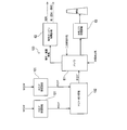
- FIG. 1 is an overall conceptual diagram of an RDF-fired power generation system including a fuel storage facility according to an embodiment of the present invention. It is a conceptual diagram which shows the structure of a fuel manufacturing part. It is a conceptual diagram which shows the structure upstream from the primary storage tank of a fuel long-term storage part. It is a conceptual diagram which shows the structure of the downstream from the primary storage tank of a fuel long-term storage part. It is a block diagram which shows the control structure of a fuel long-term storage part. It is a figure explaining the combustion range of methane. It is a flowchart which shows the flow of control of the RDF injection
- the waste-derived solid fuel storage facility according to the present invention (hereinafter also simply referred to as “fuel storage facility”) is a waste-derived solid fuel that contains a large amount of organic matter produced from waste and is easy to ferment for a long time (for example, It is equipment for storage (from several weeks to several months).
- fuel storage facility is a waste-derived solid fuel that contains a large amount of organic matter produced from waste and is easy to ferment for a long time (for example, It is equipment for storage (from several weeks to several months).
- FIG. 1 is an overall conceptual diagram of an RDF-fired power generation system including a fuel storage facility according to an embodiment of the present invention, and arrows in the figure indicate the flow of materials. Further, in the same figure, a description regarding a fine auxiliary device not directly related to the invention is omitted.
- the RDF-fired power generation system 1 mainly includes a fuel production unit 3, a temporary fuel storage unit 4, a long-term fuel storage unit 5, and a power generation unit 6.
- This RDF-fired power generation system 1 is a waste solidified fuel (hereinafter referred to as “RDF”) referred to as municipal solid waste (hereinafter referred to as “MSW; Municipal Solid Waste”). Is a system that generates electricity using heat generated by the combustion of RDF.
- the temporary fuel storage unit 4 and the long-term fuel storage unit 5 are adjacent to the power generation unit 6.
- the fuel production unit 3 may be adjacent to or separated from the power generation unit 6.
- a plurality of fuel production units 3 may exist for one power generation unit 6.
- the fuel manufacturing unit 3 includes equipment for manufacturing a fluff RDF (fluff-shaped RDF) from the MSW.
- FIG. 2 is a conceptual diagram of the fuel production unit 3, and the arrows in the figure indicate the flow of substances.
- the fuel production unit 3 mainly includes an MSW storage pit 31, a primary crusher 32, a sorter 33, and a secondary crusher 34.
- the MSW storage pit 31 is for temporarily storing the collected MSW.
- the MSW storage pit 31 has, for example, a capacity that can accommodate up to 5 days of MSW.
- the primary crusher 32 tears a plastic bag or a cloth-like substance in the MSW or crushes a large solid matter so that the sorting machine 33 can remove foreign matters and incombustibles.
- the sorter 33 is for sorting and removing incombustibles from the MSW. This incombustible material includes stones, concrete fragments, metals, and the like.
- the secondary crusher 34 is for further finely crushing the MSW from which incombustible materials and the like have been sorted and removed to a required size.
- the collected MSW is first carried into the MSW storage pit 31 and temporarily stored. Then, the MSW stored in the MSW storage pit 31 is sequentially put into the primary crusher 32 and roughly crushed. The MSW that has been primarily crushed is subjected to sorting and removal of non-combustible material by the sorter 33 and then fed into the secondary crusher 34. The MSW made of combustible material charged into the secondary crusher 34 is further finely crushed by the secondary crusher 34 to become a fluff RDF (fluff-like RDF). The RDF thus manufactured has a flat plate shape of 50 to 150 mm square. (Temporary fuel storage 4) The temporary fuel storage unit 4 includes a fuel storage 36 for storing RDF.
- the RDF manufactured by the fuel manufacturing unit 3 is carried into the fuel storage 36 and temporarily stored therein.
- the period during which the RDF is stored in the fuel storage 36 is generally several days or at most about seven days in consideration of the volume of the fuel storage 36 and the safety aspect during storage.
- the RDF stored in the fuel storage 36 is sent to the power generation unit 6 when the power generation unit 6 is in operation. Further, when the power generation unit 6 is not in operation or when the total heat amount of the manufactured RDF exceeds the heat amount of the optimum operation base of the power generation unit 6, it is stored for a period that can be stored in the fuel storage 36. When there is surplus RDF that must be stored, the RDF stored in the fuel storage 36 corresponding to the surplus RDF is sent to the long-term fuel storage unit 5.
- the power generation unit 6 is a power generation facility group for generating power by burning RDF.
- the power generation unit 6 mainly includes a boiler 61 that is an RDF combustion facility, a steam turbine power generation facility 62 to which high-pressure and high-temperature steam is fed from the boiler 61, and harmful substances contained in exhaust gas from the boiler 61.
- An exhaust gas treatment facility 63 to be removed is provided.
- the boiler 61 of the electric power generation part 6 which concerns on this Embodiment is a RDF fired boiler, it may replace with this and may be a coal fired boiler. In this case, RDF is used as an auxiliary fuel for a coal-fired boiler.
- RDF stored in the fuel storage 36 of the temporary fuel storage unit 4 is charged.
- the heat generated by the combustion of RDF in the combustion chamber 61a of the boiler 61 is recovered by heat recovery water flowing through the heat recovery device 61b and steam overheating.
- the heat recovery unit 61b and the steam turbine power generation facility 62 are connected to each other through a steam discharge path 68 configured by piping or the like.
- the steam that has recovered the combustion heat of the RDF and has become high temperature and high pressure is sent to the steam turbine power generation facility 62 through the steam discharge path 68.
- power is generated by a generator that rotates the turbine with steam and converts this rotational force into electric power.
- a primary combustion air supply path 65, a secondary combustion air supply path 66, an activation fuel supply path 67, and an exhaust path 69 are connected to the combustion chamber 61 a of the boiler 61.
- the primary combustion air supply path 65 is configured by piping, a blower, and the like that connect the combustion chamber 61 a of the boiler 61 and the primary combustion air source (external), and the combustion of the boiler 61 from the primary combustion air source through the primary combustion air supply path 65.
- Primary combustion air for combustion is supplied to the chamber 61a.
- the secondary combustion air supply path 66 is composed of a pipe connecting the combustion chamber of the boiler 61 and the secondary combustion air source (external), a blower, and the like, and to the combustion chamber 61a of the boiler 61 through the secondary combustion air supply path 66. Secondary combustion air for combustion is supplied.
- the startup fuel supply path 67 is configured by piping or the like that connects the combustion chamber of the boiler 61 and the startup fuel source. When the boiler 61 is started up, the startup of the boiler to the combustion chamber 61a of the boiler 61 through the startup fuel supply path 67 is performed. Fuel is supplied.
- the exhaust passage 69 is configured by piping or the like that connects the combustion chamber 61 a of the boiler 61 and the exhaust gas treatment facility 63.
- FIG. 3 is a conceptual diagram showing a configuration upstream of the primary storage tank of the fuel long-term storage unit, and FIG.
- FIG. 4 is a conceptual diagram showing a configuration downstream of the primary storage tank of the fuel long-term storage unit. 3 and 4, the substance flow is indicated by arrows.
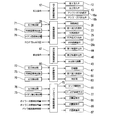
- FIG. 5 is a block diagram showing a control configuration of the long-term fuel storage unit 5.
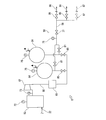
- the fuel long-term storage unit 5 mainly includes a charging device 51, a fermenter 52, a primary storage tank 53, a secondary storage tank 54, a residue discharge device 55, and a compressor 57. And a biogas supply facility 59.
- the charging device 51 is for charging RDF from the fuel storage 36 of the temporary fuel storage unit 4 to the fermenter 52.
- the input device 51 includes a fuel input tank 11 provided between the fuel storage 36 and the input port 18 of the fermenter 52. Between the fuel storage 36 and the fuel charging tank 11 and between the fuel charging tank 11 and the fermenter 52 are connected via various conveyors or pipes. Between the fuel storage 36 and the fuel charging tank 11, a first charging valve 12 that partitions these spaces and restricts the movement of the RDF from the fuel storage 36 to the fuel charging tank 11 is provided. Between the fuel charging tank 11 and the fermenter 52, there is provided a second charging valve 13 that partitions these spaces and restricts the movement of the RDF from the fuel charging tank 11 to the fermentation tank 52.
- an inert gas supply path 15 for supplying an inert gas from an inert gas source 14 is connected to the fuel supply tank 11, and an assist gas supply valve 16 a is provided in the inert gas supply path 15. It has been. Further, the fuel input tank 11 is provided with an inert gas discharge path 11a for discharging an inert gas as an assist gas from the fuel input tank 11, and the assist gas is supplied to the inert gas discharge path 11a. A valve 16a is provided. As shown in FIG. 5, the opening / closing operations of the first closing valve 12, the second closing valve 13, the assist gas supply valve 16 a and the assist gas discharge valve 16 b are controlled by the closing device controller 17.
- the input device control unit 17 opens the first input valve 12 for a time corresponding to the RDF input amount. Then, the RDF moves from the fuel storage 36 to the fuel input tank 11. Subsequently, the charging device controller 17 opens the second charging valve 13. Thereby, the RDF in the fuel charging tank 11 falls to the fermenter 52 by its own weight.
- the input device control unit 17 opens the assist gas supply valve 16 a and the assist gas discharge valve 16 b, and converts the RDF into the fermenter 52 by the inert gas supplied to the fuel input tank 11 through the inert gas supply path 15.
- the charging device controller 17 closes the second charging valve 13, the assist gas supply valve 16a, and the assist gas discharge valve 16b.
- the fermenter 52 is an anaerobic fermenter that anaerobically ferments RDF in an anaerobic atmosphere for about 15 to 20 days.
- the fermenter 52 is provided with a moving device 20 for moving the RDF from the charging side 52a with the charging port 18 to the discharging side 52b with the discharging port 19.
- the moving device 20 may be in any form as long as it can be moved from the input side 52a to the discharge side 52b, but FIG. 3 illustrates the moving device 20 provided with rotating blades.
- the moving device 20 includes a plurality of rotor blades arranged in the RDF transport direction from the input side 52a to the discharge side 52b, and a rotor blade drive unit that rotationally drives the rotor blades.
- the RDF dropped to the charging side 52a of the fermenter 52 is sequentially sent out to the discharge side 52b by the rotating rotor blades.
- the moving speed and moving amount of RDF can be controlled by adjusting the rotating speed and rotating frequency of the rotor blades.
- a biogas discharge port 21 is opened at the upper part of the discharge side 52b of the fermenter 52.
- the biogas discharge port 21 is connected to the primary storage tank 53 via the biogas first flow path 22.
- a pressure detector 71 that detects the pressure of the biogas that passes through the biogas first flow path 22
- an oxygen concentration detector 78 that also detects the oxygen concentration, and a methane concentration are also detected.
- a methane concentration detector 79 is provided.
- a first inflow control valve 23 for opening and closing the biogas first flow path 22 is provided downstream of the detectors 71, 78, and 79 in the biogas first flow path 22. By opening and closing the first inflow control valve 23, communication and blocking between the fermenter 52 and the primary storage tank 53 are switched.
- Atmospheric radiation that allows the inside of the fermenter 52 to communicate with the outside (atmosphere) on the downstream side of the detectors 71, 78, 79 of the biogas first flow path 22 and upstream of the first inflow control valve 23.
- the path 24 branches from the biogas first flow path 22.
- An air diffusion valve 25 is provided in the air diffusion path 24.
- an inert gas supply port 26 is provided on the charging side 52 a of the fermenter 52.
- the inert gas supply port 26 is connected to the inert gas source 14 via the inert gas supply path 15.
- An inert gas source valve 27 is provided in the inert gas supply path 15. This inert gas main valve 27 is opened together with the atmospheric diffusion valve 25 when the air in the fermenter 52 is replaced with an inert gas.
- the inert gas is supplied into the fermenter 52 through the inert gas supply port 26, and the air in the fermenter 52 is discharged through the atmospheric air diffusion path 24, so that the air in the fermenter 52 is inactivated. Replaced with active gas.
- a water supply device 29 for supplying water to the fermenter 52 is provided on the input side 52a of the fermenter 52 so that the water content of the RDF input to the fermenter 52 is suitable for anaerobic fermentation.
- the water supply device 29 includes a water supply pipe 29b that connects the water source 29a and the fermentation tank 52, and a water supply adjustment valve 29c that is provided in the water supply pipe 29b and adjusts the amount of water supplied to the fermentation tank 52. Yes.
- the fermenter 52 and the ambient air release valve 25, the first inflow control valve 23, the inert gas source valve 27, and the movement device 20 provided in the vicinity thereof are operated by the fermenter controller 28 with detectors 71, 78, and 79. It is controlled based on the detection signal.
- the operation of the water supply adjustment valve 29c of the water supply device 29 is such that the RDF in the fermenter 52 is anaerobic based on the RDF-containing water content measured in the RDF manufacturing process and the RDF input amount from the fuel input tank 11. It is controlled by the fermenter controller 28 so that the water content is suitable for fermentative fermentation.
- the RDF that has been input into the fermenter 52 through the input port 18 by the input device 51 falls to the input side 52 a of the moving device 20.
- the RDF in the fermenter 52 is sequentially transferred to the downstream by the moving device 20, and moves from the input side 52a to the discharge side 52b over a predetermined fermentation period (about 15 to 20 days in this case).
- a predetermined fermentation period about 15 to 20 days in this case.
- anaerobic fermentation of organic matter contained in RDF proceeds, biogas is generated, and RDF is reduced in volume and weight.
- the composition of biogas produced by RDF fermentation is approximately 60% methane gas and 40% carbon dioxide.
- the generation amount and composition of biogas vary depending on the amount and type of organic substances contained in RDF, and the generation amount also varies depending on the degree of fermentation.
- This RDF fermentation residue is composed of an unfermented volatile component in the solid content of RDF and a non-fermented component of RDF, and includes organic residues, woody residues, and vinyl residues.
- unfermented or RDF in the middle of fermentation may be mixed in the fermentation residue, and these are collectively referred to as the fermentation residue.
- the fermentation residue is sent out to the discharge port 19 by the moving device 20 and is discharged out of the fermentation tank 52 from the discharge port 19. The fermentation residue is greatly reduced in volume and reduced compared to the original RDF.
- the residue discharge device 55 is for collecting the fermentation residue in the fermenter 52 and dehydrating and removing the digestive juice and the digestive juice contained in the fermentation residue.
- the residue discharge device 55 mainly includes a residue storage tank 41 connected to the discharge port 19 of the fermentation tank 52, a digestion liquid dehydration removal device 43 connected to the residue storage tank 41 via a residue feed path 42, and a residue A drainage pit 46 for storing the digested liquid collected from the residue by the storage tank 41 and the digested liquid dehydration and removal device 43 is provided.
- a first residue discharge valve 44 is provided that partitions these and restricts the movement of the fermentation residue to the residue storage tank 41.
- a second residue discharge valve 45 is provided between the residue storage tank 41 and the residue supply path 42 for partitioning these and regulating the movement of the fermentation residue to the residue supply path 42.
- the operations of the first residue discharge valve 44, the second residue discharge valve 45, and the digestive fluid dehydration removal apparatus 43 are controlled by a residue discharge apparatus control unit 47.
- Residue discharge device control unit 47 receives fermentation residue discharge instruction input via a control panel (not shown), and opens first residue discharge valve 44 for a predetermined first discharge time.
- the first discharge time is set by the moving speed of the substance in the fermenter 52 by the moving device 20 and the amount of fermentation residue.
- the first residue discharge valve 44 is opened, the fermentation residue in the fermentation tank 52 is introduced into the residue storage tank 41 through the discharge port 19 by the moving device 20.
- the residue storage tank 41 the digested liquid is separated from the fermentation residue, and the digested liquid separated from the fermentation residue is drained to the drain pit 46.
- the residue discharge device control unit 47 opens the second residue discharge valve 45 for a predetermined second discharge time in a state where the digested liquid of the fermentation residue is removed to some extent.
- the second discharge time is set by the amount of fermentation residue.
- the fermentation residue whose volume has been reduced, reduced, and dehydrated by the residue discharge device 55 is transported from the digestive liquid dehydration removal device 43 to the MSW storage pit 31 of the fuel production unit 3 and reused as a raw material for RDF.
- the fermentation residue is conveyed to the MSW storage pit 31 of the fuel production unit 3 that is closest to the fuel long-term storage unit 5.
- the flow of biogas generated in the fermenter 52 will be described.
- many portions in the fermenter 52 are in an “empty” state, and the portions are filled with air. Therefore, the gas flowing out from the fermenter 52 to the biogas first flow path 22 in the initial stage of RDF charging becomes a mixed gas of the biogas generated by RDF fermentation and the air remaining in the fermenter 52.
- Methane gas the main component of biogas generated by anaerobic fermentation, is a flammable gas. According to the mixing ratio of methane gas and oxygen in biogas, supply of combustion oxygen from the outside as long as biogas is the source of fire There is a risk of explosive combustion without exposure.
- the fermenter control unit 28 detects the composition of the outflow gas flowing out from the fermenter 52 to the biogas first flow path 22 using the detectors 71, 78, and 79, and mixes oxygen and methane gas in the outflow gas. When the ratio is within the combustion range, it is determined to be “uncompressible”, and when it is outside the combustion range, it is determined to be “compressible”. Then, the fermenter control unit 28 opens the first inflow control valve 23 when the mixing ratio of oxygen and methane gas in the effluent gas from the fermenter 52 is outside the combustion range, and sends the effluent gas to the primary storage tank 53. Control to send.
- the phenomenon in which the mixing ratio of oxygen and methane gas in the effluent gas from the fermenter 52 falls within the combustion range is significant when RDF is started to be introduced into the fermenter 52. To avoid this phenomenon, RDF It is desirable to replace the air in the fermenter 52 with an inert gas before introducing the fermenter into the fermenter 52.
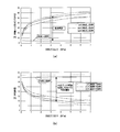
- FIG. 6 (a) is a graph showing the combustion upper limit value and the combustion lower limit value of a mixed gas of natural gas and air, where the vertical axis represents the natural gas concentration in the air, and the horizontal axis represents the pressure of the natural gas.
- the upper limit of combustion of natural gas at atmospheric pressure is 15.0 [volume% in air]
- the lower limit of combustion is 5.0 [volume% in air]. That is, the combustion range of natural gas at atmospheric pressure is 5.0 to 15.0 [volume% in air].
- FIG. 6 (b) is obtained by converting the combustion upper limit value and the combustion lower limit value of the mixed gas of natural gas and air shown in FIG. 6 (a) into the relationship between the oxygen concentration and the pressure of the natural gas.
- the main component of natural gas is methane (about 85-95%).
- the composition of biogas is approximately 60% methane and 40% carbon dioxide.
- natural gas is different from methane gas, but safety can be secured even if the value of the combustion range of natural gas is used as the value of the combustion range of methane gas in examining the combustion range of the outflow gas from the fermenter 52. . Therefore, in the following, in examining the combustion range of the effluent gas from the fermenter 52 (particularly, the lower limit of combustion), the natural gas in FIG. 6 (a) and FIG. The indicated data will be used.
- the discharge pressure of the compressor 57 described later is 5 MPa and the temperature of the compressed biogas is 300 ° C.
- the lower limit value of the oxygen concentration when the pressure of methane gas is 5 MPa and the temperature is 300 ° C. is 8 to 9%. Therefore, in consideration of the safety factor, if the outflow gas from the fermenter 52 is sent to the primary storage tank 53 as a biogas with an oxygen concentration of 8% or less, even if this biogas is compressed by the compressor 57 The mixing ratio of oxygen and methane gas is outside the combustion range.
- the upper limit of the oxygen concentration when the pressure of methane gas is 5 MPa and the temperature is 300 ° C. is approximately 20%. However, since the oxygen concentration in the air is about 21%, it is safe not to compress the outflow gas exceeding the upper limit value of the oxygen concentration in consideration of the safety factor. From the above, when the discharge pressure of the compressor 57 is 5 MPa and the temperature of the biogas after compression is 300 ° C., out of the outflow gas from the fermenter 52 based on the data in FIGS. Those having an oxygen concentration exceeding 8% are considered to be within the combustion range, and those having an oxygen concentration of 8% or less are considered to be outside the combustion range.
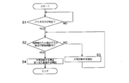
- FIG. 7 is a flowchart showing a flow of control of the fermenter control unit 28 at the initial stage of RDF charging.
- the first inflow control valve 23 and the air release valve 25 are closed, and the fermenter 52 is filled with initial air, so that it is in an aerobic state. It has become. Therefore, aerobic fermentation is performed in the fermenter 52 for a while after the start of fermentation, but as the aerobic fermentation proceeds, the oxygen in the fermenter 52 is consumed, thereby making the fermenter 52 anaerobic and anaerobic fermentation. Migrate to As shown in FIG.
- the fermenter control unit 28 detects that biogas is generated based on the pressure in the fermenter 52 detected by the pressure detector 71 (YES in step S1), and the atmospheric emission valve. 25 is released (step S3).
- the effluent gas from the fermenter 52 is initially composed of a methane gas amount of 0% and an air amount of 100%, and the mixing ratio of oxygen and methane gas in the effluent gas is within the combustion range (here, less than the upper combustion limit). It is.
- outflow gas from the fermenter 52 that is unsuitable for compression that is, a mixture ratio of oxygen and methane gas within the combustion range
- the fermenter control unit 28 determines that the mixing ratio of oxygen and methane gas in the effluent gas from the fermenter 52 is outside the combustion range.
- step S2 the atmospheric diffusion valve 25 is closed and the first inflow control valve 23 is opened (step S4).
- step S4 most of the outflow gas from the fermenter 52 is biogas.
- the primary storage tank 53 is a biogas storage tank for storing biogas sent from the fermenter 52 via the biogas first flow path 22.
- the biogas sent from the fermenter 52 to the primary storage tank 53 varies depending on the amount of RDF input into the fermenter 52 and the fermentation state after input.
- the primary storage tank 53 is a buffer tank for storing the biogas flowing out from the fermenter 52 and preventing an abnormal increase in the pressure in the fermenter 52.
- the primary storage tank 53 is also a buffer tank that buffers an imbalance between the suction flow rate of the compressor 57 and the amount of biogas generated from the fermenter 52. Therefore, it is desirable that the primary storage tank 53 has a sufficient capacity.
- the primary storage tank 53 is connected to one or a plurality of secondary storage tanks 54 through piping that forms the biogas second flow path 56.
- the biogas second flow path 56 is provided with a compressor 57, a cooler 83, and a second inflow control valve 80 to the secondary storage tank 54 in order from the upstream side.
- a pressure detector 72 for detecting the pressure in the primary storage tank 53, and the biogas in the primary storage tank 53
- An oxygen concentration detector 73 for detecting the oxygen concentration is provided.
- the compressor control unit 60 receives detection signals from the pressure detector 72 and the oxygen concentration detector 73, and the biogas in the primary storage tank 53 is appropriately compressed by the compressor 57 and sent to the secondary storage tank 54. In addition, the compressor 57 and the second inflow control valve 80 are controlled so that the pressure in the primary storage tank 53 does not become negative.
- the oxygen concentration detector 73 detects the oxygen concentration in the biogas to be compressed, and the compressor control unit 60 determines whether the biogas can be compressed based on the detection result.
- the primary storage tank 53 is connected to two secondary storage tanks 54, but the number of secondary storage tanks 54 is not limited to this.
- the number, capacity and internal pressure of the secondary storage tank 54 are determined based on the amount of RDF to be processed and the amount of biogas generated during the storage period.
- the pressure of the biogas in the secondary storage tank 54 is preferably 2 to 5 MPa.
- the biogas pressure in the secondary storage tank 54 may be 2 to 5 MPa or more.
- the biogas generated along with the anaerobic fermentation of RDF is balanced with the pressure in the fermenter 52 in the primary storage tank 53, compressed by the compressor 57, cooled by the cooler 83, It is stored in the secondary storage tank 54. Since the biogas stored in the secondary storage tank 54 is reduced in volume by compression, the space for storing the biogas can be reduced. Furthermore, since biogas is a gas, it is easier to manage the state compared to storing RDF that is easily fermented as it is, and handling during storage is easy.
- the biogas stored in the secondary storage tank 54 is supplied to the boiler 61 of the power generation unit 6 by the biogas supply equipment 59.
- a biogas supply path 58 for supplying biogas to the boiler 61 is connected to the secondary storage tank 54.
- a tank opening / closing valve 81, a methane concentration detector 75 for detecting the methane concentration of the biogas, and a biogas supply source valve 77 are provided in this order from the upstream side.
- the biogas supply path 58 branches in two directions on the downstream side of the methane concentration detector 75, and the downstream side from this bifurcated branch is a primary combustion air supply path 65 and a secondary combustion air supply path 66 to the boiler 61, respectively. It is connected.
- flow rate adjusting valves 85 and 86 for adjusting the amount of biogas supplied to the supply paths 65 and 66 are provided. It has been.
- the biogas supply control unit 70 detects the pressure detector 76 of the secondary storage tank 54, the detection signal of the methane concentration detector 75, the primary or secondary combustion air amount to the boiler 61, and the combustion of the boiler 61. Based on the load information, the operations of the tank opening / closing valve 81, the biogas supply source valve 77, and the flow rate adjusting valves 85, 86 are controlled.
- the biogas supply control unit 70 opens the tank opening / closing valve 81 and the biogas supply source valve 77 and adjusts the flow rate of the biogas by the flow rate adjustment valve 86.
- the flow rate of the biogas is adjusted by the flow rate adjusting valve 86.
- the flow rate of biogas is such that the mixing ratio of air and methane gas in the mixture of secondary combustion air and biogas is to prevent abnormal combustion in the air and biogas mixed gas supply channel. It adjusts so that it may become out of a combustion range (mixing ratio below the lower limit of combustion shown in Drawing 6 (a)).
- the biogas supply control unit 70 controls the opening and closing and the opening degree of the flow control valve 86 based on the amount of secondary combustion air to the boiler 61, the methane concentration of the biogas, and the combustion load information of the boiler 61. .
- the biogas is sent exclusively to the secondary combustion air supply path 66.
- a boiler load increase command is issued based on the combustion load information of the boiler 61, it is difficult to increase the amount of RDF input, and the amount of biogas mixed into the secondary combustion air is limited by the combustion lower limit value
- the biogas is also sent to the primary combustion air supply path 65.
- the biogas supply control unit 70 adjusts the opening degree of the flow rate adjustment valve 85. Again, in order to make the mixing ratio of air and methane gas in the mixture of primary combustion air and biogas out of the combustion range (mixing ratio below the lower combustion limit shown in FIG.
- the opening / closing and opening of the flow rate adjustment valve 85 are adjusted to adjust the amount of biogas supplied to the primary combustion air supply path 65. Is done.
- the biogas when the calorie of the biogas stored in the secondary storage tank 54 is sufficiently high to be used as the startup fuel for the boiler 61, the biogas is used as the startup fuel for the boiler 61 or its auxiliary fuel. can do.
- a flow path connected to the startup fuel supply path 67 in parallel with the flow path connected to the primary combustion air supply path 65 and the secondary combustion air supply path 66 is provided.
- a flow rate adjusting valve 87 is provided in this flow path.
- the biogas supply control unit 70 opens the tank opening / closing valve 81 and the biogas supply source valve 77 when starting the boiler 61 and adjusts the opening degree of the flow rate adjusting valve 87 to start the biogas from the boiler 61.
- the fuel is supplied to the fuel supply passage 67.
- biogas is used as the starting fuel for the boiler 61
- the pressure of the biogas in the secondary storage tank 54 can be maintained even after the boiler 61 is started, as required by the starting burner for the boiler 61.
- the pressure is desirable.
- RDF is manufactured from the MSW recovered by the fuel manufacturing unit 3.
- the manufactured RDF is primarily stored in the fuel storage 36 of the temporary fuel storage unit 4.
- the boiler 61 of the power generation unit 6 When the boiler 61 of the power generation unit 6 is operating, the RDF stored in the fuel storage 36 is supplied to the boiler 61 as fuel.
- RDF is burned by the boiler 61, the heat is recovered to generate high-temperature and high-pressure steam, and power is generated by rotating the turbine of the steam turbine power generation facility 62.
- the boiler 61 of the power generation unit 6 is stopped or when it is necessary to store the RDF for a long time (for example, one week or more), the RDF stored in the fuel storage 36 is first stored in the fuel storage 36. Are sequentially sent to the long-term fuel storage unit 5.
- RDF undergoes anaerobic fermentation to produce biogas and fermentation residues.
- the fermentation residue produced by the anaerobic fermentation of RDF is discharged from the fermenter 52 and the water is removed, and then transferred to the fuel production unit 3 and used as a raw material for RDF.
- the biogas generated by the anaerobic fermentation of RDF is sent to the primary storage tank 53, compressed by the compressor 57, cooled by the cooler 83, and then sent to the secondary storage tank 54 for storage.
- the biogas stored in the secondary storage tank 54 is supplied to the boiler 61 during operation of the power generation unit 6 and used as fuel or auxiliary fuel.
- the boiler 61 immediately after starting becomes a mixed combustion operation of RDF and biogas.
- the boiler 61 enters the RDF combustion operation.
- RDF is not sent from the temporary fuel storage unit 4 to the long-term fuel storage unit 5 when the power generation unit 6 is in operation, but RDF is also sent from the temporary fuel storage unit 4 to the long-term fuel storage unit 5 during operation of the power generation unit 6. It can also be sent.
- the RDF is stored in the long-term fuel storage unit 5 while supplying the RDF from the temporary fuel storage unit 4 to the power generation unit 6 in order to balance the supply amount of RDF to the boiler 61 of the power generation unit 6 and the demand amount. can do. In this way, the space for RDF storage including the temporary fuel storage unit 4 and the long-term fuel storage unit 5 can be further reduced. Furthermore, it becomes possible to balance supply and demand between the RDF manufactured from the MSW and the RDF consumed by the boiler 61.
- the RDF-fired power generation system 1 stores surplus RDF by changing the form into biogas and fermentation residue. Since biogas is a gas, it is easier to manage long-term storage and long-term storage in a sealed space than when solid RDF is stored in a conventional RDF storage. Moreover, the volume of the biogas which is a gas can be easily reduced by compression, and the storage space can be reduced by storing the biogas in a compressed state. In addition, since the fermentation residue is dehydrated, reduced in volume, and reduced in volume, the space for storing solid matter can be reduced as compared with the case of storing RDF, and management of storage is easy.
- the long-term fuel storage unit 5 of the RDF-fired power generation system 1 it is possible to reduce the space for storing the RDF and to prevent the methane gas fire that occurs due to the aerobic fermentation during the long-term storage of the RDF. it can.
- the form of RDF is changed to biogas and fermentation residue, biogas is reused as fuel in the boiler 61, and the fermentation residue is used as a raw material for RDF, so the energy of RDF is fully utilized.
- the long-term fuel storage unit 5 of the RDF-fired power generation system 1 it is possible to store RDF that is easily fermented in a dry environment and a high-temperature and humid environment, and it is easy to ferment regardless of the storage environment. Can be stored stably.
- FIG. 8 is a conceptual diagram showing a configuration upstream of the primary storage tank of the fuel long-term storage unit according to the modification
- FIG. 9 is a concept showing a configuration downstream of the primary storage tank of the fuel long-term storage unit according to the modification.
- FIG. The modified example of the fuel long-term storage unit 5 shown in these drawings is a reserve storage tank 92 connected to the fermenter 52 via the biogas third flow path 91 as compared with the fuel long-term storage unit 5 shown in FIG.
- the biogas third flow path 91 is provided with a third inflow control valve 93 that is controlled to be opened and closed by the fermenter controller 28.
- the auxiliary storage tank 92 is provided with an air diffusion path 24 and an air diffusion valve 25.
- the preliminary storage tank 92 is connected to the primary combustion air supply path 65 and the secondary combustion air supply path 66 of the boiler 61 through the second biogas supply path 95.
- the second biogas supply passage 95 has a low-pressure blower 96 for supplying the biogas in the auxiliary storage tank 92, a methane concentration detector 84, and biogas supplied to the combustion air supply paths 65 and 66.
- Flow rate adjusting valves 97 and 98 for adjusting the flow rate are provided.
- the fermenter control unit 28 has a mixing ratio of oxygen and methane gas of the outflow gas from the fermenter 52 based on the detection values of the concentration detector 78 and the methane concentration detector 79.
- the third inflow control valve 93 is opened. Thereby, the mixing ratio of methane gas and oxygen is within the combustion range, and the outflow gas (mixed gas of biogas and air) unsuitable for compression is sent to the preliminary storage tank 92 and stored in the preliminary storage tank 92. .
- the biogas stored in the preliminary storage tank 92 without being compressed is stored in the primary combustion air supply path 65 and the secondary combustion air supply path 66 through the second biogas supply path 95 by the low pressure blower 96 when the power generation unit 6 is operated. It is pumped to at least one and used as fuel for the boiler 61.
- the RDF-fired power generation system 1 is a system that generates power using RDF manufactured from MSW as fuel, and this is used as fuel for biomass-derived waste-derived solid fuel manufactured from biomass-based waste. It can also be applied to a power generation system.
- the present invention is applied to the RDF-fired power generation system 1 for biomass waste by replacing MSW with biomass waste and RDF with biomass waste-derived solid fuel. Can be explained.
- the present invention is useful for storing a fermentable waste-derived solid fuel such as fluff RDF and biomass-based waste-derived solid fuel in a stable state for a long period of time.
Landscapes
- Chemical & Material Sciences (AREA)
- Engineering & Computer Science (AREA)
- Organic Chemistry (AREA)
- Health & Medical Sciences (AREA)
- Life Sciences & Earth Sciences (AREA)
- Oil, Petroleum & Natural Gas (AREA)
- Wood Science & Technology (AREA)
- Zoology (AREA)
- Bioinformatics & Cheminformatics (AREA)
- General Engineering & Computer Science (AREA)
- Genetics & Genomics (AREA)
- Mechanical Engineering (AREA)
- General Chemical & Material Sciences (AREA)
- Microbiology (AREA)
- Sustainable Development (AREA)
- Biomedical Technology (AREA)
- General Health & Medical Sciences (AREA)
- Biochemistry (AREA)
- Biotechnology (AREA)
- Chemical Kinetics & Catalysis (AREA)
- Molecular Biology (AREA)
- Clinical Laboratory Science (AREA)
- Combustion & Propulsion (AREA)
- Solid Fuels And Fuel-Associated Substances (AREA)
- Processing Of Solid Wastes (AREA)
Abstract
Description
(燃料製造部3)
燃料製造部3は、MSWからフラフRDF(フラフ状のRDF)を製造するための設備を備えている。図2は、燃料製造部3の概念図であり、図中の矢印は物質の流れを示している。同図に示すように、燃料製造部3は主に、MSW貯蔵ピット31と、一次破砕機32と、選別機33と、二次破砕機34とを備えている。MSW貯蔵ピット31は、収集されてきたMSWを一時貯蔵するためのものである。このMSW貯蔵ピット31は、例えば、最大で5日分のMSWを収容できる容量を有する。一次破砕機32は、選別機33で異物や不燃物を除去可能とするために、MSW中のビニール袋や布状の物質を引き破ったり、大きな固形物を破砕したりするものである。選別機33は、MSWから不燃物等を選別除去するためのものである。この不燃物等には、石やコンクリートの破片、金属類などが含まれている。二次破砕機34は、不燃物等が選別除去されたMSWを要求された寸法となるまで更に細かく破砕するためのものである。
(燃料一時貯蔵部4)
燃料一時貯蔵部4は、RDFを貯蔵するための燃料貯蔵庫36を備えている。燃料製造部3で製造されたRDFは燃料貯蔵庫36へ搬入され、ここで一時的に貯蔵される。燃料貯蔵庫36でRDFが貯蔵される期間は、燃料貯蔵庫36の容積と貯蔵中の安全面を考慮して、一般には数日、長くとも7日程度である。燃料貯蔵庫36に貯蔵されているRDFは、発電部6の稼働時には発電部6へ送られる。また、発電部6が稼動を停止しているときや製造されたRDFの総熱量が発電部6の最適運転ベースの熱量を上回るときなどの、燃料貯蔵庫36で貯蔵可能な期間を超えて貯蔵しなればならない余剰のRDFがあるときは、その余剰分相当の燃料貯蔵庫36に貯蔵されたRDFが燃料長期貯蔵部5へ送られる。
(発電部6)
発電部6は、RDFを燃焼して発電を行うための発電設備群である。発電部6は主に、RDFの燃焼設備であるボイラ61と、ボイラ61から高圧且つ高温の蒸気が送給される蒸気タービン発電設備62と、ボイラ61からの排気ガス中に含まれる有害物を除去する排気ガス処理設備63とを備えている。なお、本実施の形態に係る発電部6のボイラ61は、RDF焚きボイラであるが、これに代えて石炭焚きボイラであってもかまわない。この場合、RDFは石炭焚きボイラの補助燃料として利用される。
(燃料長期貯蔵部5)
続いて、燃料長期貯蔵部5について詳細に説明する。燃料長期貯蔵部5は、燃料一時貯蔵部4での貯蔵可能期間を越えてRDFを貯蔵するための設備群である。燃料長期貯蔵部5において、RDFはバイオガスと発酵残渣という減容且つ減量された状態で貯蔵されることとなる。図3は燃料長期貯蔵部の一次貯蔵タンクより上流側の構成を示す概念図であり、図4は燃料長期貯蔵部の一次貯蔵タンクより下流側の構成を示す概念図である。図3,4では、物質の流れが矢印で示されている。また、図5は、燃料長期貯蔵部5の制御構成を示すブロック図である。図3,4に示すように、燃料長期貯蔵部5は主に、投入装置51と、発酵槽52と、一次貯蔵タンク53と、二次貯蔵タンク54と、残渣排出装置55と、圧縮機57と、バイオガス供給設備59とを備えている。
3 燃料製造部
4 燃料一時貯蔵部
5 燃料長期貯蔵部
6 発電部
20 搬送装置
22 バイオガス第1流路
23 第1流入制御弁
25 大気放散弁
31 MSW貯蔵ピット
36 燃料貯蔵庫
51 投入装置
52 発酵槽
53 一次貯蔵タンク(バイオガス貯蔵槽)
54 二次貯蔵タンク(バイオガス貯蔵槽)
55 残渣排出装置
56 バイオガス第2流路
57 圧縮機
58 バイオガス供給路
59 バイオガス供給設備
61 ボイラ
62 蒸気タービン発電設備
63 排気ガス処理設備
65 一次燃焼空気供給路
66 二次燃焼空気供給路
92 予備貯蔵タンク
Claims (22)
- 発酵しやすい廃棄物由来固形燃料を燃焼設備で燃焼する前に貯蔵するための貯蔵設備であって、
前記廃棄物由来固形燃料を嫌気性発酵させる発酵槽と、
前記廃棄物由来固形燃料の嫌気性発酵により生じるバイオガスを貯蔵するバイオガス貯蔵槽と、
前記発酵槽から前記バイオガス貯蔵槽へ前記バイオガスを送る第1流路と、
前記バイオガス貯蔵槽から前記燃料設備へ前記バイオガスを供給する供給路と備える、
廃棄物由来固形燃料の貯蔵設備。 - 前記バイオガス貯蔵槽は、前記発酵槽から前記第1流路を通じて前記バイオガスが送られる一次貯蔵槽と、前記一次貯蔵槽と第2流路で接続された二次貯蔵槽とを含み、
前記第2流路において前記一次貯蔵槽から前記二次貯蔵槽へ前記バイオガスを圧縮して送る圧縮機と、
前記第2流路において前記圧縮機で圧縮された前記バイオガスを冷却する冷却器とを備える、請求項1に記載の廃棄物由来固形燃料の貯蔵設備。 - 前記発酵槽から排出された前記廃棄物由来固形燃料の発酵済み残渣である水分および前記廃棄物由来固形燃料の発酵残渣に含まれる水分を除去する水分除去手段を備える、請求項1又は請求項2に記載の廃棄物由来固形燃料の貯蔵設備。
- 前記発酵槽から前記第1流路へ流出する流出ガスの酸素濃度を検出する酸素濃度検出器と、
前記流出ガスのメタン濃度を検出するメタン濃度検出器と、
検出された酸素濃度およびメタン濃度に基づいて、前記流出ガスの酸素とメタンガスの混合比が燃焼範囲外であるときに開弁して前記第1流路と前記バイオガス貯蔵槽とを連通させる第1制御弁とを備える、請求項1~3のいずれか一項に記載の廃棄物由来固形燃料の貯蔵設備。 - 前記発酵槽内と大気を連通させる大気放散路と、
前記酸素濃度検出器で検出された酸素濃度および前記メタン濃度検出器で検出されたメタン濃度に基づいて、前記流出ガスの酸素とメタンガスの混合比が燃焼範囲内であるときに開弁して前記大気放散路を通じて前記流出ガスを大気放散させる大気放散弁とを備える、請求項4に記載の廃棄物由来固形燃料の貯蔵設備。 - 前記発酵槽と第3流路を介して接続された予備貯蔵槽と、
前記酸素濃度検出器で検出された酸素濃度および前記メタン濃度検出器で検出されたメタン濃度に基づいて、前記流出ガスの酸素とメタンガスの混合比が燃焼範囲内であるときに開弁して前記第3流路と前記予備貯蔵槽とを連通させる第2制御弁とを備える、請求項4に記載の廃棄物由来固形燃料の貯蔵設備。 - 前記供給路は、前記バイオガス貯蔵槽で貯蔵されている前記バイオガスを、前記燃焼設備の起動用燃料として前記燃焼設備へ供給する経路を有する、請求項1~6のいずれか一項に記載の廃棄物由来固形燃料の貯蔵設備。
- 前記供給路は、前記バイオガス貯蔵槽で貯蔵されている前記バイオガスを、前記燃焼設備の一次燃焼空気供給路および二次燃焼空気供給路のうち少なくとも一方へ供給する経路を有する、請求項1~7のいずれか一項に記載の廃棄物由来固形燃料の貯蔵設備。
- 前記供給路は、前記燃焼設備へ供給される前記バイオガスが前記燃焼設備の一次燃焼空気又は二次燃焼空気と燃焼範囲外の混合比で混合するように、前記バイオガスの供給量を調整する調整手段を備えている、請求項8に記載の廃棄物由来固形燃料の貯蔵設備。
- 前記廃棄物由来固形燃料が、一般廃棄物から製造されたごみ固形化燃料である、請求項1~9のいずれか一項に記載の廃棄物由来固形燃料の貯蔵設備。
- 前記廃棄物由来固形燃料が、バイオマス系廃棄物から製造されたバイオマス廃棄物由来固形燃料である、請求項1~9のいずれか一項に記載の廃棄物由来固形燃料の貯蔵設備。
- 発酵しやすい廃棄物由来固形燃料を燃焼設備で燃焼する前に貯蔵する方法であって、
前記廃棄物由来固形燃料を嫌気性発酵槽で嫌気性発酵させるステップと、
前記廃棄物由来固形燃料の嫌気性発酵により生じるバイオガスをバイオガス貯蔵槽で貯蔵するステップとを含む、
廃棄物由来固形燃料の貯蔵方法。 - 前記バイオガスをバイオガス貯蔵槽で貯蔵するステップは、
前記発酵槽から送られてくるバイオガスを一次貯蔵槽に収容するステップと、
前記一次貯蔵槽から二次貯蔵槽へ前記バイオガスを圧縮することにより減容化して送るステップと、
前記圧縮されたバイオガスを冷却するステップと、
前記圧縮されたバイオガスを前記二次貯蔵槽で貯蔵するステップとを含む、請求項12に記載の廃棄物由来固形燃料の貯蔵方法。 - 前記発酵槽から排出される前記廃棄物由来固形燃料の発酵済み残渣である水分および前記廃棄物由来固形燃料の発酵残渣に含まれる水分を除去するステップを含む、請求項12又は請求項13に記載の廃棄物由来固形燃料の貯蔵方法。
- 前記バイオガスをバイオガス貯蔵槽で貯蔵するステップにおいて、
前記バイオガスを含む前記発酵槽から流出する流出ガスの酸素濃度およびメタン濃度を検出し、この検出結果に基づいて、前記流出ガスのうちその酸素とメタンガスの混合比が燃焼範囲外のものを前記バイオガス貯蔵槽へ貯蔵する、請求項12~14のいずれか一項に記載の廃棄物由来固形燃料の貯蔵方法。 - 前記バイオガスをバイオガス貯蔵槽で貯蔵するステップにおいて、
前記流出ガスの酸素濃度およびメタン濃度に基づいて、前記流出ガスのうちその酸素とメタンガスの混合比が燃焼範囲内のものを大気放散する、請求項15に記載の廃棄物由来固形燃料の貯蔵方法。 - 前記バイオガスをバイオガス貯蔵槽で貯蔵するステップにおいて、
前記流出ガスの酸素濃度およびメタン濃度に基づいて、前記流出ガスのうちその酸素とメタンガスの混合比が燃焼範囲内のものを前記バイオガス貯蔵槽とは異なる予備貯蔵槽へ貯蔵する、請求項15に記載の廃棄物由来固形燃料の貯蔵方法。 - 前記バイオガス貯蔵槽で貯蔵されている前記バイオガスを、前記燃焼設備の起動用燃料として前記燃焼設備へ供給するステップを更に含む、請求項12~17のいずれか一項に記載の廃棄物由来固形燃料の貯蔵方法。
- 前記バイオガス貯蔵槽で貯蔵されている前記バイオガスを、前記燃焼設備の一次燃焼空気供給路および二次燃焼空気供給路のうち少なくとも一方へ供給するステップを更に含む、請求項12~18のいずれか一項に記載の廃棄物由来固形燃料の貯蔵方法。
- 前記燃焼設備へ供給される前記バイオガスが前記燃焼設備の一次燃焼空気又は二次燃焼空気と燃焼範囲外の混合比で混合するように前記バイオガスの供給量を調整する、請求項19に記載の廃棄物由来固形燃料の貯蔵方法。
- 前記廃棄物由来固形燃料が、一般廃棄物から製造されたごみ固形化燃料である、請求項12~20のいずれか一項に記載の廃棄物由来固形燃料の貯蔵方法。
- 前記廃棄物由来固形燃料が、バイオマス系廃棄物から製造されたバイオマス系廃棄物由来固形燃料である、請求項12~20のいずれか一項に記載の廃棄物由来固形燃料の貯蔵方法。
Priority Applications (3)
| Application Number | Priority Date | Filing Date | Title |
|---|---|---|---|
| PH1/2013/501749A PH12013501749B1 (en) | 2011-03-30 | 2012-03-22 | Storage facility for waste~derived solid fuel and storage method therefor |
| MYPI2013701716A MY185426A (en) | 2011-03-30 | 2012-03-22 | Waste-derived solid fuel storage facility and storage method |
| KR1020137028653A KR101503205B1 (ko) | 2011-03-30 | 2012-03-22 | 폐기물 유래 고형 연료의 저장 설비 및 저장 방법 |
Applications Claiming Priority (2)
| Application Number | Priority Date | Filing Date | Title |
|---|---|---|---|
| JP2011076129A JP2012207901A (ja) | 2011-03-30 | 2011-03-30 | 廃棄物由来固形燃料の貯蔵設備および貯蔵方法 |
| JP2011-076129 | 2011-03-30 |
Publications (1)
| Publication Number | Publication Date |
|---|---|
| WO2012132338A1 true WO2012132338A1 (ja) | 2012-10-04 |
Family
ID=46930122
Family Applications (1)
| Application Number | Title | Priority Date | Filing Date |
|---|---|---|---|
| PCT/JP2012/001968 Ceased WO2012132338A1 (ja) | 2011-03-30 | 2012-03-22 | 廃棄物由来固形燃料の貯蔵設備および貯蔵方法 |
Country Status (5)
| Country | Link |
|---|---|
| JP (1) | JP2012207901A (ja) |
| KR (1) | KR101503205B1 (ja) |
| MY (1) | MY185426A (ja) |
| PH (1) | PH12013501749B1 (ja) |
| WO (1) | WO2012132338A1 (ja) |
Families Citing this family (3)
| Publication number | Priority date | Publication date | Assignee | Title |
|---|---|---|---|---|
| WO2014208719A1 (ja) * | 2013-06-28 | 2014-12-31 | 日本家畜貿易株式会社 | 発電装置及び牛糞を含む家畜糞の再利用システム |
| JP2019014783A (ja) * | 2017-07-04 | 2019-01-31 | 株式会社バイオエナジージャパン | バイオ燃料およびその製造方法並びに発電方法 |
| KR102445678B1 (ko) * | 2020-12-03 | 2022-09-23 | 한국석유관리원 | 석탄 저장시설로부터 메탄가스의 회수 및 자원화 방법 및 시스템 |
Citations (4)
| Publication number | Priority date | Publication date | Assignee | Title |
|---|---|---|---|---|
| JP2002362990A (ja) * | 2001-06-07 | 2002-12-18 | Fujita Corp | 液体肥料の製造方法およびそのための装置 |
| JP2003321690A (ja) * | 2002-05-01 | 2003-11-14 | Shinichi Shimose | 肉骨粉または食肉処理廃物の処理方法 |
| JP2006036849A (ja) * | 2004-07-23 | 2006-02-09 | Kobelco Eco-Solutions Co Ltd | バイオガスの処理利用システム及びバイオガスの処理利用方法 |
| JP2010209241A (ja) * | 2009-03-11 | 2010-09-24 | Unitika Ltd | メタンガス精製設備 |
-
2011
- 2011-03-30 JP JP2011076129A patent/JP2012207901A/ja not_active Withdrawn
-
2012
- 2012-03-22 MY MYPI2013701716A patent/MY185426A/en unknown
- 2012-03-22 WO PCT/JP2012/001968 patent/WO2012132338A1/ja not_active Ceased
- 2012-03-22 KR KR1020137028653A patent/KR101503205B1/ko not_active Expired - Fee Related
- 2012-03-22 PH PH1/2013/501749A patent/PH12013501749B1/en unknown
Patent Citations (4)
| Publication number | Priority date | Publication date | Assignee | Title |
|---|---|---|---|---|
| JP2002362990A (ja) * | 2001-06-07 | 2002-12-18 | Fujita Corp | 液体肥料の製造方法およびそのための装置 |
| JP2003321690A (ja) * | 2002-05-01 | 2003-11-14 | Shinichi Shimose | 肉骨粉または食肉処理廃物の処理方法 |
| JP2006036849A (ja) * | 2004-07-23 | 2006-02-09 | Kobelco Eco-Solutions Co Ltd | バイオガスの処理利用システム及びバイオガスの処理利用方法 |
| JP2010209241A (ja) * | 2009-03-11 | 2010-09-24 | Unitika Ltd | メタンガス精製設備 |
Also Published As
| Publication number | Publication date |
|---|---|
| KR20140002786A (ko) | 2014-01-08 |
| JP2012207901A (ja) | 2012-10-25 |
| PH12013501749B1 (en) | 2017-12-13 |
| MY185426A (en) | 2021-05-19 |
| KR101503205B1 (ko) | 2015-03-16 |
| PH12013501749A1 (en) | 2013-10-14 |
Similar Documents
| Publication | Publication Date | Title |
|---|---|---|
| CN102070308B (zh) | 利用水泥回转窑处理生活垃圾的设备工艺配置方法 | |
| CN101693251B (zh) | 海上船舶生活垃圾热裂解资源化处理工艺 | |
| Wilson et al. | A comparative assessment of commercial technologies for conversion of solid waste to energy | |
| CN102357516B (zh) | 市政垃圾预处理与水泥窑资源综合利用的联合工艺及其系统 | |
| CN111023114A (zh) | 一种协同处理市政污泥和餐厨垃圾的方法 | |
| CN105972604B (zh) | 一种耦合于水泥窑协同处置的生活垃圾预处置系统及方法 | |
| GB2528611A (en) | Apparatus and process for treating waste | |
| US11446719B2 (en) | Virtual landfill terminal | |
| CN101722173A (zh) | 垃圾综合处理系统 | |
| CN102980193A (zh) | 一种垃圾焚烧废气利用环保节能装置 | |
| JP2022088272A (ja) | 廃棄物処理システム、廃棄物処理方法およびペレット | |
| CN108393336A (zh) | 一种生活垃圾处理系统及其处理方法 | |
| CN201795495U (zh) | 垃圾处理系统 | |
| JP2012207901A (ja) | 廃棄物由来固形燃料の貯蔵設備および貯蔵方法 | |
| FR2863920A1 (fr) | Procede de traitement et de valorisation de dechets | |
| CN102344259A (zh) | 一种垃圾焚烧废气利用环保节能装置 | |
| CN107056106B (zh) | 一种含湿生物质燃料的悬浮催化氧化无焰燃烧装备 | |
| CN202174105U (zh) | 市政垃圾预处理与水泥窑资源综合利用的联合系统 | |
| Ahmed et al. | Use of granulated wood waste and municipal solid waste as fuel | |
| CN104668277B (zh) | 基于家庭厨余垃圾的有机浆液厌氧资源回收系统及方法 | |
| KR101074614B1 (ko) | 도심 쓰레기 집하장을 이용한 바이오 열병합 발전시스템 | |
| CN205782961U (zh) | 一种耦合于水泥窑协同处置的生活垃圾预处置系统 | |
| CN104028544A (zh) | 一种资源再利用系统 | |
| Kara et al. | The usage of refuse derived fuel from urban solid waste in cement industry as an alternative fuel | |
| CN108787705A (zh) | 城市生活垃圾处理工艺方法 |
Legal Events
| Date | Code | Title | Description |
|---|---|---|---|
| 121 | Ep: the epo has been informed by wipo that ep was designated in this application |
Ref document number: 12764345 Country of ref document: EP Kind code of ref document: A1 |
|
| DPE1 | Request for preliminary examination filed after expiration of 19th month from priority date (pct application filed from 20040101) | ||
| WWE | Wipo information: entry into national phase |
Ref document number: 12013501749 Country of ref document: PH |
|
| NENP | Non-entry into the national phase |
Ref country code: DE |
|
| WWE | Wipo information: entry into national phase |
Ref document number: 1301005609 Country of ref document: TH |
|
| ENP | Entry into the national phase |
Ref document number: 20137028653 Country of ref document: KR Kind code of ref document: A |
|
| 122 | Ep: pct application non-entry in european phase |
Ref document number: 12764345 Country of ref document: EP Kind code of ref document: A1 |