WO2012132331A1 - Rotor and rotating electrical mechanism using same - Google Patents
Rotor and rotating electrical mechanism using same Download PDFInfo
- Publication number
- WO2012132331A1 WO2012132331A1 PCT/JP2012/001949 JP2012001949W WO2012132331A1 WO 2012132331 A1 WO2012132331 A1 WO 2012132331A1 JP 2012001949 W JP2012001949 W JP 2012001949W WO 2012132331 A1 WO2012132331 A1 WO 2012132331A1
- Authority
- WO
- WIPO (PCT)
- Prior art keywords
- rotor
- rotor core
- core
- magnet
- gap
- Prior art date
Links
Images


Classifications
-
- H—ELECTRICITY
- H02—GENERATION; CONVERSION OR DISTRIBUTION OF ELECTRIC POWER
- H02K—DYNAMO-ELECTRIC MACHINES
- H02K1/00—Details of the magnetic circuit
- H02K1/06—Details of the magnetic circuit characterised by the shape, form or construction
- H02K1/22—Rotating parts of the magnetic circuit
- H02K1/27—Rotor cores with permanent magnets
- H02K1/2706—Inner rotors
- H02K1/272—Inner rotors the magnetisation axis of the magnets being perpendicular to the rotor axis
- H02K1/274—Inner rotors the magnetisation axis of the magnets being perpendicular to the rotor axis the rotor consisting of two or more circumferentially positioned magnets
- H02K1/2753—Inner rotors the magnetisation axis of the magnets being perpendicular to the rotor axis the rotor consisting of two or more circumferentially positioned magnets the rotor consisting of magnets or groups of magnets arranged with alternating polarity
- H02K1/276—Magnets embedded in the magnetic core, e.g. interior permanent magnets [IPM]
- H02K1/2766—Magnets embedded in the magnetic core, e.g. interior permanent magnets [IPM] having a flux concentration effect
-
- H—ELECTRICITY
- H02—GENERATION; CONVERSION OR DISTRIBUTION OF ELECTRIC POWER
- H02K—DYNAMO-ELECTRIC MACHINES
- H02K1/00—Details of the magnetic circuit
- H02K1/06—Details of the magnetic circuit characterised by the shape, form or construction
- H02K1/22—Rotating parts of the magnetic circuit
- H02K1/24—Rotor cores with salient poles ; Variable reluctance rotors
- H02K1/246—Variable reluctance rotors
-
- H—ELECTRICITY
- H02—GENERATION; CONVERSION OR DISTRIBUTION OF ELECTRIC POWER
- H02K—DYNAMO-ELECTRIC MACHINES
- H02K2213/00—Specific aspects, not otherwise provided for and not covered by codes H02K2201/00 - H02K2211/00
- H02K2213/03—Machines characterised by numerical values, ranges, mathematical expressions or similar information
Definitions
- the present invention relates to a rotor having a rotor core on which a magnet is mounted, and a rotary electric machine using the rotor.
- Rotating electrical machines such as magnet-assisted synchronous reluctance motors (Synchronous Reluctance Motor, abbreviated SynRM) and interior magnet embedded motors (Interior Permanent Magnet, abbreviated IPM motors) have a rotor core on which magnets are mounted. ing.
- SynRM Synchronous Reluctance Motor
- IPM motors Interior Permanent Magnet
- a phenomenon in which a large reverse magnetic field acts on the permanent magnet of the rotor core from the stator for some reason and the magnetic force of the permanent magnet is reduced (demagnetization) may occur.
- a countermeasure can be taken by increasing the thickness of the magnet.
- this measure leads to cost increase.
- a magnetic member is disposed on the surface of the permanent magnet.
- An end ring made of a magnetic material is provided that is magnetically coupled to the rotor iron core and has an appropriate gap from the end of the magnetic member.
- the present invention has been made paying attention to the above problems, and in a rotating electric machine having a rotor having a rotor core on which a magnet is mounted, the magnet demagnetization is performed while suppressing a decrease in performance as the rotating electric machine.
- the purpose is to take measures.
- the first invention is In a rotor having a plurality of permanent magnets (220), A first rotor core (240) having a plurality of gaps (241) penetrating in the axial direction; A second rotor core (250) in contact with the axial end of the first rotor core (240) and having a plurality of magnet slots (211) corresponding to the gap (241); The air gap (241) has a smaller magnetic resistance than the magnet slot (211).
- the magnetic flux is directed to the permanent magnet (220) side in the magnet slot (211) to some extent, but most of the magnetic flux is directed to the first rotor core (240). ) Go to the side.
- the magnetic resistance of the air gap (241) is smaller than that of the magnet slot (211). That is, in the motor of the present invention, the magnetic field strength acting on the permanent magnet (220) can be reduced as compared with the conventional motor.
- first rotor core (240) and the second rotor core (250) are in contact with each other, the magnetic field from the stator (100) (described later) acts efficiently on the first rotor core (240). Therefore, reluctance torque can be generated by the first rotor core (240).
- the radial width (Wg1) of the air gap (241) is smaller than the radial width (Wm1) of the magnet slot (211).
- the magnetic resistance of the air gap (241) is determined by setting the radial width (Wg1) of the air gap (241).
- the third invention In the rotor of the first or second invention, the first rotor core (240) has a smaller axial size than the second rotor core (250).
- the magnet torque is more dominant than the reluctance torque.
- the fourth invention is In any one of the rotors of the first to third inventions,
- the second rotor core (250) is sandwiched between the first rotor core (240) from both axial ends.
- the fifth invention In any one of the rotors of the first to third inventions, The first rotor core (240) is sandwiched between the second rotor core (250) from both axial ends.
- the sixth invention Any one of the rotors (200) of the first to fifth inventions; And a stator (100) having a stator core (110) around which a coil (120) is wound.
- a radial width (Wg1) of the air gap (241) is larger than an air gap (G) between the rotor (200) and the stator (100).
- the strength of the reverse magnetic field acting on the permanent magnet (220) can be reduced, and reluctance torque can be generated by the first rotor core (240). Therefore, in a rotating electric machine including a rotor having a rotor core on which a magnet is mounted, it is possible to take measures against demagnetization while suppressing a decrease in performance as the rotating electric machine.
- the magnetic resistance can be set by the radial width (Wg1) of the air gap (241), the setting of the magnetic resistance is easy.
- the fourth aspect of the invention since most of the reverse magnetic field that has acted on the rotor (200) is directed to both ends in the axial direction, it is possible to take measures against demagnetization at both ends of the permanent magnet (220). Further, since each magnet slot (211) is covered by the first rotor core (240), a cover for preventing the permanent magnet (220) from coming off can be omitted.
- the permanent magnet (220) can be inserted from both axial ends of the rotor (200). Therefore, assembly of the rotor (200) is facilitated.
- the rotating electric machine since the magnetic flux is prevented from being short-circuited, the rotating electric machine can be stably operated.
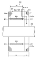
- FIG. 1 is a cross-sectional view of a motor according to Embodiment 1 of the present invention.
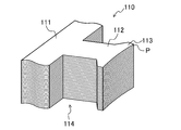
- FIG. 2 is a perspective view of the stator according to the first embodiment.
- FIG. 3 is a cross-sectional view of the tooth portion of the stator core according to the first embodiment when viewed from the inner peripheral side.
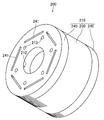
- FIG. 4 is a perspective view of the rotor according to the first embodiment.
- FIG. 5 is a cross-sectional view of the rotor according to the first embodiment.
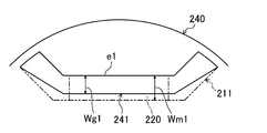
- FIG. 6 is a plan view of the first rotor core as seen from the axial direction.
- FIG. 7 is a diagram for explaining the relationship between the position and size of the magnet slot and the air gap.
- FIG. 8 is a perspective view illustrating an assembled state of the rotor according to the first embodiment.
- FIG. 9 is a diagram illustrating a magnetic path (reverse magnetic field magnetic path) when a reverse magnetic field acts.
- FIG. 10 is a cross-sectional view of a rotor according to Embodiment 2 of the present invention.
- FIG. 11 is a cross-sectional view of a rotor according to Embodiment 3 of the present invention.
- FIG. 12 is a cross-sectional view of a rotor according to Embodiment 4 of the present invention.
- FIG. 13 is a cross-sectional view of a rotor according to Embodiment 5 of the present invention.
- FIG. 14 is a plan view of a rotor according to the sixth embodiment.
- FIG. 10 is a cross-sectional view of a rotor according to Embodiment 2 of the present invention.
- FIG. 11 is a cross-sectional view of a rotor according to Embodiment 3 of the present invention.
- FIG. 12 is a cross-sectional view of a
- FIG. 15 is a cross-sectional view of a rotor according to Embodiment 6 of the present invention.
- FIG. 16 is a plan view showing Modification 1 of the air gap.
- FIG. 17 is a plan view showing Modification Example 2 of the air gap.
- FIG. 18 is a plan view showing a third modification of the air gap.
- FIG. 19 is a plan view showing Variation 4 of the gap.
- FIG. 20 is a plan view showing a fifth modification of the air gap.
- FIG. 1 is a cross-sectional view of a motor (10) according to Embodiment 1 of the present invention.
- This motor (10) is used for, for example, an electric compressor (not shown) of an air conditioner.
- the motor (10) includes a stator (100), a rotor (200), and a drive shaft (300), and is accommodated in the casing (20) of the electric compressor.
- the axial direction refers to the direction of the axis of the drive shaft (300)
- the radial direction refers to the direction orthogonal to the axis.
- the outer peripheral side means a side farther from the axis
- the inner peripheral side means a side closer to the axis.
- the stator (100) includes a cylindrical stator core (110) and a coil (120).
- the stator core (110) is a laminated core obtained by punching an electromagnetic steel plate (P) by press working to create a laminated plate and laminating a plurality of laminated plates in the axial direction.
- FIG. 2 is a perspective view of the stator (100) of the first embodiment. As shown in FIGS. 1 and 2, the stator core (110) includes one back yoke portion (111), a plurality of (in this example, nine) teeth portions (112), and a flange portion (113). . In FIG. 2, one tooth portion (112) is mainly drawn.
- Each tooth portion (112) is a rectangular parallelepiped portion extending in the radial direction in the stator core (110) as shown in FIGS.
- a space between the teeth portions (112) is a slot (114) in which the coil (120) is accommodated.
- the back yoke part (111) has an annular shape.
- the back yoke portion (111) connects the teeth portions (112) on the outer peripheral side of the teeth portion (112).
- the outer peripheral portion of the back yoke portion (111) is fixed to the inner surface of the casing (20).
- the brim portion (113) is a portion connected to the inner peripheral side of each tooth portion (112).
- the brim portion (113) has a larger width (length in the circumferential direction) than the teeth portion (112).
- the collar portion (113) has a cylindrical inner surface. The cylindrical surface is opposed to an outer peripheral surface (cylindrical surface) of a rotor core (210) described later with a predetermined distance (air gap (G)).
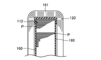
- FIG. 3 is a cross-sectional view of the tooth portion (112) when the stator core (110) of the present embodiment is viewed from the inner peripheral side.
- an insulator (161) is provided from both axial end surfaces of the tooth portion (112), and an insulating film (160) is provided between the coil (120) and the tooth portion (112). Is provided.
- the insulating film (160) is a polyethylene terephthalate film.
- FIG. 4 is a perspective view of the rotor (200) of the first embodiment.
- FIG. 5 is a cross-sectional view of the rotor (200) of the first embodiment.
- the rotor (200) includes a rotor core (210) (magnetic core), a plurality of permanent magnets (220), and two end plates (230), and has a cylindrical shape.
- the rotor (200) includes six permanent magnets (220).
- the end plate (230) is not shown.
- the rotor core (210) is a laminated core obtained by punching an electromagnetic steel plate (P) by press working to create a laminated plate and laminating a plurality of laminated plates in the axial direction.
- the rotor core (210) is divided into an odd number (three in this example) of rotor cores in contact with each other in the axial direction. More specifically, the rotor core (210) is divided into two first rotor cores (240) arranged oddly from the axial end of the rotor core (210) and second rotor cores (250) arranged evenly. And is divided into three in the axial direction (see FIG. 5). As shown in FIG. 5, in this example, the height (H1) (the size in the axial direction) of the first rotor core (240) is smaller than the height (H2) of the second rotor core (250).
- first and second rotor cores (240, 250) and the like will be described in detail.
- first rotor core (240) and the second rotor core (250) are also referred to as divided rotor cores (240, 250).
- the second rotor core (250) is formed with a plurality of magnet slots (211) into which the permanent magnets (220) are respectively attached.
- Each of the magnet slots (211) is disposed at a 60 ° pitch around the axis of the second rotor core (250).
- Each magnet slot (211) has a substantially U-shape when viewed in the axial direction, and penetrates the second rotor core (250) in the axial direction.
- each magnet slot (211) includes a magnet insertion part (211a) orthogonal to the radius of the rotor core (210), and 2 extending outward from the magnet insertion part (211a).
- the magnet insertion portion (211a) is rectangular in plan view in FIG. 1, and the permanent magnet (220) is inserted into the magnet insertion portion (211a).
- the permanent magnet (220) is configured such that the axial height (Hm) is smaller than the axial height (H2) of the second rotor core (250) (see FIG. 5).
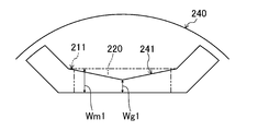
- FIG. 6 is a plan view of the first rotor core (240) viewed from the axial direction.
- the first rotor core (240) is provided with six gaps (241) penetrating in the axial direction. These gaps (241) are arranged to face the magnet slots (211) when the first rotor core (240) and the second rotor core (250) are overlapped.
- the magnet slots (211) corresponding to the respective gaps (241) are indicated by alternate long and short dash lines.
- FIG. 7 is a diagram for explaining the relationship between the position and size of the magnet slot (211) and the gap (241).
- the solid line indicates the shape of the gap (241)
- the alternate long and short dash line indicates the shape of the magnet slot (211).
- the gap (241) is rectangular in plan view in FIG.
- the width (Wg2) in the direction perpendicular to the radius in the gap (241) extends to the vicinity of the outer periphery of the first rotor core (240). By doing so, leakage magnetic flux generated between adjacent magnetic poles can be reduced.
- the air gap (241) has a smaller magnetic resistance than the magnet slot (211).
- the gap (241) has a radial width (Wg1) smaller than the radial width (Wm1) of the magnet insertion portion (211a).
- the radial direction position of the gap (241) is such that the long side (e1) on the outer peripheral side is on the inner peripheral side with respect to the long side (e2) of the magnet insertion part (211a).
- the width (Wg1) in the radial direction of the air gap (241) is formed to be larger than the air gap (G). This is because if the width (Wg1) is smaller than the air gap (G), the first rotor core (240) may cause a short circuit of magnetic flux.
- the end plate (230) has a disc shape and is formed of a nonmagnetic metal such as stainless steel.
- the end plate (230) and the first and second rotor cores (240, 250) are each formed with six bolt holes (213) that pass through in the axial direction and overlap each other when they are stacked.
- FIG. 8 is a perspective view illustrating an assembled state of the rotor (200) of the present embodiment.
- the permanent magnet (220) is attached to the magnet insertion part (211a).
- each permanent magnet (220) has its both ends in the axial direction offset inward from the axial end of the second rotor core (250).
- the permanent magnet (220) is fixed to the second rotor core (250) by, for example, bonding so as not to move in the magnet insertion portion (211a).
- the first and second rotor cores (240, 250) are arranged with the first rotor core (240) being odd-numbered from one end, and the second rotor core (250) being even-numbered from the one end.
- the second rotor core (250) is sandwiched between the first rotor core (240) from both axial ends.
- the first and third from the end of the rotor (200) are the first rotor core (240), and the second is the second rotor core (250).
- the positional relationship between the first rotor core (240) and the second rotor core (250) is matched so that each magnet slot (211) and the gap (241) of the first rotor core (240) overlap ( (See FIGS. 6 and 7).
- the first rotor core (240) and the second rotor core (250) are in contact with each other by overlapping the first rotor core (240) and the second rotor core (250), but the axial ends of the respective permanent magnets (220).
- the portion is offset inward from the axial end of the second rotor core (250), the permanent magnet (220) does not contact the first rotor core (240).
- end plates (230) are attached from the end of each first rotor core (240).
- the end plate (230) and the rotor core (210) are fixed by six bolts (270) (see FIG. 1) passed through the bolt holes (213).
- a shaft hole (212) is formed at the center of the first and second rotor cores (240, 250).
- a drive shaft (300) made of metal such as iron is shrink-fitted into the shaft hole (212).
- the drive shaft (300) is for driving a compression mechanism (not shown) in the electric compressor.
- FIG. 9 is a diagram illustrating a magnetic path (reverse magnetic field magnetic path) when a reverse magnetic field acts.
- a reverse magnetic field acts on the rotor (200) of the present embodiment
- a magnetic flux acts on the magnetic core portions (240a, 250a) (see FIG. 5) on the outer peripheral side of the permanent magnet (220) from the stator (100).
- This magnetic flux is directed to the magnetic core portion (250a) on the permanent magnet (220) side to some extent, but most of the magnetic flux is directed to the magnetic core portion (240a) of each first rotor core (240) as indicated by an arrow in FIG. Head to.
- the magnetic resistance of the air gap (241) of the first rotor core (240) is smaller than the magnetic resistance of the magnet slot (211). That is, in the motor (10) of this embodiment, the strength of the reverse magnetic field acting on the permanent magnet (220) is smaller than that of the conventional motor. Therefore, in this embodiment, it becomes possible to take measures against demagnetization of the permanent magnet (220) due to a reverse magnetic field.
- the motor (10) can generate reluctance torque by the first rotor core (240). That is, in this embodiment, the decrease in magnet torque can be compensated by the reluctance torque in the first rotor core (240).
- each magnet slot (211) is covered by the first rotor core (240). Therefore, it is possible to omit a cover or the like that prevents the permanent magnet (220) from coming off.
- FIG. 10 is a cross-sectional view of a rotor (200) according to Embodiment 2 of the present invention.
- the rotor (200) of the present embodiment includes one first rotor core (240) and one second rotor core (250). Also in this example, the height (H1) of the first rotor core (240) (the axial size) is smaller than the height (H2) of the second rotor core (250). Further, the first rotor core (240) and the second rotor core (250) are in contact with each other at the axial ends.
- the second rotor core (250) can easily insert the permanent magnet (220) into the magnet slot (211) from the axial end portion side not in contact with the first rotor core (240). Further, in the second rotor core (250), a cover or the like for preventing the permanent magnet (220) from coming off is not required on the axial end portion side in contact with the first rotor core (240).
- FIG. 11 is a cross-sectional view of a rotor (200) according to Embodiment 3 of the present invention.
- the rotor (200) of the present embodiment includes one first rotor core (240) and two second rotor cores (250).
- the first rotor core (240) is connected to the second rotor core (250 from both axial ends thereof. ).
- the height (H1) of the first rotor core (240) (the axial size) is smaller than the height (H2) of the second rotor core (250).
- the permanent magnet (220) can be inserted from both axial ends of the rotor (200). Therefore, assembly of the rotor (200) is facilitated.
- FIG. 12 is a cross-sectional view of a rotor (200) according to Embodiment 4 of the present invention.
- the rotor (200) includes two first rotor cores (240) and two second rotor cores (250), and the first and second rotor cores (240, 250) are alternately stacked.
- the height (H1) of the first rotor core (240) (the axial size) is smaller than the height (H2) of the second rotor core (250).
- FIG. 13 is a cross-sectional view of a rotor (200) according to Embodiment 5 of the present invention.
- the rotor (200) includes three first rotor cores (240) and two second rotor cores (250).
- the first rotor core (240) and the second rotor core (250) are alternately stacked.
- the height (H1) of the first rotor core (240) (the axial size) is smaller than the height (H2) of the second rotor core (250).
- H1 of the first rotor core (240) the axial size
- H2 height
- FIG. 14 is a plan view of the rotor (200) according to the sixth embodiment.
- FIG. 15 is a cross-sectional view of a rotor (200) according to Embodiment 6 of the present invention.
- FIG. 15 corresponds to the AA cross section of FIG.
- the rotor (200) of the present embodiment includes one first rotor core (240) and two second rotor cores (250), and the first rotor core (240) has both axial ends. And sandwiched between the second rotor cores (250). Also in this example, the height (H1) of the first rotor core (240) (the axial size) is smaller than the height (H2) of the second rotor core (250).
- the permanent magnet (220) is provided so as to constitute a multilayer for each pole. Specifically, three layers of permanent magnets (220) are provided on each pole.
- the permanent magnet (220) on the outermost peripheral side of the rotor (200) is provided only in the second rotor core (250). Further, the second and third permanent magnets (220) from the outer peripheral side of the rotor (200) are provided so as to penetrate the first and second rotor cores (240, 250).
- the second rotor core (250) is provided with a multilayer magnet slot (211) for each pole.
- the air gap (241) is provided only at a position corresponding to the outermost permanent magnet (220).
- each 1st rotor core (240) is the position of a 2nd rotor core (250) instead of a space
- a magnet slot (211) connected to the magnet slot (211) is formed.
- the demagnetization of the permanent magnet (220) corresponding to the air gap (241) Measures can be taken.
- the first rotor core (240) and the second rotor core (250) are the same as those in the first, second, fourth, and fourth embodiments. 5 can be arranged.
- a layer closer to the inner periphery than the first layer may have a gap (241) as in the first layer.
- the shape of the gap (241) is not limited to the above example. In each embodiment, for example, a gap (241) having a form exemplified below can be adopted.
- FIG. 16 is a plan view showing Modification 1 of the gap (241).
- the air gap (241) illustrated in FIG. 16 is a through-hole having a cross-sectional shape (projected shape in the axial direction) along the magnet slot (211) and narrower than the magnet slot (211). Also in this example, the end (241a) of the gap (241) extends to the vicinity of the outer periphery of the first rotor core (240).
- FIG. 17 is a plan view showing Modification 2 of the gap (241).
- the projected shape of the gap (241) in the axial direction is such that the radial width (Wg1) is the radial width (Wm1) of the magnet insertion portion (211a) at the portion overlapping the magnet insertion portion (211a).
- the long side (e1) on the outer peripheral side of the gap (241) is in a position overlapping the long side (e2) of the magnet insertion part (211a), but the long sides on the inner peripheral side overlap each other.
- the positional relationship between the air gap (241) and the magnet slot (211) may be determined.
- FIG. 18 is a plan view showing Modification 3 of the gap (241).
- the projected shape of the gap (241) in the axial direction is such that the width (Wg3) is narrower than the width of the barrier portion (211b) at the portion overlapping the barrier portion (211b), and the magnet insertion portion ( The portion overlapping 211a) is the same as or larger than the width (Wm1) of the magnet insertion portion (211a).
- FIG. 18 shows an example in which the width (Wg1) is larger than the width (Wm1).
- FIG. 19 is a plan view showing Modification 4 of the gap (241).
- the projected shape of the gap (241) in the axial direction is recessed near the center in the portion overlapping the magnet insertion portion (211a). Therefore, the radial width (Wg1) of the gap (241) is smaller than the radial width (Wm1) of the magnet slot (211).
- the portion that overlaps the barrier portion (211b) is generally shaped to overlap the barrier portion (211b).
- FIG. 20 is a plan view showing Modification 5 of the gap (241).
- the projected shape of the gap (241) in the axial direction is such that the inner peripheral line near both ends of the magnet insertion portion (211a) is recessed toward the outer peripheral side.
- the gap (241) has a width (Wg4) near the end of the magnet insertion portion (211a) smaller than a width near the center of the magnet slot (211).
- the inner circumferential side line of the gap (241) is dented toward the outer circumferential side, but the outer circumferential side line may be dented toward the inner circumferential side or dented from both the inner and outer sides. Good.
- the end of the air gap (241) in the direction perpendicular to the radius (the end (241a) or the like) extends as close as possible to the outer periphery of the first rotor core (240). This is because it is advantageous for reducing the leakage magnetic flux between adjacent poles.
- any of the air gaps (241) described in the above embodiments and modifications may be shifted within a range overlapping the projection surface in the axial direction of the permanent magnet (220). Further, as shown in FIG. 16 and the like, the air gap (241) does not have to be line symmetric with the radius as the axis of symmetry. You may combine the form of the space
- the number of divisions of the rotor core (210), that is, the number of the first and second rotor cores (240, 250) is an example.
- first and second rotor cores (240, 250) are not limited to laminated cores (electromagnetic steel plates).
- the first and second rotor cores (240, 250) can be made of a dust magnetic material.
- the rotor (200) is configured by combining the cores made of different kinds of magnetic materials, such as the first rotor core (240) made of powder magnetic material and the second rotor core (250) made of electromagnetic steel plate. May be.
- the end plate (230) may be omitted.
- the end plate (230) for preventing the magnet from coming off is made of a non-magnetic material or a magnetic material.
- the material cost increases, and in the case of a magnetic material, leakage of magnetic flux occurs.
- omitting the end plate (230) has the effect of reducing costs or improving torque.
- the present invention can be applied to a generator in addition to a motor.
- the present invention can also be applied to a rotating electric machine in which a coil is distributedly wound around a stator core.
- the present invention is useful as a rotor having a rotor core on which a magnet is mounted, and a rotating electric machine using the rotor.
Abstract
The purpose of the present invention is to provide a rotating electrical mechanism comprising a rotor having rotor cores onto which magnets have been mounted, wherein demagnetization of the magnets can be counteracted while a decline in the performance of the rotating electrical mechanism is suppressed. This rotor is provided with: first rotor cores (240) comprising a plurality of spaces (241) extending through in the axial direction; and a second core (250) in contact with the axial ends of the first rotor cores (240), the second core being provided with a plurality of magnet slots (211) at positions facing the spaces (241). The spaces (241) are formed with a lower magnetic resistance than the magnet slots (211). This configuration makes it possible to reduce the intensity of the reverse magnetic field acting on permanent magnets (220), and to cause a reluctance torque to be generated by the first rotor cores (240). Therefore, demagnetization of the magnets can be counteracted while a decline in performance can be suppressed in a rotating electrical mechanism comprising a rotor having rotor cores onto which magnets have been mounted.
Description
本発明は、磁石が装着されたロータコアを有したロータ、及びそれを用いた回転電気機械に関するものである。
The present invention relates to a rotor having a rotor core on which a magnet is mounted, and a rotary electric machine using the rotor.
磁石補助型のシンクロナスリラクタンスモータ(Synchronous Reluctance Motor,略してSynRM)や内部磁石埋込型モータ(Interior Permanent Magnet,略してIPMモータ)などの回転電気機械は、磁石が装着されたロータコアを有している。このような回転電気機械では、ロータコアの永久磁石に、何らかの原因で、大きな逆磁界がステータから作用し、上記永久磁石の磁力が低減する現象(減磁)が起こる場合がある。これに対しては、例えば磁石の厚みを増すことで対策が可能である。しかしながら、この対策はコストアップにつながるという問題がある。
Rotating electrical machines such as magnet-assisted synchronous reluctance motors (Synchronous Reluctance Motor, abbreviated SynRM) and interior magnet embedded motors (Interior Permanent Magnet, abbreviated IPM motors) have a rotor core on which magnets are mounted. ing. In such a rotating electric machine, a phenomenon in which a large reverse magnetic field acts on the permanent magnet of the rotor core from the stator for some reason and the magnetic force of the permanent magnet is reduced (demagnetization) may occur. For example, a countermeasure can be taken by increasing the thickness of the magnet. However, there is a problem that this measure leads to cost increase.
また、磁束の磁路を工夫することで、減磁の対策を図った例がある(例えば特許文献1を参照)。この例では、永久磁石の表面上に磁性部材が配置されている。そして、ロータ鉄心と磁気的に結合し且つ上記磁性部材の端部と適宜の空隙をおいて、磁性材製のエンドリングが設けられている。
Also, there is an example of demagnetizing measures by devising the magnetic path of the magnetic flux (see, for example, Patent Document 1). In this example, a magnetic member is disposed on the surface of the permanent magnet. An end ring made of a magnetic material is provided that is magnetically coupled to the rotor iron core and has an appropriate gap from the end of the magnetic member.
しかしながら、特許文献1の例では、ロータ本体とエンドリングの間には空隙が設けられているので、モータ全体としてのサイズを従来通りに維持しようとすると、ロータ鉄心を配置できるスペースが小さくなる。すなわち、ロータ鉄心が小さくなり、モータとしての性能低下が懸念される。逆に、ロータ鉄心のサイズを従来通りに確保すれば、モータ全体としてのサイズが大きくなってしまい、コストアップにつながる可能性がある。
However, in the example of Patent Document 1, a gap is provided between the rotor body and the end ring. Therefore, if the size of the entire motor is maintained as usual, the space in which the rotor iron core can be disposed is reduced. That is, the rotor core becomes small, and there is a concern that the performance as a motor may be reduced. On the other hand, if the size of the rotor core is ensured as before, the size of the entire motor becomes large, which may lead to an increase in cost.
本発明は上記の問題に着目してなされたものであり、磁石が装着されたロータコアを有したロータを備えた回転電気機械において、回転電気機械としての性能低下を抑制しつつ、磁石の減磁の対策を図ることを目的としている。
The present invention has been made paying attention to the above problems, and in a rotating electric machine having a rotor having a rotor core on which a magnet is mounted, the magnet demagnetization is performed while suppressing a decrease in performance as the rotating electric machine. The purpose is to take measures.
上記の課題を解決するため、第1の発明は、
複数の永久磁石(220)を有したロータにおいて、
軸方向に貫通する複数の空隙(241)を有した第1ロータコア(240)と、
上記第1ロータコア(240)の軸方向端部に接するとともに、上記空隙(241)に対応して複数の磁石用スロット(211)が形成された第2ロータコア(250)とを備え、
上記空隙(241)は、上記磁石用スロット(211)よりも磁気抵抗が小さいことを特徴とする。 In order to solve the above problems, the first invention is
In a rotor having a plurality of permanent magnets (220),
A first rotor core (240) having a plurality of gaps (241) penetrating in the axial direction;
A second rotor core (250) in contact with the axial end of the first rotor core (240) and having a plurality of magnet slots (211) corresponding to the gap (241);
The air gap (241) has a smaller magnetic resistance than the magnet slot (211).
この構成では、例えば、ロータ(200)に逆磁界が作用すると、この磁束は、ある程度は、磁石用スロット(211)内の永久磁石(220)側に向かうが、その多くが第1ロータコア(240)側へと向かう。これは、空隙(241)の磁気抵抗の方が、磁石用スロット(211)の磁気抵抗よりも小さいからである。すなわち、本発明のモータでは、従来のモータと比べ、永久磁石(220)に作用する磁界強度を小さくできる。
In this configuration, for example, when a reverse magnetic field acts on the rotor (200), the magnetic flux is directed to the permanent magnet (220) side in the magnet slot (211) to some extent, but most of the magnetic flux is directed to the first rotor core (240). ) Go to the side. This is because the magnetic resistance of the air gap (241) is smaller than that of the magnet slot (211). That is, in the motor of the present invention, the magnetic field strength acting on the permanent magnet (220) can be reduced as compared with the conventional motor.
また、第1ロータコア(240)と第2ロータコア(250)とは接しているので、第1ロータコア(240)にはステータ(100)(後述)からの磁界が効率的に作用する。そのため、第1ロータコア(240)によってリラクタンストルクを発生させることができる。
Further, since the first rotor core (240) and the second rotor core (250) are in contact with each other, the magnetic field from the stator (100) (described later) acts efficiently on the first rotor core (240). Therefore, reluctance torque can be generated by the first rotor core (240).
また、第2の発明は、
第1の発明のロータにおいて、
上記空隙(241)の半径方向の幅(Wg1)は、上記磁石用スロット(211)の半径方向の幅(Wm1)よりも小さいことを特徴とする。 In addition, the second invention,
In the rotor of the first invention,
The radial width (Wg1) of the air gap (241) is smaller than the radial width (Wm1) of the magnet slot (211).
第1の発明のロータにおいて、
上記空隙(241)の半径方向の幅(Wg1)は、上記磁石用スロット(211)の半径方向の幅(Wm1)よりも小さいことを特徴とする。 In addition, the second invention,
In the rotor of the first invention,
The radial width (Wg1) of the air gap (241) is smaller than the radial width (Wm1) of the magnet slot (211).
この構成では、空隙(241)の半径方向の幅(Wg1)の設定によって、空隙(241)の磁気抵抗が定まる。
In this configuration, the magnetic resistance of the air gap (241) is determined by setting the radial width (Wg1) of the air gap (241).
また、第3の発明は、
第1又は第2の発明のロータにおいて、
上記第1ロータコア(240)は、上記第2ロータコア(250)よりも軸方向の大きさが小さいことを特徴とする。 In addition, the third invention,
In the rotor of the first or second invention,
The first rotor core (240) has a smaller axial size than the second rotor core (250).
第1又は第2の発明のロータにおいて、
上記第1ロータコア(240)は、上記第2ロータコア(250)よりも軸方向の大きさが小さいことを特徴とする。 In addition, the third invention,
In the rotor of the first or second invention,
The first rotor core (240) has a smaller axial size than the second rotor core (250).
この構成では、上記リラクタンストルクよりもマグネットトルクの方が支配的になる。
In this configuration, the magnet torque is more dominant than the reluctance torque.
また、第4の発明は、
第1から第3の発明の何れかのロータにおいて、
上記第2ロータコア(250)は、軸方向両端から上記第1ロータコア(240)に挟み込まれていることを特徴とする。 In addition, the fourth invention is
In any one of the rotors of the first to third inventions,
The second rotor core (250) is sandwiched between the first rotor core (240) from both axial ends.
第1から第3の発明の何れかのロータにおいて、
上記第2ロータコア(250)は、軸方向両端から上記第1ロータコア(240)に挟み込まれていることを特徴とする。 In addition, the fourth invention is
In any one of the rotors of the first to third inventions,
The second rotor core (250) is sandwiched between the first rotor core (240) from both axial ends.
この構成では、ロータ(200)に逆磁界が作用すると、この磁束の多くがロータ(200)の軸方向両端に向かう。また、それぞれの磁石用スロット(211)は、第1ロータコア(240)によってカバーされる。
In this configuration, when a reverse magnetic field acts on the rotor (200), most of the magnetic flux is directed to both ends of the rotor (200) in the axial direction. Each magnet slot (211) is covered by the first rotor core (240).
また、第5の発明は、
第1から第3の発明の何れかのロータにおいて、
上記第1ロータコア(240)は、軸方向両端から上記第2ロータコア(250)に挟み込まれていることを特徴とする。 In addition, the fifth invention,
In any one of the rotors of the first to third inventions,
The first rotor core (240) is sandwiched between the second rotor core (250) from both axial ends.
第1から第3の発明の何れかのロータにおいて、
上記第1ロータコア(240)は、軸方向両端から上記第2ロータコア(250)に挟み込まれていることを特徴とする。 In addition, the fifth invention,
In any one of the rotors of the first to third inventions,
The first rotor core (240) is sandwiched between the second rotor core (250) from both axial ends.
この構成では、ロータ(200)に逆磁界が作用すると、この磁束の多くがロータ(200)の軸方向中心部に向かう。
In this configuration, when a reverse magnetic field acts on the rotor (200), most of this magnetic flux is directed toward the axial center of the rotor (200).
また、第6の発明は、
第1から第5の発明の何れかのロータ(200)と、
コイル(120)が巻回されたステータコア(110)を有したステータ(100)とを備えたことを特徴とする。 In addition, the sixth invention,
Any one of the rotors (200) of the first to fifth inventions;
And a stator (100) having a stator core (110) around which a coil (120) is wound.
第1から第5の発明の何れかのロータ(200)と、
コイル(120)が巻回されたステータコア(110)を有したステータ(100)とを備えたことを特徴とする。 In addition, the sixth invention,
Any one of the rotors (200) of the first to fifth inventions;
And a stator (100) having a stator core (110) around which a coil (120) is wound.
また、第7の発明は、
第6の発明の回転電気機械において、
上記空隙(241)の半径方向の幅(Wg1)は、上記ロータ(200)と上記ステータ(100)と間のエアギャップ(G)よりも大きいことを特徴とする。 In addition, the seventh invention,
In the rotary electric machine of the sixth invention,
A radial width (Wg1) of the air gap (241) is larger than an air gap (G) between the rotor (200) and the stator (100).
第6の発明の回転電気機械において、
上記空隙(241)の半径方向の幅(Wg1)は、上記ロータ(200)と上記ステータ(100)と間のエアギャップ(G)よりも大きいことを特徴とする。 In addition, the seventh invention,
In the rotary electric machine of the sixth invention,
A radial width (Wg1) of the air gap (241) is larger than an air gap (G) between the rotor (200) and the stator (100).
この構成では、幅(Wg1)がエアギャップ(G)よりも大きいので、第1ロータコア(240)による磁束の短絡が防止される。
In this configuration, since the width (Wg1) is larger than the air gap (G), a short circuit of magnetic flux by the first rotor core (240) is prevented.
第1の発明によれば、永久磁石(220)に作用する逆磁界の強度を小さくでき、且つ第1ロータコア(240)によってリラクタンストルクを発生させることができる。そのため、磁石が装着されたロータコアを有したロータを備えた回転電気機械において、回転電気機械としての性能低下を抑制しつつ、減磁の対策を図ることが可能になる。
According to the first invention, the strength of the reverse magnetic field acting on the permanent magnet (220) can be reduced, and reluctance torque can be generated by the first rotor core (240). Therefore, in a rotating electric machine including a rotor having a rotor core on which a magnet is mounted, it is possible to take measures against demagnetization while suppressing a decrease in performance as the rotating electric machine.
また、第2の発明によれば、空隙(241)の半径方向の幅(Wg1)で磁気抵抗を設定できるので、上記磁気抵抗の設定が容易である。
Further, according to the second invention, since the magnetic resistance can be set by the radial width (Wg1) of the air gap (241), the setting of the magnetic resistance is easy.
また、第4の発明によれば、ロータ(200)に作用した逆磁界の多くが軸方向両端に向かうので、永久磁石(220)の両端における減磁の対策を図ることが可能になる。また、各磁石用スロット(211)が第1ロータコア(240)によってカバーされるので、永久磁石(220)の抜けを防止するカバー等を省略することが可能になる。
Further, according to the fourth aspect of the invention, since most of the reverse magnetic field that has acted on the rotor (200) is directed to both ends in the axial direction, it is possible to take measures against demagnetization at both ends of the permanent magnet (220). Further, since each magnet slot (211) is covered by the first rotor core (240), a cover for preventing the permanent magnet (220) from coming off can be omitted.
また、第5の発明によれば、ロータ(200)に作用した逆磁界の多くが軸方向中心部に向かうので、永久磁石(220)の軸方向中心部における減磁の対策を図ることが可能になる。また、この構成では、ロータ(200)の軸方向両端から永久磁石(220)を挿入することができる。そのため、ロータ(200)の組み立てが容易になる。
According to the fifth aspect of the invention, since most of the reverse magnetic field that has acted on the rotor (200) is directed to the axial center, it is possible to take measures against demagnetization at the axial center of the permanent magnet (220). become. In this configuration, the permanent magnet (220) can be inserted from both axial ends of the rotor (200). Therefore, assembly of the rotor (200) is facilitated.
また、第7の発明によれば、上記磁束の短絡が防止されるので、回転電気機械の安定的な運転ができる。
Further, according to the seventh invention, since the magnetic flux is prevented from being short-circuited, the rotating electric machine can be stably operated.
以下、本発明の実施形態について図面を参照しながら説明する。なお、以下の実施形態は、本質的に好ましい例示であって、本発明、その適用物、あるいはその用途の範囲を制限することを意図するものではない。
Hereinafter, embodiments of the present invention will be described with reference to the drawings. The following embodiments are essentially preferable examples, and are not intended to limit the scope of the present invention, its application, or its use.
《発明の実施形態1》
図1は、本発明の実施形態1に係るモータ(10)の横断面図である。このモータ(10)は、例えば空気調和機の電動圧縮機(図示は省略)に用いる。 Embodiment 1 of the Invention
FIG. 1 is a cross-sectional view of a motor (10) according to Embodiment 1 of the present invention. This motor (10) is used for, for example, an electric compressor (not shown) of an air conditioner.
〈モータ(10)の構成〉
モータ(10)は、図1に示すように、ステータ(100)、ロータ(200)、及び駆動軸(300)を備え、上記電動圧縮機のケーシング(20)に収容されている。なお、以下の説明において、軸方向とは駆動軸(300)の軸心の方向をいい、径方向とは上記軸心と直交する方向をいう。また、外周側とは上記軸心からより遠い側をいい、内周側とは上記軸心により近い側をいう。 <Configuration of motor (10)>
As shown in FIG. 1, the motor (10) includes a stator (100), a rotor (200), and a drive shaft (300), and is accommodated in the casing (20) of the electric compressor. In the following description, the axial direction refers to the direction of the axis of the drive shaft (300), and the radial direction refers to the direction orthogonal to the axis. Further, the outer peripheral side means a side farther from the axis, and the inner peripheral side means a side closer to the axis.
〈ステータ(100)〉
ステータ(100)は、図1に示すように、円筒状のステータコア(110)と、コイル(120)を備えている。 <Stator (100)>
As shown in FIG. 1, the stator (100) includes a cylindrical stator core (110) and a coil (120).
ステータ(100)は、図1に示すように、円筒状のステータコア(110)と、コイル(120)を備えている。 <Stator (100)>
As shown in FIG. 1, the stator (100) includes a cylindrical stator core (110) and a coil (120).
ステータコア(110)は、電磁鋼板(P)をプレス加工によって打ち抜いて積層板を作成し、複数の積層板を軸方向に積層した積層コアである。図2は、実施形態1のステータ(100)の斜視図である。ステータコア(110)は、図1,2に示すように、1つのバックヨーク部(111)、それぞれ複数(この例では9つ)のティース部(112)、及びツバ部(113)を備えている。なお、図2には、1つのティース部(112)を主に描いてある。
The stator core (110) is a laminated core obtained by punching an electromagnetic steel plate (P) by press working to create a laminated plate and laminating a plurality of laminated plates in the axial direction. FIG. 2 is a perspective view of the stator (100) of the first embodiment. As shown in FIGS. 1 and 2, the stator core (110) includes one back yoke portion (111), a plurality of (in this example, nine) teeth portions (112), and a flange portion (113). . In FIG. 2, one tooth portion (112) is mainly drawn.
それぞれのティース部(112)は、図1,2に示すように、ステータコア(110)において径方向に伸びる直方体状の部分である。各ティース部(112)の間の空間が、コイル(120)が収容されるスロット(114)である。
Each tooth portion (112) is a rectangular parallelepiped portion extending in the radial direction in the stator core (110) as shown in FIGS. A space between the teeth portions (112) is a slot (114) in which the coil (120) is accommodated.
バックヨーク部(111)は、円環状をしている。バックヨーク部(111)は、各ティース部(112)を該ティース部(112)の外周側で連結している。ステータコア(110)は、バックヨーク部(111)の外周部がケーシング(20)の内面に固定されている。
The back yoke part (111) has an annular shape. The back yoke portion (111) connects the teeth portions (112) on the outer peripheral side of the teeth portion (112). In the stator core (110), the outer peripheral portion of the back yoke portion (111) is fixed to the inner surface of the casing (20).
ツバ部(113)は、それぞれのティース部(112)の内周側に連なる部分である。ツバ部(113)は、ティース部(112)よりも幅(周方向の長さ)が大きく構成されている。ツバ部(113)は、内周側の面が円筒面である。その円筒面は、後述のロータコア(210)の外周面(円筒面)と所定の距離(エアギャップ(G))をもって対向している。
The brim portion (113) is a portion connected to the inner peripheral side of each tooth portion (112). The brim portion (113) has a larger width (length in the circumferential direction) than the teeth portion (112). The collar portion (113) has a cylindrical inner surface. The cylindrical surface is opposed to an outer peripheral surface (cylindrical surface) of a rotor core (210) described later with a predetermined distance (air gap (G)).
ティース部(112)には、いわゆる集中巻方式で、コイル(120)が巻回されている。すなわち、1つのティース部(112)ごとにコイル(120)が巻回され、巻回されたコイル(120)はスロット(114)内に収容されている。図3は、本実施形態のステータコア(110)を内周側から見た、ティース部(112)の断面図である。同図に示すように、ティース部(112)の軸方向の両端面側からインシュレータ(161)が設けられるとともに、コイル(120)とティース部(112)の間には、絶縁フィルム(160)が設けられている。この例では、絶縁フィルム(160)は、ポリエチレンテレフタレートのフィルムである。
The coil (120) is wound around the teeth portion (112) by a so-called concentrated winding method. That is, the coil (120) is wound for each tooth portion (112), and the wound coil (120) is accommodated in the slot (114). FIG. 3 is a cross-sectional view of the tooth portion (112) when the stator core (110) of the present embodiment is viewed from the inner peripheral side. As shown in the figure, an insulator (161) is provided from both axial end surfaces of the tooth portion (112), and an insulating film (160) is provided between the coil (120) and the tooth portion (112). Is provided. In this example, the insulating film (160) is a polyethylene terephthalate film.
〈ロータ(200)〉
図4は、実施形態1のロータ(200)の斜視図である。また、図5は、実施形態1のロータ(200)の断面図である。ロータ(200)は、ロータコア(210)(磁心)、複数の永久磁石(220)、及び2つの端板(230)を備え、円筒状の形態である。この例では、ロータ(200)は、6つの永久磁石(220)を備えている。なお、図4では端板(230)の図示を省略してある。 <Rotor (200)>
FIG. 4 is a perspective view of the rotor (200) of the first embodiment. FIG. 5 is a cross-sectional view of the rotor (200) of the first embodiment. The rotor (200) includes a rotor core (210) (magnetic core), a plurality of permanent magnets (220), and two end plates (230), and has a cylindrical shape. In this example, the rotor (200) includes six permanent magnets (220). In FIG. 4, the end plate (230) is not shown.
ロータコア(210)は、電磁鋼板(P)をプレス加工によって打ち抜いて積層板を作成し、複数の積層板を軸方向に積層した積層コアである。ロータコア(210)は、後に詳述するように、上記軸方向に、互いに接する奇数個(この例では3つ)のロータコアに分割されている。より詳しくは、ロータコア(210)は、ロータコア(210)の軸方向の端から奇数番目に配置された2つの第1ロータコア(240)と、偶数番目に配置された第2ロータコア(250)とに、軸方向に3分割されている(図5を参照)。図5に示すように、この例では、第1ロータコア(240)の高さ(H1)(上記軸方向の大きさ)は、第2ロータコア(250)の高さ(H2)よりも小さい。
The rotor core (210) is a laminated core obtained by punching an electromagnetic steel plate (P) by press working to create a laminated plate and laminating a plurality of laminated plates in the axial direction. As will be described in detail later, the rotor core (210) is divided into an odd number (three in this example) of rotor cores in contact with each other in the axial direction. More specifically, the rotor core (210) is divided into two first rotor cores (240) arranged oddly from the axial end of the rotor core (210) and second rotor cores (250) arranged evenly. And is divided into three in the axial direction (see FIG. 5). As shown in FIG. 5, in this example, the height (H1) (the size in the axial direction) of the first rotor core (240) is smaller than the height (H2) of the second rotor core (250).
以下では、第1及び第2ロータコア(240,250)等の構成について詳述する。なお、以下では、第1ロータコア(240)や第2ロータコア(250)を分割ロータコア(240,250)とも呼ぶ。
Hereinafter, the configuration of the first and second rotor cores (240, 250) and the like will be described in detail. Hereinafter, the first rotor core (240) and the second rotor core (250) are also referred to as divided rotor cores (240, 250).
〈第2ロータコア(250)〉
図4等に示すように、第2ロータコア(250)には、永久磁石(220)をそれぞれ装着する、複数の磁石用スロット(211)が形成されている。それぞれの磁石用スロット(211)は、第2ロータコア(250)の軸心回りに60°ピッチで配置されている。それぞれの磁石用スロット(211)は、軸方向から見て概ねU字状の形状を有し、第2ロータコア(250)を軸方向に貫通している。詳しくは、図4に示すように、それぞれの磁石用スロット(211)は、ロータコア(210)の半径と直交する磁石挿入部(211a)と、該磁石挿入部(211a)から外周側に延びる2つのバリア部(211b)とで構成されている。磁石挿入部(211a)は、図1における平面視が長方形であり、該磁石挿入部(211a)に永久磁石(220)が挿入される。永久磁石(220)は、軸方向の高さ(Hm)が第2ロータコア(250)の軸方向の高さ(H2)よりも小さく構成されている(図5参照)。 <Second rotor core (250)>
As shown in FIG. 4 and the like, the second rotor core (250) is formed with a plurality of magnet slots (211) into which the permanent magnets (220) are respectively attached. Each of the magnet slots (211) is disposed at a 60 ° pitch around the axis of the second rotor core (250). Each magnet slot (211) has a substantially U-shape when viewed in the axial direction, and penetrates the second rotor core (250) in the axial direction. Specifically, as shown in FIG. 4, each magnet slot (211) includes a magnet insertion part (211a) orthogonal to the radius of the rotor core (210), and 2 extending outward from the magnet insertion part (211a). It consists of two barrier parts (211b). The magnet insertion portion (211a) is rectangular in plan view in FIG. 1, and the permanent magnet (220) is inserted into the magnet insertion portion (211a). The permanent magnet (220) is configured such that the axial height (Hm) is smaller than the axial height (H2) of the second rotor core (250) (see FIG. 5).
〈第1ロータコア(240)〉
図6は、第1ロータコア(240)を軸方向から見た平面図である。図6に示すように、第1ロータコア(240)は、軸方向に貫通する6つの空隙(241)が設けられている。これらの空隙(241)は、第1ロータコア(240)と第2ロータコア(250)とを重ねると、磁石用スロット(211)と対向するように配置されている。なお、図6では、それぞれの空隙(241)が対応する磁石用スロット(211)を、一点鎖線で表示してある。 <First rotor core (240)>
FIG. 6 is a plan view of the first rotor core (240) viewed from the axial direction. As shown in FIG. 6, the first rotor core (240) is provided with six gaps (241) penetrating in the axial direction. These gaps (241) are arranged to face the magnet slots (211) when the first rotor core (240) and the second rotor core (250) are overlapped. In FIG. 6, the magnet slots (211) corresponding to the respective gaps (241) are indicated by alternate long and short dash lines.
図7は、磁石用スロット(211)と空隙(241)の位置及び大きさの関係を説明する図である。図7において、実線が空隙(241)の形状を示し、一点鎖線が磁石用スロット(211)の形状を示している。この例では、空隙(241)は、図7における平面視が長方形である。空隙(241)における、半径と直交する方向の幅(Wg2)は、第1ロータコア(240)の外周近傍まで延びている。こうすることで、隣接する磁極との間に生ずる漏れ磁束を低減できる。
FIG. 7 is a diagram for explaining the relationship between the position and size of the magnet slot (211) and the gap (241). In FIG. 7, the solid line indicates the shape of the gap (241), and the alternate long and short dash line indicates the shape of the magnet slot (211). In this example, the gap (241) is rectangular in plan view in FIG. The width (Wg2) in the direction perpendicular to the radius in the gap (241) extends to the vicinity of the outer periphery of the first rotor core (240). By doing so, leakage magnetic flux generated between adjacent magnetic poles can be reduced.
空隙(241)は、磁石用スロット(211)よりも磁気抵抗が小さく形成されている。この例では、空隙(241)は、半径方向の幅(Wg1)が磁石挿入部(211a)の半径方向の幅(Wm1)よりも小さい。これにより、半径方向においては、空隙(241)は、磁石用スロット(211)よりも磁気抵抗が小さくなる。空隙(241)の半径方向の位置は、外周側の長辺(e1)が、磁石挿入部(211a)の長辺(e2)よりも内周側にある。また、空隙(241)の半径方向の幅(Wg1)は、エアギャップ(G)以上の大きさに形成されている。これは、もし幅(Wg1)がエアギャップ(G)よりも小さいと、第1ロータコア(240)によって磁束の短絡が起こるおそれがあるからである。
The air gap (241) has a smaller magnetic resistance than the magnet slot (211). In this example, the gap (241) has a radial width (Wg1) smaller than the radial width (Wm1) of the magnet insertion portion (211a). Thus, in the radial direction, the air gap (241) has a smaller magnetic resistance than the magnet slot (211). The radial direction position of the gap (241) is such that the long side (e1) on the outer peripheral side is on the inner peripheral side with respect to the long side (e2) of the magnet insertion part (211a). Further, the width (Wg1) in the radial direction of the air gap (241) is formed to be larger than the air gap (G). This is because if the width (Wg1) is smaller than the air gap (G), the first rotor core (240) may cause a short circuit of magnetic flux.
〈端板(230)〉
端板(230)は、円板状の形態を有し、例えばステンレスなどの非磁性金属で形成されている。端板(230)、第1及び第2ロータコア(240,250)には、軸方向に貫通し、これらを重ねた状態で互いに重なるボルト穴(213)がそれぞれ6つ形成されている。 <End plate (230)>
The end plate (230) has a disc shape and is formed of a nonmagnetic metal such as stainless steel. The end plate (230) and the first and second rotor cores (240, 250) are each formed with six bolt holes (213) that pass through in the axial direction and overlap each other when they are stacked.
〈ロータ(200)の組み立て状態〉
図8は、本実施形態のロータ(200)の組み立て状態を説明する斜視図である。第2ロータコア(250)には、磁石挿入部(211a)に永久磁石(220)を装着する。この場合、それぞれの永久磁石(220)は、図5に示すように、軸方向の両端部を第2ロータコア(250)の軸方向端から内側にオフセットさせておく。なお、永久磁石(220)は、磁石挿入部(211a)内で移動しないように、例えば接着するなどして第2ロータコア(250)に固定しておく。 <Assembly state of rotor (200)>
FIG. 8 is a perspective view illustrating an assembled state of the rotor (200) of the present embodiment. In the second rotor core (250), the permanent magnet (220) is attached to the magnet insertion part (211a). In this case, as shown in FIG. 5, each permanent magnet (220) has its both ends in the axial direction offset inward from the axial end of the second rotor core (250). The permanent magnet (220) is fixed to the second rotor core (250) by, for example, bonding so as not to move in the magnet insertion portion (211a).
ロータ(200)では、第1及び第2ロータコア(240,250)は、一端から奇数番目に第1ロータコア(240)を配置し、上記一端から偶数番目に第2ロータコア(250)を配置する。この例では、図8に示すように、第2ロータコア(250)を軸方向両端から、第1ロータコア(240)で挟みこむ。これにより、ロータ(200)の端から1番目と3番目が第1ロータコア(240)、2番目が第2ロータコア(250)となる。このとき、各磁石用スロット(211)と、第1ロータコア(240)の空隙(241)とが重なるように、第1ロータコア(240)と第2ロータコア(250)の位置関係を合わせておく(図6,7参照)。なお、第1ロータコア(240)と第2ロータコア(250)を重ねることで、第1ロータコア(240)と第2ロータコア(250)とは互いに接するが、それぞれの永久磁石(220)の軸方向端部は、既述の通り、第2ロータコア(250)の軸方向端から内側にオフセットしているので、永久磁石(220)は第1ロータコア(240)に接触しない。
In the rotor (200), the first and second rotor cores (240, 250) are arranged with the first rotor core (240) being odd-numbered from one end, and the second rotor core (250) being even-numbered from the one end. In this example, as shown in FIG. 8, the second rotor core (250) is sandwiched between the first rotor core (240) from both axial ends. Thus, the first and third from the end of the rotor (200) are the first rotor core (240), and the second is the second rotor core (250). At this time, the positional relationship between the first rotor core (240) and the second rotor core (250) is matched so that each magnet slot (211) and the gap (241) of the first rotor core (240) overlap ( (See FIGS. 6 and 7). The first rotor core (240) and the second rotor core (250) are in contact with each other by overlapping the first rotor core (240) and the second rotor core (250), but the axial ends of the respective permanent magnets (220). As described above, since the portion is offset inward from the axial end of the second rotor core (250), the permanent magnet (220) does not contact the first rotor core (240).
それぞれの第1ロータコア(240)の端からは、図8に示すように、端板(230)を取り付ける。端板(230)とロータコア(210)は、ボルト穴(213)に通した6つのボルト(270)(図1参照)で固定する。
As shown in FIG. 8, end plates (230) are attached from the end of each first rotor core (240). The end plate (230) and the rotor core (210) are fixed by six bolts (270) (see FIG. 1) passed through the bolt holes (213).
なお、第1及び第2ロータコア(240,250)の中心には、軸穴(212)を形成してある。この軸穴(212)には、鉄などの金属で構成された駆動軸(300)を焼き嵌めする。駆動軸(300)は、上記電動圧縮機内の圧縮機構(図示は省略)を駆動するためのものである。
A shaft hole (212) is formed at the center of the first and second rotor cores (240, 250). A drive shaft (300) made of metal such as iron is shrink-fitted into the shaft hole (212). The drive shaft (300) is for driving a compression mechanism (not shown) in the electric compressor.
《逆磁界作用時の磁路》
図9は、逆磁界が作用した際の磁路(逆磁界磁路)を説明する図である。例えば、本実施形態のロータ(200)に逆磁界が作用し、ステータ(100)から永久磁石(220)の外周側にある磁心部(240a,250a)(図5参照)に磁束が作用したとする。この磁束は、ある程度は永久磁石(220)側の磁心部(250a)に向かうが、その多くが、図9に矢印で示すように、それぞれの第1ロータコア(240)の磁心部(240a)へと向かう。これは、第1ロータコア(240)の空隙(241)の磁気抵抗の方が、磁石用スロット(211)の磁気抵抗よりも小さいからである。すなわち、本実施形態のモータ(10)では、従来のモータと比べ、永久磁石(220)に作用する逆磁界強度が小さい。したがって、本実施形態では、逆磁界による永久磁石(220)の減磁を対策することが可能になる。 <Magnetic path during reverse magnetic field action>
FIG. 9 is a diagram illustrating a magnetic path (reverse magnetic field magnetic path) when a reverse magnetic field acts. For example, a reverse magnetic field acts on the rotor (200) of the present embodiment, and a magnetic flux acts on the magnetic core portions (240a, 250a) (see FIG. 5) on the outer peripheral side of the permanent magnet (220) from the stator (100). To do. This magnetic flux is directed to the magnetic core portion (250a) on the permanent magnet (220) side to some extent, but most of the magnetic flux is directed to the magnetic core portion (240a) of each first rotor core (240) as indicated by an arrow in FIG. Head to. This is because the magnetic resistance of the air gap (241) of the first rotor core (240) is smaller than the magnetic resistance of the magnet slot (211). That is, in the motor (10) of this embodiment, the strength of the reverse magnetic field acting on the permanent magnet (220) is smaller than that of the conventional motor. Therefore, in this embodiment, it becomes possible to take measures against demagnetization of the permanent magnet (220) due to a reverse magnetic field.
本実施形態では、モータ(10)のサイズを従来と同等にしようとすれば、第1ロータコア(240)を設けた分だけ永久磁石(220)の軸方向長さ(Hm)が短くなるので、マグネットトルクの低下が考えられる。しかしながら、第1ロータコア(240)は、第2ロータコア(250)と接しているので、第1ロータコア(240)にはステータ(100)からの磁界が効率的に作用する。そのため、モータ(10)は、第1ロータコア(240)によってリラクタンストルクを発生させることができる。すなわち、本実施形態では、第1ロータコア(240)におけるリラクタンストルクによって、マグネットトルクの低下を補うことができるのである。
In the present embodiment, if the size of the motor (10) is made equal to the conventional size, the axial length (Hm) of the permanent magnet (220) is shortened by the amount of the first rotor core (240) provided. A decrease in magnet torque is considered. However, since the first rotor core (240) is in contact with the second rotor core (250), the magnetic field from the stator (100) acts efficiently on the first rotor core (240). Therefore, the motor (10) can generate reluctance torque by the first rotor core (240). That is, in this embodiment, the decrease in magnet torque can be compensated by the reluctance torque in the first rotor core (240).
《本実施形態における効果》
したがって、本実施形態によれば、磁石が装着されたロータコアを有したロータを備えたモータにおいて、モータとしての性能低下を抑制しつつ、減磁の対策を図ることが可能になる。 << Effect in this embodiment >>
Therefore, according to the present embodiment, in a motor including a rotor having a rotor core on which a magnet is mounted, it is possible to take measures against demagnetization while suppressing a decrease in performance as a motor.
また、それぞれの磁石用スロット(211)は、第1ロータコア(240)によってカバーされる。そのため、永久磁石(220)の抜けを防止するカバー等を省略することが可能になる。
Also, each magnet slot (211) is covered by the first rotor core (240). Therefore, it is possible to omit a cover or the like that prevents the permanent magnet (220) from coming off.
《発明の実施形態2》
図10は、本発明の実施形態2に係るロータ(200)の断面図である。本実施形態のロータ(200)は、第1ロータコア(240)と第2ロータコア(250)とをひとつずつ備えている。この例でも第1ロータコア(240)の高さ(H1)(上記軸方向の大きさ)は、第2ロータコア(250)の高さ(H2)よりも小さい。また、第1ロータコア(240)と第2ロータコア(250)とは、互いに軸方向端部で接している。 << Embodiment 2 of the Invention >>
FIG. 10 is a cross-sectional view of a rotor (200) according to Embodiment 2 of the present invention. The rotor (200) of the present embodiment includes one first rotor core (240) and one second rotor core (250). Also in this example, the height (H1) of the first rotor core (240) (the axial size) is smaller than the height (H2) of the second rotor core (250). Further, the first rotor core (240) and the second rotor core (250) are in contact with each other at the axial ends.
このような構成とすることで、本実施形態においても、ロータ(200)に逆磁界が作用しても、その磁束の多くが、第1ロータコア(240)側の磁心部(240a)へと向かう。そのため、本実施形態では、それぞれの永久磁石(220)の第1ロータコア(240)側では、減磁の対策を図ることが可能になる。また、第2ロータコア(250)は、第1ロータコア(240)に接していない軸方向端部側から、永久磁石(220)を磁石用スロット(211)に、容易に挿入することができる。また、第2ロータコア(250)では、第1ロータコア(240)に接する軸方向端部側に、永久磁石(220)の抜けを防止するためのカバー等が不要になる。
With this configuration, even in the present embodiment, even if a reverse magnetic field acts on the rotor (200), most of the magnetic flux goes to the magnetic core (240a) on the first rotor core (240) side. . Therefore, in this embodiment, it is possible to take measures against demagnetization on the first rotor core (240) side of each permanent magnet (220). In addition, the second rotor core (250) can easily insert the permanent magnet (220) into the magnet slot (211) from the axial end portion side not in contact with the first rotor core (240). Further, in the second rotor core (250), a cover or the like for preventing the permanent magnet (220) from coming off is not required on the axial end portion side in contact with the first rotor core (240).
《発明の実施形態3》
図11は、本発明の実施形態3に係るロータ(200)の断面図である。本実施形態のロータ(200)は、ひとつの第1ロータコア(240)と、2つの第2ロータコア(250)とを備え、第1ロータコア(240)をその軸方向両端から、第2ロータコア(250)によって挟み込んで形成してある。この例でも第1ロータコア(240)の高さ(H1)(上記軸方向の大きさ)は、第2ロータコア(250)の高さ(H2)よりも小さい。 << Embodiment 3 of the Invention >>
FIG. 11 is a cross-sectional view of a rotor (200) according to Embodiment 3 of the present invention. The rotor (200) of the present embodiment includes one first rotor core (240) and two second rotor cores (250). The first rotor core (240) is connected to the second rotor core (250 from both axial ends thereof. ). Also in this example, the height (H1) of the first rotor core (240) (the axial size) is smaller than the height (H2) of the second rotor core (250).
このような構成とすることで、本実施形態においても、ロータ(200)に逆磁界が作用しても、その磁束の多くが、第1ロータコア(240)側の磁心部(240a)へと向かう。そのため、比較的強い逆磁界が作用しがちな、ロータ(200)の軸方向中心部付近において、永久磁石(220)の減磁の対策を図ることが可能になる。
With this configuration, even in the present embodiment, even if a reverse magnetic field acts on the rotor (200), most of the magnetic flux goes to the magnetic core (240a) on the first rotor core (240) side. . Therefore, it is possible to take measures against demagnetization of the permanent magnet (220) in the vicinity of the central portion in the axial direction of the rotor (200) where a relatively strong reverse magnetic field tends to act.
また、この構成では、ロータ(200)の軸方向両端から永久磁石(220)を挿入することができる。そのため、ロータ(200)の組み立てが容易になる。
Further, in this configuration, the permanent magnet (220) can be inserted from both axial ends of the rotor (200). Therefore, assembly of the rotor (200) is facilitated.
《発明の実施形態4》
図12は、本発明の実施形態4に係るロータ(200)の断面図である。この例では、ロータ(200)は、第1ロータコア(240)と第2ロータコア(250)とを2つずつ備え、これらの第1及び第2ロータコア(240,250)は、交互に積層されている。この例でも第1ロータコア(240)の高さ(H1)(上記軸方向の大きさ)は、第2ロータコア(250)の高さ(H2)よりも小さい。この構成においても、ロータ(200)に逆磁界が作用した場合には、その磁束の多くが、第1ロータコア(240)側の磁心部(240a)へと向かう。そのため、本実施形態でも、モータとしての性能低下を抑制しつつ、減磁の対策を図ることが可能になる。 << Embodiment 4 of the Invention >>
FIG. 12 is a cross-sectional view of a rotor (200) according to Embodiment 4 of the present invention. In this example, the rotor (200) includes two first rotor cores (240) and two second rotor cores (250), and the first and second rotor cores (240, 250) are alternately stacked. Also in this example, the height (H1) of the first rotor core (240) (the axial size) is smaller than the height (H2) of the second rotor core (250). Even in this configuration, when a reverse magnetic field acts on the rotor (200), most of the magnetic flux is directed to the magnetic core (240a) on the first rotor core (240) side. Therefore, also in this embodiment, it is possible to take measures against demagnetization while suppressing a decrease in performance as a motor.
《発明の実施形態5》
図13は、本発明の実施形態5に係るロータ(200)の断面図である。この例では、ロータ(200)は、3つの第1ロータコア(240)と、2つの第2ロータコア(250)とを備えている。第1ロータコア(240)と第2ロータコア(250)とは、交互に積層されている。この例でも第1ロータコア(240)の高さ(H1)(上記軸方向の大きさ)は、第2ロータコア(250)の高さ(H2)よりも小さい。この構成においても、ロータ(200)に逆磁界が作用した場合に、その磁束の多くが、第1ロータコア(240)側の磁心部(240a)へと向かう。そのため、本実施形態でも、モータとしての性能低下を抑制しつつ、減磁の対策を図ることが可能になる。 << Embodiment 5 of the Invention >>
FIG. 13 is a cross-sectional view of a rotor (200) according to Embodiment 5 of the present invention. In this example, the rotor (200) includes three first rotor cores (240) and two second rotor cores (250). The first rotor core (240) and the second rotor core (250) are alternately stacked. Also in this example, the height (H1) of the first rotor core (240) (the axial size) is smaller than the height (H2) of the second rotor core (250). Also in this configuration, when a reverse magnetic field acts on the rotor (200), most of the magnetic flux goes to the magnetic core (240a) on the first rotor core (240) side. Therefore, also in this embodiment, it is possible to take measures against demagnetization while suppressing a decrease in performance as a motor.
《発明の実施形態6》
図14は、実施形態6に係るロータ(200)の平面図である。また、図15は、本発明の実施形態6に係るロータ(200)の断面図である。図15は、図14のA-A断面に相当している。図15に示すように、本実施形態のロータ(200)は、ひとつの第1ロータコア(240)と、2つの第2ロータコア(250)とを備え、第1ロータコア(240)をその軸方向両端から、第2ロータコア(250)によって挟み込んで形成してある。この例でも第1ロータコア(240)の高さ(H1)(上記軸方向の大きさ)は、第2ロータコア(250)の高さ(H2)よりも小さい。 Embodiment 6 of the Invention
FIG. 14 is a plan view of the rotor (200) according to the sixth embodiment. FIG. 15 is a cross-sectional view of a rotor (200) according to Embodiment 6 of the present invention. FIG. 15 corresponds to the AA cross section of FIG. As shown in FIG. 15, the rotor (200) of the present embodiment includes one first rotor core (240) and two second rotor cores (250), and the first rotor core (240) has both axial ends. And sandwiched between the second rotor cores (250). Also in this example, the height (H1) of the first rotor core (240) (the axial size) is smaller than the height (H2) of the second rotor core (250).
また、本実施形態のロータ(200)では、永久磁石(220)は、各極毎に多層を構成するように設けられている。具体的には、それぞれの極に3層の永久磁石(220)が設けられている。ロータ(200)の最も外周側の永久磁石(220)は、第2ロータコア(250)内にのみ設けられている。また、ロータ(200)の外周側から2層目及び3層目の永久磁石(220)は、第1及び第2ロータコア(240,250)を貫くように設けられている。
Further, in the rotor (200) of the present embodiment, the permanent magnet (220) is provided so as to constitute a multilayer for each pole. Specifically, three layers of permanent magnets (220) are provided on each pole. The permanent magnet (220) on the outermost peripheral side of the rotor (200) is provided only in the second rotor core (250). Further, the second and third permanent magnets (220) from the outer peripheral side of the rotor (200) are provided so as to penetrate the first and second rotor cores (240, 250).
永久磁石(220)を上記のように多層に配置するために、第2ロータコア(250)では、各極毎に多層の磁石用スロット(211)が設けられている。また、それぞれの第1ロータコア(240)では、空隙(241)は、最外周側の永久磁石(220)に対応する位置にのみ設けられている。そして、それぞれの第1ロータコア(240)は、最外周側から2層目及び3層目の永久磁石(220)に対応する位置に、空隙(241)の代わりに、第2ロータコア(250)の磁石用スロット(211)につながる磁石用スロット(211)が形成されている。
In order to arrange the permanent magnets (220) in a multilayer as described above, the second rotor core (250) is provided with a multilayer magnet slot (211) for each pole. In each first rotor core (240), the air gap (241) is provided only at a position corresponding to the outermost permanent magnet (220). And each 1st rotor core (240) is the position of a 2nd rotor core (250) instead of a space | gap (241) in the position corresponding to the 2nd layer and the 3rd layer permanent magnet (220) from the outermost periphery side. A magnet slot (211) connected to the magnet slot (211) is formed.
上記のように、強い逆磁界が印加される可能性があるロータ(200)の最外周側に空隙(241)を設けることで、当該空隙(241)に対応した永久磁石(220)の減磁の対策を図ることが可能になる。
As described above, by providing the air gap (241) on the outermost peripheral side of the rotor (200) to which a strong reverse magnetic field may be applied, the demagnetization of the permanent magnet (220) corresponding to the air gap (241) Measures can be taken.
なお、本実施形態のように永久磁石(220)を各極毎に多層に構成する場合においても、第1ロータコア(240)と第2ロータコア(250)とは、上記実施形態1、2、4、5のような配置とすることが可能である。
Even when the permanent magnet (220) is formed in multiple layers for each pole as in this embodiment, the first rotor core (240) and the second rotor core (250) are the same as those in the first, second, fourth, and fourth embodiments. 5 can be arranged.
また、逆磁界の大きさによっては、1層目よりも内周側の層(例えば2層目)を、1層目と同様に空隙(241)を有した構成にしてもよい。
Depending on the magnitude of the reverse magnetic field, a layer (for example, the second layer) closer to the inner periphery than the first layer may have a gap (241) as in the first layer.
《空隙(241)の変形例》
空隙(241)の形状は、上記の例には限定されない。各実施形態には、例えば以下に例示する形態の空隙(241)も採用できる。 << Modification of gap (241) >>
The shape of the gap (241) is not limited to the above example. In each embodiment, for example, a gap (241) having a form exemplified below can be adopted.
空隙(241)の形状は、上記の例には限定されない。各実施形態には、例えば以下に例示する形態の空隙(241)も採用できる。 << Modification of gap (241) >>
The shape of the gap (241) is not limited to the above example. In each embodiment, for example, a gap (241) having a form exemplified below can be adopted.
〈1〉図16は、空隙(241)の変形例1を示す平面図である。図16に例示の空隙(241)は、断面形状(軸方向への投影形状)が磁石用スロット(211)に沿い、且つ磁石用スロット(211)よりも幅が狭い貫通孔である。この例でも、空隙(241)の端部(241a)は、第1ロータコア(240)の外周近傍まで延びている。
<1> FIG. 16 is a plan view showing Modification 1 of the gap (241). The air gap (241) illustrated in FIG. 16 is a through-hole having a cross-sectional shape (projected shape in the axial direction) along the magnet slot (211) and narrower than the magnet slot (211). Also in this example, the end (241a) of the gap (241) extends to the vicinity of the outer periphery of the first rotor core (240).
〈2〉図17は、空隙(241)の変形例2を示す平面図である。図17の例では、軸方向への空隙(241)の投影形状は、磁石挿入部(211a)に重なる部分では半径方向の幅(Wg1)が磁石挿入部(211a)の半径方向の幅(Wm1)よりも小さく、バリア部(211b)先端付近では概ねバリア部(211b)に沿っている。なお、この例では、空隙(241)の外周側の長辺(e1)が、磁石挿入部(211a)の長辺(e2)と重なる位置にあるが、内周側の長辺同士が重なるように、空隙(241)と磁石用スロット(211)の位置関係を定めてもよい。
<2> FIG. 17 is a plan view showing Modification 2 of the gap (241). In the example of FIG. 17, the projected shape of the gap (241) in the axial direction is such that the radial width (Wg1) is the radial width (Wm1) of the magnet insertion portion (211a) at the portion overlapping the magnet insertion portion (211a). ) Near the tip of the barrier portion (211b) and generally along the barrier portion (211b). In this example, the long side (e1) on the outer peripheral side of the gap (241) is in a position overlapping the long side (e2) of the magnet insertion part (211a), but the long sides on the inner peripheral side overlap each other. Further, the positional relationship between the air gap (241) and the magnet slot (211) may be determined.
〈3〉図18は、空隙(241)の変形例3を示す平面図である。図18の例では、軸方向への空隙(241)の投影形状は、バリア部(211b)に重なる部分ではその幅(Wg3)が該バリア部(211b)の幅よりも狭く、磁石挿入部(211a)に重なる部分では該磁石挿入部(211a)の幅(Wm1)と同じ若しくは大きい。なお、図18では、幅(Wg1)の方が幅(Wm1)よりも大きい例を図示してある。
<3> FIG. 18 is a plan view showing Modification 3 of the gap (241). In the example of FIG. 18, the projected shape of the gap (241) in the axial direction is such that the width (Wg3) is narrower than the width of the barrier portion (211b) at the portion overlapping the barrier portion (211b), and the magnet insertion portion ( The portion overlapping 211a) is the same as or larger than the width (Wm1) of the magnet insertion portion (211a). FIG. 18 shows an example in which the width (Wg1) is larger than the width (Wm1).
〈4〉図19は、空隙(241)の変形例4を示す平面図である。図19の例では、軸方向への空隙(241)の投影形状は、磁石挿入部(211a)に重なる部分では中央部付近が内周側に凹んでいる。そのため、空隙(241)の半径方向の幅(Wg1)は、磁石用スロット(211)の半径方向の幅(Wm1)よりも小さい。また、バリア部(211b)に重なる部分では概ね該バリア部(211b)に重なる形状をしている。
<4> FIG. 19 is a plan view showing Modification 4 of the gap (241). In the example of FIG. 19, the projected shape of the gap (241) in the axial direction is recessed near the center in the portion overlapping the magnet insertion portion (211a). Therefore, the radial width (Wg1) of the gap (241) is smaller than the radial width (Wm1) of the magnet slot (211). In addition, the portion that overlaps the barrier portion (211b) is generally shaped to overlap the barrier portion (211b).
〈5〉図20は、空隙(241)の変形例5を示す平面図である。図20の例では、軸方向への空隙(241)の投影形状は、磁石挿入部(211a)両端付近の内周側ラインが外周側に向かって凹んでいる。これにより、空隙(241)は、磁石挿入部(211a)の端部付近の幅(Wg4)が、磁石用スロット(211)の中央付近の幅よりも小さくなる。なお、図20の例では、空隙(241)の内周側ラインを外周側に向かって凹ませたが、外周側のラインを内周側に向かって凹ませたり、内外両方から凹ませてもよい。
<5> FIG. 20 is a plan view showing Modification 5 of the gap (241). In the example of FIG. 20, the projected shape of the gap (241) in the axial direction is such that the inner peripheral line near both ends of the magnet insertion portion (211a) is recessed toward the outer peripheral side. As a result, the gap (241) has a width (Wg4) near the end of the magnet insertion portion (211a) smaller than a width near the center of the magnet slot (211). In the example of FIG. 20, the inner circumferential side line of the gap (241) is dented toward the outer circumferential side, but the outer circumferential side line may be dented toward the inner circumferential side or dented from both the inner and outer sides. Good.
なお、何れの例も、空隙(241)の半径直交方向の端部(上記端部(241a)など)は、なるべく第1ロータコア(240)の外周近傍まで延ばすのが望ましい。これは、隣接極間の漏れ磁束の低減に有利だからである。
In any of the examples, it is desirable that the end of the air gap (241) in the direction perpendicular to the radius (the end (241a) or the like) extends as close as possible to the outer periphery of the first rotor core (240). This is because it is advantageous for reducing the leakage magnetic flux between adjacent poles.
また、上記実施形態や変形例で説明した空隙(241)は何れも、永久磁石(220)の軸方向への投影面に重なる範囲でずらしてもよい。また、空隙(241)は、図16等に示したように、半径を対称軸とした線対称形である必要はない。上記で説明した空隙(241)の形態を組み合わせてもよい。
Further, any of the air gaps (241) described in the above embodiments and modifications may be shifted within a range overlapping the projection surface in the axial direction of the permanent magnet (220). Further, as shown in FIG. 16 and the like, the air gap (241) does not have to be line symmetric with the radius as the axis of symmetry. You may combine the form of the space | gap (241) demonstrated above.
《その他の実施形態》
なお、ロータコア(210)の分割数、すなわち第1及び第2ロータコア(240,250)の数は例示である。 << Other Embodiments >>
The number of divisions of the rotor core (210), that is, the number of the first and second rotor cores (240, 250) is an example.
なお、ロータコア(210)の分割数、すなわち第1及び第2ロータコア(240,250)の数は例示である。 << Other Embodiments >>
The number of divisions of the rotor core (210), that is, the number of the first and second rotor cores (240, 250) is an example.
また、第1及び第2ロータコア(240,250)は、積層コア(電磁鋼板)に限定されない。例えば、第1及び第2ロータコア(240,250)は、圧粉磁性体で構成することもできる。この場合でも、第1ロータコア(240)を圧粉磁性体で構成し、第2ロータコア(250)を電磁鋼板で構成するなど、異種の磁性材料で構成したコアを組み合わせてロータ(200)を構成してもよい。
Further, the first and second rotor cores (240, 250) are not limited to laminated cores (electromagnetic steel plates). For example, the first and second rotor cores (240, 250) can be made of a dust magnetic material. Even in this case, the rotor (200) is configured by combining the cores made of different kinds of magnetic materials, such as the first rotor core (240) made of powder magnetic material and the second rotor core (250) made of electromagnetic steel plate. May be.
また、各実施形態では、端板(230)を省略してもよい。磁石の抜けを防止するための端板(230)は、非磁性材または磁性材で構成されるが、非磁性材の場合は材料コストアップにつながり、磁性材の場合は磁石磁束の漏れを生じるため、端板(230)を省略することにより、コスト低減またはトルク向上の効果がある。
In each embodiment, the end plate (230) may be omitted. The end plate (230) for preventing the magnet from coming off is made of a non-magnetic material or a magnetic material. However, in the case of a non-magnetic material, the material cost increases, and in the case of a magnetic material, leakage of magnetic flux occurs. Thus, omitting the end plate (230) has the effect of reducing costs or improving torque.
また、本発明は、モータの他に発電機にも適用できる。
Further, the present invention can be applied to a generator in addition to a motor.
また、本発明は、コイルをステータコアに分布巻きする回転電気機械にも適用できる。
The present invention can also be applied to a rotating electric machine in which a coil is distributedly wound around a stator core.
本発明は、磁石が装着されたロータコアを有したロータ、及びそれを用いた回転電気機械として有用である。
The present invention is useful as a rotor having a rotor core on which a magnet is mounted, and a rotating electric machine using the rotor.
1 モータ(回転電気機械)
100 ステータ
110 ステータコア
120 コイル
200 ロータ
210 ロータコア
211 磁石用スロット
220 磁石
240 第1ロータコア
241 空隙
250 第2ロータコア 1 Motor (rotary electric machine)
DESCRIPTION OFSYMBOLS 100 Stator 110 Stator core 120 Coil 200 Rotor 210 Rotor core 211 Magnet slot 220 Magnet 240 First rotor core 241 Air gap 250 Second rotor core
100 ステータ
110 ステータコア
120 コイル
200 ロータ
210 ロータコア
211 磁石用スロット
220 磁石
240 第1ロータコア
241 空隙
250 第2ロータコア 1 Motor (rotary electric machine)
DESCRIPTION OF
Claims (7)
- 複数の永久磁石(220)を有したロータにおいて、
軸方向に貫通する複数の空隙(241)を有した第1ロータコア(240)と、
上記第1ロータコア(240)の軸方向端部に接するとともに、上記空隙(241)に対応して複数の磁石用スロット(211)が形成された第2ロータコア(250)とを備え、
上記空隙(241)は、上記磁石用スロット(211)よりも磁気抵抗が小さいことを特徴とするロータ。 In a rotor having a plurality of permanent magnets (220),
A first rotor core (240) having a plurality of gaps (241) penetrating in the axial direction;
A second rotor core (250) in contact with the axial end of the first rotor core (240) and having a plurality of magnet slots (211) corresponding to the gap (241);
The rotor, wherein the air gap (241) has a smaller magnetic resistance than the magnet slot (211). - 請求項1のロータにおいて、
上記空隙(241)の半径方向の幅(Wg1)は、上記磁石用スロット(211)の半径方向の幅(Wm1)よりも小さいことを特徴とするロータ。 The rotor of claim 1.
The rotor according to claim 1, wherein a radial width (Wg1) of the air gap (241) is smaller than a radial width (Wm1) of the magnet slot (211). - 請求項1のロータにおいて、
上記第1ロータコア(240)は、上記第2ロータコア(250)よりも軸方向の大きさが小さいことを特徴とするロータ。 The rotor of claim 1.
The rotor according to claim 1, wherein the first rotor core (240) has a smaller axial size than the second rotor core (250). - 請求項1のロータにおいて、
上記第2ロータコア(250)は、軸方向両端から上記第1ロータコア(240)に挟み込まれていることを特徴とするロータ。 The rotor of claim 1.
The rotor, wherein the second rotor core (250) is sandwiched between the first rotor core (240) from both axial ends. - 請求項1のロータにおいて、
上記第1ロータコア(240)は、軸方向両端から上記第2ロータコア(250)に挟み込まれていることを特徴とするロータ。 The rotor of claim 1.
The rotor, wherein the first rotor core (240) is sandwiched between the second rotor core (250) from both axial ends. - 請求項1のロータ(200)と、
コイル(120)が巻回されたステータコア(110)を有したステータ(100)とを備えたことを特徴とする回転電気機械。 The rotor (200) of claim 1;
And a stator (100) having a stator core (110) around which a coil (120) is wound. - 請求項6の回転電気機械において、
上記空隙(241)の半径方向の幅(Wg1)は、上記ロータ(200)と上記ステータ(100)と間のエアギャップ(G)よりも大きいことを特徴とする回転電気機械。 The rotary electric machine according to claim 6,
A rotating electric machine characterized in that a radial width (Wg1) of the air gap (241) is larger than an air gap (G) between the rotor (200) and the stator (100).
Priority Applications (4)
| Application Number | Priority Date | Filing Date | Title |
|---|---|---|---|
| EP12763654.6A EP2693605B1 (en) | 2011-03-31 | 2012-03-21 | Rotor and rotating electrical mechanism using same |
| US14/008,386 US9712006B2 (en) | 2011-03-31 | 2012-03-21 | Rotor and rotary electric machine using the same |
| CN201280013249.5A CN103430430B (en) | 2011-03-31 | 2012-03-21 | Rotor and use the rotation electricapparatus of this rotor |
| ES12763654.6T ES2635600T3 (en) | 2011-03-31 | 2012-03-21 | Rotor and rotary electric machine using the same |
Applications Claiming Priority (2)
| Application Number | Priority Date | Filing Date | Title |
|---|---|---|---|
| JP2011-077880 | 2011-03-31 | ||
| JP2011077880 | 2011-03-31 |
Publications (1)
| Publication Number | Publication Date |
|---|---|
| WO2012132331A1 true WO2012132331A1 (en) | 2012-10-04 |
Family
ID=46930116
Family Applications (1)
| Application Number | Title | Priority Date | Filing Date |
|---|---|---|---|
| PCT/JP2012/001949 WO2012132331A1 (en) | 2011-03-31 | 2012-03-21 | Rotor and rotating electrical mechanism using same |
Country Status (6)
| Country | Link |
|---|---|
| US (1) | US9712006B2 (en) |
| EP (1) | EP2693605B1 (en) |
| JP (1) | JP5234202B2 (en) |
| CN (1) | CN103430430B (en) |
| ES (1) | ES2635600T3 (en) |
| WO (1) | WO2012132331A1 (en) |
Cited By (3)
| Publication number | Priority date | Publication date | Assignee | Title |
|---|---|---|---|---|
| US20150280500A1 (en) * | 2012-11-01 | 2015-10-01 | Mitsubishi Electric Corporation | Permanent magnet embedded motor, compressor, and refrigeration and air conditioning device |
| JP2019517768A (en) * | 2016-06-07 | 2019-06-24 | シーメンス アクチエンゲゼルシヤフトSiemens Aktiengesellschaft | Rotor for reluctance machine |
| WO2019175927A1 (en) * | 2018-03-12 | 2019-09-19 | 三菱電機株式会社 | Electric motor, compressor, blower, and refrigeration and air-conditioning device |
Families Citing this family (18)
| Publication number | Priority date | Publication date | Assignee | Title |
|---|---|---|---|---|
| US10481211B2 (en) * | 2014-01-15 | 2019-11-19 | Lat Enterprises, Inc. | State-of-charge indicator |
| JP2015154665A (en) * | 2014-02-18 | 2015-08-24 | 株式会社ジェイテクト | Rotor, and method of manufacturing the rotor |
| WO2017130309A1 (en) * | 2016-01-27 | 2017-08-03 | 三菱電機株式会社 | Magnetizing method, rotor, electric motor, and scroll compressor |
| KR102018013B1 (en) * | 2016-01-27 | 2019-09-03 | 미쓰비시덴키 가부시키가이샤 | Rotor, magnetizing method, electric motor and scroll compressor |
| CN106253615B (en) * | 2016-08-26 | 2019-01-08 | 广东威灵电机制造有限公司 | Motor |
| KR101961142B1 (en) * | 2017-01-02 | 2019-03-25 | 엘지전자 주식회사 | Electric motor and manufacturing method for rotor thereof |
| JP6627784B2 (en) * | 2017-01-11 | 2020-01-08 | トヨタ自動車株式会社 | Rotating electric machine rotor |
| EP3490112A4 (en) * | 2017-06-05 | 2020-02-19 | Top Co., Ltd. | Rotor and rotary machine |
| IT201700100814A1 (en) * | 2017-09-08 | 2019-03-08 | S M E S P A | Procedure for the assembly of a rotor of a synchronous motor with variable reluctance and this rotor |
| JP2019161698A (en) * | 2018-03-07 | 2019-09-19 | 本田技研工業株式会社 | Rotor assembly of rotary electric machine, and rotary electric machine thereof |
| WO2019242218A1 (en) * | 2018-06-20 | 2019-12-26 | 广东美芝制冷设备有限公司 | Rotor, motor and compressor |
| CN108768015B (en) * | 2018-07-20 | 2020-04-17 | 珠海格力电器股份有限公司 | Rotor assembly and motor |
| CN110875659A (en) * | 2018-08-30 | 2020-03-10 | 广东美芝制冷设备有限公司 | Rotary motor rotor, motor and compressor |
| US11949291B2 (en) | 2019-02-22 | 2024-04-02 | Mitsubishi Electric Corporation | Motor having rotor with different core regions, compressor, and air conditioner having the motor |
| WO2020201937A1 (en) * | 2019-03-29 | 2020-10-08 | The Trustees For The Time Being Of The Kmn Fulfilment Trust | An electric power machine with a rotor member comprising magnetite |
| EP3780350B1 (en) * | 2019-08-14 | 2022-07-13 | Secop GmbH | Interior permanent magnet rotor for a refrigerant compressor |
| DE102019129243A1 (en) * | 2019-10-30 | 2021-05-06 | Valeo Siemens Eautomotive Germany Gmbh | Electric machine rotor, associated manufacturing process, and electric machine for driving a vehicle |
| CN112436689B (en) * | 2020-12-18 | 2022-09-13 | 山东理工大学 | Production method of nested drive motor salient pole rotor with backstop function |
Citations (4)
| Publication number | Priority date | Publication date | Assignee | Title |
|---|---|---|---|---|
| JPH0851751A (en) | 1994-08-10 | 1996-02-20 | Toshiba Corp | Permanent magnet electric rotating machine |
| JP2002354729A (en) * | 2001-05-25 | 2002-12-06 | Hitachi Ltd | Permanent magnet electric rotating machine and air conditioner using the same |
| JP2002354730A (en) * | 2001-05-25 | 2002-12-06 | Hitachi Ltd | Permanent magnet electric rotating machine |
| JP2004088852A (en) * | 2002-08-23 | 2004-03-18 | Daikin Ind Ltd | Motor and compressor using the same |
Family Cites Families (8)
| Publication number | Priority date | Publication date | Assignee | Title |
|---|---|---|---|---|
| US5808392A (en) | 1994-04-28 | 1998-09-15 | Kabushiki Kaisha Toshiba | Permanent magnet type rotating machine |
| CN2264439Y (en) * | 1996-05-06 | 1997-10-08 | 韩泰勋 | Axial phase-tandem a.c low speed synchronous motor |
| JPH1189145A (en) * | 1997-09-10 | 1999-03-30 | Fujitsu General Ltd | Permanent magnet type motor |
| US6727627B1 (en) * | 1999-07-16 | 2004-04-27 | Matsushita Electric Industrial Co., Ltd. | Permanent magnet synchronous motor |
| JP2006014473A (en) * | 2004-06-25 | 2006-01-12 | Aisin Seiki Co Ltd | Motor |
| JP5130679B2 (en) * | 2006-09-07 | 2013-01-30 | 株式会社明電舎 | Forward salient pole motor |
| DE102006056873A1 (en) * | 2006-12-01 | 2008-06-05 | Siemens Ag | Permanent magnet rotor with bends for fixing the permanent magnets of the rotor package |
| WO2012110056A1 (en) * | 2011-02-17 | 2012-08-23 | Cern - European Organization For Nuclear Research | A system and method for positioning and fixing objects relative to each other |
-
2012
- 2012-03-21 US US14/008,386 patent/US9712006B2/en active Active
- 2012-03-21 EP EP12763654.6A patent/EP2693605B1/en active Active
- 2012-03-21 JP JP2012063266A patent/JP5234202B2/en active Active
- 2012-03-21 WO PCT/JP2012/001949 patent/WO2012132331A1/en active Application Filing
- 2012-03-21 ES ES12763654.6T patent/ES2635600T3/en active Active
- 2012-03-21 CN CN201280013249.5A patent/CN103430430B/en active Active
Patent Citations (4)
| Publication number | Priority date | Publication date | Assignee | Title |
|---|---|---|---|---|
| JPH0851751A (en) | 1994-08-10 | 1996-02-20 | Toshiba Corp | Permanent magnet electric rotating machine |
| JP2002354729A (en) * | 2001-05-25 | 2002-12-06 | Hitachi Ltd | Permanent magnet electric rotating machine and air conditioner using the same |
| JP2002354730A (en) * | 2001-05-25 | 2002-12-06 | Hitachi Ltd | Permanent magnet electric rotating machine |
| JP2004088852A (en) * | 2002-08-23 | 2004-03-18 | Daikin Ind Ltd | Motor and compressor using the same |
Cited By (11)
| Publication number | Priority date | Publication date | Assignee | Title |
|---|---|---|---|---|
| US20150280500A1 (en) * | 2012-11-01 | 2015-10-01 | Mitsubishi Electric Corporation | Permanent magnet embedded motor, compressor, and refrigeration and air conditioning device |
| EP2916434A4 (en) * | 2012-11-01 | 2016-06-29 | Mitsubishi Electric Corp | Electric motor with embedded permanent magnet, compressor, and refrigeration and air conditioning equipment |
| US9800105B2 (en) * | 2012-11-01 | 2017-10-24 | Mitsubishi Electric Corporation | Permanent magnet embedded motor, compressor, and refrigeration and air conditioning device |
| JP2019517768A (en) * | 2016-06-07 | 2019-06-24 | シーメンス アクチエンゲゼルシヤフトSiemens Aktiengesellschaft | Rotor for reluctance machine |
| WO2019175927A1 (en) * | 2018-03-12 | 2019-09-19 | 三菱電機株式会社 | Electric motor, compressor, blower, and refrigeration and air-conditioning device |
| KR20200098643A (en) * | 2018-03-12 | 2020-08-20 | 미쓰비시덴키 가부시키가이샤 | Electric motors, compressors, blowers, and refrigeration and air conditioning equipment |
| JPWO2019175927A1 (en) * | 2018-03-12 | 2020-10-01 | 三菱電機株式会社 | Electric motors, compressors, blowers, and refrigeration and air conditioners |
| US11394258B2 (en) | 2018-03-12 | 2022-07-19 | Mitsubishi Electric Corporation | Electric motor, compressor, fan, and refrigerating and air conditioning apparatus |
| KR102459101B1 (en) | 2018-03-12 | 2022-10-26 | 미쓰비시덴키 가부시키가이샤 | Electric motors, compressors, blowers, and refrigeration and air conditioning units |
| JP7194165B2 (en) | 2018-03-12 | 2022-12-21 | 三菱電機株式会社 | Electric motors, compressors, blowers, and refrigeration and air conditioning equipment |
| JP7362801B2 (en) | 2018-03-12 | 2023-10-17 | 三菱電機株式会社 | Electric motors, compressors, blowers, and refrigeration and air conditioning equipment |
Also Published As
| Publication number | Publication date |
|---|---|
| US9712006B2 (en) | 2017-07-18 |
| ES2635600T3 (en) | 2017-10-04 |
| JP5234202B2 (en) | 2013-07-10 |
| EP2693605A1 (en) | 2014-02-05 |
| EP2693605A4 (en) | 2016-03-23 |
| CN103430430B (en) | 2016-08-17 |
| EP2693605B1 (en) | 2017-07-19 |
| JP2013034362A (en) | 2013-02-14 |
| CN103430430A (en) | 2013-12-04 |
| US20140021820A1 (en) | 2014-01-23 |
Similar Documents
| Publication | Publication Date | Title |
|---|---|---|
| JP5234202B2 (en) | Rotor and rotating electric machine using the same | |
| JP5933743B2 (en) | Permanent magnet embedded motor, compressor, and refrigeration air conditioner | |
| JP4169055B2 (en) | Rotating electric machine | |
| JP4961302B2 (en) | Axial gap type motor | |
| JP2012213268A (en) | Rotary electric machine | |
| JP5656719B2 (en) | Permanent magnet type rotating electrical machine and method for manufacturing permanent magnet type rotating electrical machine | |
| US20150061443A1 (en) | Rotor and rotary electric machine having the same | |
| WO2015098159A1 (en) | Magnetic induction motor and production method for same | |
| WO2017195498A1 (en) | Rotor and rotary electric machine | |
| JP2013236418A (en) | Rotary electric machine | |
| WO2014175009A1 (en) | Permanent magnet electric motor | |
| JP2006325295A (en) | Stator | |
| JP5702118B2 (en) | Rotor structure and motor | |
| WO2017212575A1 (en) | Permanent magnet motor | |
| JP5041415B2 (en) | Axial gap type motor | |
| JP5122124B2 (en) | Axial gap type rotating machine, air-conditioning compressor, fan, and automobile equipped with the same | |
| JP2012244808A (en) | Rotor for rotary electric machine | |
| CN113541348A (en) | Rotating electrical machine | |
| JP2012249389A (en) | Rotor for rotary electric machine, and rotary electric machine using the same | |
| JP2011193627A (en) | Rotor core and rotary electric machine | |
| JP2015006110A (en) | Motor device | |
| JP5729090B2 (en) | Rotor and rotating electrical machine | |
| JP2009038897A (en) | Axial gap motor | |
| JP5720375B2 (en) | Rotating electrical machine | |
| JP7224986B2 (en) | Rotating electric machine |
Legal Events
| Date | Code | Title | Description |
|---|---|---|---|
| 121 | Ep: the epo has been informed by wipo that ep was designated in this application |
Ref document number: 12763654 Country of ref document: EP Kind code of ref document: A1 |
|
| WWE | Wipo information: entry into national phase |
Ref document number: 14008386 Country of ref document: US |
|
| NENP | Non-entry into the national phase |
Ref country code: DE |
|
| REEP | Request for entry into the european phase |
Ref document number: 2012763654 Country of ref document: EP |
|
| WWE | Wipo information: entry into national phase |
Ref document number: 2012763654 Country of ref document: EP |