WO2012132213A1 - Fuse unit - Google Patents
Fuse unit Download PDFInfo
- Publication number
- WO2012132213A1 WO2012132213A1 PCT/JP2012/001271 JP2012001271W WO2012132213A1 WO 2012132213 A1 WO2012132213 A1 WO 2012132213A1 JP 2012001271 W JP2012001271 W JP 2012001271W WO 2012132213 A1 WO2012132213 A1 WO 2012132213A1
- Authority
- WO
- WIPO (PCT)
- Prior art keywords
- fuse
- fuse element
- connection plate
- battery
- fuse unit
- Prior art date
- Legal status (The legal status is an assumption and is not a legal conclusion. Google has not performed a legal analysis and makes no representation as to the accuracy of the status listed.)
- Ceased
Links
Images



Classifications
-
- H—ELECTRICITY
- H01—ELECTRIC ELEMENTS
- H01H—ELECTRIC SWITCHES; RELAYS; SELECTORS; EMERGENCY PROTECTIVE DEVICES
- H01H85/00—Protective devices in which the current flows through a part of fusible material and this current is interrupted by displacement of the fusible material when this current becomes excessive
- H01H85/02—Details
- H01H85/20—Bases for supporting the fuse; Separate parts thereof
- H01H85/2045—Mounting means or insulating parts of the base, e.g. covers, casings
-
- H—ELECTRICITY
- H01—ELECTRIC ELEMENTS
- H01H—ELECTRIC SWITCHES; RELAYS; SELECTORS; EMERGENCY PROTECTIVE DEVICES
- H01H85/00—Protective devices in which the current flows through a part of fusible material and this current is interrupted by displacement of the fusible material when this current becomes excessive
- H01H85/02—Details
- H01H85/04—Fuses, i.e. expendable parts of the protective device, e.g. cartridges
- H01H85/041—Fuses, i.e. expendable parts of the protective device, e.g. cartridges characterised by the type
- H01H85/044—General constructions or structure of low voltage fuses, i.e. below 1000 V, or of fuses where the applicable voltage is not specified
-
- H—ELECTRICITY
- H01—ELECTRIC ELEMENTS
- H01H—ELECTRIC SWITCHES; RELAYS; SELECTORS; EMERGENCY PROTECTIVE DEVICES
- H01H85/00—Protective devices in which the current flows through a part of fusible material and this current is interrupted by displacement of the fusible material when this current becomes excessive
- H01H85/02—Details
- H01H85/04—Fuses, i.e. expendable parts of the protective device, e.g. cartridges
- H01H85/05—Component parts thereof
- H01H85/165—Casings
- H01H85/175—Casings characterised by the casing shape or form
Definitions
- the present invention relates to a fuse unit and especially to a fuse unit which is installed and used in the vicinity of a battery terminal in a vehicle and the like.
- a conventionally known fuse unit is provided with: a busbar having a battery connection plate on one end side, a circuit connection plate on the other end side, and a flexible hinge therebetween; a first resin portion which covers an area of the fuse unit on the side of the battery connection plate; and a second resin portion which covers the circuit connection plate side thereof (refer to JP 2010-040367 A (PTL1)).
- the battery connection plate is connected to a battery through a battery terminal. Also, in a state where the conventional fuse unit is connected to a battery, the fuse unit has an L-shaped configuration, the area on the side of the battery connection plate from the flexible hinge faces the upper surface of the battery, and the area on the side of the circuit connection plate faces a side surface of the battery.
- fuse elements parts made of a low-melting-point metal which are fused by heat when a current of a rated value of higher flows for a given period of time
- fuse elements are provided in the area thereof on the side of the circuit connection plate.
- the present invention has been made in view of the above problem, and the object thereof is to provide a fuse unit provided with a plurality of fuse elements, which avoids thermal interference between/among the respective fuse elements, thus enabling to prevent variation in pre-arcing time-current characteristics of the fuse elements.
- a fuse unit is a fuse unit to be connected to a battery, including a first body, a second body adjacent to the first body, a flexible hinge formed between the first body and the second body, a first fuse element provided in the first body, and a second fuse element provided in the second body with a rated current higher than the first fuse element.
- the second fuse element is provided in the second body in a detachable manner, and, when the fuse unit is set to the battery, the first body is connected to the battery above the battery, and the second body comes on the underside of the first body and faces a side surface of the battery.
- a rib which surrounds the second fuse element is provided in the second body.
- one terminal of the second fuse element is set on a side of the flexible hinge of the second body, and the other terminal of the second fuse element is set on a side away from the flexible hinge of the second body.
- the fuse unit in the fuse unit provided with a plurality of fuse elements, thermal interference between the respective fuse elements can be avoided, thus preventing variation in pre-arcing time-current characteristics of the fuse elements.
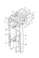
- Fig. 1 is a perspective view illustrating a state where a fuse unit according to an embodiment of the present invention (a fuse unit in which a second fuse element (a strip fuse link) is installed) is installed to a battery.
- Fig. 2 is a perspective view illustrating a state where the fuse unit according to the embodiment of the present invention (a fuse unit in which the second fuse element is not installed) is bent at a flexible hinge.
- Fig. 3(a) is a front view
- Fig. 3(b) is a side view
- Fig. 3(c) is a plan view illustrating a state where the fuse unit according to the embodiment of the present invention (a fuse unit in which the second fuse element is not installed) is bent at the flexible hinge.
- Fig. 1 is a perspective view illustrating a state where a fuse unit according to an embodiment of the present invention (a fuse unit in which a second fuse element (a strip fuse link) is installed) is installed to a battery.
- Fig. 2 is a perspective view illustrating
- FIG. 4 is a perspective view illustrating a state where the fuse unit according to the embodiment of the present invention (a fuse unit in which the second fuse element and element covers are not installed) is not bent at the flexible hinge.
- Fig. 5(a) is a front view
- Fig. 5(b) is a side view
- Fig. 5(c) is a plan view illustrating a state where the fuse unit according to the embodiment of the present invention (a fuse unit in which the second fuse element and the element covers are not installed) is not bent at the flexible hinge.
- Fig. 6 is a perspective view illustrating a state where a busbar of the fuse unit according to the embodiment of the present invention is bent at the flexible hinge.
- Fig. 7(a) is a front view
- Fig. 7(b) is a side view
- Fig. 7(c) is a plan view illustrating a state where the busbar of the fuse unit according to the embodiment of the present invention is bent at the flexible hinge.
- Fig. 8 is a perspective view illustrating the second fuse element used in the fuse unit according to the embodiment of the present invention.
- Fig. 9 is a perspective view illustrating one of the element covers used in the fuse unit according to the embodiment of the present invention.
- Fig. 10 is a perspective view illustrating a bolt used in the fuse unit according to the embodiment of the present invention.
- a fuse unit (a fusible link unit) 1 is connected to a battery 5 (a battery post 7) of a vehicle via, for example, a battery terminal 3, and installed in the vicinity of the battery 5 to be used. Then, electrical equipment such as lights and a starter of the vehicle is connected to the battery through the fuse unit 1.
- the fuse unit 1 is provided with a plate-shaped first body 9 having a predetermined thickness, a plate-shaped second body 11 having a predetermined thickness, a flexible hinge 13, first fuse elements 15, and a second fuse element 17 (see Figs. 1, 2, and 6, for example).
- the first body 9 includes a one end side portion 21 of a busbar (fuse element) 19, and a first resin portion 23 integrally provided in a part of the one end side portion 21.
- the second body 11 is in adjacent to the first body 9, and includes the other end side portion 25 of the busbar 19 and a second resin portion 27 provided integrally in a part of the other end side portion 25.
- the flexible hinge 13 is formed between the first body 9 and the second body 11 (a linear border between the one end side portion 21 and the other end side portion 25 of the busbar 19 without the resin portions 23 and 27).
- Each of the first fuse elements 15 is, for example, a fuse element to be connected to electrical equipment such as a light, is fused at a relatively low current value, formed integrally in the busbar 19 in the one end side portion 21 of the busbar 19, and provided in the first body 9.
- the second fuse element 17 (see Figs. 1 and 8) is higher rating than the first fuse elements 15, and fused at a relatively larger current value.
- the second fuse element 17 is composed of, for example, a strip fuse link to be connected to high-rated electrical equipment such as a starter.
- the second fuse element 17 is provided in the second body in a detachable manner.
- the first body 9 is connected to the battery 5 from above so that the thickness direction thereof is the vertical direction.
- the second body 11 faces a side surface of the battery 5 on the underside of the first body 9.
- the second body 11 is provided with ribs 29 which cover the second fuse element 17.
- a one terminal 31 of the second fuse element 17 is located near the flexible hinge 13 on the side of the flexible hinge 13 (upper side: on the side of the first body 9).
- the other terminal 33 of the second fuse element 17 is located on the side away from the flexible hinge 13 (lower side).
- the second fuse element 17 is installed to the second body 11 in this way.
- the fuse unit 1 is provided with the busbar 19 and a fuse housing 35 as is understood already.
- the fuse housing 35 is formed from a resin with insulation (the first resin portion 23 and the second resin portion 27).
- the busbar 19 is formed by, for example, punching a single flat plate-shaped material having conductivity (for example, metal), and is provided with a battery connection plate 37, a second fuse element connection plate 39, a first circuit connection plate 41, and a second circuit connection plate 43.
- the battery connection plate 37 includes a wide portion 45 and a narrow portion 47, and has a T-shaped configuration. Note that the direction in which the wide portion 45 and the narrow portion 47 are located side by side is regarded as a longitudinal direction of the battery connection plate 37. Also, the direction that intersects at a right angle with the longitudinal direction within a plane of the battery connection plate 37 is regarded as a width direction of the battery connection plate 37.
- the second fuse element connection plate 39 includes a wide portion 49 and a narrow portion 51 and has a T-shaped configuration.
- the direction in which the wide portion 49 (a wide portion which has almost the same width as the wide portion 45 of the battery connection plate 37) and the narrow portion 51 (a narrow portion which has almost the same width as the narrow portion 47 of the battery connection plate 37) are located side by side is regarded as a longitudinal direction of the second fuse element connection plate 39.
- the direction which intersects at a right angle with the longitudinal direction within the plane of the second fuse element connection plate 39 is regarded as a width direction of the fuse element connection plate 39.
- the battery connection plate 37 and the second fuse element connection plate 39 are connected to each other at the narrow portions 47 and 51 thereof.
- the battery connection plate 37 and the second fuse element connection plate 39 make a H-shaped configuration.
- the border between the battery connection plate 37 and the second fuse element connection plate 39 (a connecting portion which extends linearly in the width direction of the battery connection plate 37 and the second fuse element connection plate 39) constitutes the flexible hinge 13.
- the first circuit connection plate 41 is formed into a rectangular shape, and is connected to the battery connection plate 37 (the wide portion 45) through one of the first fuse elements (a fuse element integrally formed in the busbar 19) 15 (15A).
- the first circuit connection plate 41 has a longitudinal direction which coincides with the longitudinal directions of the battery connection plate 37 and the second fuse element connection plate 39, and a width direction which coincides with the width directions of the battery connection plate 37 and the second fuse element connection plate 39.
- the first circuit connection plate 41 is located at a slight distance from the battery connection plate 37 and the second fuse element connection plate 39 on one end side of the battery connection plate 37 and one end side of the second fuse element connection plate 39 in the width directions thereof.
- the second circuit connection plate 43 is formed into a rectangular shape similarly to the first circuit connection plate 41, and is connected to the battery connection plate 37 (the wide portion 45) via the other of the first fuse elements (a fuse element integrally formed in the busbar 19) 15 (15B).
- the second circuit connection plate 43 has a longitudinal direction which coincides with the longitudinal directions of the battery connection plate 37 and the second fuse element connection plate 39, and a width direction which coincides with the width directions of the battery connection plate 37 and the second fuse element connection plate 39.
- the second circuit connection plate 43 is located at a slight distance from the battery connection plate 37 and the second fuse element connection plate 39 on the other end side of the battery connection plate 37 and the other side of the second fuse element connection plate 39 in the width directions thereof.
- An outline shape of the busbar 19 is formed into a rectangular shape.
- the flexible hinge 13 is not only formed in the boundary between the battery connection plate 37 and the second fuse element connection plate 39, but also extended into the first circuit connection plate 41 and the second circuit connection plate 43 (refer to Fig. 6).
- a through hole 53 is provided for connecting the fuse unit 1 to the battery 3.
- a through hole 55 is provided for installing the second fuse element 17.
- a through hole 57 for connecting electrical equipment is provided in the first circuit connection plate 41 .
- a through hole 59 for connecting electrical equipment is provided in the second circuit connection plate 43 .
- the first resin portion 23 is integrally provided in a part of the one end side portion 21 of the busbar 19 by insert molding or the like. More specifically, the first resin portion 23 is provided integrally with the battery connection plate 37, the first circuit connection plate 41, and the second circuit connection plate 43 so that the busbar 19 is exposed in the flexible hinge 13 and the surrounding part thereof, the fuse elements 15 (15A and 15B) and surrounding parts thereof, the through hole 53 for connecting to the battery terminal 3 and the surrounding part thereof, and the through holes 57 and 59 for connecting the electrical equipment and surrounding parts thereof.
- a bolt 61 (see Fig. 10) is inserted so as to have conduction with the first circuit connection plate 41, and further, since the first resin portion 23 is provided, the bolt 61 is fixed to the first circuit connection plate 41.
- a screw portion of the bolt 61 projects from the first resin portion 23 (projects in the thickness direction of the first circuit connection plate 41) and is exposed.
- a bolt 63 (see Fig. 10) is inserted so as to have conduction with the second circuit connection plate 43, and further, since the first resin portion 23 is provided, the bolt 63 is fixed to the second circuit connection plate 43. A screw portion of the bolt 63 projects from the first resin portion 23 and exposed.
- the second resin portion 27 is provided integrally with a part of the other end side portion 25 of the busbar 19 by insert molding or the like. More specifically, the second resin portion 27 is provided integrally with the second fuse element connection plate 39, the first circuit connection plate 41, and the second circuit connection plate 43 so that the busbar 19 is exposed in the flexible hinge 13 and the surrounding part thereof, and the through hole 55 for setting the second fuse element 17 and the surrounding part thereof.
- a bolt 65 (see Fig. 10) is inserted so as to have conduction with the second fuse element connection plate 39, and further, since the second resin portion 27 is provided, the bolt 65 is fixed to the second fuse element connection plate 39.
- a screw portion of the bolt 65 projects from the second resin portion 27 (projects in the thickness direction of the second fuse element connection plate 39) and is exposed.
- the second resin portion 27 is extended from the second fuse element connection plate portion 39 on the side away from the flexible hinge 13. Because of this, the second fuse element connection plate 39 (busbar 19) does not exist on the end side of the second resin portion 27 (on the side away from the flexible hinge 13).
- a bolt 67 (see Fig. 10) is integrally provided on the end side of the second resin portion 27. A screw portion of the bolt 67 projects from the second resin portion 27 and is exposed.
- the fuse unit 1 is formed into a rectangular plate shape having a predetermined thickness when the fuse unit 1 is not bent at the flexible hinge 13 (see Figs. 4 and 5(a) to 5(c)).
- the fuse unit 1 when the fuse unit 1 is bent at the flexible hinge 13, the fuse unit 1 has a L-shaped configuration in which the intersection angle of the first body 9 and the second body 11 is approximately at a right angle (see Figs. 2 and 3(a) to 3(c)).
- the screw portions of the bolts 61, 63, 65, and 67 protrude on a reflex angle side of the flexible hinge 13 (on the side with an angle of 270 degrees), respectively.
- the through hole 53 of the first body 9 (the battery connection plate 37) and the bolts 65 and 67 provided integrally with the second body 11 are centrally located in the width direction of the busbar 19 (the width direction of the fuse unit 1), and are located approximately in line in the longitudinal direction of the busbar 19 (the longitudinal direction of the fuse unit 1).
- a latching portion 69 is provided in the first body 9, and a latched portion 71 is provided in the second body 11.
- the latching portion 69 is engaged with the latched portion 71 and the bent angle of 90 degrees is fixed and maintained.
- the ribs 29 are formed in the second resin portion 27.
- the ribs 29 are formed into a rectangular plate shape, and project to a height which is lower than the respective bolts 65 and 67 of the second fuse element connection plate 39 so that the longitudinal direction thereof coincides with the longitudinal direction of the second fuse element connection plate 39 (the longitudinal direction of the second body 11) and the thickness direction thereof coincides with the width direction of the second fuse element connection plate 39 (the width direction of the second body 11).
- the ribs 29 are provided almost throughout the entire length of the second resin portion 27.
- the ribs 29 are provided as a pair.
- One of the ribs 29 is provided on one end side of the second body 11 in the width direction thereof.
- the other of the ribs 29 is provided on the other end side of the second body 11 in the width direction thereof.
- the bolts 65 and 67 of the second body 11 are located between the pair of ribs 29.
- the distance between the pair of ribs 29 is slightly larger than the outer diameters of nuts and washers to be screwed to the bolts 65 and 67 of the second body 11 (an outer diameter of a tool for tuning the nuts).
- the second fuse element 17 installed in the second body 11 is surrounded by the ribs 29.
- element covers 73 are provided in a detachable manner.
- the element covers 73 are intended to cover the first fuse elements 15 (15A, 15B) of the first body 9 (see Fig. 2).
- the body 75 of the battery 5 is formed into a rectangular parallelepiped, and a battery post 7 stands on one end portion of the upper surface of the body 75.
- the battery terminal 3 is integrally installed in the battery post 7.
- the fuse unit 1 is integrally set to the battery terminal 3 by a stud bolt 77 of the battery terminal 3.
- the first body 9 is located above the battery 5 at a slight distance from the upper surface of the battery 5 (the battery body 75) so that the thickness direction thereof becomes the vertical direction, and the second body 11 faces one side surface of the battery 5 (the battery body 75) at a slight distance away from the side surface of the battery 5 (the battery body 75) on the underside of the first body 9.
- the second fuse element 17 is formed into a bar shape.
- a flat plate-shaped one terminal 31 projects from one end portion of the second fuse element 17.
- the one terminal 31 of the second fuse element 17 is used when setting the second fuse element 17 to the second body 11.
- a through hole 83 is formed in the center area of the one terminal 31 of the second fuse element 17.
- a flat plate-shaped other terminal 33 projects from the other end portion of the second fuse element 17.
- the other terminal 33 of the second fuse element 17 is used when setting the second fuse element 17 to the second body 11.
- a through hole 85 is formed in the center area of the other terminal 33 of the second fuse element.
- the second fuse element 17 is set to the second body 11 in a detachable manner using the bolts 65 and 67 provided in the second body 11.
- the bolt 65 (the bolt which is conductive with the second fuse element connection plate 39) enters the through hole 83 of the one terminal 31 of the second fuse element 17, a nut is screwed to the bolt 65 to tighten the bolt.
- the bolt 67 (the bolt which is not conductive with the second fuse element connection plate 39) enters the through hole 85 of the other terminal 33 of the second fuse element 17, and a nut is screwed to the bolt 67 to tighten the bolt.
- the second fuse element 17 is integrally set to the second body 11.
- the one terminal 31 of the second fuse element 17 is located on the side of the flexible hinge 13 (on the side of the first body 9) in the vicinity of the flexible hinge 13, and the other terminal 33 of the second fuse element 17 is located on the side away from the flexible hinge 13.
- the other terminal 33 of the second fuse element 17 is connected to a starter through a conductive wire.
- the first fuse elements 15 are provided in the first body 9, and the second fuse element 17 having a rated current higher than the first fuse elements 15 is provided in the second body 11 which is distanced from the first body 9 through the flexible hinge 13. Therefore, mutual thermal interference between the first fuse elements 15 and the second fuse element 17 can be avoided. As a result, variation in pre-arcing time-current characteristics of the first fuse elements 15 and the second fuse element 17 can be prevented.
- first fuse elements 15 and the second fuse element 17 are arranged on surfaces at different angles at 90 degrees. Therefore, heat produced by the first fuse elements 15 is released by the first resin portion 23, and further released by air convection. Also, heat produced by the second fuse element 17 is released by the second resin portion 27 and further released by air convection. As a result, the first fuse elements 15 and the second fuse element 17 do not suffer thermal interference from each other, and variation in pre-arcing time-current characteristics of the first fuse elements 15 and the second fuse element 17 can be prevented.
- the fuse unit 1 since the second fuse element 17 is provided in the second body 11 in a detachable manner. Therefore, even if an abnormal current flows in the second fuse element 17 which protects a starter and the second fuse element 17 is fused, only the second fuse element 17 needs to be replaced without replacing the entire fuse unit 1. As a result, the fuse unit 1 can be used at low cost.
- the fuse unit 1 in the state where the fuse unit 1 is set to the battery 5, the second body 11 to which the second fuse element 17 is attached faces a side surface of the battery 5. Therefore, without removing the fuse unit 1 from the battery 5, it is almost impossible to replace the second fuse element 17. Thus, when replacing the second fuse element 17, the fuse unit 1 needs to be removed from the battery 5 (the battery terminal 3). As a result, electric shock hazards can be prevented when replacing the second fuse element 17.
- the ribs 29 which cover the second fuse element 17 are provided in the second body 11.
- the one terminal 31 of the second fuse element 17 is set on the side of the flexible hinge 13, and the other terminal 33 of the second fuse element 17 is set on the side away from the flexible hinge 13.
- the present invention is suitable to a fuse unit which is set in the vicinity of a battery terminal of a vehicle or the like.
Landscapes
- Fuses (AREA)
- Connection Of Batteries Or Terminals (AREA)
Abstract
A fuse unit (1) to be connected to a battery (5) includes a first body (9), a second body (11) adjacent to the first body (9), a flexible hinge (13) formed between the first body (9) and the second body (11), a first fuse element (15) provided in the first body (9), and a second fuse element (17) provided in the second body (11) with a rated current higher than the first fuse element (15).
Description
The present invention relates to a fuse unit and especially to a fuse unit which is installed and used in the vicinity of a battery terminal in a vehicle and the like.
A conventionally known fuse unit is provided with: a busbar having a battery connection plate on one end side, a circuit connection plate on the other end side, and a flexible hinge therebetween; a first resin portion which covers an area of the fuse unit on the side of the battery connection plate; and a second resin portion which covers the circuit connection plate side thereof (refer to JP 2010-040367 A (PTL1)).
In the conventional fuse unit, the battery connection plate is connected to a battery through a battery terminal. Also, in a state where the conventional fuse unit is connected to a battery, the fuse unit has an L-shaped configuration, the area on the side of the battery connection plate from the flexible hinge faces the upper surface of the battery, and the area on the side of the circuit connection plate faces a side surface of the battery.
Also, in the conventional fuse unit, for example, fuse elements (parts made of a low-melting-point metal which are fused by heat when a current of a rated value of higher flows for a given period of time) are provided in the area thereof on the side of the circuit connection plate.
Incidentally, there is a problem in the conventional fuse unit that, since the plurality of fuse elements are provided in the area on the side of the circuit connection plate, thermal interference happens as each of the fuse elements produces heat, thus causing variation in pre-arcing time-current characteristics of each of the fuse elements.
The above-mentioned problem becomes more outstanding if not only a low-rated current fuse element (a fuse element which is fused at a relatively small current value: for example, a fuse element connected to electrical equipment such as light) but also a high-rated current fuse element (a fuse element which is fused at a relatively large current value: for example, a fuse element connected to electrical equipment such as a starter) are provided as fuse elements.
The present invention has been made in view of the above problem, and the object thereof is to provide a fuse unit provided with a plurality of fuse elements, which avoids thermal interference between/among the respective fuse elements, thus enabling to prevent variation in pre-arcing time-current characteristics of the fuse elements.
A fuse unit according to the first aspect of the present invention is a fuse unit to be connected to a battery, including a first body, a second body adjacent to the first body, a flexible hinge formed between the first body and the second body, a first fuse element provided in the first body, and a second fuse element provided in the second body with a rated current higher than the first fuse element.
In the fuse unit according to the first aspect of the present invention, it is preferred that the second fuse element is provided in the second body in a detachable manner, and, when the fuse unit is set to the battery, the first body is connected to the battery above the battery, and the second body comes on the underside of the first body and faces a side surface of the battery.
In the fuse unit according to the first aspect of the present invention, it is preferred that a rib which surrounds the second fuse element is provided in the second body.
In the fuse unit according to the first aspect of the present invention, It is preferred that one terminal of the second fuse element is set on a side of the flexible hinge of the second body, and the other terminal of the second fuse element is set on a side away from the flexible hinge of the second body.
With the fuse unit according to the first aspect of the present invention, in the fuse unit provided with a plurality of fuse elements, thermal interference between the respective fuse elements can be avoided, thus preventing variation in pre-arcing time-current characteristics of the fuse elements.
Hereinafter, an embodiment of the present invention will be explained based on the drawings.
As illustrated in Fig. 1, a fuse unit (a fusible link unit) 1 is connected to a battery 5 (a battery post 7) of a vehicle via, for example, a battery terminal 3, and installed in the vicinity of the battery 5 to be used. Then, electrical equipment such as lights and a starter of the vehicle is connected to the battery through the fuse unit 1.
The fuse unit 1 is provided with a plate-shaped first body 9 having a predetermined thickness, a plate-shaped second body 11 having a predetermined thickness, a flexible hinge 13, first fuse elements 15, and a second fuse element 17 (see Figs. 1, 2, and 6, for example).
As illustrated in Fig. 6, the first body 9 includes a one end side portion 21 of a busbar (fuse element) 19, and a first resin portion 23 integrally provided in a part of the one end side portion 21.
The second body 11 is in adjacent to the first body 9, and includes the other end side portion 25 of the busbar 19 and a second resin portion 27 provided integrally in a part of the other end side portion 25.
The flexible hinge 13 is formed between the first body 9 and the second body 11 (a linear border between the one end side portion 21 and the other end side portion 25 of the busbar 19 without the resin portions 23 and 27).
Each of the first fuse elements 15 is, for example, a fuse element to be connected to electrical equipment such as a light, is fused at a relatively low current value, formed integrally in the busbar 19 in the one end side portion 21 of the busbar 19, and provided in the first body 9.
The second fuse element 17 (see Figs. 1 and 8) is higher rating than the first fuse elements 15, and fused at a relatively larger current value. The second fuse element 17 is composed of, for example, a strip fuse link to be connected to high-rated electrical equipment such as a starter. The second fuse element 17 is provided in the second body in a detachable manner.
As illustrated in Fig. 1, when the fuse unit 1 is installed to the battery 5, the first body 9 is connected to the battery 5 from above so that the thickness direction thereof is the vertical direction. The second body 11 faces a side surface of the battery 5 on the underside of the first body 9.
The second body 11 is provided with ribs 29 which cover the second fuse element 17. A one terminal 31 of the second fuse element 17 is located near the flexible hinge 13 on the side of the flexible hinge 13 (upper side: on the side of the first body 9). The other terminal 33 of the second fuse element 17 is located on the side away from the flexible hinge 13 (lower side). The second fuse element 17 is installed to the second body 11 in this way.
To explain the fuse unit 1 more specifically, the fuse unit 1 is provided with the busbar 19 and a fuse housing 35 as is understood already. The fuse housing 35 is formed from a resin with insulation (the first resin portion 23 and the second resin portion 27).
As illustrated in Fig. 6 and other drawings, the busbar 19 is formed by, for example, punching a single flat plate-shaped material having conductivity (for example, metal), and is provided with a battery connection plate 37, a second fuse element connection plate 39, a first circuit connection plate 41, and a second circuit connection plate 43.
The battery connection plate 37 includes a wide portion 45 and a narrow portion 47, and has a T-shaped configuration. Note that the direction in which the wide portion 45 and the narrow portion 47 are located side by side is regarded as a longitudinal direction of the battery connection plate 37. Also, the direction that intersects at a right angle with the longitudinal direction within a plane of the battery connection plate 37 is regarded as a width direction of the battery connection plate 37. The second fuse element connection plate 39 includes a wide portion 49 and a narrow portion 51 and has a T-shaped configuration. Note that the direction in which the wide portion 49 (a wide portion which has almost the same width as the wide portion 45 of the battery connection plate 37) and the narrow portion 51 (a narrow portion which has almost the same width as the narrow portion 47 of the battery connection plate 37) are located side by side is regarded as a longitudinal direction of the second fuse element connection plate 39. Moreover, the direction which intersects at a right angle with the longitudinal direction within the plane of the second fuse element connection plate 39 is regarded as a width direction of the fuse element connection plate 39.
The battery connection plate 37 and the second fuse element connection plate 39 are connected to each other at the narrow portions 47 and 51 thereof. The battery connection plate 37 and the second fuse element connection plate 39 make a H-shaped configuration. The border between the battery connection plate 37 and the second fuse element connection plate 39 (a connecting portion which extends linearly in the width direction of the battery connection plate 37 and the second fuse element connection plate 39) constitutes the flexible hinge 13.
The first circuit connection plate 41 is formed into a rectangular shape, and is connected to the battery connection plate 37 (the wide portion 45) through one of the first fuse elements (a fuse element integrally formed in the busbar 19) 15 (15A). The first circuit connection plate 41 has a longitudinal direction which coincides with the longitudinal directions of the battery connection plate 37 and the second fuse element connection plate 39, and a width direction which coincides with the width directions of the battery connection plate 37 and the second fuse element connection plate 39. The first circuit connection plate 41 is located at a slight distance from the battery connection plate 37 and the second fuse element connection plate 39 on one end side of the battery connection plate 37 and one end side of the second fuse element connection plate 39 in the width directions thereof.
The second circuit connection plate 43 is formed into a rectangular shape similarly to the first circuit connection plate 41, and is connected to the battery connection plate 37 (the wide portion 45) via the other of the first fuse elements (a fuse element integrally formed in the busbar 19) 15 (15B). The second circuit connection plate 43 has a longitudinal direction which coincides with the longitudinal directions of the battery connection plate 37 and the second fuse element connection plate 39, and a width direction which coincides with the width directions of the battery connection plate 37 and the second fuse element connection plate 39. The second circuit connection plate 43 is located at a slight distance from the battery connection plate 37 and the second fuse element connection plate 39 on the other end side of the battery connection plate 37 and the other side of the second fuse element connection plate 39 in the width directions thereof.
An outline shape of the busbar 19 is formed into a rectangular shape. The flexible hinge 13 is not only formed in the boundary between the battery connection plate 37 and the second fuse element connection plate 39, but also extended into the first circuit connection plate 41 and the second circuit connection plate 43 (refer to Fig. 6).
In the battery connection plate 37, a through hole 53 is provided for connecting the fuse unit 1 to the battery 3. In the second fuse element connection plate 39, a through hole 55 is provided for installing the second fuse element 17.
In the first circuit connection plate 41, a through hole 57 for connecting electrical equipment is provided. In the second circuit connection plate 43, a through hole 59 for connecting electrical equipment is provided.
The first resin portion 23 is integrally provided in a part of the one end side portion 21 of the busbar 19 by insert molding or the like. More specifically, the first resin portion 23 is provided integrally with the battery connection plate 37, the first circuit connection plate 41, and the second circuit connection plate 43 so that the busbar 19 is exposed in the flexible hinge 13 and the surrounding part thereof, the fuse elements 15 (15A and 15B) and surrounding parts thereof, the through hole 53 for connecting to the battery terminal 3 and the surrounding part thereof, and the through holes 57 and 59 for connecting the electrical equipment and surrounding parts thereof.
As illustrated in Fig. 2, in the through hole 57 of the first circuit connection plate 41, a bolt 61 (see Fig. 10) is inserted so as to have conduction with the first circuit connection plate 41, and further, since the first resin portion 23 is provided, the bolt 61 is fixed to the first circuit connection plate 41. A screw portion of the bolt 61 projects from the first resin portion 23 (projects in the thickness direction of the first circuit connection plate 41) and is exposed.
In the through hole 59 of the second circuit connection plate 43, a bolt 63 (see Fig. 10) is inserted so as to have conduction with the second circuit connection plate 43, and further, since the first resin portion 23 is provided, the bolt 63 is fixed to the second circuit connection plate 43. A screw portion of the bolt 63 projects from the first resin portion 23 and exposed.
The second resin portion 27 is provided integrally with a part of the other end side portion 25 of the busbar 19 by insert molding or the like. More specifically, the second resin portion 27 is provided integrally with the second fuse element connection plate 39, the first circuit connection plate 41, and the second circuit connection plate 43 so that the busbar 19 is exposed in the flexible hinge 13 and the surrounding part thereof, and the through hole 55 for setting the second fuse element 17 and the surrounding part thereof.
In the through hole 55 of the second fuse element connection plate 39, a bolt 65 (see Fig. 10) is inserted so as to have conduction with the second fuse element connection plate 39, and further, since the second resin portion 27 is provided, the bolt 65 is fixed to the second fuse element connection plate 39. A screw portion of the bolt 65 projects from the second resin portion 27 (projects in the thickness direction of the second fuse element connection plate 39) and is exposed.
Moreover, as understood from comparison between Figs. 2 and 6, the second resin portion 27 is extended from the second fuse element connection plate portion 39 on the side away from the flexible hinge 13. Because of this, the second fuse element connection plate 39 (busbar 19) does not exist on the end side of the second resin portion 27 (on the side away from the flexible hinge 13). On the end side of the second resin portion 27, a bolt 67 (see Fig. 10) is integrally provided. A screw portion of the bolt 67 projects from the second resin portion 27 and is exposed.
The fuse unit 1 is formed into a rectangular plate shape having a predetermined thickness when the fuse unit 1 is not bent at the flexible hinge 13 (see Figs. 4 and 5(a) to 5(c)). On the other hand, when the fuse unit 1 is bent at the flexible hinge 13, the fuse unit 1 has a L-shaped configuration in which the intersection angle of the first body 9 and the second body 11 is approximately at a right angle (see Figs. 2 and 3(a) to 3(c)).
The screw portions of the bolts 61, 63, 65, and 67 protrude on a reflex angle side of the flexible hinge 13 (on the side with an angle of 270 degrees), respectively.
The through hole 53 of the first body 9 (the battery connection plate 37) and the bolts 65 and 67 provided integrally with the second body 11 are centrally located in the width direction of the busbar 19 (the width direction of the fuse unit 1), and are located approximately in line in the longitudinal direction of the busbar 19 (the longitudinal direction of the fuse unit 1).
Also, as illustrated in Figs. 5(a) to 5(c), a latching portion 69 is provided in the first body 9, and a latched portion 71 is provided in the second body 11. When the busbar 19 is bent at the flexible hinge 13 at 90 degrees, the latching portion 69 is engaged with the latched portion 71 and the bent angle of 90 degrees is fixed and maintained.
The ribs 29 are formed in the second resin portion 27. The ribs 29 are formed into a rectangular plate shape, and project to a height which is lower than the respective bolts 65 and 67 of the second fuse element connection plate 39 so that the longitudinal direction thereof coincides with the longitudinal direction of the second fuse element connection plate 39 (the longitudinal direction of the second body 11) and the thickness direction thereof coincides with the width direction of the second fuse element connection plate 39 (the width direction of the second body 11).
The ribs 29 are provided almost throughout the entire length of the second resin portion 27. The ribs 29 are provided as a pair. One of the ribs 29 is provided on one end side of the second body 11 in the width direction thereof. The other of the ribs 29 is provided on the other end side of the second body 11 in the width direction thereof. The bolts 65 and 67 of the second body 11 are located between the pair of ribs 29. The distance between the pair of ribs 29 is slightly larger than the outer diameters of nuts and washers to be screwed to the bolts 65 and 67 of the second body 11 (an outer diameter of a tool for tuning the nuts).
The second fuse element 17 installed in the second body 11 is surrounded by the ribs 29.
In the fuse unit 1, element covers 73 (see Fig. 9) are provided in a detachable manner. The element covers 73 are intended to cover the first fuse elements 15 (15A, 15B) of the first body 9 (see Fig. 2).
As illustrated in Fig. 1, the body 75 of the battery 5 is formed into a rectangular parallelepiped, and a battery post 7 stands on one end portion of the upper surface of the body 75. The battery terminal 3 is integrally installed in the battery post 7.
The fuse unit 1 is integrally set to the battery terminal 3 by a stud bolt 77 of the battery terminal 3.
In a state where the fuse unit 1 is integrally set to the battery 5 via the battery terminal 3, the first body 9 is located above the battery 5 at a slight distance from the upper surface of the battery 5 (the battery body 75) so that the thickness direction thereof becomes the vertical direction, and the second body 11 faces one side surface of the battery 5 (the battery body 75) at a slight distance away from the side surface of the battery 5 (the battery body 75) on the underside of the first body 9.
As illustrated in Fig. 8, the second fuse element 17 is formed into a bar shape. A flat plate-shaped one terminal 31 projects from one end portion of the second fuse element 17. The one terminal 31 of the second fuse element 17 is used when setting the second fuse element 17 to the second body 11. A through hole 83 is formed in the center area of the one terminal 31 of the second fuse element 17.
A flat plate-shaped other terminal 33 projects from the other end portion of the second fuse element 17. The other terminal 33 of the second fuse element 17 is used when setting the second fuse element 17 to the second body 11. A through hole 85 is formed in the center area of the other terminal 33 of the second fuse element.
The second fuse element 17 is set to the second body 11 in a detachable manner using the bolts 65 and 67 provided in the second body 11.
Namely, the bolt 65 (the bolt which is conductive with the second fuse element connection plate 39) enters the through hole 83 of the one terminal 31 of the second fuse element 17, a nut is screwed to the bolt 65 to tighten the bolt. Also, the bolt 67 (the bolt which is not conductive with the second fuse element connection plate 39) enters the through hole 85 of the other terminal 33 of the second fuse element 17, and a nut is screwed to the bolt 67 to tighten the bolt. In this way, the second fuse element 17 is integrally set to the second body 11.
As already understood, in a state where the second fuse element 17 is set to the second body 11, the one terminal 31 of the second fuse element 17 is located on the side of the flexible hinge 13 (on the side of the first body 9) in the vicinity of the flexible hinge 13, and the other terminal 33 of the second fuse element 17 is located on the side away from the flexible hinge 13.
The other terminal 33 of the second fuse element 17 is connected to a starter through a conductive wire.
According to the fuse unit 1, the first fuse elements 15 are provided in the first body 9, and the second fuse element 17 having a rated current higher than the first fuse elements 15 is provided in the second body 11 which is distanced from the first body 9 through the flexible hinge 13. Therefore, mutual thermal interference between the first fuse elements 15 and the second fuse element 17 can be avoided. As a result, variation in pre-arcing time-current characteristics of the first fuse elements 15 and the second fuse element 17 can be prevented.
This means that the first fuse elements 15 and the second fuse element 17 are arranged on surfaces at different angles at 90 degrees. Therefore, heat produced by the first fuse elements 15 is released by the first resin portion 23, and further released by air convection. Also, heat produced by the second fuse element 17 is released by the second resin portion 27 and further released by air convection. As a result, the first fuse elements 15 and the second fuse element 17 do not suffer thermal interference from each other, and variation in pre-arcing time-current characteristics of the first fuse elements 15 and the second fuse element 17 can be prevented.
Moreover, according to the fuse unit 1, since the second fuse element 17 is provided in the second body 11 in a detachable manner. Therefore, even if an abnormal current flows in the second fuse element 17 which protects a starter and the second fuse element 17 is fused, only the second fuse element 17 needs to be replaced without replacing the entire fuse unit 1. As a result, the fuse unit 1 can be used at low cost.
Moreover, according to the fuse unit 1, in the state where the fuse unit 1 is set to the battery 5, the second body 11 to which the second fuse element 17 is attached faces a side surface of the battery 5. Therefore, without removing the fuse unit 1 from the battery 5, it is almost impossible to replace the second fuse element 17. Thus, when replacing the second fuse element 17, the fuse unit 1 needs to be removed from the battery 5 (the battery terminal 3). As a result, electric shock hazards can be prevented when replacing the second fuse element 17.
Moreover, according to the fuse unit 1, the ribs 29 which cover the second fuse element 17 are provided in the second body 11. Thus, without removing the fuse unit 1 from the battery 5, it is even more difficult to replace the second fuse element 17. As a result, electric shock hazards can be prevented more definitely when replacing the second fuse element 17.
Moreover, according to the fuse unit 1, the one terminal 31 of the second fuse element 17 is set on the side of the flexible hinge 13, and the other terminal 33 of the second fuse element 17 is set on the side away from the flexible hinge 13. Hence, without removing the fuse unit 1 from the battery 5, a tool does not reach a nut which fixes the other terminal 33 of the second fuse element 17, which makes even more difficult to replace the fuse element 17. As a result, electric shock hazards can be prevented more definitely when replacing the second fuse element 17.
The present invention is suitable to a fuse unit which is set in the vicinity of a battery terminal of a vehicle or the like.
Claims (4)
- A fuse unit to be connected to a battery, comprising:
a first body;
a second body adjacent to the first body;
a flexible hinge formed between the first body and the second body;
a first fuse element provided in the first body; and
a second fuse element provided in the second body with a rated current higher than the first fuse element. - The fuse unit according to claim 1, wherein
the second fuse element is provided in the second body in a detachable manner, and
the fuse unit is structured such that, when the fuse unit is set to the battery, the first body is connected to the battery above a battery body, and the second body comes on the underside of the first body and faces a side surface of the battery body. - The fuse unit according to claim 1, wherein a rib which surrounds the second fuse element is provided in the second body.
- The fuse unit according to claim 1, wherein one terminal of the second fuse element is set on a side of the flexible hinge of the second body, and the other terminal of the second fuse element is set on a side away from the flexible hinge of the second body.
Priority Applications (2)
| Application Number | Priority Date | Filing Date | Title |
|---|---|---|---|
| CN201280015496.9A CN103460328B (en) | 2011-04-01 | 2012-02-24 | fuse |
| DE112012001544.4T DE112012001544B4 (en) | 2011-04-01 | 2012-02-24 | Fuse unit |
Applications Claiming Priority (2)
| Application Number | Priority Date | Filing Date | Title |
|---|---|---|---|
| JP2011081631A JP5753426B2 (en) | 2011-04-01 | 2011-04-01 | Fuse unit |
| JP2011-081631 | 2011-04-01 |
Publications (1)
| Publication Number | Publication Date |
|---|---|
| WO2012132213A1 true WO2012132213A1 (en) | 2012-10-04 |
Family
ID=45955055
Family Applications (1)
| Application Number | Title | Priority Date | Filing Date |
|---|---|---|---|
| PCT/JP2012/001271 Ceased WO2012132213A1 (en) | 2011-04-01 | 2012-02-24 | Fuse unit |
Country Status (4)
| Country | Link |
|---|---|
| JP (1) | JP5753426B2 (en) |
| CN (1) | CN103460328B (en) |
| DE (1) | DE112012001544B4 (en) |
| WO (1) | WO2012132213A1 (en) |
Citations (3)
| Publication number | Priority date | Publication date | Assignee | Title |
|---|---|---|---|---|
| EP1124246A2 (en) * | 2000-02-09 | 2001-08-16 | Yazaki Corporation | Fuse unit and method of manufacturing fuse unit |
| US20020168566A1 (en) * | 2001-05-01 | 2002-11-14 | Yazaki Corporation | Battery connecting portion-protecting cover |
| JP2010040367A (en) | 2008-08-06 | 2010-02-18 | Yazaki Corp | Battery direct attachment fuse unit |
Family Cites Families (7)
| Publication number | Priority date | Publication date | Assignee | Title |
|---|---|---|---|---|
| US5790007A (en) * | 1995-03-23 | 1998-08-04 | Sumitomo Wiring Systems, Ltd. | Board fuse, and method of manufacturing the board fuse |
| JPH10275554A (en) * | 1997-03-28 | 1998-10-13 | Yazaki Corp | fuse |
| JP4198255B2 (en) * | 1999-02-08 | 2008-12-17 | 株式会社三英社製作所 | Branch unit with built-in fuse |
| JP4083991B2 (en) * | 2000-02-09 | 2008-04-30 | 矢崎総業株式会社 | Fuse unit and manufacturing method thereof |
| JP5074989B2 (en) * | 2008-04-03 | 2012-11-14 | 矢崎総業株式会社 | Fusible link mounting structure |
| JP5437689B2 (en) | 2009-04-17 | 2014-03-12 | 矢崎総業株式会社 | Fusible link unit |
| JP5277061B2 (en) | 2009-04-17 | 2013-08-28 | 矢崎総業株式会社 | Fusible link unit |
-
2011
- 2011-04-01 JP JP2011081631A patent/JP5753426B2/en active Active
-
2012
- 2012-02-24 DE DE112012001544.4T patent/DE112012001544B4/en active Active
- 2012-02-24 WO PCT/JP2012/001271 patent/WO2012132213A1/en not_active Ceased
- 2012-02-24 CN CN201280015496.9A patent/CN103460328B/en active Active
Patent Citations (3)
| Publication number | Priority date | Publication date | Assignee | Title |
|---|---|---|---|---|
| EP1124246A2 (en) * | 2000-02-09 | 2001-08-16 | Yazaki Corporation | Fuse unit and method of manufacturing fuse unit |
| US20020168566A1 (en) * | 2001-05-01 | 2002-11-14 | Yazaki Corporation | Battery connecting portion-protecting cover |
| JP2010040367A (en) | 2008-08-06 | 2010-02-18 | Yazaki Corp | Battery direct attachment fuse unit |
Also Published As
| Publication number | Publication date |
|---|---|
| JP2012216453A (en) | 2012-11-08 |
| DE112012001544T5 (en) | 2013-12-24 |
| CN103460328A (en) | 2013-12-18 |
| JP5753426B2 (en) | 2015-07-22 |
| DE112012001544B4 (en) | 2021-11-25 |
| CN103460328B (en) | 2015-11-25 |
Similar Documents
| Publication | Publication Date | Title |
|---|---|---|
| US7592892B2 (en) | Fusible link unit accommodated in in-vehicle electrical connection box | |
| US7978046B2 (en) | Fusible link unit | |
| CN103650210B (en) | Fuse unit | |
| JP4917927B2 (en) | Multiple fuse unit for vehicles | |
| JP6007012B2 (en) | Fuse unit | |
| JP2018010768A (en) | Multiple fuse | |
| EP1777724A1 (en) | Electric junction box | |
| US9941086B2 (en) | Electrical component unit, fusible link unit, and fixing structure | |
| JP5328459B2 (en) | Fuse unit | |
| KR20160031531A (en) | Direct-battery-mount fusible link | |
| US9203170B2 (en) | Pin header | |
| KR20150041036A (en) | Fuse unit | |
| KR101979226B1 (en) | Busbar for multi-fuse | |
| JP2016071937A (en) | Battery terminal | |
| CN119050611A (en) | Fuse unit | |
| JP6210736B2 (en) | Fuse unit | |
| JP2004127704A (en) | Fusible link unit | |
| JP5878028B2 (en) | Blade fuse | |
| CN103460328B (en) | fuse | |
| KR20030023753A (en) | Busbar connecting terminal | |
| JP2017004874A (en) | Terminal block | |
| JP7662396B2 (en) | Connection structure of battery terminal and battery terminal block | |
| KR20130003867U (en) | Fuse having jumping function | |
| KR20170096354A (en) | Voltage sensing moddule and manufacturing method thereof | |
| JP7123482B2 (en) | fusible link unit |
Legal Events
| Date | Code | Title | Description |
|---|---|---|---|
| 121 | Ep: the epo has been informed by wipo that ep was designated in this application |
Ref document number: 12714393 Country of ref document: EP Kind code of ref document: A1 |
|
| WWE | Wipo information: entry into national phase |
Ref document number: 112012001544 Country of ref document: DE Ref document number: 1120120015444 Country of ref document: DE |
|
| 122 | Ep: pct application non-entry in european phase |
Ref document number: 12714393 Country of ref document: EP Kind code of ref document: A1 |