JP2017004874A - Terminal block - Google Patents
Terminal block Download PDFInfo
- Publication number
- JP2017004874A JP2017004874A JP2015119799A JP2015119799A JP2017004874A JP 2017004874 A JP2017004874 A JP 2017004874A JP 2015119799 A JP2015119799 A JP 2015119799A JP 2015119799 A JP2015119799 A JP 2015119799A JP 2017004874 A JP2017004874 A JP 2017004874A
- Authority
- JP
- Japan
- Prior art keywords
- terminal
- housing
- terminal block
- electric wire
- types
- Prior art date
- Legal status (The legal status is an assumption and is not a legal conclusion. Google has not performed a legal analysis and makes no representation as to the accuracy of the status listed.)
- Pending
Links
Images
Abstract
Description
本発明は、端子台に関する。 The present invention relates to a terminal block.
従来、車両に搭載されるバッテリの電力を、車両内の回路に供給するための端子台が知られている(例えば、特許文献1参照)。このような端子台の多くは、回路から延びる端子付き電線の一端に設けられた丸端子等の接続端子が電気的かつ機械的に接続される電線接続部がハウジングに設けられている。また、ハウジングには、例えば接続端子を電線接続部に接続する際の端子付き電線の動きや、車両の振動による端子付き電線の動きを規制するための構造が設けられていることがある。このような構造の一例として、ハウジングに、端子付き電線を挟む一対の凸部を設けることで、端子付き電線の太さ方向の動きを規制するという規制構造が挙げられる。 Conventionally, a terminal block for supplying electric power of a battery mounted on a vehicle to a circuit in the vehicle is known (see, for example, Patent Document 1). Many of such terminal blocks are provided with a wire connecting portion in which a connection terminal such as a round terminal provided at one end of a terminal-attached electric wire extending from a circuit is electrically and mechanically connected. In addition, the housing may be provided with a structure for regulating the movement of the electric wire with terminal when the connection terminal is connected to the electric wire connecting portion and the movement of the electric wire with terminal due to vibration of the vehicle, for example. As an example of such a structure, there is a restriction structure in which movement of the terminal-attached electric wire in the thickness direction is restricted by providing the housing with a pair of convex portions sandwiching the electric wire with the terminal.
ここで、上述した規制構造が、端子付き電線を挟む一対の凸部を設けるという構造であることから、このような規制構造を有する端子台では、取付け可能な端子付き電線の太さが限られがちである。一方で、車両においては、太さが異なる複数種類の端子付き電線が使われることが多い。そして、各種類の端子付き電線の太さに応じた規制構造を有する複数種類の端子台を個別に用意すると、端子付き電線の車両への搭載コストが増大する恐れがある。 Here, since the restriction structure described above is a structure in which a pair of convex portions sandwiching the electric wire with terminal is provided, the thickness of the electric wire with terminal that can be attached is limited in the terminal block having such a restriction structure. Tend to. On the other hand, in vehicles, a plurality of types of electric wires with terminals having different thicknesses are often used. If a plurality of types of terminal blocks having a restriction structure corresponding to the thickness of each type of terminal-attached electric wire are individually prepared, there is a risk that the cost of mounting the terminal-attached electric wire on the vehicle increases.
従って、本発明は、上記のような問題点に着目し、太さが異なる複数種類の端子付き電線を、搭載コストを抑えて車両に搭載することができる端子台を提供することを目的とする。 Accordingly, the present invention focuses on the above-described problems, and an object thereof is to provide a terminal block capable of mounting a plurality of types of terminals-attached electric wires having different thicknesses on a vehicle at a reduced mounting cost. .
上記課題を解決するために、請求項1に記載の発明は、ハウジングと、前記ハウジングに設けられ、一端に接続端子が設けられた端子付き電線における前記接続端子が電気的かつ機械的に接続される電線接続部と、前記端子付き電線を間に挟む一対の凸部を有する規制部材と、を備え、前記規制部材が、前記ハウジングとは別体に形成されて該ハウジングに取り付けられることを特徴とする端子台となっている。 In order to solve the above-mentioned problem, the invention according to claim 1 is an electrical and mechanical connection between a housing and an electric wire with a terminal provided in the housing and provided with a connection terminal at one end. And a regulating member having a pair of convex portions sandwiching the terminal-attached electric wire therebetween, and the regulating member is formed separately from the housing and attached to the housing. It is a terminal block.
請求項2に記載の発明は、請求項1に記載の端子台において、前記規制部材が、互いに太さが異なる複数種類の前記端子付き電線それぞれの太さに応じた間隔を開けて前記一対の凸部が配置されるように形成された複数種類の規制部材の中から、前記電線接続部に前記接続端子が接続される前記端子付き電線の太さに応じて1種類の規制部材が選択され、該規制部材が前記ハウジングに1又は複数個取り付けられるものであることを特徴とする。 According to a second aspect of the present invention, in the terminal block according to the first aspect, the regulating member is configured to have the pair of the pair of electric wires with different thicknesses at intervals corresponding to the thicknesses of the terminal-attached electric wires. One type of regulating member is selected from among a plurality of types of regulating members formed so that the convex portions are arranged according to the thickness of the terminal-attached electric wire to which the connection terminal is connected to the electric wire connecting portion. One or a plurality of the regulating members are attached to the housing.
請求項3に記載の発明は、請求項2に記載の端子台において、前記複数種類の規制部材は、互いに同じ形状の係止部が、互いに同じ位置に設けられたものであり、前記ハウジングには、前記係止部が係止する被係止部が設けられていることを特徴とする。 According to a third aspect of the present invention, in the terminal block according to the second aspect, the plurality of types of restricting members are provided with locking portions having the same shape at the same position, Is provided with a locked portion to be locked by the locking portion.
請求項1に記載の発明によれば、端子台において、上記の規制部材が、ハウジングとは別体に形成されてハウジングに取り付けられる。このため、端子台において、規制部材以外の構造については、その殆どを複数種類の端子付き電線に対して共通の構造とすることができる。これにより、太さが異なる複数種類の端子付き電線を、搭載コストを抑えて車両に搭載することができる。 According to the first aspect of the present invention, in the terminal block, the restriction member is formed separately from the housing and attached to the housing. For this reason, in a terminal block, about structures other than a control member, most can be made into a common structure with respect to multiple types of electric wire with a terminal. As a result, a plurality of types of electric wires with terminals having different thicknesses can be mounted on the vehicle at a reduced mounting cost.
また、請求項2に記載の発明によれば、使用可能性の高低に依らず多くの種類の規制部材を用意しておき、所望の規制部材を選択するという運用が可能となる。これにより、搭載可能な端子付き電線の種類について自由度を高めることができる。 Further, according to the invention described in claim 2, it is possible to perform an operation in which many types of regulating members are prepared and a desired regulating member is selected regardless of the level of usability. Thereby, a freedom degree can be raised about the kind of electric wire with a terminal which can be mounted.
また、請求項3に記載の発明によれば、ハウジングに対する規制部材の取付け構造が、規制部材の種類に依らず共通となるので、規制部材以外の構造について、複数種類の端子付き電線に対してほぼ完全に共通の構造とすることができる。これにより、太さが異なる複数種類の端子付き電線を、搭載コストを一層抑えて車両に搭載することができる。 Further, according to the invention described in claim 3, the attachment structure of the restriction member to the housing is common regardless of the type of the restriction member. The structure can be almost completely common. As a result, a plurality of types of terminal-attached electric wires having different thicknesses can be mounted on the vehicle at a further reduced installation cost.
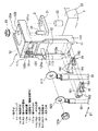
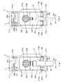
本発明の一実施形態の端子台について図1〜図2を参照して説明する。図1は、本発明の一実施形態の端子台を示す斜視図であり、図2は、図1に示されている端子台の正面図を、互いに幅が異なる2種類の端子付き電線について個別に示す図である。 A terminal block according to an embodiment of the present invention will be described with reference to FIGS. FIG. 1 is a perspective view showing a terminal block according to an embodiment of the present invention, and FIG. 2 is a front view of the terminal block shown in FIG. 1 for two types of electric wires with different terminals. FIG.
本実施形態の端子台1は、バッテリ2から、バッテリ端子3を介して供給される電力を、不図示の回路に供給するためのものである。 The terminal block 1 of this embodiment is for supplying the electric power supplied from the battery 2 via the battery terminal 3 to a circuit (not shown).
バッテリ2の上面21には電極ポスト22が突出して設けられており、この電極ポスト22にバッテリ端子3が固定される。バッテリ端子3は、概ね直方体形状に形成されており、一端に電極ポスト22が挿通する挿通孔31が設けられ、他端に端子台1を固定するためのボルト32が立設されている。挿通孔31は不図示の機構によって縮径されるようになっており、電極ポスト22が挿通した状態で挿通孔31を縮径することにより、電極ポスト22にバッテリ端子3が固定される。
An
端子台1は、樹脂製のハウジング11が、導電性金属で形成された次のような板金構造物12を覆い固めた(モールディングした)構造を有している。板金構造物12は、回路端子121(電線接続部)と給電端子122とを備えている。
The terminal block 1 has a structure in which a
回路端子121は、導電性金属で矩形板状に形成され、その中央に、回路が接続される端子ボルト121aが立設されている。ここで、回路端子121の端子ボルト121aには、互いに太さの異なる2種類の端子付き電線51,52のうち何れかの端子付き電線51,52の一端に設けられた接続端子511,521がナット締めにより固定される。本実施形態では、接続端子511,521は丸端子になっており、この接続端子511,521を貫通した端子ボルト121aにナット121bが締め付けられることで、回路端子121に接続端子511,521が面で接触した状態で締結される。
The
給電端子122は、導電性金属で矩形板状に形成され、その中央に、バッテリ端子3のボルト32が貫通する貫通孔122aが設けられている。この貫通孔122aを貫通したボルト32にナット33が締め付けられることで、給電端子122がバッテリ端子3に固定される。この給電端子122に、バッテリ端子3を介して電極ポスト22からの電力が供給される。
The
また、回路端子121における給電端子122側の端縁の一端から延びる柱状部121bと、給電端子122における回路端子121側の端縁の、上記柱状部121bとは反対側の一端から延びる柱状部122bとが、可溶体123によって電気的に接続されている。閾値以上の電流が流れるとこの可溶体123が溶断することにより、回路に過剰な電流が流れることが回避される。そして、回路端子121と給電端子122と可溶体123とからなる板金構造物12が絶縁樹脂のハウジング11に、各端子の接続面が露出され、窓111の内側に可溶体123が位置するように設けられている。
Further, the
絶縁樹脂のハウジング11は、回路端子121と給電端子122と可溶体123とからなる概ねL字状の板金構造物12を覆うようにL字状に形成される。回路端子121、給電端子122における柱状部122b、及び可溶体123を覆う部分が長尺に形成され、この部分に可溶体123の溶断視認用の窓111が設けられ、透明カバー13が被せられる。
The
また、ハウジング11における長尺側は、回路端子121に沿って延在する矩形状の壁部112と、この壁部112における幅方向の両側縁に立設された2つの側壁113を備えている。そして、回路端子121の下方における2つの側壁113の相互間に、回路端子121に接続端子511,521が接続される端子付き電線51,52の太さ方向D1の移動を規制する規制部材14,15が取り付けられるようになっている。
The long side of the
規制部材14,15は、ハウジング11とは別体に形成され、帯板部分141,151と、端子付き電線51,52の太さに応じた間隔を開けてその両端に配置された一対の凸部142,152とを有している。本実施形態では、この規制部材14,15が、2種類の端子付き電線51,52それぞれの太さに対応するように2種類用意されている。即ち、相対的に太い端子付き電線51に対応した太線用の規制部材14として、その太い端子付き電線51の太さに応じた間隔を開けて一対の凸部142が配置されたものが用意されている。また、相対的に細い端子付き電線52に対応した細線用の規制部材15として、その細い端子付き電線52の太さに応じた間隔を開けて一対の凸部152が配置されたものが用意されている。
The restricting
そして、それら2種類の規制部材14,15の中から、回路端子121に接続端子511,521が接続される端子付き電線51,52の太さに応じて選択された1種類の規制部材が、ハウジング11に1個取り付けられる。ここで、2種類の規制部材14,15には、互いに同じ形状の係止部143,153が、互いに同じ位置に設けられている。即ち、係止部143,153は、一対の凸部142,152それぞれの側面から突出した突起となっている。
And one kind of regulating member selected according to the thickness of the
ハウジング11の2つの側壁113には、各規制部材14,15の係止部143,153が嵌入することで係止する穴が被係止部113aとして設けられている。上記のように端子付き電線51,52の太さに応じて選択された規制部材14,15が、係止部143,153の被係止部113aへの係止により、ハウジング11に取り付けられる。
The two
図2(a)には、太い端子付き電線51に応じて選択された太線用の規制部材14がハウジング11に取り付けられて構成された端子台1が示されている。また、図2(b)には、細い端子付き電線52に応じて選択された細線用の規制部材15がハウジング11に取り付けられて構成された端子台1が示されている。これらの規制部材14,15は、接続端子511,521を貫通した端子ボルト121aにナット121bを締め付ける際に、端子付き電線51,52の回転を規制する回り止めの役割を果たす。また、規制部材14,15は、回路端子121への締結後、車両の振動による端子付き電線51,52の動きを規制する役割も果たす。
FIG. 2A shows the terminal block 1 configured by attaching the thick
以上に説明した本実施形態の端子台1によれば、上記の規制部材14,15が、ハウジング11とは別体に形成されてハウジング11に取り付けられる。このため、端子台1において、規制部材14,15以外の構造については、互いに太さの異なる2種類の端子付き電線51,52に対して共通の構造とすることができる。これにより、2種類の端子付き電線51,52を、搭載コストを抑えて車両に搭載することができる。
According to the terminal block 1 of the present embodiment described above, the
また、本実施形態の端子台1によれば、上記の2種類の規制部材14,15以外にも、凸部の間隔の異なる複数種類の規制部材を用意しておき、所望の規制部材を選択するという運用が可能となる。これにより、搭載可能な端子付き電線の種類について自由度を高めることができる。
In addition, according to the terminal block 1 of the present embodiment, in addition to the two kinds of
また、本実施形態の端子台1によれば、ハウジング11に対する規制部材14,15の取付け構造が、規制部材14,15の種類に依らず共通となる。このため、規制部材14,15以外(特にハウジング11)の構造について、2種類の端子付き電線51,52に対してほぼ完全に共通の構造とすることができる。これにより、2種類の端子付き電線51,52を、搭載コストを一層抑えて車両に搭載することができる。
Moreover, according to the terminal block 1 of this embodiment, the attachment structure of the regulating
尚、以上に説明した実施形態は本発明の代表的な形態を示したに過ぎず、本発明は、これらの実施形態に限定されるものではない。即ち、本発明の骨子を逸脱しない範囲で種々変形して実施することができる。かかる変形によってもなお本発明の端子台の構成を具備する限り、勿論、本発明の範疇に含まれるものである。 In addition, embodiment described above showed only the typical form of this invention, and this invention is not limited to these embodiment. That is, various modifications can be made without departing from the scope of the present invention. Of course, such modifications are included in the scope of the present invention as long as the configuration of the terminal block of the present invention is provided.
例えば、上述した実施形態では、本発明にいう端子台の一例として、可溶体123を介して電力を回路に供給するいわゆるヒュージブルリンクとしての端子台1が例示されている。しかしながら、本発明にいう端子台は、これに限るものではなく、例えば可溶体を備えない単純な端子台であってもよい。
For example, in the above-described embodiment, as an example of the terminal block according to the present invention, the terminal block 1 as a so-called fusible link that supplies power to the circuit via the
また、上述した実施形態では、本発明にいう規制部材の一例として、互いに太さの異なる2種類の端子付き電線51,52に対応した太線用と細線用との2種類の規制部材14,15が例示されている。しかしながら、本発明にいう規制部材はこれに限るものではなく、一対の凸部の間隔が互いに異なる3種類以上の規制部材等であってもよい。
Moreover, in embodiment mentioned above, as an example of the regulating member referred to in the present invention, two types of regulating
また、上述した実施形態では、本発明にいう規制部材の一例として、2種類の規制部材14,15の中から選択された1種類の規制部材がハウジング11に1個取り付けられる形態が例示されている。しかしながら、本発明にいう規制部材はこれに限るものではなく、例えば、選択された1種類の規制部材がハウジングに複数個取り付けられる形態であってもよい。
Moreover, in embodiment mentioned above, the form by which one type of regulating member selected from two types of regulating
また、上述した実施形態では、本発明にいう係止部の一例として、規制部材14,15の側面から突出した係止突起としての係止部143,153が例示されている。また、本発明にいう被係止部の一例として、係止部143,153が嵌入する穴としての被係止部113aが例示されている。しかしながら、本発明にいう係止部及び被係止部はこれに限るものではない。本発明にいう被係止部は、ハウジングにおける2つの側壁に、内側に向かって突出するように設けた突起としての被係止部であってもよい。また、本発明にいう係止部は、これら突起としての被係止部が嵌入するように規制部材に設けられた穴としての係止部であってもよい。
Moreover, in embodiment mentioned above, the latching | locking
1 端子台
11 ハウジング
12 板金構造物
13 透明カバー
14,15 規制部材
121 回路端子(電線接続部)
121a 端子ボルト
122 給電端子
113a 被係止部
141,151 帯板部分
142,152 一対の凸部
143,153 係止部
D1 太さ方向
DESCRIPTION OF SYMBOLS 1
Claims (3)
前記ハウジングに設けられ、一端に接続端子が設けられた端子付き電線における前記接続端子が電気的かつ機械的に接続される電線接続部と、
前記端子付き電線を間に挟む一対の凸部を有する規制部材と、を備え、
前記規制部材が、前記ハウジングとは別体に形成されて該ハウジングに取り付けられることを特徴とする端子台。 A housing;
An electric wire connecting portion provided in the housing and electrically and mechanically connected to the connecting terminal in the electric wire with a terminal provided with a connecting terminal at one end;
A regulating member having a pair of convex portions sandwiching the electric wire with terminal therebetween,
The terminal block, wherein the restricting member is formed separately from the housing and attached to the housing.
前記ハウジングには、前記係止部が係止する被係止部が設けられていることを特徴とする請求項2に記載の端子台。 The plurality of types of regulating members are provided with locking portions having the same shape at the same position,
The terminal block according to claim 2, wherein the housing is provided with a locked portion that is locked by the locking portion.
Priority Applications (1)
| Application Number | Priority Date | Filing Date | Title |
|---|---|---|---|
| JP2015119799A JP2017004874A (en) | 2015-06-12 | 2015-06-12 | Terminal block |
Applications Claiming Priority (1)
| Application Number | Priority Date | Filing Date | Title |
|---|---|---|---|
| JP2015119799A JP2017004874A (en) | 2015-06-12 | 2015-06-12 | Terminal block |
Publications (1)
| Publication Number | Publication Date |
|---|---|
| JP2017004874A true JP2017004874A (en) | 2017-01-05 |
Family
ID=57753545
Family Applications (1)
| Application Number | Title | Priority Date | Filing Date |
|---|---|---|---|
| JP2015119799A Pending JP2017004874A (en) | 2015-06-12 | 2015-06-12 | Terminal block |
Country Status (1)
| Country | Link |
|---|---|
| JP (1) | JP2017004874A (en) |
Cited By (2)
| Publication number | Priority date | Publication date | Assignee | Title |
|---|---|---|---|---|
| CN110611201A (en) * | 2018-09-30 | 2019-12-24 | 中航光电科技股份有限公司 | Wiring connector |
| US11394138B2 (en) | 2018-11-22 | 2022-07-19 | Autonetworks Technologies, Ltd. | Terminal block and wire routing unit |
-
2015
- 2015-06-12 JP JP2015119799A patent/JP2017004874A/en active Pending
Cited By (2)
| Publication number | Priority date | Publication date | Assignee | Title |
|---|---|---|---|---|
| CN110611201A (en) * | 2018-09-30 | 2019-12-24 | 中航光电科技股份有限公司 | Wiring connector |
| US11394138B2 (en) | 2018-11-22 | 2022-07-19 | Autonetworks Technologies, Ltd. | Terminal block and wire routing unit |
Similar Documents
| Publication | Publication Date | Title |
|---|---|---|
| US8821190B2 (en) | Fuse unit | |
| US10269522B2 (en) | Fuse unit | |
| JP6770358B2 (en) | Multiple fuse | |
| JP5150291B2 (en) | Electrical junction box | |
| JP2011165494A (en) | Fuse unit | |
| JP2004127703A (en) | Fusible link unit | |
| WO2016190075A1 (en) | Power storage module | |
| WO2015029708A1 (en) | Direct-battery-mount fusible link | |
| JP2016131118A (en) | Electrical component unit, fusible link unit, and fixing structure | |
| JP5147606B2 (en) | Fuse block | |
| JP2017004874A (en) | Terminal block | |
| WO2018016348A1 (en) | Capacitor | |
| JP6575930B2 (en) | Board unit | |
| JP2016018613A (en) | Terminal connection structure | |
| JP6227371B2 (en) | Relief terminal block, relief terminal block and frame assembly | |
| JP6273122B2 (en) | Cassette and electric junction box having the same | |
| JP2012252818A (en) | Fusible link | |
| JP2017097980A (en) | Wiring module | |
| KR20160072046A (en) | Fusible link | |
| JP7123482B2 (en) | fusible link unit | |
| JP2017050091A (en) | Battery terminal block | |
| JP6555889B2 (en) | Fuse unit | |
| WO2021020255A1 (en) | Electronic module | |
| JP2003087940A (en) | Electric junction box | |
| JP2005276494A (en) | Fuse holder and fuse unit |
Legal Events
| Date | Code | Title | Description |
|---|---|---|---|
| RD04 | Notification of resignation of power of attorney |
Free format text: JAPANESE INTERMEDIATE CODE: A7424 Effective date: 20180202 |