WO2012132185A1 - Dispositif d'émission-réception - Google Patents
Dispositif d'émission-réception Download PDFInfo
- Publication number
- WO2012132185A1 WO2012132185A1 PCT/JP2012/000648 JP2012000648W WO2012132185A1 WO 2012132185 A1 WO2012132185 A1 WO 2012132185A1 JP 2012000648 W JP2012000648 W JP 2012000648W WO 2012132185 A1 WO2012132185 A1 WO 2012132185A1
- Authority
- WO
- WIPO (PCT)
- Prior art keywords
- signal
- transmission
- unit
- frequency
- correction coefficient
- Prior art date
Links
Images


Classifications
-
- H—ELECTRICITY
- H04—ELECTRIC COMMUNICATION TECHNIQUE
- H04B—TRANSMISSION
- H04B1/00—Details of transmission systems, not covered by a single one of groups H04B3/00 - H04B13/00; Details of transmission systems not characterised by the medium used for transmission
- H04B1/38—Transceivers, i.e. devices in which transmitter and receiver form a structural unit and in which at least one part is used for functions of transmitting and receiving
- H04B1/40—Circuits
-
- H—ELECTRICITY
- H04—ELECTRIC COMMUNICATION TECHNIQUE
- H04L—TRANSMISSION OF DIGITAL INFORMATION, e.g. TELEGRAPHIC COMMUNICATION
- H04L27/00—Modulated-carrier systems
- H04L27/26—Systems using multi-frequency codes
- H04L27/2601—Multicarrier modulation systems
- H04L27/2626—Arrangements specific to the transmitter only
- H04L27/2627—Modulators
- H04L27/2634—Inverse fast Fourier transform [IFFT] or inverse discrete Fourier transform [IDFT] modulators in combination with other circuits for modulation
- H04L27/2636—Inverse fast Fourier transform [IFFT] or inverse discrete Fourier transform [IDFT] modulators in combination with other circuits for modulation with FFT or DFT modulators, e.g. standard single-carrier frequency-division multiple access [SC-FDMA] transmitter or DFT spread orthogonal frequency division multiplexing [DFT-SOFDM]
-
- H—ELECTRICITY
- H04—ELECTRIC COMMUNICATION TECHNIQUE
- H04L—TRANSMISSION OF DIGITAL INFORMATION, e.g. TELEGRAPHIC COMMUNICATION
- H04L25/00—Baseband systems
- H04L25/02—Details ; arrangements for supplying electrical power along data transmission lines
- H04L25/06—Dc level restoring means; Bias distortion correction ; Decision circuits providing symbol by symbol detection
- H04L25/068—Dc level restoring means; Bias distortion correction ; Decision circuits providing symbol by symbol detection by sampling faster than the nominal bit rate
-
- H—ELECTRICITY
- H04—ELECTRIC COMMUNICATION TECHNIQUE
- H04L—TRANSMISSION OF DIGITAL INFORMATION, e.g. TELEGRAPHIC COMMUNICATION
- H04L27/00—Modulated-carrier systems
- H04L27/32—Carrier systems characterised by combinations of two or more of the types covered by groups H04L27/02, H04L27/10, H04L27/18 or H04L27/26
- H04L27/34—Amplitude- and phase-modulated carrier systems, e.g. quadrature-amplitude modulated carrier systems
- H04L27/36—Modulator circuits; Transmitter circuits
- H04L27/366—Arrangements for compensating undesirable properties of the transmission path between the modulator and the demodulator
- H04L27/367—Arrangements for compensating undesirable properties of the transmission path between the modulator and the demodulator using predistortion
-
- H—ELECTRICITY
- H04—ELECTRIC COMMUNICATION TECHNIQUE
- H04L—TRANSMISSION OF DIGITAL INFORMATION, e.g. TELEGRAPHIC COMMUNICATION
- H04L27/00—Modulated-carrier systems
- H04L27/32—Carrier systems characterised by combinations of two or more of the types covered by groups H04L27/02, H04L27/10, H04L27/18 or H04L27/26
Definitions
- the present invention relates to a transmission / reception apparatus for transmitting / receiving a signal modulated using a single carrier transmission system.
- a signal that is PSK or QAM modulated at 1.76 G symbols / second is transmitted.
- One symbol time is as short as about 0.57 nsec.
- a radio frequency (RF) circuit that up-converts a modulated baseband signal to a 60 GHz band and transmits it from an antenna
- broadband communication characteristics are required. Since the signal bandwidth is 1.76 GHz and is a wide band, the transmission band characteristic of the RF circuit is required to be flat over the entire band of the signal for transmission without causing signal distortion.
- a method for correcting distortion of passband characteristics in an RF circuit As a method for correcting distortion of passband characteristics in an RF circuit, a method of predistorting using a digital baseband signal is known. In this method, the passband characteristic of the RF circuit is measured in advance, a digital filter coefficient that is the inverse characteristic of the measurement result is obtained, and the transmission signal is filtered to correct the passband characteristic when passing through the RF circuit. Is given.
- Patent Documents 1 and 2 are known as wireless communication systems using predistortion.
- the wireless communication device described in Patent Document 1 detects a frequency distortion characteristic of a signal obtained by looping back an RF circuit from a transmission side to a reception side, holds a time axis signal obtained by performing an inverse Fourier transform on a difference spectrum from an ideal characteristic, Distortion is corrected by adding to the FIR filter at the time of transmission.
- the digital wireless communication device described in Patent Document 2 performs predistortion on the frequency domain signal.
- the digital wireless communication device performs N-point Fourier transform on the time axis signal oversampled L times by inserting zero samples, and weights the signal in the frequency domain. After weighting, the digital wireless communication device shifts the frequency bin to change the center frequency, and converts it into a time axis signal by N-point inverse Fourier transform and outputs it.
- the conventional wireless communication apparatus has the following problems. Specifically, in the above-described prior art, it is necessary to apply a predistortion filter to a signal obtained by oversampling (interpolating) a symbol of a transmission signal in a DA converter.
- the conventional wireless communication device is to be applied to millimeter wave communication, it is necessary to use a digital filter with respect to a time axis signal of 3.52 Gsps (samples / second) even with, for example, double oversampling.
- the present invention has been made in consideration of such circumstances, and since the symbol rate is high, even a baseband signal having a wide signal bandwidth has a high passband characteristic without increasing the circuit scale. It is an object of the present invention to provide a transmission / reception device that corrects accuracy.
- the transmitting / receiving apparatus includes a high frequency unit that frequency-converts a signal modulated using a single carrier transmission method, and a correction that corrects distortion by multiplying a frequency domain signal by a distortion correction coefficient in the frequency conversion of the high frequency unit.
- a coefficient multiplier a first converter that converts a time-axis signal into a frequency-domain signal at the time of reception, and converts a frequency-domain signal that has been distortion-corrected by the correction coefficient multiplier at the time of transmission into a time-axis signal;
- a second conversion unit that converts the axis signal into a frequency domain signal and converts the frequency domain signal that has been subjected to distortion correction by the correction coefficient multiplication unit at the time of reception into a time axis signal.
- the correction coefficient multiplication unit, the first conversion unit, and the second conversion unit at the time of reception can be shared, and transmission can be performed without greatly increasing the circuit scale.
- Band characteristics can be corrected with high accuracy.
- Block diagram showing the overall configuration of the transceiver Block diagram showing the internal configuration of the distortion correction unit Explanatory drawing showing an example of the frame format of a transmission signal
- Block diagram showing the internal configuration of the distortion correction unit during calibration of transmission distortion characteristics The figure which expressed the signal of each part of a distortion amendment part at the time of calibration with a spectrum, (A) The spectrum of the baseband signal inputted into AD converter, (B) After the AD converter oversampled the baseband signal twice The spectrum of the signal, (C) the spectrum of the frequency domain signal obtained by converting the sample string by 128-point FFT, and (D) the spectrum of the frequency domain signal corresponding to the inverse characteristic of the distortion characteristic Block diagram showing the internal configuration of the distortion correction unit during transmission The figure which expressed each signal in the distortion correction part at the time of transmission with a spectrum, (A) Spectrum of the modulation signal of the symbol rate fs from a modulation part, (B) Spectrum of the frequency domain signal which converted the sample sequence by 64 point FFT , (C) spectrum of frequency domain signal
- the transmission / reception apparatus according to the present invention is applied to a transmission / reception apparatus that transmits and receives millimeter-wave band radio signals.
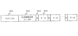
- FIG. 3 is an explanatory diagram illustrating an example of a frame format of a transmission signal.
- the frame format of the transmission signal includes a preamble 401, a transmission path estimation field 402, a guard interval (GI) 403, and data 404.
- GI guard interval
- the preamble 401 includes a waveform obtained by repeating a known signal waveform a plurality of times.
- the preamble 401 uses a waveform obtained by repeating a signal waveform of one unit a plurality of times with a signal waveform obtained by BPSK modulation of a 128-bit Golay sequence having excellent correlation characteristics as a unit.
- the transmission / reception apparatus obtains repetition of a known signal waveform by correlation detection, and uses it for synchronization processing including at least one of frame detection, gain control, and carrier frequency synchronization.
- the transmission path estimation field 402 includes a plurality of known signal waveforms, and is used for transmission path distortion estimation in the transmission / reception apparatus according to the present invention.
- the transmission path estimation field 402 uses a signal waveform obtained by BPSK modulation of a 128-bit Golay sequence and a complementary sequence of the Golay sequence.
- the guard interval 403 is inserted as a delimiter of the data 404.
- a known signal waveform for example, a signal obtained by BPSK modulation of a 64-bit Golay sequence is also used for the guard interval 403.
- the data 404 includes a symbol string obtained by PSK or QAM modulation of a data bit string that has been subjected to error correction coding for each block.
- the symbol sequence of the transmission signal digitally modulated using the frame format (signal format) described above is subjected to a root raised cosine filter as a transmission band limiting filter and converted to an analog baseband signal by a DA converter.
- the baseband signal is converted into a single carrier high frequency signal in a high frequency (RF) section (see FIG. 1) and transmitted from the antenna.
- RF high frequency
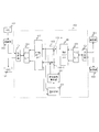
- FIG. 1 is a block diagram illustrating the overall configuration of the transmission / reception device 10.
- the transmission / reception device 10 includes an antenna 301, a high frequency unit (RF unit) 302, an AD converter 201, a synchronization unit 303, a distortion correction unit 102, a demodulation unit 304, a DA converter 101, and a modulation unit 103. It is.
- the RF unit 302 has a configuration on the transmission side for up-converting a signal that has been single-carrier modulated by the modulation unit 103, and a configuration on the reception side for down-converting a single-carrier high-frequency signal received by the antenna 301. including.
- the distortion correction unit 102 corrects transmission distortion characteristics received on the transmission side of the RF unit 302 by the symbol sequence digitally modulated (single carrier modulation) by the modulation unit 103 and outputs the correction to the DA converter 101.
- the DA converter 101 converts the output signal from the distortion correction unit 102 into an analog baseband signal.
- the transmission side of the RF unit 302 up-converts the analog baseband signal into a single carrier high-frequency signal and transmits it through the antenna 301.
- the receiving side of the RF unit 302 down-converts the single carrier high frequency signal received by the antenna 301 and converts it into a baseband signal.
- the reception side of the RF unit 302 outputs a baseband signal to the AD converter 201.
- the AD converter 201 samples an output signal from the reception side of the RF unit 302 and converts it into a digital signal.
- the synchronization unit 303 performs synchronization processing including at least one of frame detection, gain adjustment of the RF unit 302, and carrier frequency synchronization using the preamble 401 in the received signal of the converted digital signal.
- the distortion correction unit 102 estimates the transmission path distortion using the transmission path estimation field 402 according to the frame timing detected by the synchronization unit 303, corrects the distortion characteristics of the transmission path of the data 404 thereafter and the symbol string. Is output.
- the demodulator 304 receives the symbol sequence output from the distortion corrector 102, determines signal points, demodulates data, and reproduces transmission data.
- FIG. 2 is a block diagram showing the internal configuration of the distortion correction unit 102.
- the distortion correction unit 102 includes a switching unit C1, a parallel / serial conversion unit 104, a PN point inverse Fourier / Fourier conversion unit 105, a correction coefficient multiplication unit 106 (106-1 to 106-n), a correction unit,
- the configuration includes a coefficient calculation unit 107, a distortion estimation unit 202, an N-point Fourier / inverse Fourier transform unit 108, a serial / parallel conversion unit 109, and a switching unit C2.
- the switching unit C1 outputs a reception signal from the synchronization unit 303 to the parallel / serial conversion unit 104 during reception or calibration, and outputs a transmission signal from the parallel / serial conversion unit 104 to the DA converter 101 during transmission. Switch the transmission path.
- the parallel / serial converter 104 converts a serial signal into a parallel signal at the time of reception or calibration, and converts the parallel signal into a serial signal at the time of transmission.
- the PN point inverse Fourier / Fourier transform unit 105 as the first transform unit performs Fourier transform or inverse Fourier transform by using a P ⁇ N point frequency domain signal or time axis signal as a unit and by sign inversion of the rotor operation.
- the PN point inverse Fourier / Fourier transform unit 105 performs a Fourier transform using a time axis signal of P ⁇ N points as a unit and converts it to a frequency domain signal of P ⁇ N points.
- the PN point inverse Fourier / Fourier transform unit 105 performs inverse Fourier transform with a P ⁇ N point frequency domain signal as a unit to convert it into a P ⁇ N point time axis signal.
- the switching unit C2 outputs a reception signal from the serial / parallel conversion unit 109 to the demodulation unit 304 at the time of reception or calibration, and outputs a transmission signal from the modulation unit 103 to the serial / parallel conversion unit 109 at the time of transmission. Switch the transmission path.
- the serial / parallel converter 109 converts a parallel signal into a serial signal at the time of reception or calibration, and converts from a serial signal to a parallel signal at the time of transmission.
- the N-point Fourier / inverse Fourier transform unit 108 as the second transform unit performs Fourier transform or inverse Fourier transform in units of the N-point time axis signal or frequency domain signal so that it can be realized by sign inversion of the rotor operation. .
- the N-point Fourier / inverse Fourier transform unit 108 performs inverse Fourier transform in units of N-point frequency domain signals at the time of reception or calibration, and converts them into N-point time axis signals.
- the N-point Fourier / inverse Fourier transform unit 108 performs Fourier transform in units of N-point time axis signals at the time of transmission, and transforms them into N-point frequency domain signals.
- the distortion correction unit 102 can share each unit by changing the signal processing direction at any timing of transmission, reception, and calibration.
- reception distortion characteristic for example, a reference signal is input from the measuring device to the reception side of the RF unit 302, the reception distortion characteristic is measured using the same method as described later, and the reception distortion correction coefficient is calculated. It is possible to ask.
- FIG. 4 is a block diagram showing an internal configuration of the distortion correction unit 102 at the time of calibration of transmission distortion characteristics.
- the switching unit C1 is omitted.
- the DA converter 101 receives a reference signal having a known signal waveform, for example, from the outside of the transmission / reception device 10 and outputs it to the transmission side of the RF unit 302, and further loops back via the reception side of the RF unit 302. The same signal is input to the AD converter 201. That is, a loopback signal from the transmission side of the RF unit 302 to the reception side of the RF unit 302 is input to the RF unit 302.
- the reference signal may be any signal as long as it has a known signal waveform, for example, a modulated signal of the preamble 401 of the transmission signal.
- a sine wave signal having an arbitrary frequency may be used.
- it is a wideband signal that can measure the frequency characteristics of the signal band of the transmission signal, or a signal obtained by frequency sweeping a sine wave narrowband signal within the signal band.
- the AD converter 201 inputs and samples a reference signal obtained by looping back the RF unit 302, and outputs the sampled digital signal to the parallel / serial conversion unit 104 via the synchronization unit 303 and the switching unit C1.
- the parallel / serial converter 104 converts the input digital signal (serial signal) into a parallel signal and outputs the parallel signal to the PN point inverse Fourier / Fourier transformer 105.
- the PN point inverse Fourier / Fourier transform unit 105 performs Fourier transform on the time axis signal, which is an input signal from the parallel / serial conversion unit 104, and converts it into a frequency domain signal.
- the PN point inverse Fourier / Fourier transform unit 105 selects a signal band signal from the frequency domain signal and outputs the selected signal to the distortion estimation unit 202.
- the distortion estimation unit 202 corrects the frequency domain signal of the input signal band using the reception distortion characteristics of the RF unit 302 obtained in advance, and then corrects the frequency domain signal after correction and the frequency domain of a known reference signal.
- a difference vector from the signal is obtained for each frequency bin (range). The difference vector corresponds to the transmission distortion characteristic on the transmission side of the RF unit 302.
- the correction coefficient calculation unit 107 obtains a correction vector that is the inverse characteristic of the estimated transmission distortion characteristic based on the transmission distortion characteristic estimated by the distortion estimation unit 202, and stores the transmission distortion correction coefficient corresponding to the correction vector. . Furthermore, the correction coefficient calculation unit 107 may weight the correction vector for each frequency bin using the frequency domain characteristic of the root raised cosine filter obtained in advance as the transmission band limiting filter.
- FIG. 5 is a diagram in which signals of each part of the distortion correction unit 102 at the time of calibration are expressed by a spectrum.
- the reference signal for calibration is a signal having the same bandwidth fs (Hz) as that of the transmission signal.
- FIG. 5A shows the spectrum of the baseband signal input to the AD converter 201.
- the baseband signal is a complex signal and has a spectrum with a bandwidth fs (Hz) centering on a DC (0 Hz) component.
- FIG. 5B shows the spectrum of the signal after the AD converter 201 oversamples the baseband signal twice.
- the sampling rate is 2 fs (Hz), and aliasing occurs around fs (Hz).
- FIG. 5C shows a spectrum of a frequency domain signal obtained by converting a sample string by a 128-point FFT.
- the difference between the signal band characteristic 700 (see FIG. 5C) and the ideal frequency characteristic 701 (dotted line) is the transmission distortion characteristic with respect to the frequency bin of 64 points in the signal band. It becomes.
- the correction coefficient calculation unit 107 obtains a transmission distortion correction coefficient 702 (solid line) that is a reverse characteristic of the transmission distortion characteristic, and stores it in the correction coefficient calculation unit 107.
- the transmission signal x (t), the loopback reception signal r (t), the passband characteristic h_tx (t) on the transmission side of the RF unit 302, and the passband characteristic h_rx (t) on the reception side of the RF unit 302 are used.
- Equation (1) is obtained.
- x_ref (t) is a reference signal for calibration
- X_ref (f) is a value obtained by Fourier transforming x_ref (t)
- r_ref (t) and r_ref (t) are reference signals looped back to the reception side of the RF unit 302.
- the passband characteristic H (f) of the RF unit 302 is obtained by Expression (2).
- the communication band characteristic H_tx (f) on the transmission side of the RF unit 302 is obtained as represented by Equation (3).
- 1 / H_tx (f) is obtained as a transmission distortion correction coefficient 702 (see FIG. 7) which is a reverse characteristic of the transmission distortion characteristic by calibration of the distortion correction unit 102.
- FIG. 6 is a block diagram illustrating an internal configuration of the distortion correction unit 102 at the time of transmission.
- the switching unit C2 is omitted.
- the serial / parallel converter 109 receives a symbol string (serial signal) modulated at the symbol rate fs (Hz) from the modulator 103 via the switching unit C2, and converts it into a parallel signal every N symbols. To do.
- the N-point Fourier / inverse Fourier transform unit 108 performs Fourier transform on the input N-symbol signal, which is a parallel signal, and converts it into an N-point frequency domain signal that can be configured by a complex vector for each frequency bin.
- the N-point Fourier / inverse Fourier transform unit 108 converts the N-point frequency domain signal into the P-point (P> 1) oversampling necessary when the DA converter 101 converts the analog signal into an analog signal. Band extension to P ⁇ N points.
- the N-point Fourier / inverse Fourier transform unit 108 generates a complex vector in the signal band of the frequency bin in another band of the same frequency bin in order to generate an alias component of the signal band corresponding to oversampling. make a copy.
- the correction coefficient multiplying unit 106 applies the transmission distortion correction coefficient obtained by the correction coefficient calculating unit 107 to the frequency domain signal band-extended to P ⁇ N points by the N point Fourier / inverse Fourier transform unit 108 for each frequency bin. Multiply.
- the correction coefficient multiplication unit 106 outputs the multiplication result to the PN point inverse Fourier / Fourier transform unit 105.
- the PN point inverse Fourier / Fourier transform unit 105 performs inverse Fourier transform on the multiplication result from the correction coefficient multiplication unit 106, that is, the P ⁇ N point frequency domain signal multiplied by the transmission distortion correction coefficient, to obtain a time axis signal. Convert.
- the PN point inverse Fourier / Fourier transform unit 105 outputs the time axis signal to the parallel / serial conversion unit 104.
- the time axis signal is a sample sequence that has been oversampled P times with respect to the original N symbol sequence.
- a sample string of P ⁇ N samples is converted into a serial signal by the parallel / serial converter 104.
- the parallel / serial conversion unit 104 removes the first partial sample and the last few samples that are affected by the FFT and IFFT waveform truncation from the P ⁇ N samples, for example, a central P ⁇ N / 2 sample. Output a sample sequence.
- N symbols to be corrected are input while overlapping each other by N / 2 symbols from the symbol string input from the modulation unit 103 to the distortion correction unit 102. Thereby, the continuity of the sample sequence output from the distortion correction unit 102 is maintained.
- FIG. 7 is a diagram representing each signal in the distortion correction unit 102 by a spectrum.
- FIG. 7A shows the spectrum of the modulation signal from the modulation unit 103 at the symbol rate fs (Hz). Since the symbol rate fs (Hz) and the sample rate are the same sample sequence, the aliasing occurs at fs / 2 (Hz) in FIG.
- FIG. 7B shows a spectrum of a frequency domain signal obtained by transforming a sample string by 64-point FFT.
- FIG. 7C shows a spectrum of a frequency domain signal whose band is expanded by double oversampling for each frequency bin.
- the N-point Fourier / inverse Fourier transform unit 108 when the frequency band is expanded to 128 points by double oversampling, the N-point Fourier / inverse Fourier transform unit 108 generates an alias component of the signal in the original signal band with respect to the frequency bin that becomes the alias frequency. Copy the signal band component.
- FIG. 7D shows the spectrum of the signal of the transmission distortion correction coefficient 601.
- the transmission distortion correction coefficient 601 includes the characteristics of a root raised cosine filter (RRC filter)
- the multiplication also serves as a transmission band limiting filter.
- the PN point inverse Fourier / Fourier transform unit 105 performs inverse Fourier transform on the corrected frequency domain signal in 128-point IFFT to convert it into a time axis signal, and outputs it to the DA converter 101 via the switching unit C1.
- the input time-axis signal is converted into an analog signal in the DA converter 101, the spectrum of the baseband signal shown in FIG. 7F is obtained.
- the baseband signal is modulated using the single carrier frequency fc.
- FIG. 7G shows a spectrum of a frequency domain signal in which distortion on the transmission side of the RF unit is corrected.
- the correction coefficient multiplication unit 106 converts the frequency Rx filter characteristic C_filt (f) into the frequency domain signal X ′ (f) (see FIG. 7D) obtained by over-sampling the transmission signal x (t) by Fourier transform. ) And a correction coefficient 1 / H_tx (f) for correcting the passband characteristic on the transmission side of the RF unit 302, to obtain a signal X ′′ (f) represented by Expression (4) (FIG. 7E). reference).
- the PN point inverse Fourier / Fourier transform unit 105 performs inverse Fourier transform on the signal X ′′ (f) obtained by Equation (4) to obtain a time axis signal x ′′ (t) (see FIG. 7F).
- the time axis signal x ′′ (t) is transmitted from the antenna 301 via the transmission side of the RF unit 302.
- the signal x ′′ ′′ (t) is expressed by Equation (5).
- the transmission / reception device 10 can correct a signal distortion generated on the transmission side of the RF unit 302 and transmit a signal multiplied by a transmission filter (see FIG. 7G).
- FIG. 7G shows a spectrum of a signal in which the distortion of the RF transmitter is corrected.
- FIG. 8 is an explanatory diagram showing an example of a processing unit of a signal to be corrected.
- a sample (symbol) column 501 of the same sampling rate with the same symbol rate and sample rate is input.
- the serial / parallel converter 109 selects a sample sequence 502-1 of 64 samples corresponding to 64 symbols from the sample sequence 501.
- a 64-point Fourier transform and distortion correction are performed on each selected sample string 502 by the distortion correction unit 102, and the 128-sample (64 symbols) time-axis signal 503 is oversampled twice by the 128-point inverse Fourier transform. Converted.
- the partial sample sequence 504-1 of the center 64 samples (32 symbols) is selected and output.
- Sample columns 502-2 and 502-3 are similarly processed and converted into sample columns 504-2 and 504-3.
- the transmitting / receiving apparatus 10 performs FDE (Frequency Domain Equalization) using the distortion correction unit 102 as an equalizer at the time of reception, and measures the pass band of the RF unit at the time of calibration. Furthermore, according to the transmission / reception apparatus 10, it is used as a frequency domain filter that performs interpolation (oversampling) and predistortion (distortion correction) during transmission.
- FDE Frequency Domain Equalization
- the passband characteristic of the transmission RF circuit can be corrected with high accuracy without significantly increasing the circuit scale. Therefore, since the symbol rate is high, even the baseband signal having a wide signal bandwidth can correct the passband characteristic with high accuracy without increasing the circuit scale. Further, the processing clock speed can be lowered by parallelizing the signal processing.
- Each configuration according to the embodiment may be realized as an LSI which is an integrated circuit.
- the LSI may be made into one chip, or a part or all of each component may be made into one chip.
- LSI depending on the degree of integration, it may be referred to as IC, system LSI, super LSI, or ultra LSI.
- circuit integration is not limited to LSI, and circuit integration may be performed using a dedicated circuit or a general-purpose processor.
- an FPGA Field Programmable Gate Array
- a reconfigurable processor that can reconfigure the connection and setting of circuit cells inside the LSI may be used.
- these functional blocks can be performed using, for example, a DSP or a CPU. Further, these processing steps can be recorded on a recording medium as a program and executed.
- the present invention can be widely applied to all wireless communication devices including mobile communication that requires a small circuit scale and low power consumption as a transmission distortion compensation circuit used for single carrier communication.
- the present invention is a transmission / reception apparatus that transmits and receives a signal modulated using a single carrier transmission system, and has high symbol speed, so even a baseband signal having a wide signal bandwidth can be used without increasing the circuit scale.
- the passband characteristic can be corrected well, which is useful.
Abstract
La présente invention permet de corriger de manière précise des caractéristiques de bande passante sans augmentation de l'échelle de circuit, même pour des signaux en bande de base ayant une largeur de bande de signal qui recouvre une large bande en conséquence d'une fréquence de symbole de haute vitesse. Durant une émission, une séquence de symboles qui été modulée à l'aide d'une fréquence de symbole (fs) (Hz) à partir d'une unité de modulation (103) est injectée en entrée, puis convertie en un signal parallèle tous les N symboles dans une unité de conversion série/parallèle (109). Le signal à N symboles subit une transformation de Fourier dans une unité de transformée de Fourier à N points/transformée de Fourier inverse (108), et est converti en un signal en domaine fréquentiel à N points. La largeur de bande de signal à N points est élargie à P×N points. Pour chaque cellule de fréquence, une unité de multiplication de coefficient de correction (106) multiplie le signal en domaine fréquentiel ayant la largeur de bande élargie à P×N points par un coefficient de correction de distorsion d'émission obtenu dans une unité de calcul de coefficient de correction (107). Le signal en domaine fréquentiel à P×N points qui a été multiplié par le coefficient de correction de distorsion d'émission subit une transformation de Fourier inverse dans une unité de transformée de Fourier inverse/transformée de Fourier à P×N points (105) et est converti en un signal dans l'axe du temps.
Priority Applications (1)
| Application Number | Priority Date | Filing Date | Title |
|---|---|---|---|
| US13/814,914 US9065538B2 (en) | 2011-03-30 | 2012-01-31 | Transmission-reception device |
Applications Claiming Priority (2)
| Application Number | Priority Date | Filing Date | Title |
|---|---|---|---|
| JP2011-075832 | 2011-03-30 | ||
| JP2011075832A JP5599353B2 (ja) | 2011-03-30 | 2011-03-30 | 送受信装置 |
Publications (1)
| Publication Number | Publication Date |
|---|---|
| WO2012132185A1 true WO2012132185A1 (fr) | 2012-10-04 |
Family
ID=46929982
Family Applications (1)
| Application Number | Title | Priority Date | Filing Date |
|---|---|---|---|
| PCT/JP2012/000648 WO2012132185A1 (fr) | 2011-03-30 | 2012-01-31 | Dispositif d'émission-réception |
Country Status (3)
| Country | Link |
|---|---|
| US (1) | US9065538B2 (fr) |
| JP (1) | JP5599353B2 (fr) |
| WO (1) | WO2012132185A1 (fr) |
Families Citing this family (3)
| Publication number | Priority date | Publication date | Assignee | Title |
|---|---|---|---|---|
| WO2015125194A1 (fr) * | 2014-02-21 | 2015-08-27 | パナソニック インテレクチュアル プロパティ コーポレーション オブ アメリカ | Appareil d'émission, appareil de réception, procédé d'émission et procédé de réception |
| US9949259B2 (en) * | 2015-05-07 | 2018-04-17 | Qualcomm Incorporated | System and method for transmitting data payload in WB SC, aggregate SC, duplicate SC, OFDM transmission frames |
| US20200304171A1 (en) * | 2020-06-09 | 2020-09-24 | Intel Corporation | Dispersive waveguide crosstalk mitigation |
Citations (3)
| Publication number | Priority date | Publication date | Assignee | Title |
|---|---|---|---|---|
| JP2000244370A (ja) * | 1999-02-22 | 2000-09-08 | Sony Corp | 無線通信装置の送信部の非線形歪補償方法および無線通信装置 |
| JP2007195056A (ja) * | 2006-01-20 | 2007-08-02 | Matsushita Electric Ind Co Ltd | 歪み補償装置及び歪み補償方法 |
| JP2010252178A (ja) * | 2009-04-17 | 2010-11-04 | Nippon Telegr & Teleph Corp <Ntt> | ディジタル無線通信装置 |
Family Cites Families (9)
| Publication number | Priority date | Publication date | Assignee | Title |
|---|---|---|---|---|
| US5612978A (en) * | 1995-05-30 | 1997-03-18 | Motorola, Inc. | Method and apparatus for real-time adaptive interference cancellation in dynamic environments |
| US7133825B2 (en) * | 2003-11-28 | 2006-11-07 | Skyworks Solutions, Inc. | Computationally efficient background noise suppressor for speech coding and speech recognition |
| US7333423B2 (en) * | 2004-03-31 | 2008-02-19 | Intel Corporation | Transceiver with calibrated I and Q paths and methods for deconvolved calibration |
| US7660374B2 (en) * | 2004-05-21 | 2010-02-09 | Honeywell International Inc. | Method and apparatus for excision of narrowband interference signals in navigation or communication bands |
| BRPI0513071A (pt) * | 2004-08-05 | 2008-04-22 | Matsushita Electric Ind Co Ltd | dispositivo de transmissão de rádio, dispositivo de recepção de rádio, método de transmissão de rádio e método de recepção de rádio |
| KR100633047B1 (ko) * | 2004-12-02 | 2006-10-11 | 삼성전자주식회사 | 신호 보정 장치 및 방법을 구현하는 스마트 안테나 통신 시스템 |
| US7548589B2 (en) * | 2005-06-13 | 2009-06-16 | Qualcomm Incorporated | Method and apparatus for generating weights for transmit diversity in wireless communication |
| KR20090050994A (ko) * | 2007-11-16 | 2009-05-20 | 엘지전자 주식회사 | 디지털 방송 시스템 및 데이터 처리 방법 |
| MX2010008596A (es) * | 2008-02-04 | 2010-08-31 | Samsung Electronics Co Ltd | Multiplexion de control y datos en sistemas de comunicacion. |
-
2011
- 2011-03-30 JP JP2011075832A patent/JP5599353B2/ja not_active Expired - Fee Related
-
2012
- 2012-01-31 WO PCT/JP2012/000648 patent/WO2012132185A1/fr active Application Filing
- 2012-01-31 US US13/814,914 patent/US9065538B2/en not_active Expired - Fee Related
Patent Citations (3)
| Publication number | Priority date | Publication date | Assignee | Title |
|---|---|---|---|---|
| JP2000244370A (ja) * | 1999-02-22 | 2000-09-08 | Sony Corp | 無線通信装置の送信部の非線形歪補償方法および無線通信装置 |
| JP2007195056A (ja) * | 2006-01-20 | 2007-08-02 | Matsushita Electric Ind Co Ltd | 歪み補償装置及び歪み補償方法 |
| JP2010252178A (ja) * | 2009-04-17 | 2010-11-04 | Nippon Telegr & Teleph Corp <Ntt> | ディジタル無線通信装置 |
Also Published As
| Publication number | Publication date |
|---|---|
| US9065538B2 (en) | 2015-06-23 |
| JP5599353B2 (ja) | 2014-10-01 |
| JP2012209887A (ja) | 2012-10-25 |
| US20130157589A1 (en) | 2013-06-20 |
Similar Documents
| Publication | Publication Date | Title |
|---|---|---|
| JP4261578B2 (ja) | 無線通信装置及び受信方法 | |
| US11290312B2 (en) | Transmission apparatus that transmits a block signal | |
| JP5035259B2 (ja) | 通信装置 | |
| KR102318134B1 (ko) | Iq 불일치 보상 및 보정을 위한 시스템 및 방법 | |
| KR100893736B1 (ko) | 광대역 단일 반송파 이동통신용 채널 사운딩 시스템 및방법 | |
| WO2012132191A1 (fr) | Dispositif de réception | |
| US9680681B2 (en) | Transmission apparatus, reception apparatus, and communication system | |
| WO2014132599A1 (fr) | Appareil de réception, procédé d'estimation d'erreur de phase et procédé de correction d'erreur de phase | |
| WO2023130716A1 (fr) | Procédé de compensation de déséquilibre iq pour trajets d'émission et de réception à large bande wifi, et application | |
| CN110278167B (zh) | 一种对iq不平衡进行连续估计与补偿的无线通信方法 | |
| JP5599353B2 (ja) | 送受信装置 | |
| JP2005192109A (ja) | Ofdm無線通信システムのための伝搬路推定器及びこれを用いた受信装置 | |
| US7606331B2 (en) | Frequency offset compensation in radio receiver | |
| TWI410097B (zh) | 在ofdm系統中用於i/q分支均衡的系統及方法 | |
| US6993099B2 (en) | Communications receiver architectures and algorithms permitting hardware adjustments for optimizing performance | |
| JP2004166217A (ja) | 通信装置 | |
| US20050073946A1 (en) | Transmitter and receiver for use with an orthogonal frequency division multiplexing system | |
| US20100246710A1 (en) | Transmitter and ssb signal generation method | |
| KR100747889B1 (ko) | 주파수 영역 및 시간 영역의 상호 변환을 이용한 채널 추정장치 및 그 방법 | |
| US20050073947A1 (en) | Channel estimator for a receiver and method of operation thereof | |
| Luo et al. | Joint calibration of frequency selective time variant I/Q-imbalance and modulator DC-offset error in broadband direct-conversion transmitters | |
| JP3793198B2 (ja) | Ofdm信号通信システム及びofdm信号送信機 | |
| Vandersteen et al. | Efficient bit-error-rate estimation of multicarrier transceivers | |
| US20090225877A1 (en) | Method and system for characterization of filter transfer functions in ofdm systems | |
| Sobaihi et al. | Field-programmable gate array-based software-defined radio for millimetre-wave single-carrier transmission |
Legal Events
| Date | Code | Title | Description |
|---|---|---|---|
| 121 | Ep: the epo has been informed by wipo that ep was designated in this application |
Ref document number: 12765963 Country of ref document: EP Kind code of ref document: A1 |
|
| WWE | Wipo information: entry into national phase |
Ref document number: 13814914 Country of ref document: US |
|
| NENP | Non-entry into the national phase |
Ref country code: DE |
|
| 122 | Ep: pct application non-entry in european phase |
Ref document number: 12765963 Country of ref document: EP Kind code of ref document: A1 |