WO2012131968A1 - 車両用大気浄化装置 - Google Patents
車両用大気浄化装置 Download PDFInfo
- Publication number
- WO2012131968A1 WO2012131968A1 PCT/JP2011/058192 JP2011058192W WO2012131968A1 WO 2012131968 A1 WO2012131968 A1 WO 2012131968A1 JP 2011058192 W JP2011058192 W JP 2011058192W WO 2012131968 A1 WO2012131968 A1 WO 2012131968A1
- Authority
- WO
- WIPO (PCT)
- Prior art keywords
- ozone
- activated carbon
- contact surface
- binder
- vehicle
- Prior art date
- Legal status (The legal status is an assumption and is not a legal conclusion. Google has not performed a legal analysis and makes no representation as to the accuracy of the status listed.)
- Ceased
Links
Images

Classifications
-
- A—HUMAN NECESSITIES
- A61—MEDICAL OR VETERINARY SCIENCE; HYGIENE
- A61L—METHODS OR APPARATUS FOR STERILISING MATERIALS OR OBJECTS IN GENERAL; DISINFECTION, STERILISATION OR DEODORISATION OF AIR; CHEMICAL ASPECTS OF BANDAGES, DRESSINGS, ABSORBENT PADS OR SURGICAL ARTICLES; MATERIALS FOR BANDAGES, DRESSINGS, ABSORBENT PADS OR SURGICAL ARTICLES
- A61L9/00—Disinfection, sterilisation or deodorisation of air
-
- B—PERFORMING OPERATIONS; TRANSPORTING
- B01—PHYSICAL OR CHEMICAL PROCESSES OR APPARATUS IN GENERAL
- B01D—SEPARATION
- B01D53/00—Separation of gases or vapours; Recovering vapours of volatile solvents from gases; Chemical or biological purification of waste gases, e.g. engine exhaust gases, smoke, fumes, flue gases, aerosols
- B01D53/34—Chemical or biological purification of waste gases
- B01D53/74—General processes for purification of waste gases; Apparatus or devices specially adapted therefor
- B01D53/86—Catalytic processes
- B01D53/8671—Removing components of defined structure not provided for in B01D53/8603 - B01D53/8668
- B01D53/8675—Ozone
-
- F—MECHANICAL ENGINEERING; LIGHTING; HEATING; WEAPONS; BLASTING
- F02—COMBUSTION ENGINES; HOT-GAS OR COMBUSTION-PRODUCT ENGINE PLANTS
- F02M—SUPPLYING COMBUSTION ENGINES IN GENERAL WITH COMBUSTIBLE MIXTURES OR CONSTITUENTS THEREOF
- F02M27/00—Apparatus for treating combustion-air, fuel, or fuel-air mixture, by catalysts, electric means, magnetism, rays, sound waves, or the like
- F02M27/02—Apparatus for treating combustion-air, fuel, or fuel-air mixture, by catalysts, electric means, magnetism, rays, sound waves, or the like by catalysts
-
- F—MECHANICAL ENGINEERING; LIGHTING; HEATING; WEAPONS; BLASTING
- F02—COMBUSTION ENGINES; HOT-GAS OR COMBUSTION-PRODUCT ENGINE PLANTS
- F02M—SUPPLYING COMBUSTION ENGINES IN GENERAL WITH COMBUSTIBLE MIXTURES OR CONSTITUENTS THEREOF
- F02M35/00—Combustion-air cleaners, air intakes, intake silencers, or induction systems specially adapted for, or arranged on, internal-combustion engines
- F02M35/02—Air cleaners
- F02M35/0218—Air cleaners acting by absorption or adsorption; trapping or removing vapours or liquids, e.g. originating from fuel
-
- F—MECHANICAL ENGINEERING; LIGHTING; HEATING; WEAPONS; BLASTING
- F02—COMBUSTION ENGINES; HOT-GAS OR COMBUSTION-PRODUCT ENGINE PLANTS
- F02M—SUPPLYING COMBUSTION ENGINES IN GENERAL WITH COMBUSTIBLE MIXTURES OR CONSTITUENTS THEREOF
- F02M35/00—Combustion-air cleaners, air intakes, intake silencers, or induction systems specially adapted for, or arranged on, internal-combustion engines
- F02M35/16—Combustion-air cleaners, air intakes, intake silencers, or induction systems specially adapted for, or arranged on, internal-combustion engines characterised by use in vehicles
- F02M35/161—Arrangement of the air intake system in the engine compartment, e.g. with respect to the bonnet or the vehicle front face
-
- B—PERFORMING OPERATIONS; TRANSPORTING
- B01—PHYSICAL OR CHEMICAL PROCESSES OR APPARATUS IN GENERAL
- B01D—SEPARATION
- B01D2253/00—Adsorbents used in seperation treatment of gases and vapours
- B01D2253/10—Inorganic adsorbents
- B01D2253/102—Carbon
-
- B—PERFORMING OPERATIONS; TRANSPORTING
- B01—PHYSICAL OR CHEMICAL PROCESSES OR APPARATUS IN GENERAL
- B01D—SEPARATION
- B01D2255/00—Catalysts
- B01D2255/70—Non-metallic catalysts, additives or dopants
- B01D2255/705—Ligands for metal-organic catalysts
-
- B—PERFORMING OPERATIONS; TRANSPORTING
- B01—PHYSICAL OR CHEMICAL PROCESSES OR APPARATUS IN GENERAL
- B01D—SEPARATION
- B01D2257/00—Components to be removed
- B01D2257/10—Single element gases other than halogens
- B01D2257/106—Ozone
-
- B—PERFORMING OPERATIONS; TRANSPORTING
- B01—PHYSICAL OR CHEMICAL PROCESSES OR APPARATUS IN GENERAL
- B01D—SEPARATION
- B01D2259/00—Type of treatment
- B01D2259/45—Gas separation or purification devices adapted for specific applications
- B01D2259/4566—Gas separation or purification devices adapted for specific applications for use in transportation means
-
- B—PERFORMING OPERATIONS; TRANSPORTING
- B01—PHYSICAL OR CHEMICAL PROCESSES OR APPARATUS IN GENERAL
- B01J—CHEMICAL OR PHYSICAL PROCESSES, e.g. CATALYSIS OR COLLOID CHEMISTRY; THEIR RELEVANT APPARATUS
- B01J21/00—Catalysts comprising the elements, oxides, or hydroxides of magnesium, boron, aluminium, carbon, silicon, titanium, zirconium, or hafnium
- B01J21/18—Carbon
-
- B—PERFORMING OPERATIONS; TRANSPORTING
- B01—PHYSICAL OR CHEMICAL PROCESSES OR APPARATUS IN GENERAL
- B01J—CHEMICAL OR PHYSICAL PROCESSES, e.g. CATALYSIS OR COLLOID CHEMISTRY; THEIR RELEVANT APPARATUS
- B01J23/00—Catalysts comprising metals or metal oxides or hydroxides, not provided for in group B01J21/00
- B01J23/38—Catalysts comprising metals or metal oxides or hydroxides, not provided for in group B01J21/00 of noble metals
-
- B—PERFORMING OPERATIONS; TRANSPORTING
- B01—PHYSICAL OR CHEMICAL PROCESSES OR APPARATUS IN GENERAL
- B01J—CHEMICAL OR PHYSICAL PROCESSES, e.g. CATALYSIS OR COLLOID CHEMISTRY; THEIR RELEVANT APPARATUS
- B01J29/00—Catalysts comprising molecular sieves
- B01J29/04—Catalysts comprising molecular sieves having base-exchange properties, e.g. crystalline zeolites
Definitions
- the present invention relates to a vehicle air purification device, and more particularly to a vehicle air purification device capable of purifying ozone in the atmosphere.
- Ozone which is the cause of photochemical smog
- Ozone is generated by the photochemical reaction of HC and NOx contained in the exhaust gas of automobiles and factories. For this reason, suppressing the emission amount of HC and NOx from the automobile is an effective means for suppressing the generation of ozone and preventing the generation of photochemical smog.
- Patent Document 1 discloses such a DOR system in which a metal oxide such as manganese dioxide is supported on a vehicle component such as a radiator.
- the radiator is installed at a location where the vehicle comes into contact with the atmosphere when the vehicle travels.
- Manganese dioxide has a function of converting ozone contained in the atmosphere into another substance such as oxygen and purifying it. Therefore, according to the DOR system of Patent Document 1, ozone in the atmosphere can be directly purified while the vehicle is traveling.
- Activated carbon is promising as a substitute for metal oxides because it has an ozone purifying ability comparable to metal oxides and is available at low cost. Since activated carbon can purify ozone in a room temperature (25 ° C.) region, it is more advantageous than a metal oxide that requires a purification temperature higher than room temperature.
- activated carbon is used as an ozone purifier, there is a problem that its ozone purifying function is likely to deteriorate.
- the ozone purification function of activated carbon is likely to deteriorate mainly due to its own ozone purification function. That is, when activated carbon decomposes ozone, active oxygen may be generated in addition to oxygen. Since this active oxygen has a stronger oxidizing power than ozone, it easily reacts with activated carbon to oxidize and deteriorate them. Therefore, if the activated carbon is simply applied to the DOR system, there is a problem that the vehicle components carrying these are frequently exchanged and lack practicality.
- the present inventors have a catalyst having a function of purifying ozone (hereinafter referred to as “ozone purification catalyst”) in addition to the above metal oxide and activated carbon, and this ozone purification catalyst is referred to as activated carbon.
- ozone purification catalyst a catalyst having a function of purifying ozone
- activated carbon this ozone purification catalyst is referred to as activated carbon.
- the present invention has been made in view of the above-described problems, and an object thereof is to provide a DOR system capable of satisfactorily suppressing functional deterioration of an ozone purifying body including an ozone purifying catalyst and activated carbon.
- a first invention is a vehicle air purification apparatus, Vehicle components arranged at locations where an air flow path is formed when the vehicle is running; An ozone purifying catalyst formed on the surface of the vehicle component and capable of purifying ozone; and an ozone purifying body including activated carbon.
- the volume ratio of the ozone purifying catalyst to the activated carbon is defined as a supporting ratio
- the supporting ratio on the air contact surface side of the ozone purifying body is more than the supporting ratio on the vehicle component contact surface side of the ozone purifying body. Is adjusted to be larger.
- the second invention is the first invention, wherein
- the ozone purifier further includes a plurality of binders having different specific surface areas, A binder having a specific surface area larger than that of the vehicle component contact surface side of the ozone purifier is used on the air contact surface side of the ozone purifier.
- the third invention is the first or second invention, wherein
- the ozone purifier is composed of an air contact surface layer and a vehicle component contact surface layer,
- the ozone purification catalyst and the first binder are used for the air contact surface layer, and the activated carbon and the second binder having a specific surface area smaller than that of the first binder are used for the vehicle component contact surface layer. It is characterized by.
- the probability that the atmosphere comes into contact with the activated carbon correlates with the degree of decrease in the ozone purification rate of the activated carbon. Specifically, if the probability that the atmosphere is in contact with the activated carbon is high, the degree of decrease is large, and if the probability is low, the degree of decrease is small.
- the ozone concentration is high.
- the volume ratio of the activated carbon can be reduced toward the air contact surface side. Therefore, since the probability that the atmosphere contacts the activated carbon can be lowered, the degree of decrease in the ozone purification rate of the activated carbon can be reduced.
- the probability that the atmosphere contacts the ozone purification catalyst has a correlation with the wind speed of the atmosphere passing through the ozone purification body including the ozone purification catalyst. Specifically, the probability that the atmosphere is in contact with the ozone purification catalyst is low when the wind speed of the atmosphere is high, and is high when it is slow. Moreover, the wind speed of the atmosphere has a correlation with the ease of desorption of ozone molecules coordinated to the ozone purification catalyst. Specifically, ozone molecules are easily desorbed if the wind speed of the atmosphere is high, and are difficult to desorb if they are slow.
- the carrying ratio of the ozone purifier on the air contact surface side is adjusted to be larger than the carrying ratio on the vehicle component contact surface side,
- the probability of contact with the catalyst can be increased. That is, on the atmosphere contact surface side, it is possible to create the same environment as when the atmospheric wind speed is slow. Therefore, since ozone molecules can be prevented from desorbing from the ozone purification catalyst, the ozone purification function of the ozone purification catalyst can be effectively utilized.
- the air contacts the ozone purification catalyst on the air contact surface side.
- the probability can be increased, and the probability that the atmosphere contacts the activated carbon on the vehicle component contact surface side can be decreased. Therefore, since the degree of decrease in the ozone purification rate of the activated carbon can be reduced while effectively using the ozone purification function of the ozone purification catalyst, the life of the ozone purification body can be extended.
- the probability that the atmosphere contacts the ozone purification catalyst in the atmosphere contact surface layer can be increased, and the probability that the atmosphere contacts the activated carbon in the vehicle component contact surface layer can be decreased. Accordingly, the ozone purification function of the ozone purification catalyst can be effectively utilized in the air contact surface layer, and the degree of decrease in the ozone purification rate of the activated carbon can be reduced in the vehicle component contact surface layer, thereby extending the life of the ozone purifier. be able to.
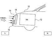
- FIG. 1 is a schematic diagram showing a configuration of a vehicle 10 to which an air purification device of an embodiment is applied.
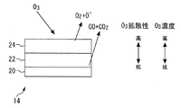
- 2 is a cross-sectional view of a core portion of a radiator 14.
- FIG. It is data which shows the result of an ozone purification endurance test. It is the figure which showed the relationship between the wind speed of the gas which passes a radiator, and a gas contact probability. It is a prediction figure of the time-dependent change of the ozone purification rate of the ozone purification body which used the organometallic complex together with activated carbon. It is a figure which shows the internal structure of the activated carbon which carried the organic metal complex by dispersion
- FIG. 1 is a schematic diagram showing a configuration of a vehicle equipped with the air purification device of the present embodiment.
- the vehicle 10 includes an internal combustion engine 12 as a power unit.
- the exhaust gas discharged from the internal combustion engine 12 contains HC and NOx.
- Ozone is generated by a photochemical reaction using HC or NOx as a reactant. Therefore, by mounting an air purification device on the vehicle 10 including the internal combustion engine 12 and purifying ozone in the air while the vehicle 10 is traveling, the influence of the vehicle 10 on the environment can be reduced.
- a radiator 14 that cools cooling water to be circulated through the internal combustion engine 12 is disposed in front of the internal combustion engine 12.
- a condenser 16 for an air conditioner is attached in front of the radiator 14. As indicated by arrows in FIG. 1, when the vehicle 10 travels, air is taken in from the bumper grille 18 on the front surface of the vehicle 10, and the taken-in air passes through the condenser 16 and the radiator 14 in this order and is discharged backward. Is done.
- FIG. 2 is a cross-sectional view of the core portion of the radiator 14.
- the core portion of the radiator 14 includes fins 20, an activated carbon layer 22, and an ozone purification catalyst layer 24.
- the fin 20 is comprised from the aluminum alloy etc. which are excellent in heat conductivity.
- the activated carbon layer 22 is composed of activated carbon and a binder A for bonding the fins 20 and the activated carbon.
- the ozone purification catalyst layer 24 includes an organometallic complex having manganese, iron, cobalt, nickel, copper, ruthenium, rhodium or palladium as a central metal, and a binder B for bonding the activated carbon layer 22 and the organometallic complex. It is composed of
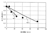
- FIG. 3 is data showing the results of an ozone purification endurance test.
- the horizontal axis in FIG. 3 represents the endurance distance (kilomile), and the vertical axis represents the relative value based on the ozone purification rate in the initial state (when the endurance distance is 0 kilomile).
- Each data shown in FIG. 3 is prepared by preparing two activated carbons having the same size and specific surface area, and moving ozone-containing gas having a constant concentration from the front to the rear of the two activated carbons at different speeds (wind speed 1 m / s and wind speed). 10 m / s), and obtained by measuring the ozone concentration behind the activated carbon, respectively.
- the ozone purification rate of the activated carbon decreases as the endurance distance increases. Further, as shown in FIG. 3, the degree of decrease in the ozone purification rate of the activated carbon varies depending on the wind speed of the ozone-containing gas to be passed. Specifically, when the ozone-containing gas is passed at a wind speed of 1 m / s, the ozone purification rate is reduced to about half of the initial state at about 30 km, but when the ozone-containing gas is passed at a wind speed of 10 m / s. Even about 30 km, it shows about 70% or more of the initial state, and finally decreases to about half of the initial state around 60 km. That is, the degree of decrease in the ozone purification rate is smaller when passing at a high speed (wind speed of 10 m / s) than when passing at a low speed (wind speed of 1 m / s).
- FIG. 4 is a graph showing the relationship between the wind speed of the gas passing through the radiator and the probability that the gas contacts the radiator (hereinafter referred to as “gas contact probability”). This graph was calculated by applying the Gormley-Kennedy diffusion theory formula to the aluminum honeycomb radiator model. As shown in FIG. 4, the gas contact probability is about 100% when the wind speed is around 1 m / s, and the gas contact probability is about 10% when the wind speed is around 10 m / s. That is, the gas contact probability is high when the wind speed is low, and gradually decreases as the wind speed increases.
- the present inventors speculate that the above-described correlation between the ozone purification rate of activated carbon and the gas contact probability is due to the ozonolysis mechanism of activated carbon and the aging of the internal structure of the activated carbon.
- the ozonolysis mechanism of activated carbon will be described.
- Activated carbon has countless pores formed from the surface to the inside. When ozone molecules enter the pores, electrons are donated from the activated carbon, resulting in a decrease in the activation energy of the ozone decomposition reaction. , Ozone is converted to oxygen and active oxygen.
- the ozonolysis reaction of activated carbon is specifically expressed as a reaction of the following formulas (1) and (2). O 3 ⁇ O 3 - ⁇ ( 1) O 3 ⁇ ⁇ O 2 + O ⁇ (2)
- Active oxygen (O ⁇ ) generated by the ozonolysis reaction of activated carbon acts as an oxidizing agent for activated carbon. Since this active oxygen has a strong oxidizing power, when the active oxygen enters the pores of the activated carbon, the activated carbon is oxidized. Therefore, the ozone purification function of activated carbon may be lost.
- the oxidation reaction of activated carbon with active oxygen is specifically expressed as a reaction of the following formulas (3) and (4).
- the organometallic complex has an ozone purifying function like activated carbon.
- the ozonolysis reaction of the organometallic complex is specifically expressed as a reaction of the following formulas (5) and (6).
- O 3 ⁇ O 3 - ⁇ ( 5) O 3 ⁇ ⁇ O 2 + O ⁇ (6)
- the reactions of the above formulas (5) and (6) are reactions that proceed on the central metal of the organometallic complex, and are the same reactions as the above formulas (1) and (2). Therefore, if the organometallic complex is used in combination with activated carbon, it is considered that the gas contact probability to the activated carbon can be relatively lowered.
- the organometallic complex can convert active oxygen generated by the ozonolysis reaction of activated carbon into oxygen.
- the conversion reaction of active oxygen by the organometallic complex is specifically expressed as a reaction of the following formula (7).
- O ⁇ + O 3 ⁇ ⁇ 2O 2 (7) The reaction of the above formula (7) is a reaction that proceeds on the central metal of the organometallic complex as in the above formulas (5) and (6).
- O 3 ⁇ and O ⁇ generated by the reactions of the above formulas (1) and (2) can be used. Therefore, it is considered that if the organometallic complex is used in combination with activated carbon, the oxidation reaction of activated carbon by the active oxygen (reactions of the above formulas (3) and (4)) can be suppressed.
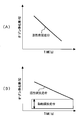
- FIG. 5 is a prediction diagram of the change over time in the ozone purification rate of an ozone purifier using an organometallic complex in combination with activated carbon.
- the organometallic complex when used in combination with activated carbon, the gas contact probability to activated carbon can be relatively lowered, and the oxidation reaction of activated carbon by active oxygen can be suppressed. Therefore, as shown in FIG. 5, the case where the cocatalyst (that is, the organometallic complex) is used in combination with activated carbon (FIG. 5B) is compared to the case where the activated carbon is used alone (FIG. 5A). Therefore, it can be predicted that the lifetime of the ozone purifier will be extended.
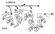
- FIG. 6 is a diagram showing the internal structure of activated carbon on which an organometallic complex is dispersed and supported. As indicated by arrows in FIG. 6, ozone molecules flow on the surface of the ozone purifier, and at that time, enter the pores of the activated carbon or coordinate on the central metal of the organometallic complex.
- the desorption phenomenon may occur in which ozone molecules that have entered the pores are scraped out before the purification or are peeled off from the organometallic complex.
- the wind speed is high, the possibility of such a desorption phenomenon is reduced.
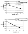
- FIG. 7 is data showing the results of an ozone purification endurance test.
- the horizontal axis in FIG. 7 represents the endurance distance (kilomile), and the vertical axis represents the relative value based on the ozone purification rate in the initial state (when the endurance distance is 0 kilomile).
- the data shown in FIG. 7 shows that two activated carbons on which a picket fence type porphyrin complex (center metal is iron) is dispersed and supported (size and specific surface area are the same), and the two activated carbons are directed from the front to the rear.
- ozone-containing gas with a constant concentration is passed at different speeds (wind speed 1 m / s and wind speed 10 m / s), it is obtained by measuring the ozone concentration behind the activated carbon.
- FIG. 7 shows the data of FIG. 3 for comparison with the data in addition to the data of the activated carbon on which the complex is dispersed and supported.
- the data in FIG. 3 is shown as a relative value based on the ozone purification rate in the initial state of the activated carbon on which the complex is dispersed and supported.
- FIG. 7A shows data when passing at a wind speed of 1 m / s
- FIG. 7B shows data when passing at a wind speed of 10 m / s.
- FIG. 7 (A) it is understood that the activated carbon on which the complex is dispersed and supported suppresses the decrease in the ozone purification rate as compared with the activated carbon of FIG.
- FIG. 7 (A) confirms that ozone molecules not only entered the pores of the activated carbon but also coordinated with the organometallic complex and were purified without desorption. I can say that.
- FIG. 7B it can be seen that the degree of decrease in the ozone purification rate of the activated carbon in which the complex is dispersed and supported is substantially equal to that of the activated carbon of FIG.
- the data in FIG. 7 (A) supports that ozone molecules coordinated to the organometallic complex were desorbed before purification, while ozone molecules that had entered the pores of the activated carbon were quickly purified. It can be said that there is.
- the ozone purification catalyst layer 24 uses the binder B having a larger specific surface area than the binder A constituting the activated carbon layer 22.
- gas diffusivity is increased inside a substance having a large specific surface area. Therefore, if the binder B having a specific surface area larger than that of the binder A is used for the ozone purification catalyst layer 24, the probability that the atmosphere contacts the organometallic complex in the ozone purification catalyst layer 24 can be increased. Therefore, since an environment where the wind speed is slow can be created, it is possible to suppress the desorption of ozone molecules from the organometallic complex before purification.
- the diffusibility of gas is reduced inside a substance having a small specific surface area. Therefore, if the binder A having a specific surface area smaller than that of the binder B is used for the activated carbon layer 22, the probability that the atmosphere contacts the activated carbon in the activated carbon layer 22 can be reduced. As described in the description of FIGS. 3 and 4, if the gas contact probability is low, the degree of decrease in the ozone purification rate of the activated carbon is small. Therefore, in the activated carbon layer 22, an environment in which the wind speed is increased can be created, so that the degree of decrease in the ozone purification rate of the activated carbon can be reduced.
- the present embodiment it is possible to suppress the desorption of ozone molecules from the organometallic complex in the ozone purification catalyst layer 24 and to reduce the degree of decrease in the ozone purification rate of the activated carbon in the activated carbon layer 22. Therefore, the lifetime of the ozone purifier can be extended while effectively utilizing the ozone purifying function of the organometallic complex.
- the binder A was used for the activated carbon layer 22 and the binder B was used for the ozone purification catalyst layer 24, respectively, the binder A may be partially used for the ozone purification catalyst layer 24, A part of the binder B may be used for the activated carbon layer 22.
- two types of binders A and B having different specific surface areas are used, but two or more types of binders may be used. That is, as long as the probability that the atmosphere contacts the organometallic complex of the ozone purification catalyst layer 24 can be increased and the probability that the atmosphere contacts the activated carbon of the activated carbon layer 22 can be decreased, the selection of the binder can be variously modified.
- the ozone purifier is composed of two layers of the activated carbon layer 22 and the ozone purifying catalyst layer 24, but may be composed of two or more layers.
- a three-layer configuration in which an intermediate layer in which activated carbon and an ozone purification catalyst are mixed is provided between the activated carbon layer 22 and the ozone purification catalyst layer 24 may be employed. That is, as long as the probability that the atmosphere contacts the organometallic complex of the ozone purification catalyst layer 24 can be increased and the probability that the atmosphere contacts the activated carbon of the activated carbon layer 22 can be decreased, the layer structure of the ozone purifier can be variously modified. .
- an organometallic complex is used for the ozone purification catalyst layer 24.
- a metal complex may be coated instead of the organometallic complex, or palladium, silver, platinum or gold, or zeolite May be coated. These substitute materials have an ozone purifying function and resistance to the active oxygen as in the case of the organometallic complex.
- the metal complex that can be used as an alternative include those having the central metal as listed as the central metal of the organometallic complex. Two or more of these alternative materials may be used at the same time, or may be used with an organometallic complex.
Landscapes
- Engineering & Computer Science (AREA)
- Chemical & Material Sciences (AREA)
- General Engineering & Computer Science (AREA)
- Mechanical Engineering (AREA)
- Combustion & Propulsion (AREA)
- Health & Medical Sciences (AREA)
- Chemical Kinetics & Catalysis (AREA)
- Environmental & Geological Engineering (AREA)
- Analytical Chemistry (AREA)
- Oil, Petroleum & Natural Gas (AREA)
- General Chemical & Material Sciences (AREA)
- Biomedical Technology (AREA)
- Epidemiology (AREA)
- Life Sciences & Earth Sciences (AREA)
- Animal Behavior & Ethology (AREA)
- General Health & Medical Sciences (AREA)
- Public Health (AREA)
- Veterinary Medicine (AREA)
- Catalysts (AREA)
- Exhaust Gas Treatment By Means Of Catalyst (AREA)
Abstract
Description
車両の走行時に大気の流路が形成される箇所に配置された車両構成部品と、
前記車両構成部品の表面に形成され、オゾンを浄化可能なオゾン浄化触媒と、活性炭とを含むオゾン浄化体と、を備え、
前記オゾン浄化触媒の前記活性炭に対する体積割合を担持割合と定義した場合に、前記オゾン浄化体の大気接触面側における前記担持割合が、前記オゾン浄化体の車両構成部品接触面側における前記担持割合よりも大きくなるように調整したことを特徴とする。
前記オゾン浄化体は、比表面積の異なる複数のバインダーを更に含み、
前記オゾン浄化体の大気接触面側に、前記オゾン浄化体の車両構成部品接触面側よりも比表面積の大きいバインダーを使用したことを特徴とする。
前記オゾン浄化体は、大気接触面層と車両構成部品接触面層とから構成され、
前記大気接触面層に前記オゾン浄化触媒と第1のバインダーを使用し、前記車両構成部品接触面層に前記活性炭と前記第1のバインダーよりも比表面積の小さい第2のバインダーとを使用したことを特徴とする。
以下、図1乃至図7を参照しながら、本発明の実施の形態について説明する。図1は、本実施の形態の大気浄化装置を搭載した車両の構成を示す概略図である。車両10は、動力装置としての内燃機関12を備えている。内燃機関12から排出される排気ガスには、HCやNOxが含まれている。オゾンはHCやNOxを反応物として光化学反応により生成される。そのため、内燃機関12を備える車両10に大気浄化装置を搭載し、車両10の走行中に大気中のオゾンを浄化することで、車両10が環境に与える影響を低減することができる。
図3は、オゾン浄化耐久試験の結果を示すデータである。図3の横軸は耐久距離(キロマイル)を、縦軸は初期状態(耐久距離0キロマイル時)におけるオゾン浄化率を基準とした相対値を、それぞれ示す。図3中に示す各データは、サイズおよび比表面積が同等の2つの活性炭を準備し、この2つの活性炭の前方から後方に向けて一定濃度のオゾン含有ガスを異なる速度(風速1m/sおよび風速10m/s)で通過させた際に、活性炭後方のオゾン濃度をそれぞれ測定することにより得たものである。
O3→O3 - ・・・(1)
O3 -→O2+O- ・・・(2)
C+O→CO ・・・(3)
C+2O→CO2 ・・・(4)
O3→O3 - ・・・(5)
O3 -→O2+O- ・・・(6)
上記式(5)、(6)の反応は、有機金属錯体の中心金属上で進行する反応であり、上記式(1)、(2)と同一の反応である。従って、上記有機金属錯体を活性炭と併用すれば、活性炭へのガス接触確率を相対的に低下できると考えられる。
O-+O3 -→2O2 ・・・(7)
上記式(7)の反応は、上記式(5)、(6)同様、有機金属錯体の中心金属上で進行する反応である。この反応は、上記式(5)、(6)の反応のみならず上記式(1)、(2)の反応により生じたO3 -やO-を利用できる。従って、上記有機金属錯体を活性炭と併用すれば、活性酸素による活性炭の酸化反応(上記式(3)、式(4)の反応)を抑制できるとも考えられる。
12 内燃機関
14 ラジエータ
16 コンデンサ
18 バンパーグリル
20 フィン
22 活性炭層(車両構成部品接触面層)
24 オゾン浄化触媒層(大気接触面層)
Claims (3)
- 車両の走行時に大気の流路が形成される箇所に配置された車両構成部品と、
前記車両構成部品の表面に形成され、オゾンを浄化可能なオゾン浄化触媒と、活性炭とを含むオゾン浄化体と、を備え、
前記オゾン浄化触媒の前記活性炭に対する体積割合を担持割合と定義した場合に、前記オゾン浄化体の大気接触面側における前記担持割合が、前記オゾン浄化体の車両構成部品接触面側における前記担持割合よりも大きくなるように調整したことを特徴とする車両用大気浄化装置。 - 前記オゾン浄化体は、比表面積の異なる複数のバインダーを更に含み、
前記オゾン浄化体の大気接触面側に、前記オゾン浄化体の車両構成部品接触面側よりも比表面積の大きいバインダーを使用したことを特徴とする請求項1に記載の車両用大気浄化装置。 - 前記オゾン浄化体は、大気接触面層と車両構成部品接触面層とから構成され、
前記大気接触面層に前記オゾン浄化触媒と第1のバインダーを使用し、前記車両構成部品接触面層に前記活性炭と前記第1のバインダーよりも比表面積の小さい第2のバインダーとを使用したことを特徴とする請求項1または2に記載の車両用大気浄化装置。
Priority Applications (4)
| Application Number | Priority Date | Filing Date | Title |
|---|---|---|---|
| PCT/JP2011/058192 WO2012131968A1 (ja) | 2011-03-31 | 2011-03-31 | 車両用大気浄化装置 |
| JP2013506978A JP5617997B2 (ja) | 2011-03-31 | 2011-03-31 | 車両用大気浄化装置 |
| US14/004,441 US9486549B2 (en) | 2011-03-31 | 2011-03-31 | Air cleaner for vehicle |
| DE112011105108.5T DE112011105108B4 (de) | 2011-03-31 | 2011-03-31 | Luftfilter für Fahrzeug |
Applications Claiming Priority (1)
| Application Number | Priority Date | Filing Date | Title |
|---|---|---|---|
| PCT/JP2011/058192 WO2012131968A1 (ja) | 2011-03-31 | 2011-03-31 | 車両用大気浄化装置 |
Publications (1)
| Publication Number | Publication Date |
|---|---|
| WO2012131968A1 true WO2012131968A1 (ja) | 2012-10-04 |
Family
ID=46929790
Family Applications (1)
| Application Number | Title | Priority Date | Filing Date |
|---|---|---|---|
| PCT/JP2011/058192 Ceased WO2012131968A1 (ja) | 2011-03-31 | 2011-03-31 | 車両用大気浄化装置 |
Country Status (4)
| Country | Link |
|---|---|
| US (1) | US9486549B2 (ja) |
| JP (1) | JP5617997B2 (ja) |
| DE (1) | DE112011105108B4 (ja) |
| WO (1) | WO2012131968A1 (ja) |
Cited By (2)
| Publication number | Priority date | Publication date | Assignee | Title |
|---|---|---|---|---|
| JP2015085308A (ja) * | 2013-11-01 | 2015-05-07 | トヨタ自動車株式会社 | 車両用大気浄化装置 |
| CN106813307A (zh) * | 2015-12-01 | 2017-06-09 | 天津市爱德恒业科技发展有限公司 | 一种简易型空气净化器 |
Families Citing this family (4)
| Publication number | Priority date | Publication date | Assignee | Title |
|---|---|---|---|---|
| US11090602B2 (en) | 2015-03-13 | 2021-08-17 | Donaldson Company, Inc. | Activated carbon and catalyst filter |
| US9493356B1 (en) * | 2015-07-17 | 2016-11-15 | The United States Of America As Represented By The Secretary Of The Navy | Impregnation of macrocycle organics to activated carbon |
| CN106813309A (zh) * | 2015-12-01 | 2017-06-09 | 天津市爱德恒业科技发展有限公司 | 一种新型的家用空气净化器 |
| US11369913B2 (en) | 2019-04-30 | 2022-06-28 | Nasik Elahi | Air pollution remediation system for large open-air spaces |
Citations (2)
| Publication number | Priority date | Publication date | Assignee | Title |
|---|---|---|---|---|
| JPH04131126A (ja) * | 1990-09-21 | 1992-05-01 | Toshiba Corp | 排オゾン処理装置 |
| JP2010029816A (ja) * | 2008-07-30 | 2010-02-12 | Toyota Motor Corp | 大気浄化装置 |
Family Cites Families (4)
| Publication number | Priority date | Publication date | Assignee | Title |
|---|---|---|---|---|
| US5212140A (en) * | 1991-02-28 | 1993-05-18 | Sakai Chemical Industry Co., Inc. | Catalyst for decomposing ozone |
| AU4701196A (en) | 1995-01-20 | 1996-08-07 | Engelhard Corporation | Pollutant treating device located in vehicle compartment for cleaning ambient air |
| JPWO2012127643A1 (ja) | 2011-03-23 | 2014-07-24 | トヨタ自動車株式会社 | 車両用大気浄化装置 |
| BR112013023823B1 (pt) | 2011-03-23 | 2020-12-29 | Toyota Jidosha Kabushiki Kaisha | limpador de ar para veículos |
-
2011
- 2011-03-31 WO PCT/JP2011/058192 patent/WO2012131968A1/ja not_active Ceased
- 2011-03-31 DE DE112011105108.5T patent/DE112011105108B4/de not_active Expired - Fee Related
- 2011-03-31 JP JP2013506978A patent/JP5617997B2/ja not_active Expired - Fee Related
- 2011-03-31 US US14/004,441 patent/US9486549B2/en not_active Expired - Fee Related
Patent Citations (2)
| Publication number | Priority date | Publication date | Assignee | Title |
|---|---|---|---|---|
| JPH04131126A (ja) * | 1990-09-21 | 1992-05-01 | Toshiba Corp | 排オゾン処理装置 |
| JP2010029816A (ja) * | 2008-07-30 | 2010-02-12 | Toyota Motor Corp | 大気浄化装置 |
Cited By (2)
| Publication number | Priority date | Publication date | Assignee | Title |
|---|---|---|---|---|
| JP2015085308A (ja) * | 2013-11-01 | 2015-05-07 | トヨタ自動車株式会社 | 車両用大気浄化装置 |
| CN106813307A (zh) * | 2015-12-01 | 2017-06-09 | 天津市爱德恒业科技发展有限公司 | 一种简易型空气净化器 |
Also Published As
| Publication number | Publication date |
|---|---|
| JPWO2012131968A1 (ja) | 2014-07-24 |
| US20140010714A1 (en) | 2014-01-09 |
| JP5617997B2 (ja) | 2014-11-05 |
| US9486549B2 (en) | 2016-11-08 |
| DE112011105108T5 (de) | 2014-01-23 |
| DE112011105108B4 (de) | 2019-12-05 |
Similar Documents
| Publication | Publication Date | Title |
|---|---|---|
| JP5617997B2 (ja) | 車両用大気浄化装置 | |
| JP5725157B2 (ja) | 車両用大気浄化装置 | |
| JP5672373B2 (ja) | 車両用大気浄化装置 | |
| CN114768793B (zh) | 用于污染控制的催化剂涂层 | |
| JP5387766B2 (ja) | 車両用大気浄化装置 | |
| KR20040026139A (ko) | 대기중 오염물질을 처리하는 방법 | |
| WO2012127643A1 (ja) | 車両用大気浄化装置 | |
| JP5657111B2 (ja) | 車両用大気浄化装置およびその製造方法 | |
| JP2014024027A (ja) | 車両用大気浄化装置 | |
| JP5884809B2 (ja) | 車両用大気浄化装置 | |
| US9162003B2 (en) | Air purification device for vehicle | |
| JP5264316B2 (ja) | リーンバーン自動車排ガス浄化用触媒 | |
| JP2007237134A (ja) | 排ガス浄化方法 | |
| JP2011220115A (ja) | 内燃機関の排気浄化装置 | |
| JP2012180787A (ja) | 排ガス浄化装置 | |
| JPH06126178A (ja) | 窒素酸化物浄化用触媒 |
Legal Events
| Date | Code | Title | Description |
|---|---|---|---|
| 121 | Ep: the epo has been informed by wipo that ep was designated in this application |
Ref document number: 11862227 Country of ref document: EP Kind code of ref document: A1 |
|
| ENP | Entry into the national phase |
Ref document number: 2013506978 Country of ref document: JP Kind code of ref document: A |
|
| WWE | Wipo information: entry into national phase |
Ref document number: 14004441 Country of ref document: US |
|
| WWE | Wipo information: entry into national phase |
Ref document number: 112011105108 Country of ref document: DE Ref document number: 1120111051085 Country of ref document: DE |
|
| 122 | Ep: pct application non-entry in european phase |
Ref document number: 11862227 Country of ref document: EP Kind code of ref document: A1 |