WO2012131960A1 - 通信装置、経路探索方法および経路探索プログラム - Google Patents
通信装置、経路探索方法および経路探索プログラム Download PDFInfo
- Publication number
- WO2012131960A1 WO2012131960A1 PCT/JP2011/058138 JP2011058138W WO2012131960A1 WO 2012131960 A1 WO2012131960 A1 WO 2012131960A1 JP 2011058138 W JP2011058138 W JP 2011058138W WO 2012131960 A1 WO2012131960 A1 WO 2012131960A1
- Authority
- WO
- WIPO (PCT)
- Prior art keywords
- route search
- search request
- adjacent communication
- transmission
- unit
- Prior art date
- Legal status (The legal status is an assumption and is not a legal conclusion. Google has not performed a legal analysis and makes no representation as to the accuracy of the status listed.)
- Ceased
Links
Images








Classifications
-
- H—ELECTRICITY
- H04—ELECTRIC COMMUNICATION TECHNIQUE
- H04L—TRANSMISSION OF DIGITAL INFORMATION, e.g. TELEGRAPHIC COMMUNICATION
- H04L45/00—Routing or path finding of packets in data switching networks
- H04L45/26—Route discovery packet
-
- H—ELECTRICITY
- H04—ELECTRIC COMMUNICATION TECHNIQUE
- H04L—TRANSMISSION OF DIGITAL INFORMATION, e.g. TELEGRAPHIC COMMUNICATION
- H04L47/00—Traffic control in data switching networks
- H04L47/10—Flow control; Congestion control
- H04L47/12—Avoiding congestion; Recovering from congestion
Definitions
- the present invention relates to a communication device, a route search method, and a route search program.
- An autonomous decentralized network connects a large number of terminals to each other without an access point using a technology used for wireless connection such as a computer, a PDA (Personal Digital Assistant), and a mobile phone terminal.
- the autonomous distributed network autonomously performs network construction that accompanies the addition or deletion of nodes, so it can reduce the labor of network settings, and when there are many nodes or the network configuration changes at a certain frequency It is effective for.
- the management server or each node when the management server or each node detects the occurrence of an event, it first transmits a packet to each node in the network and receives a response. Next, the management server and each node generate a topology from the received response. Thereafter, the management server and each node detect a change in the network configuration by comparing the topology generated when the previous event was detected with the topology generated this time.
- the management server and each node execute many processes to identify a change in the network configuration, and the processing load becomes large in a large-scale network with a large number of nodes. Further, in a large-scale network, a huge number of nodes are transmitted, so the amount of traffic is enormous. Furthermore, when a node is frequently added or deleted, the processing load becomes a bottleneck, and there is a problem that it cannot follow the change in the network configuration.
- the technology disclosed in the specification and drawings has been made in view of the above, and an object thereof is to provide a communication device, a route search method, and a route search program capable of confirming a network configuration with less traffic.
- the communication device, route search method, and route search program disclosed in the present application include, in one aspect, a transmission unit, a reception unit, a transmission execution unit, a transmission stop unit, and a warning transmission unit.
- the transmission unit transmits the route search to an adjacent communication device that is not selected as a transmission destination of a route search request for requesting a route search from the own device to a predetermined device among adjacent communication devices that are communication devices capable of direct communication. Send a request.
- the reception unit receives a response to the route search request transmitted from the transmission unit from the predetermined device.
- the transmission execution unit receives the response, and when the number of adjacent communication devices whose routes are confirmed is less than a predetermined number and there is an unselected adjacent communication device, the transmission unit performs the route search.
- the transmission stop unit stops the transmission of the route search request executed by the transmission unit when the number of adjacent communication devices whose paths are confirmed and the response is received reaches a predetermined number.
- the warning transmission unit transmits a warning to the predetermined device when the number of adjacent communication devices whose paths have been confirmed is less than a predetermined number and there is no adjacent communication device that is not selected.
- route search method, and route search program disclosed in the present application there is an effect that the network configuration can be confirmed with less traffic.
- FIG. 1 is a diagram illustrating an overall configuration of a system according to the first embodiment.
- FIG. 2 is a functional block diagram showing the configuration of the node device.
- FIG. 3 is a diagram illustrating an example of information stored in the redundant path table.
- FIG. 4 is a diagram illustrating an example of information stored in the link table.
- FIG. 5 is a diagram illustrating an example of information stored in the routing table.
- FIG. 6 is a diagram illustrating an example of information stored in the transfer record table.
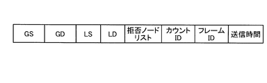
- FIG. 7 is a diagram illustrating a frame format example of a route search request.
- FIG. 8 is a diagram showing a warning frame format.
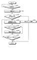
- FIG. 9 is a flowchart illustrating a process flow when the node device according to the first embodiment transmits a route search request.
- FIG. 9 is a flowchart illustrating a process flow when the node device according to the first embodiment transmits a route search request.
- FIG. 9 is a flowchart illustrating a process flow
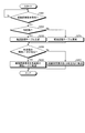
- FIG. 10 is a flowchart illustrating a process flow when the node device according to the first embodiment receives a route search request.
- FIG. 11 is a diagram illustrating an overall configuration of a system according to the second embodiment.
- FIG. 12 is a diagram illustrating an example of a frame format for a route search request.
- FIG. 13 is a flowchart illustrating a process flow when the node device according to the second embodiment transmits a route search request when the link is disconnected.
- FIG. 14 is a flowchart illustrating a process flow when the node device according to the second embodiment receives a route search request.
- FIG. 15 is a diagram illustrating a hardware configuration example of a computer that executes a redundant route search program.
- the node device described here is a device such as a communication device that forms an ad hoc network, such as an information processing device such as a server, a relay device such as a router, or a wireless device including a sensor.
- FIG. 1 is a diagram illustrating an overall configuration of a system according to the first embodiment.
- this system includes a GW (gateway) device 5, a management server 7, a node device A, a node device B, a node device C, a node device D, a node device E, a node device F, a node device G, A node device H is included.
- the system shown in FIG. 1 is an autonomous decentralized network such as an ad hoc network, and each node device is connected to each other without an access point using a technique used for wireless connection.
- the node device illustrated in FIG. 1 is an example of a communication device.
- the GW device 5 is a data relay device that executes data relay between the system shown in FIG. 1 and another system, data relay between each node device and the management server 7 shown in FIG.
- the GW apparatus 5 transfers each information transmitted from each node apparatus to the management server 7.
- the management server 7 is a computer device used by an administrator who manages the system and each node device shown in FIG. 1, and receives information transmitted from each node device via the GW device 5.
- Each node device is a computer device constituting an ad hoc network, and is a device capable of wireless connection such as a PDA (Personal Digital Assistant) or a mobile phone terminal.
- each node device can identify a node device that can communicate, in other words, an adjacent node device, and a route to the GW device 5 by exchanging Hello packets between the nodes.
- Each such node device is an adjacent node device that is not selected as a destination of a route search request for requesting a route search from the own device to the GW device 5 among adjacent node devices that are direct communication devices.
- Each node device transmits a route search request when a response is received, the number of adjacent node devices whose routes have been confirmed is less than a predetermined number, and there are unselected adjacent communication devices.
- each node device stops transmitting a route search request when the response is received and the number of adjacent node devices whose routes are confirmed reaches a predetermined number.
- each node device when the number of adjacent node devices whose routes have been confirmed is less than a predetermined number and there is no communicable adjacent node communication device to which a route search request has not been transmitted exists, to the GW device 5 Send a warning.
- each node device stops the route search when a predetermined number of redundant routes can be secured, and transmits a warning to the GW device 5 when the predetermined number of redundant routes cannot be secured.
- FIG. 2 is a functional block diagram showing the configuration of the node device. Since each node device shown in FIG. 1 has the same configuration, the node device 10 will be described here. Further, the GW device 5 has the same configuration as a general gateway device, and the management server 7 has the same configuration as a general server device, so detailed description thereof will be omitted here.
- the node device 10 includes a wireless interface unit 11, a storage unit 12, a wireless processing unit 13, a search execution unit 14, and a search response unit 15.
- each control part illustrated here is an illustration to the last, and is not limited to this, For example, you may have display parts, such as a display, and input parts, such as a keypad.
- the storage unit 12 is a storage device such as a semiconductor memory element or a hard disk.
- the wireless processing unit 13, the search execution unit 14, and the search response unit 15 are, for example, an electronic circuit such as a CPU (Central Processing Unit) or an integrated circuit such as an FPGA (Field-Programmable Gate Array).
- the wireless interface unit 11 has at least one antenna, transmits and receives radio waves via the antenna, and establishes wireless communication with each node device. For example, the wireless interface unit 11 transmits a route search request to the adjacent node device and receives a route search request response from the GW device 5. In addition, the wireless interface unit 11 transmits a warning to the GW device 5.
- the storage unit 12 stores various types of information used for wireless communication, and includes a redundant path table 12a, a link table 12b, a routing table 12c, and a transfer record table 12d. In addition, the storage unit 12 stores “2” as “the number of redundant paths specified by the user” as SLA (Service Level Agreement).
- SLA Service Level Agreement
- the redundant route table 12a stores a redundant route whose route has been confirmed.
- the information stored here is stored by the search execution unit 14 or the like.
- “2” redundant paths stored as SLA are stored as maximum values.
- FIG. 3 is a diagram showing an example of information stored in the redundant route table.
- the redundant path table 12a stores “adjacent node, address information”.
- the “adjacent node” stored here indicates a node device capable of wireless communication that reaches the node device 10 first as a route to the GW device 5, and “address information” is a neighbor such as a MAC address (Media Access Control), for example. This is node device address information.
- “node B” whose MAC address is MAC (B)
- “node E” whose MAC address is MAC (E) are stored as redundant paths of the node device 10.
- the link table 12b stores information on node devices capable of wireless communication with the node device 10.
- the information stored here is stored based on Hello packets exchanged with other node devices by the wireless processing unit 13 or the like described later, or stored by an administrator or the like.
- FIG. 4 is a diagram showing an example of information stored in the link table.
- the link table 12b stores “adjacent node, address information”.
- the “adjacent node” stored here indicates a node device capable of wireless communication with the node device 10, and the “address information” is address information of the adjacent node device such as a MAC address.
- “Node B, Node C, Node E, Node G, and Node H” are stored as adjacent nodes, and each MAC address is “MAC (B), MAC (C), MAC (E), MAC”. (G), MAC (H) ".
- the routing table 12c stores a route having a high priority among the routes from the node device 10 to the GW device 5, that is, a call quality. Note that the information stored here is stored based on Hello packets exchanged with other node devices by the wireless processing unit 13 or the like described later, or stored by an administrator or the like.
- FIG. 5 is a diagram showing an example of information stored in the routing table.
- the routing table 12 c stores “GD (Global Destination) address information, LD (Local Destination) address information, priority”.
- the “GD address information” stored here is the address information of the node that is the final destination, and here, the MAC address of the GW apparatus 5 is stored.
- “LD address information” stores the address information of the next destination node as viewed from the node device 10 with respect to the GD, that is, the MAC address of the adjacent node of the node device 10 when the GW device 5 is the destination. Is done.
- the “priority” is information indicating a descending order of call quality. For example, 1 is the highest and 3 is the third.
- the route from the node device 10 to the MAC (B) has the highest priority in the route destined to the MAC (GW), and then the route priority from the node device 10 to the MAC (C) This indicates that the priority of the route from the node device 10 to the MAC (G) is the third.
- the transfer record table 12d is a temporary storage area for storing information at the time of redundant route search for each redundant route search request. Note that the information stored here is stored by a search execution unit 14 and a search response unit 15 described later, or stored by an administrator or the like.
- FIG. 6 is a diagram illustrating an example of information stored in the transfer record table. As shown in FIG. 6, the transfer record table 12d stores “GS (Global Source), count ID, destination candidate, flag, adjacent node, flag, LS (Local Source)”. The transfer record table 12d stores the above information for each route search request, that is, for each frame ID described later.
- “GS” stored here is the MAC address of the source node device that transmitted the route search request, and “Count ID” is information indicating the number of redundant routes to be searched for the route search request. It is. “Destination candidate” is the MAC address of the adjacent node acquired from the routing table 12c of the node device 10, and “Flag” is information indicating whether or not a route search request has been transmitted to each destination candidate. . “Neighboring node” is the MAC address of the neighboring node acquired from the link table 12b of the node device 10, and “flag” is information indicating whether or not a route search request has been transmitted to each neighboring node. . “LS” indicates a transfer source of the redundant route search request.
- FIG. 6 it shows that a route search request for searching for the “first” redundant route is received from the node device E which is “MAC (E)”.
- the candidate of the adjacent node device having a high priority is “MAC (B), MAC (C), MAC (G)”, which indicates that the route search request has already been transmitted to MAC (B).
- the node device adjacent to the node device 10 is “MAC (B), MAC (C), MAC (E), MAC (G), MAC (H)”, and the route search request has already been made to MAC (B). Indicates that has been sent.
- the wireless processing unit 13 is a processing unit that executes wireless communication related to a general ad hoc network. For example, the wireless processing unit 13 establishes wireless communication between the node device 10 and another node device. Further, the wireless processing unit 13 transmits / receives a Hello packet to / from another node device, and specifies a route to the GW device 5. Then, the wireless processing unit 13 generates data of the redundant route table 12a. Similarly, the wireless processing unit 13 transmits / receives Hello packets to / from other node devices, specifies adjacent node devices, and generates data of the link table 12b and the routing table 12c.
- the search execution unit 14 includes a transmission unit 14a, a reception unit 14b, a count unit 14c, a transmission control unit 14d, and a warning transmission unit 14e. With these, the route search is performed at a predetermined trigger such as when the node device 10 is activated. A processing unit to be executed.
- the transmitting unit 14a transmits a route search request to a node device that has not yet transmitted a route search request for requesting a route search from the node device 10 to the GW device 5 among the node devices capable of direct communication.
- the transmission unit 14 a refers to the routing table 12 c, and the MAC (which is address information of the adjacent node (B) having the highest priority. B) is acquired. Then, the transmission unit 14a transmits a route search request to the MAC (B).
- a route search request to be transmitted will be described.
- FIG. 7 is a diagram illustrating a frame format example of a route search request.
- this route search request is formed of “GS, GD, LS, LD, reject node list, count ID, frame ID, transmission time”.
- “GS” is address information of the source node device, and in this example, is the MAC address of the node device 10.
- GD is address information of the final destination of the route search request, and in this example, is address information “MAC (GW)” of the GW device.
- “LS” is the address information of the node device that has transferred the route search request, and in this example, is the MAC address of the node device 10.
- “LS” is the MAC address of the node device E.
- “LD” is address information of a node device that is a transmission destination of a route search request, and is MAC (B) in this example.
- the “rejected node list” is address information of a node device that cannot be specified as a transfer destination of a route search request, and is address information of a node indicated in the link table of “GS”. In this example, MAC (B), MAC (C), MAC (E), MAC (G), and MAC (H).
- Counter ID is information indicating how many redundant routes the route search request is to be searched for, and is “1” during initial operation.
- the “frame ID” is an identifier for identifying a route search request, and is uniquely assigned by the transmission unit 14a.
- Transmission time is the transmission time of the route search request.
- the transmission unit 14a associates a selected flag indicating that the node apparatus B has already been selected as a transmission destination of the route search request with information stored in, for example, the link table 12b or the routing table 12c. to manage.
- the transmission unit 14a When the transmission unit 14a receives a request transmission instruction from the transmission control unit 14d described later after transmitting a route search request to the node device B, the transmission unit 14a refers to the routing table 12c and has the next highest priority node. MAC (C) which is the address information of (C) is acquired. Then, the transmission unit 14a generates a route search request and transmits it to the node device C.
- the order in which the transmission unit 14a identifies the adjacent node device is first the order of priority stored in the routing table 12c, and secondly the order of adjacent nodes stored only in the link table 12b. It becomes.
- the receiving unit 14b is a processing unit that receives a response to the route search request transmitted from the transmitting unit 14a from the GW apparatus 5.
- the receiving unit 14b When receiving from the GW device 5 an ACK response that is a response to the transmitted route search request, the receiving unit 14b notifies the counting unit 14c that the ACK response has been received.
- various methods such as a method of including a frame ID in both can be used.
- the counting unit 14c is a processing unit that counts redundant routes whose routes have been confirmed. For example, when the transmission unit 14a starts transmitting a route search request, the count unit 14c deletes and initializes information in the redundant route table 12a. After that, when notified that the ACK response has been received from the receiving unit 14b, the counting unit 14c acquires the address information of the node device selected as the adjacent node from the ACK response or the transmitting unit 14a, and the redundant path Store in table 12a. As described above, after the count unit 14c is initialized, by storing the redundant path whose path has been confirmed, the transmission unit 14a searches for the redundant path of what number at the timing of transmitting the path search request. Can be confirmed.
- the transmission control unit 14d is a processing unit that repeatedly executes a redundant route search request until the SLA is satisfied. Specifically, the transmission control unit 14d stops the transmission of the route search request executed by the transmission unit 14a when the number of receptions of the response received by the reception unit 14b becomes equal to the number defined by the SLA. The transmission control unit 14d transmits the response when the response received by the reception unit 14b is less than the number specified by the SLA and there is a communicable node device for which the route search request has not been transmitted. The unit 14a transmits a route search request.
- the transmission control unit 14d when the response is received by the receiving unit 14b, the transmission control unit 14d refers to the redundant route table 12a and determines whether or not the number of redundant routes satisfying the SLA has been searched. Then, the transmission control unit 14d outputs an instruction to stop transmission to the transmission unit 14a when the number of redundant routes satisfying the SLA is stored in the redundant route table 12a. As a result, the transmission unit 14a stops transmitting the route search request.
- the transmission control unit 14d refers to the routing table 12c or the link table 12b. Then, the transmission control unit 14d identifies a node device that has not yet been selected as a transmission destination of the route search request. For example, the transmission control unit 14d specifies the selected flag stored in the routing table 12c or the link table 12b by the transmission unit 14a. Thereafter, the transmission control unit 14d transmits an instruction to continue transmission of the route search request to the transmission unit 14a. At this time, the transmission control unit 14d may transmit the address information of the node device not yet selected to the transmission unit 14a.
- the warning transmission unit 14e is a processing unit that transmits a warning to the GW device 5 when a redundant route that satisfies the SLA cannot be searched. Specifically, the warning transmission unit 14e receives the response received by the reception unit 14b less than the number of times specified by the SLA, and there is no communicable communication device for which the route search request has not been transmitted. Then, a warning is transmitted to the GW apparatus 5.
- the warning transmission unit 14e refers to the redundant route table 12a and determines whether or not the number of redundant routes satisfying the SLA has been searched. Then, when the number of redundant paths satisfying the SLA is not stored in the redundant path table 12a, the warning transmitting unit 14e refers to the routing table 12c or the link table 12b. Further, when there is no node device that has not yet been selected as the transmission destination of the route search request, the warning transmission unit 14e specifies that the node device 10 is a device that does not satisfy the SLA, and transmits a warning to the GW device 5. .
- FIG. 8 is a diagram showing a warning frame format.
- the warning is composed of “GS, GD, LS, LD, warning node”.
- “GS” is address information of the source node device, and in this example, is the MAC address of the node device 10.
- GD is address information of the final destination of the route search request, and in this example, is address information “MAC (GW)” of the GW device.
- LS is the address information of the node device that transferred the route search request
- LD is the address information of the node device that is the destination of the route search request.
- “Warning node” is the address information of the node device that triggered the warning, but is blank when the warning is caused by instability at the time of network activation.
- the search response unit 15 includes an information storage unit 15 a, a determination unit 15 b, a request transfer unit 15 c, and a request response unit 15 d, and executes processing for a route search request received from another node device. To do.
- the information storage unit 15a is a processing unit that specifies a route search situation and stores information in the transfer record table 12d when a route search request is received from another node device. For example, the information storage unit 15a extracts the “frame ID” from the received route search request, and associates the “frame ID” with the “frame ID” when the “frame ID” is not stored in the transfer record table 12d. A new record is generated in the transfer record table 12d. And the information storage part 15a stores the information specified by the process mentioned later with respect to the produced
- the information storage unit 15a extracts “GS”, “count ID”, and “LS” from the received route search request and stores them in the transfer record table 12d. Subsequently, the information storage unit 15a acquires the address information of the adjacent node device having a high priority from the routing table 12c, and stores it in the “destination candidate” of the transfer record table 12d. Alternatively, address information other than “LS” included in the route search request is stored in “destination candidate” of the transfer record table 12d. Further, the information storage unit 15a acquires the address information of the adjacent node device that can directly communicate with the node device 10 from the link table 12b, and stores it in the “adjacent node” of the transfer record table 12d.
- address information other than “LS” included in the route search request is stored in “adjacent node” of the transfer record table 12d. Further, the information storage unit 15a extracts the address information of the node device included in the “rejected node list” from the received route search request, and sets the “flag” of the corresponding “destination candidate” or “adjacent node” to “ON”. To. Alternatively, when “LS” is included, “flag” of “destination candidate” or “adjacent node” corresponding to “LS” is set to “ON”.
- the determination unit 15b is a processing unit that refers to the transfer record table 12d and determines whether or not a transfer destination exists when a route search request is received by the information storage unit 15a. Specifically, the determination unit 15b searches for a route to the GW device 5 under a constraint condition using an adjacent node device other than the selected adjacent node device.
- the determination unit 15b extracts the “frame ID” from the received route search request, and specifies the record of the transfer record table 12d associated with the extracted “frame ID”. Then, the determination unit 15b identifies a “destination candidate” whose “flag” is not “ON” among the “destination candidates” of the identified record as a transfer destination and notifies the request transfer unit 15c. On the other hand, the determination unit 15b refers to the “adjacent node” of the specified record when there is no “destination candidate” whose “flag” is not “ON” among the “destination candidates” of the specified record. .
- the determination unit 15b identifies “adjacent node” of which “flag” is not “ON” among “adjacent nodes” as a transfer destination and notifies the request transfer unit 15c. Further, when there is no “adjacent node” in which “flag” is not “ON” among “adjacent nodes”, the determination unit 15 b notifies the request response unit 15 d to that effect.
- the determination unit 15b selects another adjacent node device that has not yet been confirmed as a redundant path, and notifies the request transfer unit 15c of the constraint node that does not use an adjacent node device other than the selected adjacent node device. To do. However, the determination unit 15b does not include the node device other than the adjacent node device or the duplication of the line between the node devices in the constraint condition.
- the request transfer unit 15c transfers the route search request received by the information storage unit 15a to the node device notified from the determination unit 15b. For example, when the MAC (B) of the node apparatus B is notified from the determination unit 15b, the request transfer unit 15c changes “LD” of the route search request to “MAC (B)” and also sends a route search request. "LS” is changed to the MAC address of its own device and transferred. At this time, the request transfer unit 15c turns “ON” the “flag” of “MAC (B)” stored in “LD” in the transfer record table 12d.
- the request response unit 15d when notified from the determination unit 15b that there is no adjacent node, transmits the received route search request with “LS” of the route search request as a destination. That is, the request response unit 15d transfers to the transmission source when there is no transfer destination from the viewpoint of Depth-First.
- FIG. 9 is a flowchart illustrating a process flow when the node device according to the first embodiment transmits a route search request.
- the transmission unit 14 a sets the variable (i) to “0” when the process start is instructed (Yes in S ⁇ b> 101) (S ⁇ b> 102).
- the transmission unit 14a refers to the routing table 12c and the link table 12b, and determines whether or not the number of adjacent nodes satisfies the SLA condition, that is, whether or not the number of adjacent nodes is equal to or greater than the number (N) specified by the SLA. Determine (S103).
- the transmission unit 14a when the number of adjacent nodes is larger than the number specified by the SLA (Yes in S103), the transmission unit 14a generates a route search request and transmits it to an untransmitted node device (S104). Thereafter, when receiving an ACK from the GW device 5 (Yes in S105), the count unit 14c increments the variable (i) (S106). If ACK cannot be received from the GW apparatus 5 and a timeout or the like occurs (No in S105), S107 is executed without executing S106.
- the transmission control unit 14d determines whether or not the variable (i) satisfies the SLA condition, that is, whether or not the number of received ACKs is equal to or greater than the number (N) defined by the SLA (S107). If the variable (i) satisfies the SLA condition (N) (Yes at S107), the transmission control unit 14d ends the process. On the other hand, when the variable (i) does not satisfy the SLA condition (No in S107), the transmission control unit 14d repeats S104 and subsequent steps.
- the warning transmission unit 14e when the number of adjacent nodes is smaller than the number specified by the SLA (No in S103), the warning transmission unit 14e generates a warning frame and transmits it to the GW apparatus 5 (S108).
- FIG. 10 is a flowchart illustrating a process flow when the node device according to the first embodiment receives a route search request.
- the information storage unit 15a when receiving a route search request from another node device (Yes in S201), the information storage unit 15a refers to the transfer record table 12d using the “frame ID” of the route search request as a key. It is then determined whether this is the first route search request (S202).
- the information storage unit 15a when the received route search request is the first route search request (Yes at S202), the information storage unit 15a generates the transfer record table 12d corresponding to the frame ID (S203). On the other hand, when the received route search request is not the first route search request (No at S202), the information storage unit 15a updates the transfer record table 12d corresponding to the frame ID (S204).
- the request transfer unit 15c updates the route search request information and transfers the information to the untransmitted adjacent node device (S206). ).
- the request response unit 15d updates the route search request information and transfers the information to the transfer source adjacent node device ( S207).
- the node device 10 pays attention to a redundant route as an SLA important for the user, autonomously executes a route search request, and when a route satisfying the SLA is found, the route search is performed. Is suppressed. Therefore, the network configuration can be confirmed with the minimum traffic that satisfies the SLA. In addition, since the warning is transmitted when the SLA is not satisfied, the user can easily confirm the node device that does not satisfy the SLA.
- a redundant route can be searched even when the topology is unknown.
- a warning when a redundant route cannot be secured it is possible to recognize failures such as a problem with the current topology, a network that is not operating normally, a problem with a node, or a problem with a route. it can.
- the disclosed node device can execute a route search at various timings.
- a node device that detects a link disconnection performs a route search.
- the GW device is adjacent to the node device A1, the node device B1, and the node device C1, in other words, can communicate directly.
- the node device A1 is adjacent to the GW device, the node device B1, and the node device A2.
- the node device A2 is adjacent to the node device A1, the node device B2, and the node device A3.
- the node device A3 is adjacent to the node device A2 and the node device B3.
- the node device B1 is adjacent to the GW device, the node device A1, the node device B2, and the node device C1.
- the node device B2 is adjacent to the node device A2, the node device B1, the node device B3, and the node device C2.
- the node device B3 is adjacent to the node device A3, the node device B2, and the node device C3.
- the node device C1 is adjacent to the GW device, the node device B1, and the node device C2.
- the node device C2 is adjacent to the node device B2, the node device C1, and the node device C3.
- the node device C3 is adjacent to the node device B3 and the node device C2.
- the node device C3 and the node device C2 detect link disconnection depending on polling, the presence / absence of a Hello packet, or the like. Then, each of the node device C3 and the node device C2 performs a route search.
- the node device C3 can secure only one redundant route, and transmits a warning to the GW device. .
- the node device C2 can secure two redundant routes and determines that the SLA is satisfied. Then, the node device C2 transmits a route search request to, for example, the node device C1 among the secured adjacent node devices.
- FIG. 12 is a diagram illustrating an example of a frame format for a route search request.
- the route search request includes “cause content, cause node information, GS, LS, frame ID”.
- the “cause content” stored here is the reason that the route search request is transmitted, and for example, the search execution unit 14 or the like stores “link disconnection detection” or the like.
- “Cause node information” is node information that causes a route search request to be transmitted.
- the search execution unit 14 of the node device C2 stores “MAC address of the node device C3” and the like. Since “GS”, “LS”, and “frame ID” are the same as those described above, they are omitted here.
- the search execution unit 14 of the node device C2 performs a route search such as “link disconnection detection, the MAC address of the node device C3, the MAC address of the node device C2, the MAC address of the node device C2, F11”. Generate a request.
- FIG. 13 is a flowchart illustrating a process flow when the node device according to the second embodiment transmits a route search request when the link is disconnected.
- the transmission unit 14a sets the variable (i) to “0” (S302).
- the transmission unit 14a refers to the routing table 12c and the link table 12b, and determines whether or not the number of adjacent nodes satisfies the SLA condition, that is, whether or not the number of adjacent nodes is equal to or greater than the number (N) specified by the SLA. Determination is made (S303).
- the transmission unit 14a when the number of adjacent nodes is larger than the number specified by the SLA (Yes in S303), the transmission unit 14a generates a route search request and transmits it to an untransmitted node device (S304). Thereafter, when receiving an ACK from the GW device (Yes in S305), the count unit 14c increments the variable (i) (S306). If ACK cannot be received from the GW device and a timeout or the like occurs (No in S305), S307 is executed without executing S306.
- the transmission control unit 14d determines whether or not the variable (i) satisfies the SLA condition, that is, whether or not the number of ACKs received is equal to or greater than the number (N) specified by the SLA (S307).
- the transmission control unit 14d has one redundant path from the origin node apparatus to the GW apparatus, or among the adjacent node apparatuses confirmed as redundant paths.
- One is selected (S308), a route search request is transmitted to the adjacent node device on the selected redundant route, and the process is terminated (S309).
- the transmission control unit 14d repeats S304 and subsequent steps.
- the warning transmission unit 14e when the number of adjacent nodes is smaller than the number specified by the SLA (No in S303), the warning transmission unit 14e generates a warning frame and transmits it to the GW device (S310).
- FIG. 14 is a flowchart illustrating a process flow when the node device according to the second embodiment receives a route search request.
- the same processes as S102 to S107 and S108 described in the first embodiment are performed, which are S402 to S407 and S409. Will not be described in detail.
- the node device according to the second embodiment is an adjacent node device on the redundant path selected by the GS.
- a route search request is transmitted to one of the adjacent node devices stored in the routing table as a route candidate to the GW, and the process ends (S408).
- the trigger for the node device to execute the route search can be arbitrarily set in addition to the first embodiment and the second embodiment.
- the route search can be executed at various timings such as a timing newly added to the system, a timing to recover from a failure, and a regular interval after sending a warning.
- a button may be attached to the node device itself, and when the button is pressed by the user, a route search may be executed and the resulting redundant route may be displayed on a display or the like.
- the installer of the node device can install the node device where the number of redundant paths satisfies the SLA.
- SLA SLA
- the present invention is not limited to this and can be arbitrarily changed.
- the user can arbitrarily set not a redundant path to the GW apparatus but an arbitrary node apparatus or an external server.
- each component of each illustrated apparatus is functionally conceptual and does not necessarily need to be physically configured as illustrated. That is, the specific form of distribution / integration of each device is not limited to that shown in the figure. That is, all or a part of them can be configured to be functionally or physically distributed / integrated in arbitrary units according to various loads or usage conditions. Further, all or any part of each processing function performed in each device may be realized by a CPU and a program analyzed and executed by the CPU, or may be realized as hardware by wired logic.
- program By the way, the various processes described in the above embodiments can be realized by executing a program prepared in advance on a computer system such as a personal computer or a workstation. Therefore, in the following, an example of a computer system that executes a program having the same function as in the above embodiment will be described.
- FIG. 15 is a diagram illustrating a hardware configuration example of a computer that executes a redundant route search program.
- a CPU 102 In a computer system 100, a CPU 102, an input device 103, an output device 104, a communication interface 105, an HDD (Hard Disk Drive) 106, and a RAM (Random Access Memory) 107 are connected to a bus 101.
- a bus 101 As shown in FIG. 15, in a computer system 100, a CPU 102, an input device 103, an output device 104, a communication interface 105, an HDD (Hard Disk Drive) 106, and a RAM (Random Access Memory) 107 are connected to a bus 101.
- HDD Hard Disk Drive
- RAM Random Access Memory
- the input device 103 is a mouse or a keyboard
- the output device 104 is a display or the like
- the communication interface 105 is an interface such as a NIC (Network Interface Card).
- the HDD 106 stores information stored in each table shown in FIG. 6 and the like together with the redundant route search program 106a.
- the HDD 106 is taken as an example of the recording medium, but various programs are stored in another computer-readable recording medium such as a ROM (Read Only Memory), a RAM (Random Access Memory), a CD-ROM, etc. It is good also as making it read.
- a recording medium may be arranged at a remote place, and the computer may acquire and use the program by accessing the recording medium. At that time, the acquired program may be stored in a recording medium of the computer itself and used.
- the CPU 102 operates the redundant route search process 107a that executes each function described with reference to FIG. 2 and the like by reading the redundant route search program 106a and developing it in the RAM 107. That is, the redundant route search process 107a performs the same function as the search execution unit 14 and the search response unit 15 described in FIG. As described above, the computer system 100 operates as an information processing apparatus that executes the redundant route search method by reading and executing the program.
Landscapes
- Engineering & Computer Science (AREA)
- Computer Networks & Wireless Communication (AREA)
- Signal Processing (AREA)
- Mobile Radio Communication Systems (AREA)
- Data Exchanges In Wide-Area Networks (AREA)
Abstract
ノード装置は、送信部と、受信部と、送信実行部と、送信停止部と、警告送信部とを有する。送信部は、直接通信が可能な通信装置である隣接通信装置のうち、自装置から所定装置までの経路探索を要求する経路探索要求の送信先として未選択である隣接通信装置に、経路探索要求を送信する。受信部は、送信部によって送信された経路探索要求の応答を所定装置から受信する。送信実行部は、応答が受信され、経路が確認された隣接通信装置の数が所定数より少なく、かつ、未選択である隣接通信装置が存在する場合に、送信部に経路探索要求の送信を実行させる。送信停止部は、応答が受信され、経路が確認された隣接通信装置の数が所定数に達した場合に、送信部が実行する経路探索要求の送信を停止する。警告送信部は、経路が確認された隣接通信装置の数が所定数より少なく、かつ、未選択である隣接通信装置が存在しない場合に、所定装置に警告を送信する。
Description
本発明は、通信装置、経路探索方法および経路探索プログラムに関する。
近年、基地局やアクセスポイントなどのネットワークインフラを用いずに、端末同士が直接接続してネットワークを構築するアドホックネットワークなどの自律分散型ネットワークが利用されている。
自律分散型ネットワークは、例えばコンピュータ、PDA(Personal Digital Assistant)、携帯電話端末等の無線接続に用いられている技術を用いて多数の端末をアクセスポイントの介在なしに相互に接続する。また、自律分散型ネットワークは、ノードの追加や削除に伴うネットワークの構築を自立して実行するので、ネットワーク設定の労力を軽減でき、ノードが多い場合やネットワークの構成がある程度の頻度で変化する場合に有効である。
このような自律分散型ネットワークのネットワーク状態を管理する技術として、管理サーバで集中管理する手法や個々のノードが周辺のトポロジーを収集して自立的に管理する手法が知られている。
しかしながら、従来の技術では、管理サーバまたは各ノードが、ノードの初期起動時や追加、ネットワークの断線など各イベントを検出するたびに、他ノードにパケットを送信することになるので、トラフィックが多く、ノードの負荷も高いという問題があった。
例えば、管理サーバや各ノードは、イベント発生を検出すると、まず、ネットワーク内の各ノードにパケットを送信し、その応答を受信する。次に、管理サーバや各ノードは、受信した応答からトポロジーを生成する。その後、管理サーバや各ノードは、前回のイベント検出時に生成したトポロジーと今回生成したトポロジーとを比較して、ネットワーク構成の変化を検出する。
このように、管理サーバや各ノードは、ネットワーク構成の変化を特定するために多くの処理を実行することになり、ノード数が膨大な大規模ネットワークでは処理負荷が膨大になる。また、大規模ネットワークでは、膨大なノード数のパケットが送信されることになるので、トラフィック量も膨大になる。さらに、ノードの追加や削除が多発した場合には、処理負荷がボトルネックになって、ネットワーク構成の変化に追従できない問題も発生する。
明細書及び図面に開示の技術は、上記に鑑みてなされたものであって、少ないトラフィックでネットワーク構成を確認できる通信装置、経路探索方法および経路探索プログラムを提供することを目的とする。
本願の開示する通信装置、経路探索方法および経路探索プログラムは、一つの態様において、送信部と、受信部と、送信実行部と、送信停止部と、警告送信部とを有する。送信部は、直接通信が可能な通信装置である隣接通信装置のうち、自装置から所定装置までの経路探索を要求する経路探索要求の送信先として未選択である隣接通信装置に、前記経路探索要求を送信する。受信部は、前記送信部によって送信された前記経路探索要求の応答を前記所定装置から受信する。送信実行部は、前記応答が受信され、経路が確認された隣接通信装置の数が所定数より少なく、かつ、前記未選択である隣接通信装置が存在する場合に、前記送信部に前記経路探索要求の送信を実行させる。送信停止部は、前記応答が受信され、経路が確認された隣接通信装置の数が所定数に達した場合に、前記送信部が実行する前記経路探索要求の送信を停止する。警告送信部は、前記経路が確認された隣接通信装置の数が所定数より少なく、かつ、前記未選択である隣接通信装置が存在しない場合に、前記所定装置に警告を送信する。
本願の開示する通信装置、経路探索方法および経路探索プログラムの一つの態様によれば、少ないトラフィックでネットワーク構成を確認できるという効果を奏する。
以下に、本発明にかかる通信装置、経路探索方法および経路探索プログラムの実施例を図面に基づいて詳細に説明する。なお、この実施例によりこの発明が限定されるものではない。
実施例1では、実施例1に係るノード装置を含むシステムの全体構成、ノード装置の機能ブロック図、処理の流れ、効果を説明する。なお、ここで説明するノード装置は、アドホックネットワークを形成する通信装置などの装置であり、例えばサーバなどの情報処理装置、ルータなどの中継装置、センサ等を有する無線装置などである。
[全体構成]
図1は、実施例1に係るシステムの全体構成を示す図である。図1に示すように、このシステムは、GW(ゲートウェイ)装置5、管理サーバ7、ノード装置A、ノード装置B、ノード装置C、ノード装置D、ノード装置E、ノード装置F、ノード装置G、ノード装置Hを有する。また、図1に示したシステムは、アドホックネットワークなどの自律分散型ネットワークであり、各ノード装置が無線接続に用いられている技術を用いてアクセスポイントの介在なしに相互に接続する。なお、図1に示したノード装置が通信装置の一例である。
図1は、実施例1に係るシステムの全体構成を示す図である。図1に示すように、このシステムは、GW(ゲートウェイ)装置5、管理サーバ7、ノード装置A、ノード装置B、ノード装置C、ノード装置D、ノード装置E、ノード装置F、ノード装置G、ノード装置Hを有する。また、図1に示したシステムは、アドホックネットワークなどの自律分散型ネットワークであり、各ノード装置が無線接続に用いられている技術を用いてアクセスポイントの介在なしに相互に接続する。なお、図1に示したノード装置が通信装置の一例である。
GW装置5は、図1に示したシステムと他のシステムとの間のデータ中継、図1に示した各ノード装置と管理サーバ7との間のデータ中継などを実行するデータ中継装置である。GW装置5は、各ノード装置から送信された各情報を管理サーバ7に転送する。管理サーバ7は、図1に示したシステムや各ノード装置を管理する管理者が使用するコンピュータ装置であり、GW装置5を介して、各ノード装置から送信された情報を受信する。
各ノード装置は、アドホックネットワークを構成するコンピュータ装置であり、例えばPDA(Personal Digital Assistant)や携帯電話端末等の無線接続が可能な装置である。また、各ノード装置は、各ノード同士でHelloパケットをやり取りすることで、通信可能なノード装置言い換えると隣接ノード装置を特定したり、GW装置5までの経路を特定したりすることができる。
このような各ノード装置は、直接通信が可能な通信装置である隣接ノード装置のうち、自装置からGW装置5までの経路探索を要求する経路探索要求の送信先として未選択である隣接ノード装置に、経路探索要求を送信する。そして、各ノード装置は、応答が受信され、経路が確認された隣接ノード装置の数が所定数より少なく、かつ、未選択である隣接通信装置が存在する場合に、経路探索要求の送信を実行させる。
また、各ノード装置は、応答が受信され、経路が確認された隣接ノード装置の数が所定数に達した場合に、経路探索要求の送信を停止する。また、各ノード装置は、経路が確認された隣接ノード装置の数が所定数より少なく、かつ、経路探索要求が未送信である通信可能な隣接ノード通信装置が存在しない場合に、GW装置5に警告を送信する。
このように、各ノード装置は、冗長経路を所定数確保できる場合には、経路探索を中止し、冗長経路が所定数確保できない場合には、GW装置5に対して警告を送信する。この結果、従来のように、管理サーバで集中管理する場合や各ノードがトポロジーを生成したりする場合に比べて、冗長経路を探索するトラフィックを削減でき、ネットワーク構成を確認することができる。
[ノード装置の構成]
図2は、ノード装置の構成を示す機能ブロック図である。なお、図1に示した各ノード装置は同様の構成を有するので、ここでは、ノード装置10として説明する。また、GW装置5は、一般的なゲートウェイ装置と同様の構成を有し、管理サーバ7も一般的なサーバ装置と同様の構成を有するので、ここでは、詳細な説明は省略する。
図2は、ノード装置の構成を示す機能ブロック図である。なお、図1に示した各ノード装置は同様の構成を有するので、ここでは、ノード装置10として説明する。また、GW装置5は、一般的なゲートウェイ装置と同様の構成を有し、管理サーバ7も一般的なサーバ装置と同様の構成を有するので、ここでは、詳細な説明は省略する。
ノード装置10は、無線インタフェース部11と、記憶部12と、無線処理部13と、探索実行部14と、探索応答部15とを有する。なお、ここで例示した各制御部は、あくまで例示であり、これに限定されるものではなく、例えばディスプレイなどの表示部やキーパッドなどの入力部を有していてもよい。
また、記憶部12は、例えば半導体メモリ素子やハードディスクなどの記憶装置である。無線処理部13と、探索実行部14と、探索応答部15は、例えばCPU(Central Processing Unit)などの電子回路やFPGA(Field-Programmable Gate Array)などの集積回路である。
無線インタフェース部11は、少なくとも1つのアンテナを有し、アンテナを介して電波を送受信し、各ノード装置と無線通信を確立する。例えば、この無線インタフェース部11は、隣接ノード装置に経路探索要求を送信し、GW装置5から経路探索要求の応答を受信する。また、無線インタフェース部11は、GW装置5に警告を送信する。
記憶部12は、無線通信に用いる各種情報を記憶するとともに、冗長経路テーブル12aと、リンクテーブル12bと、ルーティングテーブル12cと、転送記録テーブル12dとを有する。また、記憶部12は、SLA(Service Level Agreement)として「ユーザが指定する冗長経路本数」として「2」を記憶する。
冗長経路テーブル12aは、経路が確認された冗長経路を記憶する。ここで記憶される情報は、探索実行部14等によって格納される。なお、ここでは、最大値として、SLAとして記憶される「2」つの冗長経路が記憶される。
図3は、冗長経路テーブルに記憶される情報の例を示す図である。図3に示すように、冗長経路テーブル12aは、「隣接ノード、アドレス情報」を記憶する。ここで記憶される「隣接ノード」は、ノード装置10がGW装置5に至る経路としてはじめに到達する無線通信可能なノード装置を示し、「アドレス情報」は、例えばMACアドレス(Media Access Control)など隣接ノード装置のアドレス情報である。図3の場合、ノード装置10の冗長経路として、MACアドレスがMAC(B)である「ノードB」と、MACアドレスがMAC(E)である「ノードE」とが記憶されることを示す。
リンクテーブル12bは、ノード装置10と無線通信可能なノード装置の情報を記憶する。ここで記憶される情報は、後述する無線処理部13等が他のノード装置とやり取りしたHelloパケットに基づいて格納したり、管理者等によって格納される。
図4は、リンクテーブルに記憶される情報の例を示す図である。図4に示すように、リンクテーブル12bは、「隣接ノード、アドレス情報」を記憶する。ここで記憶される「隣接ノード」は、ノード装置10と無線通信可能なノード装置を示し、「アドレス情報」は、例えばMACアドレスなど隣接ノード装置のアドレス情報である。図4の場合、隣接ノードとして「ノードB、ノードC、ノードE、ノードG、ノードH」を記憶し、それぞれのMACアドレスが「MAC(B)、MAC(C)、MAC(E)、MAC(G)、MAC(H)」であることを示す。
ルーティングテーブル12cは、ノード装置10からGW装置5までの経路のうち、優先度の高い、すなわち通話品質の高い経路を記憶する。なお、ここで記憶される情報は、後述する無線処理部13等が他のノード装置とやり取りしたHelloパケットに基づいて格納したり、管理者等によって格納される。
図5は、ルーティングテーブルに記憶される情報の例を示す図である。図5に示すように、ルーティングテーブル12cは、「GD(Global Destination)のアドレス情報、LD(Local Destination)のアドレス情報、優先度」を記憶する。ここで記憶される「GDのアドレス情報」は、最終宛先となるノードのアドレス情報であり、ここではGW装置5のMACアドレスが格納される。「LDのアドレス情報」は、GDに対してノード装置10からみて次に宛先となるノードのアドレス情報、すなわち、GW装置5を目的地とした場合にノード装置10の隣接ノードのMACアドレスが格納される。「優先度」は、通話品質の高い順を示す情報であり、例えば1が一番高く、3が3番目である。
図5の場合、MAC(GW)を宛先とする経路では、ノード装置10からMAC(B)への経路の優先度が最も高く、次に、ノード装置10からMAC(C)への経路の優先度が高く、ノード装置10からMAC(G)への経路の優先度が3番目であることを示す。
転送記録テーブル12dは、冗長経路探索要求ごとに、冗長経路探索時の情報を記憶する一時的な記憶領域である。なお、ここで記憶される情報は、後述する探索実行部14や探索応答部15等が格納したり、管理者等によって格納される。図6は、転送記録テーブルに記憶される情報の例を示す図である。図6に示すように、転送記録テーブル12dは、「GS(Global Source)、カウントID、宛先候補、フラグ、隣接ノード、フラグ、LS(Local Source)」を記憶する。なお、転送記録テーブル12dは、経路探索要求ごと、すなわち、後述するフレームIDごとに上記情報を記憶する。
ここで記憶される「GS」は、経路探索要求を送信した送信元のノード装置のMACアドレスであり、「カウントID」は、何本目の冗長経路を探索する経路探索要求であるかを示す情報である。「宛先候補」は、ノード装置10のルーティングテーブル12cから取得される隣接ノードのMACアドレスであり、「フラグ」は、各宛先候補に経路探索要求が送信済みであるか否かを示す情報である。「隣接ノード」は、ノード装置10のリンクテーブル12bから取得される隣接ノードのMACアドレスであり、「フラグ」は、各隣接ノードに経路探索要求が送信済みであるか否かを示す情報である。「LS」は、冗長経路探索要求の転送元を示す。
図6の場合、「MAC(E)」であるノード装置Eから「1本目」の冗長経路を探索する経路探索要求を受信したことを示す。また、優先度の高い隣接ノード装置の候補が「MAC(B)、MAC(C)、MAC(G)」であり、MAC(B)には既に経路探索要求が送信済みであることを示す。また、ノード装置10と隣接するノード装置が「MAC(B)、MAC(C)、MAC(E)、MAC(G)、MAC(H)」であり、MAC(B)には既に経路探索要求が送信済みであることを示す。
図2に戻り、無線処理部13は、一般的なアドホックネットワークに関する無線通信を実行する処理部である。例えば、無線処理部13は、ノード装置10と他のノード装置と間で無線通信を確立する。また、無線処理部13は、他のノード装置とHelloパケットを送受信して、GW装置5までの経路を特定する。そして、無線処理部13は、冗長経路テーブル12aのデータを生成する。同様に、無線処理部13は、他のノード装置とHelloパケットを送受信して、隣接ノード装置等を特定し、リンクテーブル12bやルーティングテーブル12cのデータを生成する。
探索実行部14は、送信部14a、受信部14b、カウント部14c、送信制御部14d、警告送信部14eを有し、これらによって、ノード装置10が起動した場合など所定の契機で、経路探索を実行する処理部である。
送信部14aは、直接通信可能なノード装置のうち、ノード装置10からGW装置5までの経路探索を要求する経路探索要求が未送信であるノード装置に、経路探索要求を送信する。
上述した例で具体的に説明すると、まず、ノード装置10の初期動作時には、送信部14aは、ルーティングテーブル12cを参照して、最も優先度の高い隣接ノード(B)のアドレス情報であるMAC(B)を取得する。そして、送信部14aは、MAC(B)に経路探索要求を送信する。ここで、送信される経路探索要求の例を説明する。図7は、経路探索要求のフレームフォーマット例を示す図である。
図7に示すように、この経路探索要求は、「GS、GD、LS、LD、拒否ノードリスト、カウントID、フレームID、送信時間」で形成される。「GS」は、送信元のノード装置のアドレス情報であり、この例ではノード装置10のMACアドレスとなる。「GD」は、経路探索要求の最終宛先のアドレス情報であり、この例ではGW装置のアドレス情報「MAC(GW)」となる。
「LS」は、経路探索要求を転送したノード装置のアドレス情報であり、この例ではノード装置10のMACアドレスとなる。例えば、ノード装置Eがノード装置Aに転送した経路探索要求の場合には、「LS」はノード装置EのMACアドレスとなる。「LD」は、経路探索要求の送信先となるノード装置のアドレス情報であり、この例ではMAC(B)となる。「拒否ノードリスト」は、経路探索要求の転送先として指定できないノード装置のアドレス情報であり、「GS」のリンクテーブルに示されたノードのアドレス情報となる。この例では、MAC(B)、MAC(C)、MAC(E)、MAC(G)、MAC(H)となる。
「カウントID」は、当該経路探索要求が何本目の冗長経路を探索する要求であるかを示す情報であり、初期動作時には「1」となる。「フレームID」は、経路探索要求を識別する識別子であり、送信部14aによって一意に割り与えられる。「送信時間」は、経路探索要求の送信時間である。
例えば、初期動作時のノード装置10が時刻10:00:00にGW装置5までの経路探索要求をノード装置Bに送信したとする。この場合、送信部14aは、「GS=MAC(ノード装置10)、GD=MAC(GW)、LS=MAC(ノード装置10)、LD=MAC(ノード装置B)、拒否ノードリスト=なし、フレームID=F1、送信時間=10:00:00」とする経路探索要求を生成する。そして、送信部14aは、生成した経路探索要求をノード装置Bに送信する。なお、送信部14aは、ノード装置Bが経路探索要求の送信先として既に選択済みであることを示す選択済みフラグと、例えばリンクテーブル12bやルーティングテーブル12cなどに記憶される情報とを対応付けることで管理する。
また、送信部14aは、ノード装置Bに経路探索要求を送信した後に、後述する送信制御部14dから要求送信指示を受信した場合、ルーティングテーブル12cを参照して、次に優先度の高い隣接ノード(C)のアドレス情報であるMAC(C)を取得する。そして、送信部14aは、経路探索要求を生成してノード装置Cに送信する。このときの経路探索要求は、「GS=MAC(ノード装置10)、GD=MAC(GW)、LS=MAC(ノード装置10)、LD=MAC(ノード装置C)、拒否ノードリスト=MAC(ノード装置B)、フレームID=F2、送信時間=10:05:00」となる。
この送信部14aは、例えば冗長経路本数=2とするSLAを満たすまで、かつ、隣接ノードが存在するまで、送信制御部14dの指示に従って経路探索要求の送信を繰り返す。なお、送信部14aが隣接ノード装置を特定する順番としては、第1に、ルーティングテーブル12cに記憶される優先度の順番であり、第2に、リンクテーブル12bにだけ記憶される隣接ノードの順番となる。
図2に戻り、受信部14bは、送信部14aによって送信された経路探索要求の応答をGW装置5から受信する処理部である。この受信部14bは、送信された経路探索要求の応答であるACK応答などをGW装置5から受信した場合に、ACK応答を受信したことをカウント部14cに通知する。なお、経路探索要求とACK応答との結び付けの例としては、両方にフレームIDを含める手法など様々な手法を用いることができる。
カウント部14cは、経路が確認された冗長経路をカウントする処理部である。例えば、カウント部14cは、送信部14aが経路探索要求の送信を開始すると、冗長経路テーブル12aの情報を削除して初期化する。その後、カウント部14cは、受信部14bからACK応答を受信したことが通知された場合、当該ACK応答または送信部14aから、隣接ノードとして選択されたノード装置のアドレス情報を取得して、冗長経路テーブル12aに格納する。このように、カウント部14cが初期化した後に、経路が確認された冗長経路を格納することで、送信部14aは、経路探索要求を送信するタイミングで、何本目の冗長経路を探索しているのかを確認することができる。
送信制御部14dは、SLAを満たすまで冗長経路探索要求を繰り返して実行する処理部である。具体的には、送信制御部14dは、受信部14bによって受信された応答の受信回数がSLAで規定する回数と等しくなった場合に、送信部14aが実行する経路探索要求の送信を停止する。また、送信制御部14dは、受信部14bによって受信された応答の受信回数がSLAで規定する回数より少なく、かつ、経路探索要求が未送信である通信可能なノード装置が存在する場合に、送信部14aに経路探索要求の送信を実行させる。
例えば、送信制御部14dは、受信部14bによって応答が受信された場合に、冗長経路テーブル12aを参照し、SLAを満たす本数の冗長経路が探索されたか否かを判定する。そして、送信制御部14dは、SLAを満たす本数の冗長経路が冗長経路テーブル12aに格納されている場合には、送信部14aに送信を停止する指示を出力する。この結果、送信部14aは、経路探索要求の送信を停止する。
一方、送信制御部14dは、SLAを満たす本数の冗長経路が冗長経路テーブル12aに格納されていない場合、ルーティングテーブル12cまたはリンクテーブル12bを参照する。そして、送信制御部14dは、まだ経路探索要求の送信先として選択されていないノード装置を特定する。例えば、送信制御部14dは、送信部14aがルーティングテーブル12cまたはリンクテーブル12bに格納する選択済みフラグ等から特定する。その後、送信制御部14dは、送信部14aに経路探索要求の送信を続ける指示を送信する。このとき、送信制御部14dは、まだ選択されていないノード装置のアドレス情報を送信部14aに送信してもよい。
警告送信部14eは、SLAを満たす冗長経路が探索できなかった場合に、GW装置5に警告を送信する処理部である。具体的には、警告送信部14eは、受信部14bによって受信された応答の受信回数がSLAで規定する回数より少なく、かつ、経路探索要求が未送信である通信可能な通信装置が存在しない場合に、GW装置5に警告を送信する。
例えば、警告送信部14eは、受信部14bによって応答が受信された場合に、冗長経路テーブル12aを参照し、SLAを満たす本数の冗長経路が探索されたか否かを判定する。そして、警告送信部14eは、SLAを満たす本数の冗長経路が冗長経路テーブル12aに格納されていない場合、ルーティングテーブル12cまたはリンクテーブル12bを参照する。さらに、警告送信部14eは、まだ経路探索要求の送信先として選択されていないノード装置が存在しない場合、ノード装置10がSLAを満たさない装置であると特定し、警告をGW装置5に送信する。
ここで、警告送信部14eが送信する警告について説明する。図8は、警告のフレームフォーマットを示す図である。図8に示すように、警告は、「GS、GD、LS、LD、警告ノード」とから構成される。「GS」は、送信元のノード装置のアドレス情報であり、この例ではノード装置10のMACアドレスとなる。「GD」は、経路探索要求の最終宛先のアドレス情報であり、この例ではGW装置のアドレス情報「MAC(GW)」となる。「LS」は、経路探索要求を転送したノード装置のアドレス情報であり、「LD」は、経路探索要求の送信先となるノード装置のアドレス情報である。「警告ノード」は、警告のトリガーとなったノード装置のアドレス情報であるが、ネットワーク起動時の不安定性による警告時は空白となる。
図2に戻り、探索応答部15は、情報格納部15a、判定部15b、要求転送部15c、要求応答部15dを有し、これらによって、他のノード装置から受信した経路探索要求に対する処理を実行する。
情報格納部15aは、他のノード装置から経路探索要求を受信した場合に、経路探索状況を特定して転送記録テーブル12dに情報を格納する処理部である。例えば、情報格納部15aは、受信した経路探索要求から「フレームID」を抽出し、当該「フレームID」が転送記録テーブル12dに格納されていない場合には、当該「フレームID」に対応付けた新たなレコードを転送記録テーブル12dに生成する。そして、情報格納部15aは、生成した新たなレコードに対して、後述する処理で特定した情報を格納する。
具体的には、情報格納部15aは、受信した経路探索要求から「GS」、「カウントID」、「LS」を抽出して転送記録テーブル12dに格納する。続いて、情報格納部15aは、ルーティングテーブル12cから優先度の高い隣接ノード装置のアドレス情報を取得して、転送記録テーブル12dの「宛先候補」に格納する。あるいは、経路探索要求に含まれる「LS」以外のアドレス情報を転送記録テーブル12dの「宛先候補」に格納する。また、情報格納部15aは、リンクテーブル12bからノード装置10と直接通信が可能な隣接ノード装置のアドレス情報を取得して、転送記録テーブル12dの「隣接ノード」に格納する。あるいは、経路探索要求に含まれる「LS」以外のアドレス情報を、転送記録テーブル12dの「隣接ノード」に格納する。さらに、情報格納部15aは、受信した経路探索要求から「拒否ノードリスト」に含まれるノード装置のアドレス情報を抽出し、該当する「宛先候補」または「隣接ノード」の「フラグ」を「ON」にする。あるいは、「LS」を含む場合、「LS」に該当する「宛先候補」または「隣接ノード」の「フラグ」を「ON」にする。
判定部15bは、情報格納部15aによって経路探索要求が受信された場合に、転送記録テーブル12dを参照して、転送先が存在するか否かを判定する処理部である。具体的には、判定部15bは、選択された隣接ノード装置以外の隣接ノード装置を使用した制約条件のもと、GW装置5への経路を探索する。
例えば、判定部15bは、受信された経路探索要求から「フレームID」を抽出し、抽出した「フレームID」に対応付けられる転送記録テーブル12dのレコードを特定する。そして、判定部15bは、特定したレコードの「宛先候補」のうち「フラグ」が「ON」になっていない「宛先候補」を転送先と特定して、要求転送部15cに通知する。一方、判定部15bは、特定したレコードの「宛先候補」のうち「フラグ」が「ON」になっていない「宛先候補」が存在しない場合には、特定したレコードの「隣接ノード」を参照する。そして、判定部15bは、「隣接ノード」のうち「フラグ」が「ON」になっていない「隣接ノード」を転送先と特定して、要求転送部15cに通知する。また、判定部15bは、「隣接ノード」のうち「フラグ」が「ON」になっていない「隣接ノード」が存在しない場合、その旨を要求応答部15dに通知する。
つまり、判定部15bは、選択された隣接ノード装置以外の隣接ノード装置を使用しない制約条件のもと、まだ冗長経路として確認していない別の隣接ノード装置を選択して要求転送部15cに通知する。ただし、判定部15bは、隣接ノード装置以外のノード装置や、ノード装置間ラインの重複については、制約条件に含めない。
要求転送部15cは、判定部15bから通知されたノード装置に、情報格納部15aによって受信された経路探索要求を転送する。例えば、要求転送部15cは、判定部15bからノード装置BのMAC(B)が通知された場合には、経路探索要求の「LD」を「MAC(B)」に変更するとともに、経路探索要求の「LS」を自装置のMACアドレスに変更して転送する。このとき、要求転送部15cは、転送記録テーブル12dにおいて、「LD」に格納した「MAC(B)」の「フラグ」を「ON」にする。
要求応答部15dは、判定部15bから隣接ノードが存在しないことが通知された場合、経路探索要求の「LS」を宛先として、受信された経路探索要求を送信する。つまり、要求応答部15dは、Depth-Firstの考え方から、転送先がない場合には、送信元に転送する。
[処理の流れ]
次に、経路探索要求を送信する場合の処理と、経路探索要求を受信した場合の処理について説明する。
次に、経路探索要求を送信する場合の処理と、経路探索要求を受信した場合の処理について説明する。
(経路探索要求を送信する場合の処理)
図9は、実施例1に係るノード装置が経路探索要求を送信する場合の処理の流れを示すフローチャートである。図9に示すように、送信部14aは、処理開始が指示されると(S101肯定)、変数(i)を「0」とする(S102)。
図9は、実施例1に係るノード装置が経路探索要求を送信する場合の処理の流れを示すフローチャートである。図9に示すように、送信部14aは、処理開始が指示されると(S101肯定)、変数(i)を「0」とする(S102)。
続いて、送信部14aは、ルーティングテーブル12cやリンクテーブル12bを参照し、隣接ノード数がSLA条件を満たすか否か、つまり、隣接ノード数がSLAで規定する本数(N)以上か否かを判定する(S103)。
そして、送信部14aは、隣接ノード数がSLAで規定する本数よりも大きい場合(S103肯定)、経路探索要求を生成して、未送信のノード装置に送信する(S104)。その後、カウント部14cは、GW装置5からACKを受信した場合(S105肯定)、変数(i)をインクリメントする(S106)。なお、GW装置5からACKを受信できず、タイムアウト等を起こした場合(S105否定)、S106を実行することなく、S107が実行される。
そして、送信制御部14dは、変数(i)がSLA条件を満たすか否か、つまり、ACKの受信数がSLAで規定する本数(N)以上か否かを判定する(S107)。送信制御部14dは、変数(i)がSLA条件(N)を満たす場合(S107肯定)、処理を終了する。一方、送信制御部14dは、変数(i)がSLA条件を満たさない場合(S107否定)、S104以降を繰り返す。
また、S103において、隣接ノード数がSLAで規定する本数よりも小さい場合(S103否定)、警告送信部14eは、警告フレームを生成してGW装置5に送信する(S108)。
(経路探索要求を受信した場合の処理)
図10は、実施例1に係るノード装置が経路探索要求を受信した場合の処理の流れを示すフローチャートである。図10に示すように、情報格納部15aは、他のノード装置から経路探索要求を受信した場合(S201肯定)、経路探索要求の「フレームID」をキーにして転送記録テーブル12dを参照して、初めての経路探索要求か否かを判定する(S202)。
図10は、実施例1に係るノード装置が経路探索要求を受信した場合の処理の流れを示すフローチャートである。図10に示すように、情報格納部15aは、他のノード装置から経路探索要求を受信した場合(S201肯定)、経路探索要求の「フレームID」をキーにして転送記録テーブル12dを参照して、初めての経路探索要求か否かを判定する(S202)。
そして、情報格納部15aは、受信した経路探索要求が初めての経路探索要求である場合(S202肯定)、当該フレームIDに対応した転送記録テーブル12dを生成する(S203)。一方、情報格納部15aは、受信した経路探索要求が初めての経路探索要求でない場合(S202否定)、当該フレームIDに対応した転送記録テーブル12dを更新する(S204)。
その後、判定部15bが未送信の隣接ノード装置が存在すると判定した場合(S205肯定)、要求転送部15cは、経路探索要求の情報を更新して、未送信の隣接ノード装置に転送する(S206)。一方、判定部15bが未送信の隣接ノード装置が存在しないと判定した場合(S205否定)、要求応答部15dは、経路探索要求の情報を更新して、転送元の隣接ノード装置に転送する(S207)。
[実施例1による効果]
実施例1によれば、ノード装置10は、ユーザにとって重要であるSLAとして、冗長経路に着目し、自律的に経路探索要求を実行するとともに、SLAを満たす経路が見つかった場合には、経路探索を抑止する。したがって、SLAを満たす最低限のトラフィックでネットワーク構成を確認することができる。また、SLAを満たさない場合には、警告を送信するので、SLAを満たさないノード装置をユーザが簡単に確認することができる。
実施例1によれば、ノード装置10は、ユーザにとって重要であるSLAとして、冗長経路に着目し、自律的に経路探索要求を実行するとともに、SLAを満たす経路が見つかった場合には、経路探索を抑止する。したがって、SLAを満たす最低限のトラフィックでネットワーク構成を確認することができる。また、SLAを満たさない場合には、警告を送信するので、SLAを満たさないノード装置をユーザが簡単に確認することができる。
実施例1によれば、トポロジーがわからない状態でも冗長経路を探索することができる。冗長経路が確保できない場合に警告を送信することで、現在のトポロジーに問題がある、ネットワークが正常に稼動していない、ノードに問題がある、経路に問題があるなどの障害を認識することができる。
ところで、開示するノード装置は様々なタイミングで経路探索を実行することができる。そこで、実施例2では、リンク切断を検出したノード装置が経路探索を実行する例について説明する。
[全体構成]
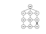
図11は、実施例2に係るシステムの全体構成を示す図である。図11に示すように、このシステムは、GW装置、ノード装置A1からノード装置A3、ノード装置B1からノード装置B3、ノード装置C1からノード装置C3を有する。なお、SLAは、冗長経路の本数=2本とする。
図11は、実施例2に係るシステムの全体構成を示す図である。図11に示すように、このシステムは、GW装置、ノード装置A1からノード装置A3、ノード装置B1からノード装置B3、ノード装置C1からノード装置C3を有する。なお、SLAは、冗長経路の本数=2本とする。
GW装置は、ノード装置A1とノード装置B1とノード装置C1と隣接する、言い換えると、直接通信可能である。ノード装置A1は、GW装置、ノード装置B1、ノード装置A2と隣接する。ノード装置A2は、ノード装置A1、ノード装置B2、ノード装置A3と隣接する。ノード装置A3は、ノード装置A2、ノード装置B3と隣接する。
また、ノード装置B1は、GW装置、ノード装置A1、ノード装置B2、ノード装置C1と隣接する。ノード装置B2は、ノード装置A2、ノード装置B1、ノード装置B3、ノード装置C2と隣接する。ノード装置B3は、ノード装置A3、ノード装置B2、ノード装置C3と隣接する。
また、ノード装置C1は、GW装置、ノード装置B1、ノード装置C2と隣接する。ノード装置C2は、ノード装置B2、ノード装置C1、ノード装置C3と隣接する。ノード装置C3は、ノード装置B3、ノード装置C2と隣接する。
このような状態において、ノード装置C3とノード装置C2との間のリンクが切断された場合、ノード装置C3およびノード装置C2は、ポーリングやHelloパケットの受信有無等によって、リンク切断を検出する。すると、ノード装置C3およびノード装置C2各々は、経路探索を実行する。
このシステムの場合、ノード装置C3は、冗長経路として確認された隣接ノード装置がノード装置B3とノード装置C2であることから、冗長経路を1本しか確保できないこととなり、警告をGW装置に送信する。
一方、ノード装置C2は、冗長経路として確認された隣接ノード装置がノード装置B2、ノード装置C1、ノード装置C3であることから、冗長経路を2本確保できることとなり、SLAを満たすと判定する。そして、ノード装置C2は、確保した隣接ノード装置のうち、例えばノード装置C1に経路探索依頼を送信する。
ここで、経路探索依頼について説明する。図12は、経路探索依頼のフレームフォーマットの例を示す図である。図12に示すように、経路探索依頼は、「原因内容、原因のノード情報、GS、LS、フレームID」から構成される。
ここで記憶される「原因内容」は、経路探索依頼を送信することとなった理由であり、例えば探索実行部14等が「リンク切断の検出」などを格納する。「原因のノード情報」は、経路探索依頼を送信する原因となったノード情報であり、この例では、ノード装置C2の探索実行部14等が「ノード装置C3のMACアドレス」等を格納する。「GS」、「LS」、「フレームID」は、上述したものと同様なので、ここでは省略する。
この例では、例えば、ノード装置C2の探索実行部14等が、「リンク切断の検出、ノード装置C3のMACアドレス、ノード装置C2のMACアドレス、ノード装置C2のMACアドレス、F11」などの経路探索依頼を生成する。
[処理の流れ]
次に、リンク切断に伴って経路探索要求を送信する場合の処理と、経路探索依頼を受信した場合の処理について説明する。
次に、リンク切断に伴って経路探索要求を送信する場合の処理と、経路探索依頼を受信した場合の処理について説明する。
(リンク切断に伴って経路探索要求を送信する場合の処理)
図13は、実施例2に係るノード装置がリンク切断に伴って経路探索要求を送信する場合の処理の流れを示すフローチャートである。図13に示すように、送信部14aは、断線を検出すると(S301肯定)、変数(i)を「0」とする(S302)。
図13は、実施例2に係るノード装置がリンク切断に伴って経路探索要求を送信する場合の処理の流れを示すフローチャートである。図13に示すように、送信部14aは、断線を検出すると(S301肯定)、変数(i)を「0」とする(S302)。
続いて、送信部14aは、ルーティングテーブル12cやリンクテーブル12bを参照し、隣接ノード数がSLA条件を満たすか否か、つまり、隣接ノード数がSLAで規定する本数(N)以上か否かを判定する(S303)。
そして、送信部14aは、隣接ノード数がSLAで規定する本数よりも大きい場合(S303肯定)、経路探索要求を生成して、未送信のノード装置に送信する(S304)。その後、カウント部14cは、GW装置からACKを受信した場合(S305肯定)、変数(i)をインクリメントする(S306)。なお、GW装置からACKを受信できず、タイムアウト等を起こした場合(S305否定)、S306を実行することなく、S307が実行される。
そして、送信制御部14dは、変数(i)がSLA条件を満たすか否か、つまり、ACKの受信数がSLAで規定する本数(N)以上か否かを判定する(S307)。送信制御部14dは、変数(i)がSLA条件(N)を満たす場合(S307肯定)、起点ノード装置からGW装置までの冗長経路を1つ、または冗長経路として確認された隣接ノード装置のうち1つを選択し(S308)、選択した冗長経路上の隣接ノード装置に経路探索依頼を送信して処理を終了する(S309)。一方、送信制御部14dは、変数(i)がSLA条件を満たさない場合(S307否定)、S304以降を繰り返す。
また、S303において、隣接ノード数がSLAで規定する本数よりも小さい場合(S303否定)、警告送信部14eは、警告フレームを生成してGW装置に送信する(S310)。
(経路探索依頼を受信した場合の処理)
図14は、実施例2に係るノード装置が経路探索依頼を受信した場合の処理の流れを示すフローチャートである。図14に示すように、実施例2に係るノード装置が経路探索依頼を受信した場合(S401肯定)、実施例1で説明したS102からS107およびS108と同様の処理である、S402からS407およびS409を実行するので、詳細な説明は省略する。
図14は、実施例2に係るノード装置が経路探索依頼を受信した場合の処理の流れを示すフローチャートである。図14に示すように、実施例2に係るノード装置が経路探索依頼を受信した場合(S401肯定)、実施例1で説明したS102からS107およびS108と同様の処理である、S402からS407およびS409を実行するので、詳細な説明は省略する。
実施例1等と異なる点は、実施例2に係るノード装置は、S407において変数(i)がSLA条件(N)を満たす場合(S407肯定)、GSが選択した冗長経路上の隣接ノード装置、またはGWへの経路候補としてルーティングテーブルに保存されている隣接ノード装置のうち1つに経路探索依頼を送信して処理を終了する(S408)。
[実施例2による効果]
実施例2に係るノード装置は、リンク切断を検出した場合に、自装置で冗長経路探索を実行して、SLAを満たさない場合には警告をGW装置に送信する。一方で、ノード装置は、リンク切断を検出した場合に、自装置の隣接ノード装置に冗長経路の探索依頼を送信する。したがって、リンク切断に関係する最低限のノード装置だけが冗長経路探索を実行するので、少ないトラフィックでネットワーク構成を確認できる。
実施例2に係るノード装置は、リンク切断を検出した場合に、自装置で冗長経路探索を実行して、SLAを満たさない場合には警告をGW装置に送信する。一方で、ノード装置は、リンク切断を検出した場合に、自装置の隣接ノード装置に冗長経路の探索依頼を送信する。したがって、リンク切断に関係する最低限のノード装置だけが冗長経路探索を実行するので、少ないトラフィックでネットワーク構成を確認できる。
さて、これまで本発明の実施例について説明したが、本発明は上述した実施例以外にも、種々の異なる形態にて実施されてよいものである。そこで、以下に異なる実施例を説明する。
(経路探索を実行する契機)
例えば、ノード装置が経路探索を実行する契機は、実施例1や実施例2以外にも任意に設定することができる。例えば、システムに新たに追加されたタイミング、故障から復帰したタイミング、警告を送信後の定期間隔など様々な契機で、経路探索を実行することができる。
例えば、ノード装置が経路探索を実行する契機は、実施例1や実施例2以外にも任意に設定することができる。例えば、システムに新たに追加されたタイミング、故障から復帰したタイミング、警告を送信後の定期間隔など様々な契機で、経路探索を実行することができる。
また、ノード装置自体にボタンを付けるなどし、ユーザによってボタンが押下された場合に、経路探索を実行し、その結果である冗長経路をディスプレイ等に表示させてもよい。こうすることで、ノード装置の設置者は、冗長経路の本数がSLAを満たす箇所にノード装置を設置することができる。
(SLA)
例えば、上述した実施例では、SLAとして、GW装置までの冗長経路の本数が2本である例について説明したが、これに限定されるものではなく、任意に設定変更できる。また、GW装置までの冗長経路ではなく、任意のノード装置や外部のサーバまでなどユーザが任意に設定することができる。
例えば、上述した実施例では、SLAとして、GW装置までの冗長経路の本数が2本である例について説明したが、これに限定されるものではなく、任意に設定変更できる。また、GW装置までの冗長経路ではなく、任意のノード装置や外部のサーバまでなどユーザが任意に設定することができる。
(システム)
また、本実施例において説明した各処理のうち、自動的におこなわれるものとして説明した処理の全部または一部を手動的におこなうこともできる。あるいは、手動的におこなわれるものとして説明した処理の全部または一部を公知の方法で自動的におこなうこともできる。この他、上記文書中や図面中で示した処理手順、制御手順、具体的名称、各種のデータやパラメータを含む情報については、特記する場合を除いて任意に変更することができる。
また、本実施例において説明した各処理のうち、自動的におこなわれるものとして説明した処理の全部または一部を手動的におこなうこともできる。あるいは、手動的におこなわれるものとして説明した処理の全部または一部を公知の方法で自動的におこなうこともできる。この他、上記文書中や図面中で示した処理手順、制御手順、具体的名称、各種のデータやパラメータを含む情報については、特記する場合を除いて任意に変更することができる。
また、図示した各装置の各構成要素は機能概念的なものであり、必ずしも物理的に図示の如く構成されていることを要しない。すなわち、各装置の分散・統合の具体的形態は図示のものに限られない。つまり、その全部または一部を、各種の負荷や使用状況などに応じて、任意の単位で機能的または物理的に分散・統合して構成することができる。さらに、各装置にて行なわれる各処理機能は、その全部または任意の一部が、CPUおよび当該CPUにて解析実行されるプログラムにて実現され、あるいは、ワイヤードロジックによるハードウェアとして実現され得る。
(プログラム)
ところで、上記の実施例で説明した各種の処理は、あらかじめ用意されたプログラムをパーソナルコンピュータやワークステーションなどのコンピュータシステムで実行することによって実現することができる。そこで、以下では、上記の実施例と同様の機能を有するプログラムを実行するコンピュータシステムの一例を説明する。
ところで、上記の実施例で説明した各種の処理は、あらかじめ用意されたプログラムをパーソナルコンピュータやワークステーションなどのコンピュータシステムで実行することによって実現することができる。そこで、以下では、上記の実施例と同様の機能を有するプログラムを実行するコンピュータシステムの一例を説明する。
図15は、冗長経路探索プログラムを実行するコンピュータのハードウェア構成例を示す図である。図15に示すように、コンピュータシステム100は、バス101に、CPU102、入力装置103、出力装置104、通信インタフェース105、HDD(Hard Disk Drive)106、RAM(Random Access Memory)107が接続される。
入力装置103は、マウスやキーボードであり、出力装置104は、ディスプレイなどであり、通信インタフェース105は、NIC(Network Interface Card)などのインタフェースである。HDD106は、冗長経路探索プログラム106aとともに、図6等に示した各テーブル等に記憶される情報を記憶する。記録媒体の例としてHDD106を例に挙げたが、ROM(Read Only Memory)、RAM(Random Access Memory)、CD-ROM等の他のコンピュータ読み取り可能な記録媒体に各種プログラムを格納しておき、コンピュータに読み取らせることとしてもよい。なお、記録媒体を遠隔地に配置し、コンピュータが、その記録媒体にアクセスすることでプログラムを取得して利用してもよい。また、その際、取得したプログラムをそのコンピュータ自身の記録媒体に格納して用いてもよい。
CPU102は、冗長経路探索プログラム106aを読み出してRAM107に展開することで、図2等で説明した各機能を実行する冗長経路探索プロセス107aを動作させる。すなわち、冗長経路探索プロセス107aは、図2に記載した探索実行部14や探索応答部15と同様の機能を実行する。このようにコンピュータシステム100は、プログラムを読み出して実行することで冗長経路探索方法を実行する情報処理装置として動作する。
10 ノード装置
11 無線インタフェース部
12 記憶部
12a 冗長経路テーブル
12b リンクテーブル
12c ルーティングテーブル
12d 転送記録テーブル
13 無線処理部
14 探索実行部
14a 送信部
14b 受信部
14c カウント部
14d 送信制御部
14e 警告送信部
15 探索応答部
15a 情報格納部
15b 判定部
15c 要求転送部
15d 要求応答部
11 無線インタフェース部
12 記憶部
12a 冗長経路テーブル
12b リンクテーブル
12c ルーティングテーブル
12d 転送記録テーブル
13 無線処理部
14 探索実行部
14a 送信部
14b 受信部
14c カウント部
14d 送信制御部
14e 警告送信部
15 探索応答部
15a 情報格納部
15b 判定部
15c 要求転送部
15d 要求応答部
Claims (6)
- 直接通信が可能な通信装置である隣接通信装置のうち、自装置から所定装置までの経路探索を要求する経路探索要求の送信先として未選択である隣接通信装置に、前記経路探索要求を送信する送信部と、
前記送信部によって送信された前記経路探索要求の応答を前記所定装置から受信する受信部と、
前記応答が受信され、経路が確認された隣接通信装置の数が所定数より少なく、かつ、前記未選択である隣接通信装置が存在する場合に、前記送信部に前記経路探索要求の送信を実行させる送信実行部と、
前記応答が受信され、経路が確認された隣接通信装置の数が所定数に達した場合に、前記送信部が実行する前記経路探索要求の送信を停止する送信停止部と、
前記経路が確認された隣接通信装置の数が所定数より少なく、かつ、前記未選択である隣接通信装置が存在しない場合に、前記所定装置に警告を送信する警告送信部と、
を有することを特徴とする通信装置。 - 前記隣接通信装置から経路探索要求を受信した場合に、前記経路探索要求の送信元の通信装置が選択した隣接通信装置以外の隣接通信装置を選択しない条件で、前記経路探索を実行する探索実行部さらに有することを特徴とする請求項1に記載の通信装置。
- 前記送信部は、前記隣接通信装置との間のリンク切断を検出した場合に、前記未選択である隣接通信装置に、前記経路探索要求を送信し、
前記送信停止部は、前記経路探索要求を送信した隣接通信装置の数が所定数に達した場合に、前記送信部が実行する前記経路探索要求の送信を停止するとともに、リンクが切断された隣接通信装置以外の隣接通信装置1基に対して、経路探索の実行を依頼する経路探索依頼を送信することを特徴とする請求項1に記載の通信装置。 - 前記送信部は、前記隣接通信装置から経路探索の実行を依頼する経路探索依頼を受信した場合に、前記未選択である隣接通信装置に、前記経路探索要求を送信し、
前記受信部は、前記送信部によって送信された前記経路探索要求の応答を前記所定装置から受信し、
前記送信実行部は、経路が確認された隣接通信装置の数が所定数より少なく、かつ、前記未選択である隣接通信装置が存在する場合に、前記送信部に前記経路探索要求の送信を実行させ、
前記送信停止部は、経路が確認された隣接通信装置の数が所定数に達した場合に、前記送信部が実行する前記経路探索要求の送信を停止するとともに、前記隣接通信装置のうち前記リンクが切断された隣接通信装置または前記経路探索依頼の送信元の隣接通信装置以外の隣接通信装置に対して、前記経路探索依頼を送信し、
前記警告送信部は、経路が確認された隣接通信装置の数が所定数より少なく、かつ、前記未選択である隣接通信装置が存在しない場合に、前記所定装置に警告を送信するとともに、前記経路探索依頼を終了することを特徴とする請求項1に記載の通信装置。 - コンピュータが、
直接通信が可能な通信装置である隣接通信装置のうち、自コンピュータから所定装置までの経路探索を要求する経路探索要求の送信先として未選択である隣接通信装置に、前記経路探索要求を送信し、
前記送信した前記経路探索要求の応答を前記所定装置から受信し、
前記応答を受信し、経路が確認された隣接通信装置の数が所定数より少なく、かつ、前記未選択である隣接通信装置が存在する場合に、前記経路探索要求の送信を実行し、
前記応答を受信し、経路が確認された隣接通信装置の数が所定数に達した場合に、前記経路探索要求の送信を停止し、
前記経路が確認された隣接通信装置の数が所定数より少なく、かつ、前記未選択である隣接通信装置が存在しない場合に、前記所定装置に警告を送信する、
処理を含んだことを特徴とする経路探索方法。 - コンピュータに、
直接通信が可能な通信装置である隣接通信装置のうち、自プログラムを実行するコンピュータから所定装置までの経路探索を要求する経路探索要求の送信先として未選択である隣接通信装置に、前記経路探索要求を送信し、
前記送信した前記経路探索要求の応答を前記所定装置から受信し、
前記応答を受信し、経路が確認された隣接通信装置の数が所定数より少なく、かつ、前記未選択である隣接通信装置が存在する場合に、前記経路探索要求の送信を実行し、
前記応答を受信し、経路が確認された隣接通信装置の数が所定数に達した場合に、前記経路探索要求の送信を停止し、
前記経路が確認された隣接通信装置の数が所定数より少なく、かつ、前記未選択である隣接通信装置が存在しない場合に、前記所定装置に警告を送信する、
処理を実行させることを特徴とする経路探索プログラム。
Priority Applications (5)
| Application Number | Priority Date | Filing Date | Title |
|---|---|---|---|
| PCT/JP2011/058138 WO2012131960A1 (ja) | 2011-03-30 | 2011-03-30 | 通信装置、経路探索方法および経路探索プログラム |
| JP2013507829A JP5708792B2 (ja) | 2011-03-30 | 2012-03-30 | 通信装置、経路探索方法および経路探索プログラム |
| CN201280015169.3A CN103460759B (zh) | 2011-03-30 | 2012-03-30 | 通信装置以及路径搜索方法 |
| PCT/JP2012/058755 WO2012133857A1 (ja) | 2011-03-30 | 2012-03-30 | 通信装置、経路探索方法および経路探索プログラム |
| US14/037,678 US9203760B2 (en) | 2011-03-30 | 2013-09-26 | Communication device and route search method |
Applications Claiming Priority (1)
| Application Number | Priority Date | Filing Date | Title |
|---|---|---|---|
| PCT/JP2011/058138 WO2012131960A1 (ja) | 2011-03-30 | 2011-03-30 | 通信装置、経路探索方法および経路探索プログラム |
Publications (1)
| Publication Number | Publication Date |
|---|---|
| WO2012131960A1 true WO2012131960A1 (ja) | 2012-10-04 |
Family
ID=46929783
Family Applications (2)
| Application Number | Title | Priority Date | Filing Date |
|---|---|---|---|
| PCT/JP2011/058138 Ceased WO2012131960A1 (ja) | 2011-03-30 | 2011-03-30 | 通信装置、経路探索方法および経路探索プログラム |
| PCT/JP2012/058755 Ceased WO2012133857A1 (ja) | 2011-03-30 | 2012-03-30 | 通信装置、経路探索方法および経路探索プログラム |
Family Applications After (1)
| Application Number | Title | Priority Date | Filing Date |
|---|---|---|---|
| PCT/JP2012/058755 Ceased WO2012133857A1 (ja) | 2011-03-30 | 2012-03-30 | 通信装置、経路探索方法および経路探索プログラム |
Country Status (3)
| Country | Link |
|---|---|
| US (1) | US9203760B2 (ja) |
| CN (1) | CN103460759B (ja) |
| WO (2) | WO2012131960A1 (ja) |
Families Citing this family (4)
| Publication number | Priority date | Publication date | Assignee | Title |
|---|---|---|---|---|
| JP6036841B2 (ja) * | 2012-10-31 | 2016-11-30 | 富士通株式会社 | 通信制御方法、ネットワークシステム、および通信装置 |
| JP6448414B2 (ja) * | 2015-03-03 | 2019-01-09 | シャープ株式会社 | 無線テレメータシステム及び無線通信装置 |
| WO2023205364A1 (en) * | 2022-04-20 | 2023-10-26 | L3Vel, Llc | Computing systems and methods for managing and monitoring mesh-based communication systems |
| US20250244139A1 (en) * | 2024-01-31 | 2025-07-31 | Toyota Jidosha Kabushiki Kaisha | Determining a set of geographic position traces to be used to produce a digital map of a region of interest |
Citations (1)
| Publication number | Priority date | Publication date | Assignee | Title |
|---|---|---|---|---|
| JP2006270535A (ja) * | 2005-03-24 | 2006-10-05 | Matsushita Electric Works Ltd | マルチホップ無線通信装置およびそれにおけるルートテーブル作成方法 |
Family Cites Families (11)
| Publication number | Priority date | Publication date | Assignee | Title |
|---|---|---|---|---|
| JP3779572B2 (ja) | 2001-08-15 | 2006-05-31 | 日本電信電話株式会社 | 光ネットワークシステムおよび光パスルーティング方法 |
| CN1497913A (zh) * | 2002-10-04 | 2004-05-19 | 株式会社Ntt都科摩 | 路径控制装置及路径控制信息生成方法 |
| WO2005117365A1 (ja) | 2004-05-28 | 2005-12-08 | Nec Corporation | 通信制御装置及び通信制御方法 |
| JP4800067B2 (ja) | 2006-02-21 | 2011-10-26 | 株式会社エヌ・ティ・ティ・ドコモ | 通信ノード及びルーティング方法 |
| JP2008193543A (ja) * | 2007-02-07 | 2008-08-21 | Fujitsu Ltd | アドホックネットワークの経路を制御する装置および方法 |
| WO2009100533A1 (en) * | 2008-02-15 | 2009-08-20 | Research In Motion Limited | Systems and methods for assignment and allocation of mixed-type combinations of slots |
| JP4927016B2 (ja) * | 2008-03-31 | 2012-05-09 | トヨタ自動車株式会社 | ナビゲーションシステムおよびそれを備えたハイブリッド車両 |
| JP4941397B2 (ja) * | 2008-04-22 | 2012-05-30 | 富士通株式会社 | 経路情報中継方法および無線端末 |
| BRPI0911155A2 (pt) * | 2008-04-25 | 2015-10-06 | Fujitsu Ltd | dispositivo de nodo e programa |
| JP2010098591A (ja) * | 2008-10-17 | 2010-04-30 | Fujitsu Ltd | 障害監視システム、サーバ装置およびノード装置 |
| WO2013057773A1 (ja) * | 2011-10-17 | 2013-04-25 | 富士通株式会社 | プログラム、情報処理装置、および経路設定方法 |
-
2011
- 2011-03-30 WO PCT/JP2011/058138 patent/WO2012131960A1/ja not_active Ceased
-
2012
- 2012-03-30 CN CN201280015169.3A patent/CN103460759B/zh not_active Expired - Fee Related
- 2012-03-30 WO PCT/JP2012/058755 patent/WO2012133857A1/ja not_active Ceased
-
2013
- 2013-09-26 US US14/037,678 patent/US9203760B2/en not_active Expired - Fee Related
Patent Citations (1)
| Publication number | Priority date | Publication date | Assignee | Title |
|---|---|---|---|---|
| JP2006270535A (ja) * | 2005-03-24 | 2006-10-05 | Matsushita Electric Works Ltd | マルチホップ無線通信装置およびそれにおけるルートテーブル作成方法 |
Non-Patent Citations (2)
| Title |
|---|
| NOBUYUKI NAKAMURA: "Low latency route switching for wireless ad hoc networks", IEICE TECHNICAL REPORT, vol. 103, no. 425, 7 November 2003 (2003-11-07), pages 13 - 18 * |
| SHINJI MOTEGI: "Proposal on Multipath Routing for Ad hoc Networks", IPSJ SIG NOTES, vol. 2002, no. 106, 15 November 2002 (2002-11-15), pages 125 - 130 * |
Also Published As
| Publication number | Publication date |
|---|---|
| US9203760B2 (en) | 2015-12-01 |
| CN103460759B (zh) | 2016-09-14 |
| WO2012133857A1 (ja) | 2012-10-04 |
| CN103460759A (zh) | 2013-12-18 |
| US20140029469A1 (en) | 2014-01-30 |
Similar Documents
| Publication | Publication Date | Title |
|---|---|---|
| US20240147413A1 (en) | Mapping and Bridging Wireless Networks to Provide Better Service | |
| US8121077B2 (en) | Relay device and relay method | |
| Chilamkurti et al. | Cross‐layer support for energy efficient routing in wireless sensor networks | |
| JP6036841B2 (ja) | 通信制御方法、ネットワークシステム、および通信装置 | |
| JP6239636B2 (ja) | ワイヤレス通信のレンジ拡大(rangeextension)のためのシステム、装置、および方法 | |
| CN103765975A (zh) | 通过扩展服务集的直接链路建立 | |
| JPWO2013088498A1 (ja) | 送信制御方法、ノードおよび送信制御プログラム | |
| JP2009302694A (ja) | 無線通信ネットワークシステム | |
| JP2011124624A (ja) | ビーコンによる通信パラメータ設定機能を有する無線アクセスポイント | |
| JP2018085603A (ja) | 無線通信装置、方法およびプログラム | |
| US9537986B2 (en) | Dynamic contact sharing in a mesh network | |
| CN103460759B (zh) | 通信装置以及路径搜索方法 | |
| JPWO2013042209A1 (ja) | データ転送方法およびそれを用いるノード装置 | |
| JP6478367B2 (ja) | 情報管理装置、ローカルネットワークシステム、情報管理方法および情報管理プログラム | |
| JP3775430B2 (ja) | 網サービス情報提供システム及び網サービス情報提供装置並びにその方法及びその動作制御方法 | |
| JP5860135B2 (ja) | 通信機器探索方法、通信機器、通信機器探索プログラムおよびアドホックネットワークシステム | |
| JP5708792B2 (ja) | 通信装置、経路探索方法および経路探索プログラム | |
| Bharti et al. | Enhanced path routing with buffer allocation method using coupling node selection algorithm in MANET | |
| JPWO2013065131A1 (ja) | 送信制御方法および送信制御装置 | |
| CN117412401A (zh) | 蓝牙网络建立系统及方法 | |
| CN100561973C (zh) | 一种防止无线网格路由拥塞的方法 | |
| JPWO2006075402A1 (ja) | オープンループネットワークノード装置及びオープンループネットワーク制御方法 | |
| JP6345560B2 (ja) | 通信装置システムおよびプログラム | |
| JP2016072812A (ja) | 通信装置システムおよびプログラム | |
| JP5712731B2 (ja) | ノード装置、ノード装置の制御方法およびノード装置の制御プログラム |
Legal Events
| Date | Code | Title | Description |
|---|---|---|---|
| 121 | Ep: the epo has been informed by wipo that ep was designated in this application |
Ref document number: 11862068 Country of ref document: EP Kind code of ref document: A1 |
|
| NENP | Non-entry into the national phase |
Ref country code: DE |
|
| 122 | Ep: pct application non-entry in european phase |
Ref document number: 11862068 Country of ref document: EP Kind code of ref document: A1 |
|
| NENP | Non-entry into the national phase |
Ref country code: JP |