WO2012131875A1 - 内燃機関の排気浄化装置 - Google Patents
内燃機関の排気浄化装置 Download PDFInfo
- Publication number
- WO2012131875A1 WO2012131875A1 PCT/JP2011/057655 JP2011057655W WO2012131875A1 WO 2012131875 A1 WO2012131875 A1 WO 2012131875A1 JP 2011057655 W JP2011057655 W JP 2011057655W WO 2012131875 A1 WO2012131875 A1 WO 2012131875A1
- Authority
- WO
- WIPO (PCT)
- Prior art keywords
- exhaust
- temperature
- throttle valve
- exhaust purification
- internal combustion
- Prior art date
- Legal status (The legal status is an assumption and is not a legal conclusion. Google has not performed a legal analysis and makes no representation as to the accuracy of the status listed.)
- Ceased
Links
Images






Classifications
-
- F—MECHANICAL ENGINEERING; LIGHTING; HEATING; WEAPONS; BLASTING
- F01—MACHINES OR ENGINES IN GENERAL; ENGINE PLANTS IN GENERAL; STEAM ENGINES
- F01N—GAS-FLOW SILENCERS OR EXHAUST APPARATUS FOR MACHINES OR ENGINES IN GENERAL; GAS-FLOW SILENCERS OR EXHAUST APPARATUS FOR INTERNAL-COMBUSTION ENGINES
- F01N3/00—Exhaust or silencing apparatus having means for purifying, rendering innocuous, or otherwise treating exhaust
- F01N3/08—Exhaust or silencing apparatus having means for purifying, rendering innocuous, or otherwise treating exhaust for rendering innocuous
- F01N3/10—Exhaust or silencing apparatus having means for purifying, rendering innocuous, or otherwise treating exhaust for rendering innocuous by thermal or catalytic conversion of noxious components of exhaust
- F01N3/18—Exhaust or silencing apparatus having means for purifying, rendering innocuous, or otherwise treating exhaust for rendering innocuous by thermal or catalytic conversion of noxious components of exhaust characterised by methods of operation; Control
- F01N3/20—Exhaust or silencing apparatus having means for purifying, rendering innocuous, or otherwise treating exhaust for rendering innocuous by thermal or catalytic conversion of noxious components of exhaust characterised by methods of operation; Control specially adapted for catalytic conversion
- F01N3/2006—Periodically heating or cooling catalytic reactors, e.g. at cold starting or overheating
- F01N3/2033—Periodically heating or cooling catalytic reactors, e.g. at cold starting or overheating using a fuel burner or introducing fuel into exhaust duct
-
- F—MECHANICAL ENGINEERING; LIGHTING; HEATING; WEAPONS; BLASTING
- F01—MACHINES OR ENGINES IN GENERAL; ENGINE PLANTS IN GENERAL; STEAM ENGINES
- F01N—GAS-FLOW SILENCERS OR EXHAUST APPARATUS FOR MACHINES OR ENGINES IN GENERAL; GAS-FLOW SILENCERS OR EXHAUST APPARATUS FOR INTERNAL-COMBUSTION ENGINES
- F01N3/00—Exhaust or silencing apparatus having means for purifying, rendering innocuous, or otherwise treating exhaust
- F01N3/02—Exhaust or silencing apparatus having means for purifying, rendering innocuous, or otherwise treating exhaust for cooling, or for removing solid constituents of, exhaust
- F01N3/021—Exhaust or silencing apparatus having means for purifying, rendering innocuous, or otherwise treating exhaust for cooling, or for removing solid constituents of, exhaust by means of filters
- F01N3/023—Exhaust or silencing apparatus having means for purifying, rendering innocuous, or otherwise treating exhaust for cooling, or for removing solid constituents of, exhaust by means of filters using means for regenerating the filters, e.g. by burning trapped particles
- F01N3/025—Exhaust or silencing apparatus having means for purifying, rendering innocuous, or otherwise treating exhaust for cooling, or for removing solid constituents of, exhaust by means of filters using means for regenerating the filters, e.g. by burning trapped particles using fuel burner or by adding fuel to exhaust
-
- F—MECHANICAL ENGINEERING; LIGHTING; HEATING; WEAPONS; BLASTING
- F01—MACHINES OR ENGINES IN GENERAL; ENGINE PLANTS IN GENERAL; STEAM ENGINES
- F01N—GAS-FLOW SILENCERS OR EXHAUST APPARATUS FOR MACHINES OR ENGINES IN GENERAL; GAS-FLOW SILENCERS OR EXHAUST APPARATUS FOR INTERNAL-COMBUSTION ENGINES
- F01N3/00—Exhaust or silencing apparatus having means for purifying, rendering innocuous, or otherwise treating exhaust
- F01N3/08—Exhaust or silencing apparatus having means for purifying, rendering innocuous, or otherwise treating exhaust for rendering innocuous
- F01N3/10—Exhaust or silencing apparatus having means for purifying, rendering innocuous, or otherwise treating exhaust for rendering innocuous by thermal or catalytic conversion of noxious components of exhaust
- F01N3/18—Exhaust or silencing apparatus having means for purifying, rendering innocuous, or otherwise treating exhaust for rendering innocuous by thermal or catalytic conversion of noxious components of exhaust characterised by methods of operation; Control
- F01N3/20—Exhaust or silencing apparatus having means for purifying, rendering innocuous, or otherwise treating exhaust for rendering innocuous by thermal or catalytic conversion of noxious components of exhaust characterised by methods of operation; Control specially adapted for catalytic conversion
- F01N3/206—Adding periodically or continuously substances to exhaust gases for promoting purification, e.g. catalytic material in liquid form, NOx reducing agents
- F01N3/2066—Selective catalytic reduction [SCR]
-
- F—MECHANICAL ENGINEERING; LIGHTING; HEATING; WEAPONS; BLASTING
- F01—MACHINES OR ENGINES IN GENERAL; ENGINE PLANTS IN GENERAL; STEAM ENGINES
- F01N—GAS-FLOW SILENCERS OR EXHAUST APPARATUS FOR MACHINES OR ENGINES IN GENERAL; GAS-FLOW SILENCERS OR EXHAUST APPARATUS FOR INTERNAL-COMBUSTION ENGINES
- F01N3/00—Exhaust or silencing apparatus having means for purifying, rendering innocuous, or otherwise treating exhaust
- F01N3/08—Exhaust or silencing apparatus having means for purifying, rendering innocuous, or otherwise treating exhaust for rendering innocuous
- F01N3/10—Exhaust or silencing apparatus having means for purifying, rendering innocuous, or otherwise treating exhaust for rendering innocuous by thermal or catalytic conversion of noxious components of exhaust
- F01N3/24—Exhaust or silencing apparatus having means for purifying, rendering innocuous, or otherwise treating exhaust for rendering innocuous by thermal or catalytic conversion of noxious components of exhaust characterised by constructional aspects of converting apparatus
- F01N3/36—Arrangements for supply of additional fuel
-
- F—MECHANICAL ENGINEERING; LIGHTING; HEATING; WEAPONS; BLASTING
- F01—MACHINES OR ENGINES IN GENERAL; ENGINE PLANTS IN GENERAL; STEAM ENGINES
- F01N—GAS-FLOW SILENCERS OR EXHAUST APPARATUS FOR MACHINES OR ENGINES IN GENERAL; GAS-FLOW SILENCERS OR EXHAUST APPARATUS FOR INTERNAL-COMBUSTION ENGINES
- F01N2240/00—Combination or association of two or more different exhaust treating devices, or of at least one such device with an auxiliary device, not covered by indexing codes F01N2230/00 or F01N2250/00, one of the devices being
- F01N2240/14—Combination or association of two or more different exhaust treating devices, or of at least one such device with an auxiliary device, not covered by indexing codes F01N2230/00 or F01N2250/00, one of the devices being a fuel burner
-
- F—MECHANICAL ENGINEERING; LIGHTING; HEATING; WEAPONS; BLASTING
- F01—MACHINES OR ENGINES IN GENERAL; ENGINE PLANTS IN GENERAL; STEAM ENGINES
- F01N—GAS-FLOW SILENCERS OR EXHAUST APPARATUS FOR MACHINES OR ENGINES IN GENERAL; GAS-FLOW SILENCERS OR EXHAUST APPARATUS FOR INTERNAL-COMBUSTION ENGINES
- F01N2240/00—Combination or association of two or more different exhaust treating devices, or of at least one such device with an auxiliary device, not covered by indexing codes F01N2230/00 or F01N2250/00, one of the devices being
- F01N2240/36—Combination or association of two or more different exhaust treating devices, or of at least one such device with an auxiliary device, not covered by indexing codes F01N2230/00 or F01N2250/00, one of the devices being an exhaust flap
-
- F—MECHANICAL ENGINEERING; LIGHTING; HEATING; WEAPONS; BLASTING
- F01—MACHINES OR ENGINES IN GENERAL; ENGINE PLANTS IN GENERAL; STEAM ENGINES
- F01N—GAS-FLOW SILENCERS OR EXHAUST APPARATUS FOR MACHINES OR ENGINES IN GENERAL; GAS-FLOW SILENCERS OR EXHAUST APPARATUS FOR INTERNAL-COMBUSTION ENGINES
- F01N2610/00—Adding substances to exhaust gases
- F01N2610/02—Adding substances to exhaust gases the substance being ammonia or urea
-
- F—MECHANICAL ENGINEERING; LIGHTING; HEATING; WEAPONS; BLASTING
- F01—MACHINES OR ENGINES IN GENERAL; ENGINE PLANTS IN GENERAL; STEAM ENGINES
- F01N—GAS-FLOW SILENCERS OR EXHAUST APPARATUS FOR MACHINES OR ENGINES IN GENERAL; GAS-FLOW SILENCERS OR EXHAUST APPARATUS FOR INTERNAL-COMBUSTION ENGINES
- F01N2610/00—Adding substances to exhaust gases
- F01N2610/03—Adding substances to exhaust gases the substance being hydrocarbons, e.g. engine fuel
-
- Y—GENERAL TAGGING OF NEW TECHNOLOGICAL DEVELOPMENTS; GENERAL TAGGING OF CROSS-SECTIONAL TECHNOLOGIES SPANNING OVER SEVERAL SECTIONS OF THE IPC; TECHNICAL SUBJECTS COVERED BY FORMER USPC CROSS-REFERENCE ART COLLECTIONS [XRACs] AND DIGESTS
- Y02—TECHNOLOGIES OR APPLICATIONS FOR MITIGATION OR ADAPTATION AGAINST CLIMATE CHANGE
- Y02T—CLIMATE CHANGE MITIGATION TECHNOLOGIES RELATED TO TRANSPORTATION
- Y02T10/00—Road transport of goods or passengers
- Y02T10/10—Internal combustion engine [ICE] based vehicles
- Y02T10/12—Improving ICE efficiencies
Definitions
- the present invention relates to an exhaust purification device for an internal combustion engine.
- a burner consisting of a fuel supply unit and an ignition unit is provided upstream of the catalyst in the exhaust passage.
- a technique for operating and warming up a downstream SCR catalyst by burning a burner is disclosed (see, for example, Patent Document 1).
- the temperature raising part such as a catalyst warm-up burner is generally arranged on the upstream side of the exhaust gas purification part of the exhaust passage, and causes the heated exhaust gas to flow into the exhaust gas purification part such as the catalyst.
- the heat distribution is not taken into account at the time of temperature rise, the temperature distribution in the piping, exhaust purification section, etc. becomes particularly large, especially in regions with a small amount of air, resulting in uneven thermal expansion. There is also a risk of damage.
- the temperature of the catalyst is unevenly increased as the exhaust purification unit, the other part of the catalyst is still stagnant in the inactive temperature range even though a part of the catalyst has already reached the activation temperature range. Even in the same catalyst, a difference in purification rate due to a difference in bed temperature occurs depending on the part, which causes a problem that it becomes difficult to manage the purification rate of the catalyst.
- the present invention has been made in view of the above circumstances, and an object of the present invention is to provide a technique for uniformly raising the temperature of the exhaust purification unit by the temperature raising unit.
- the present invention An exhaust purification unit disposed in an exhaust passage of the internal combustion engine for purifying exhaust; A temperature raising unit that is disposed in the exhaust passage upstream of the exhaust purification unit and generates a flame by burning the supplied fuel; and A throttle valve that is disposed in the exhaust passage between the temperature raising unit and the exhaust purification unit, and is capable of changing a flow direction or amount of exhaust;
- An exhaust emission control device for an internal combustion engine comprising:
- examples of the exhaust purification unit include a NOx selective reduction catalyst (SCR catalyst), a NOx occlusion reduction catalyst, a catalyst such as a three-way catalyst, an oxidation catalyst, and a filter such as DPF.
- SCR catalyst NOx selective reduction catalyst
- NOx occlusion reduction catalyst a catalyst such as a three-way catalyst
- oxidation catalyst a catalyst such as a three-way catalyst
- DPF filter
- the throttle valve can change the flow direction or amount of the exhaust gas whose temperature has been raised in the temperature raising portion. For this reason, considering the heat distribution (dispersibility) by the throttle valve, the exhaust gas whose temperature has been raised can be made to flow downstream. For example, the flow direction or amount of the exhaust gas is changed so that the exhaust gas is dispersed by varying the opening of the throttle valve, or more exhaust gas is flowed to the low temperature side, so that the heat distribution (dispersibility) becomes uniform. be able to. Therefore, even in a region where the amount of air is particularly small, the temperature distribution in the piping and the exhaust purification section is small, and damage due to uneven thermal expansion can be suppressed.
- the temperature of the catalyst as the exhaust purification unit is also raised uniformly, other parts of the catalyst are still stagnant in the inactive temperature range even though part of the catalyst has already reached the activation temperature range, etc. Even in the same catalyst, since the difference in the purification rate due to the difference in the bed temperature is suppressed depending on the portion, the management of the catalyst purification rate becomes easy.
- the temperature of the exhaust purification unit can be uniformly raised by the temperature raising unit.
- the throttle valve may block a flame generated in the temperature raising part.
- the flame generated in the temperature raising section reaches the exhaust purification section as it is, there is a risk of causing thermal degradation such as sintering of the noble metal supported on the catalyst as the exhaust purification section.
- the exhaust purification unit is provided with a DPF, the PM or SOF deposited on the DPF is burned by the flame from the temperature raising unit, so that there is a possibility that the temperature of the DPF increases rapidly and thermal degradation occurs.
- the flame generated in the temperature raising portion due to the increase in the heat mass of the throttle valve or the increase in the back pressure is blocked by the throttle valve, the flame tip near the throttle valve is extinguished, and the flame does not reach the exhaust purification section.
- the combustion space in which the temperature raising portion is combusted is provided in the exhaust passage, it is not necessary to provide the entire temperature raising portion itself in the combustion region, and the temperature raising portion can be downsized. it can.
- the exhaust passage upstream of the throttle valve further includes an addition section for adding an additive to be supplied to the exhaust purification section.
- the additive includes an oxidizer and a reductant supplied to the exhaust gas purification unit, or a fuel for an internal combustion engine.
- the additive added in the addition section can collide with the throttle valve. Since the throttle valve functions as a dispersion plate, the dispersibility of the additive colliding with the throttle valve can be improved. Further, even when the solid material of the additive is deposited and deposited on the throttle valve, the solid material can be dissolved and removed by the temperature rise in the temperature raising portion.
- the temperature of the exhaust purification unit can be raised uniformly by the temperature raising unit.
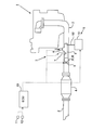
- FIG. 1 is a diagram illustrating a schematic configuration of an internal combustion engine according to Embodiment 1 of the present invention. It is a figure which shows the throttle valve which concerns on Example 1.
- FIG. It is a figure which shows the temperature increase promotion mode which concerns on Example 1.
- FIG. It is a figure which shows the throttle valve which concerns on the modification 2.
- FIG. It is a figure which shows the throttle valve which concerns on the modification 3.
- FIG. It is a figure which shows the throttle valve which concerns on the modification 4.
- FIG. FIG. 3 is a diagram illustrating a schematic configuration of an internal combustion engine according to a second embodiment.
- FIG. 6 is a diagram illustrating a schematic configuration of an internal combustion engine according to a third embodiment.
- FIG. 6 is a diagram illustrating a schematic configuration of an internal combustion engine according to a fourth embodiment.
- FIG. 1 is a diagram illustrating a schematic configuration of an internal combustion engine 1 to which an exhaust gas purification apparatus for an internal combustion engine according to a first embodiment of the present invention is applied.
- the internal combustion engine 1 shown in FIG. 1 is a four-stroke cycle diesel engine.
- the internal combustion engine 1 is not limited to a diesel engine, and may be another engine such as a gasoline engine.
- the internal combustion engine 1 is connected to an exhaust passage 2 through which exhaust gas discharged to the atmosphere after combustion in the engine is circulated.
- An exhaust temperature raising device 3 is provided in the exhaust passage 2.
- the exhaust temperature raising device 3 is disposed in the exhaust passage 2 upstream of an exhaust purification catalyst 4 described later, and generates a flame to burn the supplied fuel.
- the exhaust temperature raising device 3 corresponds to the temperature raising unit of the present invention.
- An exhaust purification catalyst 4 is provided in the exhaust passage 2 downstream of the exhaust temperature raising device 3.
- the exhaust temperature raising device 3 raises the temperature of the exhaust gas, and the exhaust gas heated to a high temperature flows into the exhaust purification catalyst 4.
- the exhaust purification catalyst 4 is activated by raising the temperature of the exhaust gas flowing in, and exhibits its function.
- Examples of the exhaust purification catalyst 4 include a NOx selective reduction catalyst (SCR catalyst), a NOx storage reduction catalyst, an oxidation catalyst, and a three-way catalyst.
- the exhaust purification catalyst 4 corresponds to the exhaust purification section of the present invention.
- a diesel particulate filter (DPF) that collects particulate matter (PM) in the exhaust is provided in the exhaust passage 2 downstream of the exhaust temperature raising device 3. Good.
- the exhaust gas temperature raising device 3 raises the temperature of the exhaust gas, and the exhaust gas heated to a high temperature flows into the DPF.
- the DPF forcibly oxidizes and removes PM collected by the DPF using high-temperature exhaust gas flowing in.
- the DPF corresponds to the exhaust gas purification unit of the present invention.
- the exhaust temperature raising device 3 does not constantly raise the temperature of the exhaust gas, but as described above, the timing for activating the exhaust purification catalyst 4 and the timing for forcibly removing the PM collected in the DPF. Then, raise the temperature of the exhaust.
- the exhaust temperature raising device 3 provided in the exhaust passage upstream of the exhaust purification catalyst 4 includes an air supply device 5, a fuel supply valve 6, an ignition device 7, and a combustion chamber surrounding them from the upstream side in the exhaust flow direction. 8.
- the air supply device 5 supplies air from the air pump 51 through the air supply passage 52 into the exhaust passage 2 (inside the combustion chamber 8), and increases the oxygen concentration of the exhaust gas in the combustion chamber 8.
- the fuel supply valve 6 is provided in the exhaust passage 2 of the internal combustion engine 1 and supplies fuel in a fuel tank (not shown) into the exhaust passage 2 (inside the combustion chamber 8). The fuel supply valve 6 injects fuel from the injection hole according to a signal from the ECU 10.
- the ignition device 7 is provided in the exhaust passage 2 of the internal combustion engine 1 and ignites (ignites) the fuel supplied from the fuel supply valve 6 in the combustion chamber 8.
- the ignition device 7 for example, a device that generates a spark discharge such as a spark plug, or a device that includes an ignition part that glows when energized, such as a glow plug, is used.
- the fuel ignited by the ignition device 7 generates a flame and burns.
- the combustion chamber 8 has a cylindrical shape opened in the upstream and downstream sides disposed in the exhaust passage 2, and air from the air supply device 5 and fuel from the fuel supply valve 6 are supplied to the inside. It is made possible for the ignition device 7 to perform ignition in a state where is mixed.
- the combustion chamber 8 is provided in the exhaust passage 2 so that the air from the air supply device 5 and the fuel from the fuel supply valve 6 are mixed without being excessively diffused in the entire exhaust passage 2. Further, the influence of the exhaust gas flowing in the exhaust passage 2 on the exhaust temperature raising device 3 is reduced. Thereby, the exhaust temperature raising device 3 can stably burn the fuel. Note that the flame from the exhaust temperature raising device 3 is generated by extending to the exhaust passage downstream of the combustion chamber 8. Further, the exhaust temperature raising device 3 is not limited to the above configuration. For example, the air may not be supplied, or the combustion chamber 8 may not be provided.
- FIG. 2 is a diagram illustrating the throttle valve 9 according to the present embodiment.
- the throttle valve 9 has a valve body 91 that covers the exhaust gas vertical section of the exhaust passage 2 and a valve shaft 92 that rotates the valve body 91, and controls the opening degree by a signal from the ECU 10. be able to.
- the opening degree of the throttle valve 9 By controlling the opening degree of the throttle valve 9, the flow direction or amount of the exhaust gas heated by the exhaust gas temperature raising device 3 can be changed.
- FIG. 2 is a diagram illustrating the throttle valve 9 according to the present embodiment.
- the throttle valve 9 has a valve body 91 that covers the exhaust gas vertical section of the exhaust passage 2 and a valve shaft 92 that rotates the valve body 91, and controls the opening degree by a signal from the ECU 10. be able to.
- the valve body 91 of the throttle valve 9 is formed with a plurality of holes 93 that allow the exhaust gas to flow downstream while blocking the flame emitted from the exhaust gas temperature raising device 3.
- the hole diameters of the plurality of hole portions 93 are set so that the exhaust gas flows downstream while blocking the flame emitted from the exhaust gas temperature raising device 3.
- the internal combustion engine 1 is provided with an ECU (Electronic Control Unit) 10 for controlling the internal combustion engine 1.
- the ECU 10 is a unit that controls the operation state of the internal combustion engine 1 in accordance with the operation conditions of the internal combustion engine 1 and the request of the driver.
- Various sensors such as a crank position sensor 11 and an accelerator position sensor 12 are connected to the ECU 10 via electric wiring, and output signals of these various sensors are input to the ECU 10.
- an air supply device 5 a fuel supply valve 6, an ignition device 7, and a throttle valve 9 are connected to the ECU 10 through electrical wiring, and these devices are controlled by the ECU 10.
- the ECU 10 supplies air from the air supply device 5 and injects fuel from the fuel supply valve 6 at a timing when the exhaust gas needs to be heated based on detection values of various sensors, and performs ignition by the ignition device 7. .
- the floor temperature of the exhaust purification catalyst 4 is equal to or lower than a predetermined temperature and the exhaust purification catalyst 4 needs to be warmed up, it is determined that the temperature of exhaust gas needs to be raised.
- the operation time of the internal combustion engine 1 has elapsed for a predetermined time and the forced oxidation removal of the particulate matter collected in the DPF is necessary, it is determined that the temperature of the exhaust gas needs to be raised.
- the exhaust gas temperature raising device 3 is arranged upstream of the exhaust gas purification catalyst 4 and causes the heated exhaust gas to flow into the exhaust gas purification catalyst 4. If the heat distribution (dispersibility) is not taken into account when the temperature is increased, the temperature distribution in the piping, the exhaust purification catalyst 4 and the like becomes large, particularly in a region where the amount of air is small, due to uneven thermal expansion. There is also a risk of damage. Further, the temperature of the exhaust purification catalyst 4 is raised unevenly, so that even though a part of the exhaust purification catalyst 4 has already reached the activation temperature range, the other part of the exhaust purification catalyst 4 is still at the inactive temperature.
- a throttle valve 9 is disposed between the exhaust temperature raising device 3 and the exhaust purification catalyst 4.
- the throttle valve 9 can change the flow direction or amount of the exhaust gas heated by the exhaust gas temperature raising device 3. For this reason, considering the heat distribution (dispersibility) by the throttle valve 9, the exhaust gas whose temperature has been raised can flow downstream.
- the flow direction or amount of the exhaust is changed so that the exhaust is dispersed by swinging the opening of the throttle valve 9 in various sizes, or more exhaust is allowed to flow on the low temperature side, so that the heat distribution (dispersibility) is uniform. can do.
- the exhaust purification catalyst 4 can be uniformly heated by the exhaust temperature raising device 3.
- the flame generated in the exhaust gas temperature raising device 3 due to the increase in the heat mass of the throttle valve 9 and the increase in the back pressure is blocked by the throttle valve 9 and the flame front in the vicinity of the throttle valve 9 is extinguished. Does not reach the exhaust purification catalyst 4. Therefore, it is possible to suppress thermal degradation such as sintering of the noble metal supported on the exhaust purification catalyst 4.
- the exhaust purification unit is equipped with a DPF, it is avoided that PM and SOF accumulated in the DPF are burned by the flame from the temperature raising unit, and the temperature of the DPF is rapidly increased to suppress thermal deterioration. Can do.
- FIG. 3 is a diagram showing a temperature increase promotion mode according to the present embodiment.
- the flame emitted from the exhaust temperature raising device 3 may be guided downstream by the throttle valve 9. Thereby, it is possible to facilitate the flow of a flame into the exhaust purification catalyst 4 at a low temperature and to promote warm-up.
- the throttle valve 9 shown in FIG. 1 is made of a porous material such as a sintered material. In this case, it is not necessary to provide a plurality of holes in the valve body. Since the material of the throttle valve 9 is a porous body, the exhaust can be circulated downstream while blocking the flame emitted from the exhaust temperature raising device 3.
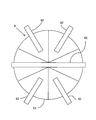
- FIG. 4 is a view showing a throttle valve 9 according to the second modification.
- the throttle valve 9 according to the modified example 2 has a valve body 91 divided into six parts, and rotates two valve bodies 91 opposed to the left and right with a valve shaft 92 extending in the horizontal direction.
- the remaining four valve bodies 91 are each provided with a valve shaft 92 extending from the circumferential surface of the exhaust passage 2 so that the exhaust passage 2 can be opened and closed for each portion.
- FIG. 5 is a view showing a throttle valve 9 according to the third modification.
- FIG. 5A shows a state in which the valve body 91 of the throttle valve 9 is contracted to a small size
- FIG. 5B shows a state in which the valve body 91 of the throttle valve 9 is greatly expanded as a whole.
- the throttle valve 9 according to the modified example 3 has a central valve shaft 92 that extends in the exhaust flow direction and is rotatable, and the main shaft shape has a width in the exhaust flow direction.
- the valve body 91 is wound. By reducing or increasing the size of the mainspring-like valve body 91 as a center, the flow direction or amount of the exhaust gas can be changed while blocking the flame emitted from the exhaust gas temperature raising device 3.
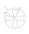
- FIG. 6 is a view showing a throttle valve 9 according to the fourth modification.
- the throttle valve 9 according to the modified example 4 includes one fixed plate having four holes 94 and one valve body disposed on the back of the fixed plate. By rotating only the opening and closing, the flow direction or amount of the exhaust gas can be changed by opening and closing the four holes 94 with the valve body.
- FIG. 7 is a view showing a throttle valve 9 according to the fifth modification.
- the throttle valve 9 according to the modified example 5 four deformable plate members 95 spreading in a spiral shape can be rotated in the cross section of the exhaust passage. By rotating the central valve shaft 92, the four plate members 95 are rotated, and the flow direction of the exhaust gas is changed while blocking the flame emitted from the exhaust gas temperature raising device 3.
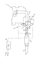
- FIG. 8 is a diagram showing the internal combustion engine 1 according to the second embodiment of the present invention.
- a combustion space 13 in which combustion of the exhaust temperature raising device 3 is performed is provided in the exhaust passage 2 between the exhaust temperature raising device 3 and the throttle valve 9.
- the combustion space 13 is usually provided in a region where a flame exiting the exhaust temperature raising device 3 exists. Since other configurations are the same as those in the above embodiment, the description thereof is omitted.
- the combustion space 13 in which the exhaust temperature raising device 3 is combusted is provided in the exhaust passage 2, it is not necessary to provide the entire region in which the combustion is performed in the exhaust temperature raising device 3 itself.
- the temperature raising device 3 can be reduced in size.
- FIG. 9 is a diagram showing an internal combustion engine 1 according to Embodiment 3 of the present invention.
- the exhaust passage upstream of the exhaust purification catalyst 4 is divided into two stages, and the exhaust temperature raising device 3 and the throttle valve 9 are arranged in one divided branch.
- Nothing is arranged on the other shunt. Since other configurations are the same as those in the above embodiment, the description thereof is omitted.
- the flame emitted from the exhaust temperature raising device 3 is not only blocked by the throttle valve 9, but also exhaust gas flows into the other shunt and a reverse flow occurs in the one shunt. Try to sneak into the other shunt. As a result, the distance between the flame and the exhaust purification catalyst 4 can be increased, and the flame front does not reach the exhaust purification catalyst 4.
- FIG. 10 is a view showing an internal combustion engine 1 according to Embodiment 4 of the present invention.
- an addition valve 14 for adding an additive to be supplied to the exhaust purification catalyst 4 is arranged in the exhaust temperature raising device 3. Since other configurations are the same as those in the above embodiment, the description thereof is omitted.
- an addition valve 14 is arranged in the exhaust gas temperature raising device 3.
- the addition valve 14 corresponds to the addition portion of the present invention.
- An additive to be supplied to the exhaust purification catalyst 4 is added from the addition valve 14.
- the addition valve 14 is arranged in the exhaust temperature raising device 3.
- the addition valve 14 is disposed in the exhaust passage 2 upstream of the throttle valve 9 in the exhaust purification catalyst 4. Additives to be supplied to may be added. Therefore, for example, the addition valve 14 may add an additive toward the flame that is emitted from the exhaust temperature raising device 3.
- the addition valve 14 may add an additive from the exhaust passage 2 upstream of the exhaust temperature raising device 3.
- the addition valve 14 may add an additive such that the additive adheres to the throttle valve 9.
- the additive added by the addition valve 14 can collide with the throttle valve 9. Since the throttle valve 9 functions as a dispersion plate, the dispersibility of the additive colliding with the throttle valve 9 can be improved. Further, even when the additive solid substance is deposited and deposited on the throttle valve 9, the solid substance can be dissolved and removed by the temperature rise in the exhaust gas temperature raising device 3. For example, when the additive is urea water, cyanuric acid derived from urea adheres to the addition region as a solid substance, but cyanuric acid is removed with low fuel consumption by raising the temperature with the exhaust gas temperature raising device 3. be able to.
- the exhaust gas purification apparatus for an internal combustion engine according to the present invention is not limited to the above-described embodiments, and various modifications may be made without departing from the gist of the present invention.
Landscapes
- Engineering & Computer Science (AREA)
- Chemical & Material Sciences (AREA)
- Chemical Kinetics & Catalysis (AREA)
- Combustion & Propulsion (AREA)
- Mechanical Engineering (AREA)
- General Engineering & Computer Science (AREA)
- Health & Medical Sciences (AREA)
- Toxicology (AREA)
- Exhaust Gas After Treatment (AREA)
- Control Of Throttle Valves Provided In The Intake System Or In The Exhaust System (AREA)
Abstract
本発明は、昇温部で排気浄化部を均一に昇温させる技術を提供することを目的とする。本発明では、内燃機関の排気通路に配置され、排気を浄化する排気浄化部と、排気浄化部よりも上流の排気通路に配置され、供給された燃料を火炎を発生させて燃焼させる昇温部と、昇温部と排気浄化部との間の排気通路に配置され、排気の流通方向又は量を変更可能な絞り弁と、を備える。また、絞り弁は、昇温部で発生した火炎を遮る。これにより、昇温部で排気浄化部を均一に昇温させることができる。
Description
本発明は、内燃機関の排気浄化装置に関する。
内燃機関の冷間始動時等、NOx選択還元触媒(SCR触媒)の早期活性化のため、排気通路の触媒上流側に燃料供給部と着火部とからなるバーナを設け、冷間始動時にはバーナを作動させて、バーナの燃焼により下流のSCR触媒を暖機する技術が開示されている(例えば特許文献1参照)。
触媒暖機用バーナ等の昇温部は、一般に、排気通路の排気浄化部上流側に配置され、昇温された排気を触媒等の排気浄化部に流入させる。しかし、昇温の際に、熱分布(分散性)を考慮していないため、特に空気量の少ない領域では、配管や排気浄化部等における温度分布の偏りが大きくなり、不均一な熱膨張による破損のおそれもある。また、排気浄化部として触媒が不均一に昇温されることにより、触媒の一部が既に活性化温度域に達するにもかかわらず、触媒の他の部分が未だ非活性温度域に停滞する等、同じ触媒においても部分によって床温の違いによる浄化率の違いが生じるため、触媒の浄化率の管理が困難になるといった問題も生じる。
本発明は、上記事情に鑑みてなされたものであって、昇温部で排気浄化部を均一に昇温させる技術を提供することを目的とする。
本発明にあっては、以下の構成を採用する。すなわち、本発明は、
内燃機関の排気通路に配置され、排気を浄化する排気浄化部と、
前記排気浄化部よりも上流の前記排気通路に配置され、供給された燃料を火炎を発生させて燃焼させる昇温部と、
前記昇温部と前記排気浄化部との間の前記排気通路に配置され、排気の流通方向又は量を変更可能な絞り弁と、
を備えた内燃機関の排気浄化装置である。
内燃機関の排気通路に配置され、排気を浄化する排気浄化部と、
前記排気浄化部よりも上流の前記排気通路に配置され、供給された燃料を火炎を発生させて燃焼させる昇温部と、
前記昇温部と前記排気浄化部との間の前記排気通路に配置され、排気の流通方向又は量を変更可能な絞り弁と、
を備えた内燃機関の排気浄化装置である。
ここで、排気浄化部としては、NOx選択還元触媒(SCR触媒)、NOx吸蔵還元触媒、三元触媒、酸化触媒等の触媒や、DPF等のフィルタが挙げられる。
本発明によると、絞り弁は、昇温部で昇温された排気の流通方向又は量を変更可能である。このため、絞り弁で熱分布(分散性)を考慮して、昇温された排気を下流へ流すことができる。例えば、絞り弁の開度を大小様々に振って排気を分散させたり低温側により多くの排気を流したりするように排気の流通方向又は量を変更し、熱分布(分散性)を均一にすることができる。よって、特に空気量の少ない領域であっても、配管や排気浄化部等における温度分布の偏りは小さく、不均一な熱膨張による破損を抑制することができる。また、排気浄化部としての触媒も均一に昇温されるので、触媒の一部が既に活性化温度域に達するにもかかわらず、触媒の他の部分が未だ非活性温度域に停滞する等、同じ触媒においても部分によって床温の違いによる浄化率の違いが生じることが抑制されるため、触媒の浄化率の管理が容易になる。このように、本発明によると、昇温部で排気浄化部を均一に昇温させることができる。
前記絞り弁は、前記昇温部で発生した火炎を遮るとよい。
昇温部で発生する火炎がそのまま排気浄化部に到達すると、例えば排気浄化部としての触媒に担持された貴金属がシンタリングしてしまう等の熱劣化を生じるおそれがある。また、排気浄化部にDPFを備える場合、DPFに堆積したPMやSOFが昇温部からの火炎により燃焼せしめられることにより、DPFの温度が急上昇して熱劣化が生じるおそれがある。本発明によると、絞り弁のヒートマスの増加や背圧上昇により昇温部で発生した火炎が絞り弁で遮られると共に絞り弁の近傍の火炎先端が消炎され、火炎は排気浄化部に到達しない。したがって、排気浄化部としての触媒に担持された貴金属がシンタリングしてしまう等の熱劣化が生じることを抑制することができる。また、排気浄化部にDPFを備える場合、DPFに堆積したPMやSOFが昇温部からの火炎により燃焼せしめられることが回避され、DPFの温度が急上昇して熱劣化が生じることを抑制することができる。
前記昇温部と前記絞り弁との間の前記排気通路に、前記昇温部の燃焼が行われる燃焼空間を設けるとよい。
本発明によると、排気通路に昇温部の燃焼が行われる燃焼空間を設けているので、昇温部自体に燃焼が行われる全領域を設ける必要が無くなり、昇温部を小型化することができる。
前記絞り弁よりも上流の前記排気通路に、前記排気浄化部へ供給する添加剤を添加する添加部を更に備えるとよい。
ここで、添加剤とは、排気浄化部に供給される酸化剤や還元剤、或いは内燃機関の燃料等がある。
本発明によると、添加部で添加した添加剤を絞り弁に衝突させることができる。絞り弁は、分散板として機能することから、絞り弁に衝突した添加剤の分散性を向上することができる。また、絞り弁に添加剤の固体物質が析出して堆積した場合にも、昇温部での昇温でこの固体物質を溶解させて除去することができる。
本発明によれば、昇温部で排気浄化部を均一に昇温させることができる。
以下に本発明の具体的な実施例を説明する。
<実施例1>
図1は、本発明の実施例1に係る内燃機関の排気浄化装置が適用される内燃機関1の概略構成を示す図である。図1に示す内燃機関1は、4ストロークサイクル・ディーゼルエンジンである。なお、内燃機関1は、ディーゼルエンジンに限らず、ガソリンエンジン等の他のエンジンであってもよい。
図1は、本発明の実施例1に係る内燃機関の排気浄化装置が適用される内燃機関1の概略構成を示す図である。図1に示す内燃機関1は、4ストロークサイクル・ディーゼルエンジンである。なお、内燃機関1は、ディーゼルエンジンに限らず、ガソリンエンジン等の他のエンジンであってもよい。
内燃機関1には、当該機関で燃焼後に大気へ排出される排気を流通させる排気通路2が接続されている。排気通路2には、排気昇温装置3が設けられる。排気昇温装置3は、後述する排気浄化触媒4よりも上流の排気通路2に配置され、供給された燃料を火炎を発生させて燃焼させる。排気昇温装置3が、本発明の昇温部に対応する。
排気昇温装置3よりも下流の排気通路2には、排気浄化触媒4が設けられる。排気昇温装置3は排気を昇温し、昇温されて高温となった排気が排気浄化触媒4へ流入する。排気浄化触媒4は流入する高温の排気を用いて昇温活性化され、その機能を発揮するようになる。排気浄化触媒4としては、NOx選択還元触媒(SCR触媒)、NOx吸蔵還元触媒、酸化触媒、三元触媒等が挙げられる。排気浄化触媒4が、本発明の排気浄化部に対応する。
なお、排気浄化触媒4の代わりに、排気昇温装置3よりも下流の排気通路2には、排気中の粒子状物質(PM)を捕集するディーゼルパティキュレートフィルタ(DPF)が設けられてもよい。この場合には、排気昇温装置3は排気を昇温し、昇温されて高温となった排気がDPFへ流入する。DPFは流入する高温の排気を用いてDPFに捕集されたPMを強制的に酸化除去する。DPFが、本発明の排気浄化部に対応する。
なお、排気昇温装置3は、常時排気を昇温するものではなく、上記のように、排気浄化触媒4を活性化させるタイミングや、DPFに捕集されたPMを強制的に酸化除去するタイミングで、排気を昇温する。
排気浄化触媒4よりも上流の排気通路に設けられた排気昇温装置3は、排気流れ方向上流側から、空気供給装置5と、燃料供給弁6と、着火装置7と、それらを取り囲む燃焼室8と、を備える。空気供給装置5は、空気ポンプ51から空気供給通路52を介して排気通路2内(燃焼室8内)に空気を供給し、燃焼室8内の排気の酸素濃度を上昇させる。燃料供給弁6は、内燃機関1の排気通路2に設けられ、排気通路2内(燃焼室8内)に不図示の燃料タンクの燃料を供給する。燃料供給弁6は、ECU10からの信号により噴射孔から燃料を噴射する。着火装置7は、内燃機関1の排気通路2に設けられ、燃焼室8内の燃料供給弁6から供給された燃料に着火(点火)する。着火装置7は、例えばスパークプラグのような火花放電を発生させる装置や、グロープラグのような通電して赤熱する着火部を備える装置等が用いられる。着火装置7で着火された燃料は、火炎を発生させて燃焼する。燃焼室8は、排気通路2内に配置された上流側及び下流側が開口した筒状であり、空気供給装置5からの空気と、燃料供給弁6からの燃料と、が内部に供給され、これらが混合された状態で着火装置7が着火を行えるようにする。燃焼室8は、排気通路2内部に設けられることで、空気供給装置5からの空気や燃料供給弁6からの燃料が排気通路2内全体に拡散し過ぎず混合されるようにする。また排気昇温装置3に対する排気通路2内を流通する排気の影響を少なくするようにする。これにより、排気昇温装置3は安定的に燃料を燃焼させることができる。なお、排気昇温装置3からの火炎は、燃焼室8よりも下流の排気通路へ延びて発生する。また、排気昇温装置3は、上記構成に限られない。例えば、空気を供給しないものでもよいし、燃焼室8を備えないものでもよい。
排気昇温装置3と排気浄化触媒4との間の排気通路には、排気の流通方向又は量を変更可能な絞り弁9が配置される。図2は、本実施例に係る絞り弁9を示す図である。図2に示すように絞り弁9は、排気通路2の排気流れ垂直断面を覆う弁体91と、弁体91を回動させる弁軸92とを有し、ECU10の信号により開度を制御することができる。絞り弁9の開度を制御することにより、排気昇温装置3で昇温された排気の流通方向又は量を変更することができる。また、図2に示すように絞り弁9の弁体91には、排気昇温装置3から出た火炎を遮りつつ排気を下流へ流通させる複数の孔部93が形成されている。複数の孔部93の孔径は、排気昇温装置3から出た火炎を遮りつつ排気を下流へ流通させるように設定される。
内燃機関1には、内燃機関1を制御するためのECU(Electronic Control Unit)10が併設されている。ECU10は、内燃機関1の運転条件や運転者の要求に応じて内燃機関1の運転状態を制御するユニットである。ECU10には、クランクポジションセンサ11、アクセルポジションセンサ12等の各種センサが電気配線を介して接続され、これら各種センサの出力信号がECU10に入力されるようになっている。一方、ECU10には、空気供給装置5、燃料供給弁6、着火装置7及び絞り弁9が電気配線を介して接続されており、ECU10によりこれらの機器が制御される。そして、ECU10は、各種センサの検出値に基づき、排気の昇温が必要なタイミングで、空気供給装置5から空気を供給すると共に燃料供給弁6から燃料を噴射し、着火装置7で着火を行う。例えば、排気浄化触媒4の床温が所定温度以下であり、排気浄化触媒4の暖機が必要な場合に、排気の昇温が必要なタイミングと判断する。また、内燃機関1の運転時間が所定時間経過し、DPFに捕集された粒子状物質の強制的な酸化除去が必要な場合に、排気の昇温が必要なタイミングと判断する。
ところで、排気昇温装置3は、排気浄化触媒4の上流側に配置され、昇温された排気を排気浄化触媒4に流入させる。ここで昇温の際に、熱分布(分散性)を考慮しなければ、特に空気量の少ない領域では、配管や排気浄化触媒4等における温度分布の偏りが大きくなり、不均一な熱膨張による破損のおそれもある。また、排気浄化触媒4が不均一に昇温されることにより、排気浄化触媒4の一部が既に活性化温度域に達するにもかかわらず、排気浄化触媒4の他の部分が未だ非活性温度域に停滞する等、同じ排気浄化触媒4においても部分によって床温の違いによる浄化率の違いが生じるため、排気浄化触媒4の浄化率の管理が困難になるといった問題も生じる。また、排気昇温装置3で発生する火炎がそのまま排気浄化触媒4に到達すると、例えば排気浄化触媒4に担持された貴金属がシンタリングしてしまう等の熱劣化を生じるおそれがある。また、排気浄化部にDPFを備える場合、DPFに堆積したPMやSOFが昇温部からの火炎により燃焼せしめられることにより、DPFの温度が急上昇して熱劣化が生じるおそれがある。
そこで、本実施例では、排気昇温装置3と排気浄化触媒4との間に絞り弁9を配置した。本実施例によると、絞り弁9は、排気昇温装置3で昇温された排気の流通方向又は量を変更可能である。このため、絞り弁9で熱分布(分散性)を考慮して、昇温された排気を下流へ流すことができる。例えば、絞り弁9の開度を大小様々に振って排気を分散させたり低温側により多くの排気を流したりするように排気の流通方向又は量を変更し、熱分布(分散性)を均一にすることができる。よって、特に空気量の少ない領域であっても、配管や排気浄化触媒4等における温度分布の偏りは小さく、不均一な熱膨張による破損を抑制することができる。また、排気浄化触媒4も均一に昇温されるので、排気浄化触媒4の一部が既に活性化温度域に達するにもかかわらず、排気浄化触媒4の他の部分が未だ非活性温度域に停滞する等、同じ排気浄化触媒4においても部分によって床温の違いによる浄化率の違いが生じることが抑制されるため、排気浄化触媒4の浄化率の管理が容易になる。このように、本実施例によると、排気昇温装置3で排気浄化触媒4を均一に昇温させることができる。また、本実施例によると、絞り弁9のヒートマスの増加や背圧上昇により排気昇温装置3で発生した火炎が絞り弁9で遮られると共に絞り弁9の近傍の火炎先端が消炎され、火炎は排気浄化触媒4に到達しない。したがって、排気浄化触媒4に担持された貴金属がシンタリングしてしまう等の熱劣化が生じることを抑制することができる。また、排気浄化部にDPFを備える場合、DPFに堆積したPMやSOFが昇温部からの火炎により燃焼せしめられることが回避され、DPFの温度が急上昇して熱劣化が生じることを抑制することができる。
図3は、本実施例に係る昇温促進モードを示す図である。図3に示すように本実施例では、排気昇温装置3から出る火炎を絞り弁9で下流へガイドしてもよい。これにより、低温時に排気浄化触媒4へ火炎を流れ込み易くし、暖機を促進することもできる。
<変形例>
以下に本実施例に係る絞り弁の変形例を示す。以下ではその特徴部分だけを説明する。
以下に本実施例に係る絞り弁の変形例を示す。以下ではその特徴部分だけを説明する。
(変形例1)
変形例1では、図1に示す絞り弁9の材質を焼結材のような多孔体で形成するものである。この場合には、弁体に複数の孔部を設けなくてもよい。絞り弁9の材質が多孔体であるので、排気昇温装置3から出た火炎を遮りつつ排気を下流へ流通させることができる。
変形例1では、図1に示す絞り弁9の材質を焼結材のような多孔体で形成するものである。この場合には、弁体に複数の孔部を設けなくてもよい。絞り弁9の材質が多孔体であるので、排気昇温装置3から出た火炎を遮りつつ排気を下流へ流通させることができる。
(変形例2)
図4は、変形例2に係る絞り弁9を示す図である。図4に示すように変形例2に係る絞り弁9は、6つに分割された弁体91を有し、水平方向に延びる弁軸92で左右に対向配置される2つの弁体91を回動可能とし、残りの4つの弁体91には夫々排気通路2周面から延びる弁軸92を設けており、排気通路2を部分毎に開閉することができる。
図4は、変形例2に係る絞り弁9を示す図である。図4に示すように変形例2に係る絞り弁9は、6つに分割された弁体91を有し、水平方向に延びる弁軸92で左右に対向配置される2つの弁体91を回動可能とし、残りの4つの弁体91には夫々排気通路2周面から延びる弁軸92を設けており、排気通路2を部分毎に開閉することができる。
(変形例3)
図5は、変形例3に係る絞り弁9を示す図である。図5Aは絞り弁9の弁体91を中心に小さく縮めた様子を示し、図5Bは絞り弁9の弁体91を全体に大きく広げた様子を示す。図5に示すように変形例3に係る絞り弁9は、排気流れ方向に延びて回転可能な中心の弁軸92を有し、この弁軸92に、排気流れ方向に幅を有するぜんまい状の弁体91が巻き回されている。このぜんまい状の弁体91を中心に小さくしたり、広げて大きくしたりすることで、排気昇温装置3から出た火炎を遮りつつ排気の流通方向又は量を変更することができる。
図5は、変形例3に係る絞り弁9を示す図である。図5Aは絞り弁9の弁体91を中心に小さく縮めた様子を示し、図5Bは絞り弁9の弁体91を全体に大きく広げた様子を示す。図5に示すように変形例3に係る絞り弁9は、排気流れ方向に延びて回転可能な中心の弁軸92を有し、この弁軸92に、排気流れ方向に幅を有するぜんまい状の弁体91が巻き回されている。このぜんまい状の弁体91を中心に小さくしたり、広げて大きくしたりすることで、排気昇温装置3から出た火炎を遮りつつ排気の流通方向又は量を変更することができる。
(変形例4)
図6は、変形例4に係る絞り弁9を示す図である。図6に示すように変形例4に係る絞り弁9は、4つの孔部94を有する1枚の固定板と、固定板の裏に配置される1枚の弁体とを有し、弁体だけを回動させることで、弁体で4つの孔部94を開閉することで、排気の流通方向又は量を変更することができる。
図6は、変形例4に係る絞り弁9を示す図である。図6に示すように変形例4に係る絞り弁9は、4つの孔部94を有する1枚の固定板と、固定板の裏に配置される1枚の弁体とを有し、弁体だけを回動させることで、弁体で4つの孔部94を開閉することで、排気の流通方向又は量を変更することができる。
(変形例5)
図7は、変形例5に係る絞り弁9を示す図である。図7に示すように変形例5に係る絞り弁9は、らせん状に広がる4枚の変形可能な板材95が排気通路断面で回転可能となっている。中心の弁軸92を回転させることで4枚の板材95が回転し、排気昇温装置3から出た火炎を遮りつつ排気の流通方向を変更する。
図7は、変形例5に係る絞り弁9を示す図である。図7に示すように変形例5に係る絞り弁9は、らせん状に広がる4枚の変形可能な板材95が排気通路断面で回転可能となっている。中心の弁軸92を回転させることで4枚の板材95が回転し、排気昇温装置3から出た火炎を遮りつつ排気の流通方向を変更する。
<実施例2>
図8は、本発明の実施例2に係る内燃機関1を示す図である。図8に示す内燃機関1では、排気昇温装置3と絞り弁9との間の排気通路2に、排気昇温装置3の燃焼が行われる燃焼空間13を設ける。燃焼空間13は、図8に示すように、通常、排気昇温装置3から出る火炎が存在する領域内に設けられる。その他の構成は上記実施例と同様であるので、説明を省略する。
図8は、本発明の実施例2に係る内燃機関1を示す図である。図8に示す内燃機関1では、排気昇温装置3と絞り弁9との間の排気通路2に、排気昇温装置3の燃焼が行われる燃焼空間13を設ける。燃焼空間13は、図8に示すように、通常、排気昇温装置3から出る火炎が存在する領域内に設けられる。その他の構成は上記実施例と同様であるので、説明を省略する。
本実施例によると、排気通路2に、排気昇温装置3の燃焼が行われる燃焼空間13を設けているので、排気昇温装置3自体に燃焼が行われる全領域を設ける必要が無くなり、排気昇温装置3を小型化することができる。
<実施例3>
図9は、本発明の実施例3に係る内燃機関1を示す図である。図9に示す内燃機関1では、排気浄化触媒4よりも上流の排気通路を2段に分け、分けた一方側の分路に排気昇温装置3と絞り弁9とを配置する。他方側の分路には、何も配置されていない。その他の構成は上記実施例と同様であるので、説明を省略する。
図9は、本発明の実施例3に係る内燃機関1を示す図である。図9に示す内燃機関1では、排気浄化触媒4よりも上流の排気通路を2段に分け、分けた一方側の分路に排気昇温装置3と絞り弁9とを配置する。他方側の分路には、何も配置されていない。その他の構成は上記実施例と同様であるので、説明を省略する。
本実施例によると、排気昇温装置3から出た火炎は、絞り弁9で遮られるだけでなく、他方側の分路に排気が流入して一方側の分路で逆流が発生することにより他方側の分路へ回り込もうとする。これにより、火炎と排気浄化触媒4との距離が稼げ、火炎先端が排気浄化触媒4に到達することがない。
<実施例4>
図10は、本発明の実施例4に係る内燃機関1を示す図である。図10に示す内燃機関1では、排気昇温装置3内に排気浄化触媒4へ供給する添加剤を添加する添加弁14を配置したものである。その他の構成は上記実施例と同様であるので、説明を省略する。
図10は、本発明の実施例4に係る内燃機関1を示す図である。図10に示す内燃機関1では、排気昇温装置3内に排気浄化触媒4へ供給する添加剤を添加する添加弁14を配置したものである。その他の構成は上記実施例と同様であるので、説明を省略する。
図10に示すように排気昇温装置3内に添加弁14を配置する。添加弁14が、本発明の添加部に対応する。添加弁14からは排気浄化触媒4へ供給する添加剤が添加される。添加剤としては、排気浄化触媒4に作用する還元剤や酸化剤等が挙げられる。なお、本実施例では、排気昇温装置3内に添加弁14を配置するとしているが、本発明としては、添加弁14は、絞り弁9よりも上流の排気通路2に、排気浄化触媒4へ供給する添加剤を添加すればよい。よって、例えば、添加弁14は、排気昇温装置3から出る火炎に向けて添加剤を添加してもよい。添加弁14は、排気昇温装置3よりも上流の排気通路2から添加剤を添加してもよい。添加弁14は、絞り弁9に添加剤を付着させるように添加剤を添加してもよい。
本実施例によると、添加弁14で添加した添加剤を絞り弁9に衝突させることができる。絞り弁9は、分散板として機能することから、絞り弁9に衝突した添加剤の分散性を向上することができる。また、絞り弁9に添加剤の固体物質が析出して堆積した場合にも、排気昇温装置3での昇温でこの固体物質を溶解させて除去することができる。例えば、添加剤が尿素水である場合には、固体物質として尿素由来のシアヌル酸が添加領域に付着するが、排気昇温装置3で昇温することにより、少ない燃料消費でシアヌル酸を除去することができる。これにより、シアヌル酸付着による分散性の悪化に起因した排気浄化触媒4の浄化率の低下や排気浄化触媒4からNH3が流出するNH3スリップの発生を抑制することができる。
<その他>
本発明に係る内燃機関の排気浄化装置は、上述の実施例に限定されるものではなく、本発明の要旨を逸脱しない範囲内において種々の変更を加えてもよい。
本発明に係る内燃機関の排気浄化装置は、上述の実施例に限定されるものではなく、本発明の要旨を逸脱しない範囲内において種々の変更を加えてもよい。
1 内燃機関
2 排気通路
3 排気昇温装置
4 排気浄化触媒
5 空気供給装置
6 燃料供給弁
7 着火装置
8 燃焼室
9 絞り弁
10 ECU
11 クランクポジションセンサ
12 アクセルポジションセンサ
13 燃焼空間
14 添加弁
51 空気ポンプ
52 空気供給通路
91 弁体
92 弁軸
93 孔部
94 孔部
95 板材
2 排気通路
3 排気昇温装置
4 排気浄化触媒
5 空気供給装置
6 燃料供給弁
7 着火装置
8 燃焼室
9 絞り弁
10 ECU
11 クランクポジションセンサ
12 アクセルポジションセンサ
13 燃焼空間
14 添加弁
51 空気ポンプ
52 空気供給通路
91 弁体
92 弁軸
93 孔部
94 孔部
95 板材
Claims (4)
- 内燃機関の排気通路に配置され、排気を浄化する排気浄化部と、
前記排気浄化部よりも上流の前記排気通路に配置され、供給された燃料を火炎を発生させて燃焼させる昇温部と、
前記昇温部と前記排気浄化部との間の前記排気通路に配置され、排気の流通方向又は量を変更可能な絞り弁と、
を備えた内燃機関の排気浄化装置。 - 前記絞り弁は、前記昇温部で発生した火炎を遮る請求項1に記載の内燃機関の排気浄化装置。
- 前記昇温部と前記絞り弁との間の前記排気通路に、前記昇温部の燃焼が行われる燃焼空間を設けた請求項1又は2に記載の内燃機関の排気浄化装置。
- 前記絞り弁よりも上流の前記排気通路に、前記排気浄化部へ供給する添加剤を添加する添加部を更に備えた請求項1~3のいずれか1項に記載の内燃機関の排気浄化装置。
Priority Applications (1)
| Application Number | Priority Date | Filing Date | Title |
|---|---|---|---|
| PCT/JP2011/057655 WO2012131875A1 (ja) | 2011-03-28 | 2011-03-28 | 内燃機関の排気浄化装置 |
Applications Claiming Priority (1)
| Application Number | Priority Date | Filing Date | Title |
|---|---|---|---|
| PCT/JP2011/057655 WO2012131875A1 (ja) | 2011-03-28 | 2011-03-28 | 内燃機関の排気浄化装置 |
Publications (1)
| Publication Number | Publication Date |
|---|---|
| WO2012131875A1 true WO2012131875A1 (ja) | 2012-10-04 |
Family
ID=46929711
Family Applications (1)
| Application Number | Title | Priority Date | Filing Date |
|---|---|---|---|
| PCT/JP2011/057655 Ceased WO2012131875A1 (ja) | 2011-03-28 | 2011-03-28 | 内燃機関の排気浄化装置 |
Country Status (1)
| Country | Link |
|---|---|
| WO (1) | WO2012131875A1 (ja) |
Citations (3)
| Publication number | Priority date | Publication date | Assignee | Title |
|---|---|---|---|---|
| JPS60184917A (ja) * | 1984-03-02 | 1985-09-20 | Hitachi Ltd | デイ−ゼルパテイキユレ−ト低減装置 |
| JPH0137136Y2 (ja) * | 1983-06-20 | 1989-11-09 | ||
| JP2010156277A (ja) * | 2008-12-26 | 2010-07-15 | Isuzu Motors Ltd | 排気ガス浄化方法及び排気ガス浄化システム |
-
2011
- 2011-03-28 WO PCT/JP2011/057655 patent/WO2012131875A1/ja not_active Ceased
Patent Citations (3)
| Publication number | Priority date | Publication date | Assignee | Title |
|---|---|---|---|---|
| JPH0137136Y2 (ja) * | 1983-06-20 | 1989-11-09 | ||
| JPS60184917A (ja) * | 1984-03-02 | 1985-09-20 | Hitachi Ltd | デイ−ゼルパテイキユレ−ト低減装置 |
| JP2010156277A (ja) * | 2008-12-26 | 2010-07-15 | Isuzu Motors Ltd | 排気ガス浄化方法及び排気ガス浄化システム |
Similar Documents
| Publication | Publication Date | Title |
|---|---|---|
| US7367182B2 (en) | Exhaust emission control device for an internal combustion engine | |
| CN101446222B (zh) | 选择性催化剂还原点火策略 | |
| JP4978856B2 (ja) | 内燃機関の排気浄化装置 | |
| JP5383615B2 (ja) | 後処理バーナシステムの暖機方法 | |
| US20090180937A1 (en) | Apparatus for Directing Exhaust Flow through a Fuel-Fired Burner of an Emission Abatement Assembly | |
| WO2006083750A2 (en) | Regeneration control for diesel particulate filter for treating diesel engine exhaust | |
| EP3636892B1 (en) | Control device of internal combustion engine, internal combustion engine, and vehicle | |
| EP2229511A2 (en) | Method and apparatus for operating an emission abatement assembly | |
| JPWO2011108024A1 (ja) | 内燃機関の排気浄化装置 | |
| US20040013579A1 (en) | Device for treating exhaust gases | |
| US10344645B2 (en) | Exhaust gas purification apparatus for internal combustion engine | |
| JP5534011B2 (ja) | 排気昇温装置及び燃料供給弁の詰まり除去方法 | |
| US20090178391A1 (en) | Method and apparatus for operating an emission abatement assembly | |
| JP6811368B2 (ja) | 排気温度昇温装置 | |
| CN208057194U (zh) | 一种dpf主动再生助燃系统及柴油机 | |
| JP2010090725A (ja) | 内燃機関の排気浄化装置 | |
| WO2012131875A1 (ja) | 内燃機関の排気浄化装置 | |
| US20090178389A1 (en) | Method and Apparatus for Controlling a Fuel-Fired Burner of an Emission Abatement Assembly | |
| JP4655662B2 (ja) | 内燃機関の排気浄化装置 | |
| JP2966839B1 (ja) | 黒煙除去装置 | |
| CN114135366A (zh) | 碳氢喷射模块和尾气后处理系统 | |
| JP2015075011A (ja) | 内燃機関の排気浄化装置 | |
| JP2013024195A (ja) | 排気昇温装置および排気昇温方法 | |
| JP5282851B2 (ja) | 内燃機関 | |
| JP2022054629A (ja) | 内燃機関の排気浄化システム |
Legal Events
| Date | Code | Title | Description |
|---|---|---|---|
| 121 | Ep: the epo has been informed by wipo that ep was designated in this application |
Ref document number: 11862578 Country of ref document: EP Kind code of ref document: A1 |
|
| NENP | Non-entry into the national phase |
Ref country code: DE |
|
| 122 | Ep: pct application non-entry in european phase |
Ref document number: 11862578 Country of ref document: EP Kind code of ref document: A1 |
|
| NENP | Non-entry into the national phase |
Ref country code: JP |