WO2012131804A1 - Bloc-batterie - Google Patents
Bloc-batterie Download PDFInfo
- Publication number
- WO2012131804A1 WO2012131804A1 PCT/JP2011/005034 JP2011005034W WO2012131804A1 WO 2012131804 A1 WO2012131804 A1 WO 2012131804A1 JP 2011005034 W JP2011005034 W JP 2011005034W WO 2012131804 A1 WO2012131804 A1 WO 2012131804A1
- Authority
- WO
- WIPO (PCT)
- Prior art keywords
- battery
- tab
- unit
- battery pack
- pull
- Prior art date
Links
- 239000002390 adhesive tape Substances 0.000 claims abstract description 46
- 239000000463 material Substances 0.000 claims abstract description 42
- 239000008151 electrolyte solution Substances 0.000 claims abstract description 9
- 238000007789 sealing Methods 0.000 claims description 5
- 239000005001 laminate film Substances 0.000 abstract description 31
- 238000005253 cladding Methods 0.000 abstract 1
- 238000009877 rendering Methods 0.000 abstract 1
- 239000000758 substrate Substances 0.000 description 54
- 238000000605 extraction Methods 0.000 description 40
- 230000004927 fusion Effects 0.000 description 40
- 238000004519 manufacturing process Methods 0.000 description 36
- 239000010409 thin film Substances 0.000 description 28
- PXHVJJICTQNCMI-UHFFFAOYSA-N Nickel Chemical compound [Ni] PXHVJJICTQNCMI-UHFFFAOYSA-N 0.000 description 24
- 238000003466 welding Methods 0.000 description 21
- 238000003780 insertion Methods 0.000 description 20
- 230000037431 insertion Effects 0.000 description 20
- 230000002093 peripheral effect Effects 0.000 description 20
- 238000005192 partition Methods 0.000 description 16
- 229910052759 nickel Inorganic materials 0.000 description 12
- 238000000034 method Methods 0.000 description 11
- 238000010586 diagram Methods 0.000 description 10
- 230000008569 process Effects 0.000 description 9
- 239000010408 film Substances 0.000 description 8
- 229910052751 metal Inorganic materials 0.000 description 8
- 239000002184 metal Substances 0.000 description 8
- HBBGRARXTFLTSG-UHFFFAOYSA-N Lithium ion Chemical compound [Li+] HBBGRARXTFLTSG-UHFFFAOYSA-N 0.000 description 7
- 229910001416 lithium ion Inorganic materials 0.000 description 7
- 239000000853 adhesive Substances 0.000 description 6
- 230000001070 adhesive effect Effects 0.000 description 6
- 229910052782 aluminium Inorganic materials 0.000 description 6
- XAGFODPZIPBFFR-UHFFFAOYSA-N aluminium Chemical compound [Al] XAGFODPZIPBFFR-UHFFFAOYSA-N 0.000 description 6
- 230000000694 effects Effects 0.000 description 6
- 238000003475 lamination Methods 0.000 description 6
- 125000006850 spacer group Chemical group 0.000 description 6
- 238000005304 joining Methods 0.000 description 5
- 238000001514 detection method Methods 0.000 description 4
- 238000005728 strengthening Methods 0.000 description 4
- 238000005520 cutting process Methods 0.000 description 3
- 238000007599 discharging Methods 0.000 description 3
- 239000003792 electrolyte Substances 0.000 description 3
- 230000004308 accommodation Effects 0.000 description 2
- 238000005452 bending Methods 0.000 description 2
- 230000006866 deterioration Effects 0.000 description 2
- 238000009413 insulation Methods 0.000 description 2
- 238000007747 plating Methods 0.000 description 2
- 230000001105 regulatory effect Effects 0.000 description 2
- 229920005989 resin Polymers 0.000 description 2
- 239000011347 resin Substances 0.000 description 2
- 238000000638 solvent extraction Methods 0.000 description 2
- 229920003002 synthetic resin Polymers 0.000 description 2
- 239000000057 synthetic resin Substances 0.000 description 2
- 229910000838 Al alloy Inorganic materials 0.000 description 1
- RYGMFSIKBFXOCR-UHFFFAOYSA-N Copper Chemical compound [Cu] RYGMFSIKBFXOCR-UHFFFAOYSA-N 0.000 description 1
- 239000004593 Epoxy Substances 0.000 description 1
- 238000013459 approach Methods 0.000 description 1
- 230000008901 benefit Effects 0.000 description 1
- 238000009529 body temperature measurement Methods 0.000 description 1
- 238000007796 conventional method Methods 0.000 description 1
- 229910052802 copper Inorganic materials 0.000 description 1
- 239000010949 copper Substances 0.000 description 1
- YOCUPQPZWBBYIX-UHFFFAOYSA-N copper nickel Chemical compound [Ni].[Cu] YOCUPQPZWBBYIX-UHFFFAOYSA-N 0.000 description 1
- 230000008878 coupling Effects 0.000 description 1
- 238000010168 coupling process Methods 0.000 description 1
- 238000005859 coupling reaction Methods 0.000 description 1
- 238000005868 electrolysis reaction Methods 0.000 description 1
- 238000005516 engineering process Methods 0.000 description 1
- 239000011521 glass Substances 0.000 description 1
- 230000006872 improvement Effects 0.000 description 1
- 238000010030 laminating Methods 0.000 description 1
- 239000007788 liquid Substances 0.000 description 1
- 238000002844 melting Methods 0.000 description 1
- 230000008018 melting Effects 0.000 description 1
- 239000007769 metal material Substances 0.000 description 1
- 150000002739 metals Chemical class 0.000 description 1
- 238000012544 monitoring process Methods 0.000 description 1
- 239000011255 nonaqueous electrolyte Substances 0.000 description 1
- 230000000149 penetrating effect Effects 0.000 description 1
- 238000012545 processing Methods 0.000 description 1
- 230000001681 protective effect Effects 0.000 description 1
- 238000010079 rubber tapping Methods 0.000 description 1
- 230000035939 shock Effects 0.000 description 1
- 239000011359 shock absorbing material Substances 0.000 description 1
- 238000003860 storage Methods 0.000 description 1
- 238000012360 testing method Methods 0.000 description 1
- 238000004804 winding Methods 0.000 description 1
Images


Classifications
-
- H—ELECTRICITY
- H01—ELECTRIC ELEMENTS
- H01M—PROCESSES OR MEANS, e.g. BATTERIES, FOR THE DIRECT CONVERSION OF CHEMICAL ENERGY INTO ELECTRICAL ENERGY
- H01M10/00—Secondary cells; Manufacture thereof
- H01M10/04—Construction or manufacture in general
- H01M10/0481—Compression means other than compression means for stacks of electrodes and separators
-
- H—ELECTRICITY
- H01—ELECTRIC ELEMENTS
- H01M—PROCESSES OR MEANS, e.g. BATTERIES, FOR THE DIRECT CONVERSION OF CHEMICAL ENERGY INTO ELECTRICAL ENERGY
- H01M50/00—Constructional details or processes of manufacture of the non-active parts of electrochemical cells other than fuel cells, e.g. hybrid cells
- H01M50/20—Mountings; Secondary casings or frames; Racks, modules or packs; Suspension devices; Shock absorbers; Transport or carrying devices; Holders
- H01M50/233—Mountings; Secondary casings or frames; Racks, modules or packs; Suspension devices; Shock absorbers; Transport or carrying devices; Holders characterised by physical properties of casings or racks, e.g. dimensions
- H01M50/24—Mountings; Secondary casings or frames; Racks, modules or packs; Suspension devices; Shock absorbers; Transport or carrying devices; Holders characterised by physical properties of casings or racks, e.g. dimensions adapted for protecting batteries from their environment, e.g. from corrosion
-
- H—ELECTRICITY
- H01—ELECTRIC ELEMENTS
- H01M—PROCESSES OR MEANS, e.g. BATTERIES, FOR THE DIRECT CONVERSION OF CHEMICAL ENERGY INTO ELECTRICAL ENERGY
- H01M10/00—Secondary cells; Manufacture thereof
- H01M10/54—Reclaiming serviceable parts of waste accumulators
-
- H—ELECTRICITY
- H01—ELECTRIC ELEMENTS
- H01M—PROCESSES OR MEANS, e.g. BATTERIES, FOR THE DIRECT CONVERSION OF CHEMICAL ENERGY INTO ELECTRICAL ENERGY
- H01M50/00—Constructional details or processes of manufacture of the non-active parts of electrochemical cells other than fuel cells, e.g. hybrid cells
- H01M50/10—Primary casings; Jackets or wrappings
- H01M50/102—Primary casings; Jackets or wrappings characterised by their shape or physical structure
- H01M50/105—Pouches or flexible bags
-
- H—ELECTRICITY
- H01—ELECTRIC ELEMENTS
- H01M—PROCESSES OR MEANS, e.g. BATTERIES, FOR THE DIRECT CONVERSION OF CHEMICAL ENERGY INTO ELECTRICAL ENERGY
- H01M50/00—Constructional details or processes of manufacture of the non-active parts of electrochemical cells other than fuel cells, e.g. hybrid cells
- H01M50/10—Primary casings; Jackets or wrappings
- H01M50/116—Primary casings; Jackets or wrappings characterised by the material
- H01M50/124—Primary casings; Jackets or wrappings characterised by the material having a layered structure
-
- H—ELECTRICITY
- H01—ELECTRIC ELEMENTS
- H01M—PROCESSES OR MEANS, e.g. BATTERIES, FOR THE DIRECT CONVERSION OF CHEMICAL ENERGY INTO ELECTRICAL ENERGY
- H01M50/00—Constructional details or processes of manufacture of the non-active parts of electrochemical cells other than fuel cells, e.g. hybrid cells
- H01M50/20—Mountings; Secondary casings or frames; Racks, modules or packs; Suspension devices; Shock absorbers; Transport or carrying devices; Holders
- H01M50/204—Racks, modules or packs for multiple batteries or multiple cells
- H01M50/207—Racks, modules or packs for multiple batteries or multiple cells characterised by their shape
- H01M50/211—Racks, modules or packs for multiple batteries or multiple cells characterised by their shape adapted for pouch cells
-
- H—ELECTRICITY
- H01—ELECTRIC ELEMENTS
- H01M—PROCESSES OR MEANS, e.g. BATTERIES, FOR THE DIRECT CONVERSION OF CHEMICAL ENERGY INTO ELECTRICAL ENERGY
- H01M50/00—Constructional details or processes of manufacture of the non-active parts of electrochemical cells other than fuel cells, e.g. hybrid cells
- H01M50/20—Mountings; Secondary casings or frames; Racks, modules or packs; Suspension devices; Shock absorbers; Transport or carrying devices; Holders
- H01M50/233—Mountings; Secondary casings or frames; Racks, modules or packs; Suspension devices; Shock absorbers; Transport or carrying devices; Holders characterised by physical properties of casings or racks, e.g. dimensions
- H01M50/242—Mountings; Secondary casings or frames; Racks, modules or packs; Suspension devices; Shock absorbers; Transport or carrying devices; Holders characterised by physical properties of casings or racks, e.g. dimensions adapted for protecting batteries against vibrations, collision impact or swelling
-
- H—ELECTRICITY
- H01—ELECTRIC ELEMENTS
- H01M—PROCESSES OR MEANS, e.g. BATTERIES, FOR THE DIRECT CONVERSION OF CHEMICAL ENERGY INTO ELECTRICAL ENERGY
- H01M50/00—Constructional details or processes of manufacture of the non-active parts of electrochemical cells other than fuel cells, e.g. hybrid cells
- H01M50/20—Mountings; Secondary casings or frames; Racks, modules or packs; Suspension devices; Shock absorbers; Transport or carrying devices; Holders
- H01M50/289—Mountings; Secondary casings or frames; Racks, modules or packs; Suspension devices; Shock absorbers; Transport or carrying devices; Holders characterised by spacing elements or positioning means within frames, racks or packs
- H01M50/291—Mountings; Secondary casings or frames; Racks, modules or packs; Suspension devices; Shock absorbers; Transport or carrying devices; Holders characterised by spacing elements or positioning means within frames, racks or packs characterised by their shape
-
- Y—GENERAL TAGGING OF NEW TECHNOLOGICAL DEVELOPMENTS; GENERAL TAGGING OF CROSS-SECTIONAL TECHNOLOGIES SPANNING OVER SEVERAL SECTIONS OF THE IPC; TECHNICAL SUBJECTS COVERED BY FORMER USPC CROSS-REFERENCE ART COLLECTIONS [XRACs] AND DIGESTS
- Y02—TECHNOLOGIES OR APPLICATIONS FOR MITIGATION OR ADAPTATION AGAINST CLIMATE CHANGE
- Y02E—REDUCTION OF GREENHOUSE GAS [GHG] EMISSIONS, RELATED TO ENERGY GENERATION, TRANSMISSION OR DISTRIBUTION
- Y02E60/00—Enabling technologies; Technologies with a potential or indirect contribution to GHG emissions mitigation
- Y02E60/10—Energy storage using batteries
-
- Y—GENERAL TAGGING OF NEW TECHNOLOGICAL DEVELOPMENTS; GENERAL TAGGING OF CROSS-SECTIONAL TECHNOLOGIES SPANNING OVER SEVERAL SECTIONS OF THE IPC; TECHNICAL SUBJECTS COVERED BY FORMER USPC CROSS-REFERENCE ART COLLECTIONS [XRACs] AND DIGESTS
- Y02—TECHNOLOGIES OR APPLICATIONS FOR MITIGATION OR ADAPTATION AGAINST CLIMATE CHANGE
- Y02P—CLIMATE CHANGE MITIGATION TECHNOLOGIES IN THE PRODUCTION OR PROCESSING OF GOODS
- Y02P70/00—Climate change mitigation technologies in the production process for final industrial or consumer products
- Y02P70/50—Manufacturing or production processes characterised by the final manufactured product
-
- Y—GENERAL TAGGING OF NEW TECHNOLOGICAL DEVELOPMENTS; GENERAL TAGGING OF CROSS-SECTIONAL TECHNOLOGIES SPANNING OVER SEVERAL SECTIONS OF THE IPC; TECHNICAL SUBJECTS COVERED BY FORMER USPC CROSS-REFERENCE ART COLLECTIONS [XRACs] AND DIGESTS
- Y02—TECHNOLOGIES OR APPLICATIONS FOR MITIGATION OR ADAPTATION AGAINST CLIMATE CHANGE
- Y02W—CLIMATE CHANGE MITIGATION TECHNOLOGIES RELATED TO WASTEWATER TREATMENT OR WASTE MANAGEMENT
- Y02W30/00—Technologies for solid waste management
- Y02W30/50—Reuse, recycling or recovery technologies
- Y02W30/84—Recycling of batteries or fuel cells
Definitions
- the present invention relates to a battery pack configured by connecting a plurality of secondary unit batteries such as lithium ion batteries.
- Lithium ion secondary batteries which are charged and discharged by moving lithium ions between the negative electrode and the positive electrode, have been applied in various fields in recent years because of their high energy density and high output battery characteristics.
- a battery pack in which a plurality of secondary unit batteries such as lithium ion batteries are connected in series may be used as an energy source for electric assistance for bicycles.
- a laminate film exterior material composed of a metal laminate film is often used for the exterior of a secondary unit battery applied to such an application because of its advantage of being highly lightweight and lightweight.
- Patent Document 1 Japanese Patent Application Laid-Open No. 2010-170799 discloses a plurality of unit cells composed of a flat type nonaqueous electrolyte battery having a laminate film exterior material in relation to FIGS.
- An assembled battery 23 is disclosed in which 21 is laminated so that the negative electrode terminal 6 and the positive electrode terminal 7 extending to the outside are aligned in the same direction and fastened with an adhesive tape 22.
- the plurality of single cells 21 are electrically connected to each other in series.
- the unit cell 21 in which a laminate film is used as an exterior material is laminated so that the negative electrode terminal 6 and the positive electrode terminal 7 extending to the outside are aligned in the same direction,
- the assembled battery 23 is configured by fastening with the adhesive tape 22.
- the assembled battery 23 is disassembled by the user and the unit cell 21 is taken out. It is preferable to configure the assembled battery 23 so as to avoid being reused as much as possible. More specifically, it is preferable to configure the assembled battery 23 so that it cannot be disassembled, or so that the taken out single battery 21 is unusable even if it can be disassembled.
- the assembled battery 23 can be easily disassembled by cutting the adhesive tape 22 between the stacked unit cells 21.
- the conventional technique has a problem because it is easy to disassemble and the cell taken out by disassembly is easily reused.
- a battery pack according to the present invention seals an electrode stack including a sheet-like positive electrode, a sheet-like negative electrode, and a separator, and an electrolyte solution.
- a battery pack in which a plurality of unit cells each having a laminate film exterior material having a fused portion formed thereon are bonded with a double-sided adhesive tape, wherein the bonding strength between the unit cells by the double-sided adhesive tape It is characterized by being larger than the minimum joint strength of the contact portion.
- the bonding strength between the unit cells by the double-sided adhesive tape is larger than the minimum bonding strength of the fused portion of the laminate film exterior material. Therefore, when the battery pack is disassembled and the unit battery is taken out Since the unit battery becomes unusable when the fused part of the unit battery is peeled off, it is possible to prevent the risk of the reused unit battery being reused.
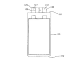
- FIG. 3 is a diagram illustrating a state where a tab member 125 is joined to the positive electrode pull-out tab 120 of the unit battery 100. It is a figure which shows the state which provided the hole in the positive electrode extraction tab and the negative electrode extraction tab for the serial connection of the unit battery 100.
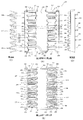
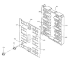
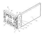
- FIG. It is a figure explaining the holder member 200 used when comprising the battery pack which concerns on embodiment of this invention. It is a perspective view of the holder member 200 used when comprising the battery pack which concerns on embodiment of this invention.
- FIG. 3 is a perspective view of a substrate 300 used in series connection of unit cells 100 in a battery pack according to an embodiment of the present invention.
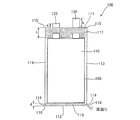
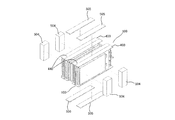
- FIG. 1 is a diagram showing a unit battery 100 constituting a battery pack according to an embodiment of the present invention.
- a lithium ion secondary unit battery that is charged and discharged by moving lithium ions between a negative electrode and a positive electrode is used.
- the battery main body 110 of the unit battery 100 has an electrode laminate in which a plurality of sheet-like positive electrodes and a plurality of sheet-like negative electrodes are laminated via separators, and an electrolyte solution (both not shown) are rectangular in a plan view. It has a structure accommodated in a laminate film exterior material. A positive electrode extraction tab 120 and a negative electrode extraction tab 130 are extracted from the first end 111 of the battery main body 110.
- the positive electrode pull-out tab 120 and the negative electrode pull-out tab 130 are both flat and are connected to the sheet-like positive electrode and the sheet-like negative electrode directly or via a lead body, respectively, in the laminate film exterior material.
- the laminate film exterior material is constituted by a metal laminate film having a heat-sealing resin layer on the surface that becomes the inside of the battery. More specifically, for example, two metal laminate films are laminated to form a laminate film exterior material, and an electrode laminate having a sheet-like positive electrode, a sheet-like negative electrode, and a separator and an electrolytic solution are accommodated therein.
- the outer periphery (first end 111, second end 112, two side ends 113) of the laminate film exterior material is heat-sealed, so that the inside is sealed.
- the metal piece drawn out from the battery body 110 made of the laminate film exterior material such as the positive electrode extraction tab 120 and the negative electrode extraction tab 130 will be referred to as a “drawer tab”, and a separator or an electrolysis will be provided inside the laminate film exterior material.
- a sheet-like positive electrode or a sheet-like negative electrode laminated via a liquid or the like is referred to as an “electrode”.
- the electrode laminate in addition to a laminate of a plurality of sheet-like positive electrodes and a plurality of sheet-like negative electrodes as described above, a laminate of a sheet-like positive electrode and a sheet-like negative electrode via a separator. The thing which makes a laminated body by winding this and compressing this is also contained.
- the material of the positive electrode pull-out tab 120 is aluminum or an aluminum alloy
- the material of the negative electrode pull-out tab 130 is nickel
- a material obtained by nickel plating other metals nickel plating.
- Materials such as nickel-plated copper) and nickel and other metal clads nickel clad materials such as nickel-copper clad are generally used.
- the unit cell 100 has a positive electrode extraction tab 120 containing aluminum and a negative electrode extraction tab 130 containing nickel.
- a positive electrode extraction tab 120 made of aluminum and a negative electrode extraction tab 130 made of nickel are used.
- the positive electrode pull-out tab 120 of the unit battery 100 and the negative electrode pull-out tab 130 of the unit battery 100 adjacent to the unit battery 100 are fixed by mechanically tightening them with bolts and nuts. And make electrical connections.
- the conductivity deteriorates after a predetermined period of time due to a potential difference problem. there's a possibility that.
- an additional tab 125 containing nickel is joined to the positive electrode lead tab 120 of the unit battery 100 by welding.
- the connection tab 125 of one unit cell 100 and the negative electrode pull-out tab 130 of the other unit cell 100 are connected to each other, thereby providing conductivity due to a potential difference problem. Solve the problem of deterioration.
- the positive electrode extraction tab 120 made of aluminum in the unit battery 100 has a length a from the first end portion 111, and the negative electrode extraction tab 130 made of nickel has a first end.
- the length from the portion 111 is b (b> a).
- an extension tab member 125 made of nickel is joined to the positive electrode lead tab 120 made of aluminum having a length a by ultrasonic welding so that the length from the first end portion 111 is b, It is added (see FIGS. 2 and 3).
- a hole 127 is provided in the additional tab member 125 as a positive electrode extraction tab, and a hole 137 is provided in the negative electrode extraction tab 130.
- the entire drawer tab formed by joining the additional tab members 125 may be referred to as a positive electrode drawer tab 120.
- the members including nickel are brought into contact with each other and pulled out. Since the tabs are mechanically connected to each other, the electrical connection portions of adjacent unit cells are electrically connected by the same kind of metal material, there is no problem of potential difference, and conductivity deterioration may occur over time. Almost disappear.
- FIG. 4A is a view of the holder member 200 seen from the first main surface side
- FIG. 4B is a holder view from the second main surface side. It is the figure which looked at the member 200
- 4C is a view showing a cross section XX ′ of FIG. 4A
- FIG. 4D is a view of the holder member 200 as seen from the side.
- the holder member 200 is a member made of synthetic resin, such as ABS, on which a first surface 210 and a second surface 250 having a front and back relationship with the first surface 210 are formed.
- first row 211 of the first surface 210 of the holder member 200 as shown in FIG. 4A, drawer tab insertion holes 215 are formed side by side from the top to the bottom.
- a pull-out tab insertion hole 215 is formed side by side from the top to the bottom.
- the drawer tab insertion hole 215 is a hole that penetrates from the first surface 210 side to the second surface 250 side, and is a hole through which the drawer tab of the unit battery 100 can be inserted.
- drawer tab guide ribs 203 are provided on the upper and lower sides of the first row 211 and the second row 212, respectively. Further, the pull-out tab routing portion 213 is sandwiched between the pull-out tab guide ribs 203 on the first row 211 side, and the pull-out tab routing portion 213 is sandwiched between the pull-out tab guide ribs 203 on the second row 212 side. A recess 214 is provided.
- the pull-out tabs of the unit cells 100 on the end side among the plurality of unit cells 100 connected in series are arranged from the first surface 210 side based on the restriction by the pull-out tab guide ribs 203.
- the two surfaces 250 are guided so as to pass through the pull-out tab routing portion 213.
- the drawer tabs of the unit cells 100 on the end side among the plurality of unit cells 100 connected in series are arranged on the first surface 210 side based on the regulation by the drawer tab guide ribs 203. From the first side to the second surface 250 side, it is guided so as to pass through the drawing tab drawing recess 214.
- the pull-out tab of the unit battery 100 that is not on the end side (the upper side and the lower side of the holder member 200 in FIG. 4A) is inserted into the pull-out tab insertion hole 215. In this manner, the holder member 200 is attached.
- the pull-out tab guide protrusion 220 is roughly constituted by a top portion 221 and two tapered side surfaces 222 connected to the top portion 221, and when the pull-out tab of the unit battery 100 is to be inserted into the pull-out tab insertion hole 215.
- the space between the two tapered side surfaces 222 is gradually narrowed, and attachment of the unit battery 100 to the holder member 200 is facilitated. For this reason, the work efficiency at the time of connecting the some unit battery 100 in series improves, and it can improve productivity.
- the plane sandwiched between the upper and lower two drawer tab guide protrusions 220 is such that when the drawer tab of the unit battery 100 is inserted into the drawer tab insertion hole 215, the first end 111 of the unit battery 100 abuts. It functions as an abutting portion 230 that regulates the position of the first end portion 111.
- the first end portion 111 of the unit battery 100 is brought into contact with the unit battery 100, whereby the unit battery 100 can be easily aligned in the stacking direction. Work efficiency at the site increases and productivity increases.
- the abutting portion 230 has a planar shape, but the abutting portion 230 is not necessarily limited to such a shape, and the first end 111 of the unit battery 100 is not limited. Any shape is possible as long as the position can be regulated.
- the position of the first end 111 of the unit battery 100 cannot be regulated by the abutting part 230 as described above.
- the unit cells 100 arranged at both ends can be aligned by applying the first end 111 to the pull-out tab guide rib 203.
- the surface of the drawer tab guide rib 203 with which the first end 111 abuts and the abutting portion 230 are provided on the same plane.
- the substrate 300 is attached to the second surface 250 of the holder member 200.
- the drawer tabs of the adjacent unit cells 100 are folded and connected to achieve conduction.
- a connecting member such as a bolt and nut
- a nut housing for housing the nut 256 for this purpose is provided.
- Six portions 255 are provided on the first row 211 side on the second surface 250 side and five on the second row 212 side.
- the alignment protrusions 263 are protrusions used for alignment when the substrate 300 is attached to the holder member 200, and are arranged one on each of the first row 211 side and the second row 212 side.
- the screw holes 270 used for fixing the substrate 300 and the holder member 200 after the substrate 300 is attached to the holder member 200 using the alignment protrusion 263 described above are provided on the first row 211 side. And one on each of the second row 212 side.
- a bolt and a nut are used as the connecting member is shown, but a connecting member such as a caulking pin or a rivet may be used instead of the bolt and the nut.
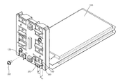
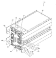
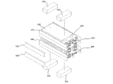
- FIG. 5 is a perspective view of a holder member 200 used in configuring the battery pack according to the embodiment of the present invention.
- Eight pull-out tab insertion holes 215 are provided in the first row 211 of the second surface 250 of the holder member 200, and eight pull-out tab insertion holes 215 in the second row 212, respectively.
- the structure between the two is integrally formed with the main body using the same resin as the main body, and this structure is referred to as a bridging structure portion 251.
- the bridging structure portion 251 is provided with a nut accommodating portion 255 for accommodating the nut 256.
- a bridging structure portion 251 is effective for strengthening the rigidity of the holder member 200, can provide a space for accommodating the nut 256, and can effectively utilize the space.
- a partition piece 260 disposed between the connecting portions of the drawer tabs is provided.
- Such a bridging structure portion 251 is effective for strengthening the rigidity of the holder member 200, and can provide a space for standing the partition piece 260, so that the space can be effectively used.
- an alignment projection 263 used for alignment between the substrate 300 and the holder member 200 is provided.
- Such a bridging structure portion 251 is effective for strengthening the rigidity of the holder member 200, and can provide a space for standing the alignment projection 263, so that the space can be effectively used.
- a screw hole 270 in which a board fixing screw 271 that fixes the board 300 and the holder member 200 is screwed is provided.
- Such a bridging structure portion 251 is effective for strengthening the rigidity of the holder member 200, and can provide a space for the screw hole 270, thereby effectively utilizing the space.
- FIG. 6 is a perspective view of a substrate 300 used in series connection of unit batteries 100 in the battery pack according to the embodiment of the present invention.
- the substrate 300 mainly composed of glass epoxy or the like is used by being attached to the second surface 250 side of the holder member 200, and the outer peripheral shape of the substrate 300 is the second surface 250 of the holder member 200.
- the outer peripheral shape substantially coincides with the outer peripheral shape.
- drawer tab drawing notches 314 are formed so as to correspond to the drawer tab drawing recesses 214 of the holder member 200.
- the substrate 300 is provided with a pull-out tab lead-out hole 315 so as to correspond to the pull-out tab insertion hole 215 of the holder member 200.
- the substrate 300 is provided with partition piece extraction holes 317 so as to correspond to the partition pieces 260 of the holder member 200.
- the substrate 300 is provided with drawer tab / partition piece extraction holes 316 corresponding to both the drawer tab insertion holes 215 and the partition pieces 260 of the holder member 200. Each of these holes is a hole penetrating from one main surface of the substrate 300 to the other main surface, and is configured such that a drawer tab of the unit battery 100, a partition piece 260, and the like can be inserted.
- the thin film electrode part 320a, the thin film electrode part 320b, and the thin film electrode part 320c are provided in the place where the drawer tab of the unit battery 100 is fixed to the substrate 300 by the connecting member.
- the connecting member is preferable because the combination of the bolt and the nut is simple and can realize a strong connection, but a connecting member such as a caulking pin or a rivet may be used instead of the bolt and the nut.
- the thin film electrode portion 320 a is electrically connected to the metal positive electrode washer 321 fixed on the substrate 300, and the thin film electrode portion 320 c is connected to the metal negative electrode washer fixed on the substrate 300. Conduction with 322 is achieved.
- the positive electrode washer 321 and the negative electrode washer 322 are connected to the pull-out tab at the end of the unit battery 100 connected in series, so that the positive electrode washer 321 and the negative electrode washer 322 are battery packs. It will be used as a terminal for charging and discharging power.
- the thin film electrode part 320 b is electrically connected to a terminal part (not shown) of the connector 340, and the potential for monitoring each unit battery 100 can be measured via the connector 340.
- the connector 340 can also be configured such that a signal from a temperature measurement sensor (not shown) that measures the temperature of the unit battery 100 can be taken out.
- each of the thin film electrode portion 320a, the thin film electrode portion 320b, and the thin film electrode portion 320c is provided with a drawer tab connection screw hole 325 through which a drawer tab connection bolt 257 used for fixing the drawer tab of the unit battery 100 is inserted. It has been.
- the thin film electrode part 320a and the thin film electrode part 320c one drawer tab of the unit battery 100 at the end of the unit batteries 100 connected in series is fixed.
- two thin film electrode portions 320b are fixed so that the pull-out tabs of adjacent unit cells 100 are folded.
- the substrate fixing screw hole 329 formed in the substrate 300 is a hole through which the substrate fixing screw 271 used for fixing the holder member 200 and the substrate 300 is inserted.
- the drawer tab is firmly fixed from both sides of the substrate 300 by connecting members such as bolts and nuts, and the drawer tab guide protrusion 220 on the surface opposite to the surface to which the tab of the substrate 300 is fixed.
- connecting members such as bolts and nuts
- the drawer tab guide protrusion 220 on the surface opposite to the surface to which the tab of the substrate 300 is fixed.
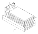
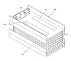
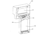
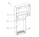
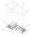
- FIG. 7 is a view for explaining a battery protection member 400 used in configuring the battery pack according to the embodiment of the present invention.
- FIG. 7A is a flat plate portion 410 to which the main surface of the unit battery 100 is attached.
- FIG. 7B is a view of the battery protection member 400 as viewed from the upper side of FIG. 7A.
- the battery protection member 400 is a member formed of, for example, a synthetic resin such as ABS, and is used so as to be inserted between the stacked unit cells 100 when the unit cells 100 are stacked.
- the flat plate portion 410 of the battery protection member 400 is a member that is sandwiched between the unit battery 100 and the unit battery 100 connected in series therewith.
- the protect side plate portion 440 is provided so as to extend from both ends of the flat plate portion 410 in a direction perpendicular to the flat plate portion 410. Therefore, as shown in FIG. 7B, the battery protection member 400 is a member having an H-shaped cross section.
- the flat plate 410 has a first notch 421 that is the deepest notch and both sides of the first notch 421, and a second notch that is deeper than the first notch 421.
- a notch portion 420 is configured that includes a notch portion 422 and a third notch portion 423 that is the shallowest notch portion disposed on both sides of the second notch portion 422.
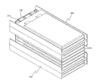
- FIGS. 8 to 18 are views for explaining a manufacturing process of the battery connection structure 500 constituting the battery pack according to the embodiment of the present invention.
- the nuts 256 are attached to all the nut accommodating portions 255 provided on the second surface 250 of the holder member 200.
- the inner circumference of the nut accommodating portion 255 is set to such a size that the nut 256 cannot be easily removed when the nut 256 is fitted into the nut accommodating portion 255.
- the positioning of the holder member 200 and the substrate 300 is performed by inserting the alignment protrusion 263 of the holder member 200 into the alignment hole 328 of the substrate 300.
- the two board fixing screws 271 are inserted into the board fixing screw holes 329 and screwed into the screw holes 270, so that the holder member 200 and the board 300 are fixed.
- various types of screws can be used as the board fixing screw holes 329.
- the use of tapping screws improves the working efficiency during manufacturing.
- the unit battery 100 is disposed on the first surface 210 of the holder member 200.
- the alignment at this time is performed by abutting the first end 111 of the unit battery 100 against the pull-out tab guide rib 203.
- the negative electrode lead tab 130 of the unit battery 100 is bent so as to contact the thin film electrode part 320 b of the substrate 300 using the lead tab drawing recess 214.
- the positive electrode pull-out tab 120 of the unit battery 100 is bent so as to contact the thin film electrode portion 320 a of the substrate 300 using the pull-out tab lead-out portion 213, and the pull-out tab connection bolt 257 is inserted into the hole of the positive electrode pull-out tab 120.
- the drawer tab connection screw hole 325 is inserted, and the drawer tab connection bolt 257 and the nut 256 accommodated in the nut accommodating portion 255 are screwed together. Thereby, the attachment of the first unit battery 100 is completed.
- the work is performed on the first surface 210 side of the holder member 200.
- two double-sided adhesive tapes 460 are attached to the upper main surface of the unit battery 100 as shown in the drawing.
- the double-sided adhesive tape 460 is used for fixing between the unit battery 100 that is first attached to the holder member 200 and the unit battery 100 that is secondly attached to the holder member 200.
- the double-sided adhesive tape 460 is provided on the main surface of the unit battery 100 as shown in the figure because a spacer described later is arranged between the two double-sided adhesive tapes 460 to increase productivity. is there.
- a spacer (not shown) having a thickness equal to or larger than the thickness of the double-sided adhesive tape 460 is disposed on the unit battery 100 attached first, and further, the spacer is placed on the spacer.
- the two drawer tabs of the second unit battery 100 are inserted into the drawer tab insertion holes 215 so as to slide.
- the pull-out tab guide protrusions 220 are arranged above and below the two pull-out tab insertion holes 215. Further, since the pull-out tab guide protrusions 220 are provided with tapered side surfaces 222, The space between the pull-out tab guide protrusions 220 is gradually narrowed. Thereby, the drawer tab of the unit battery 100 can be easily guided to the drawer tab insertion hole 215 of the holder member 200.
- the abutting portion 230 between the upper and lower drawer tab guide protrusions 220 is configured such that when the drawer tabs (120, 130) of the unit battery 100 are inserted into the drawer tab insertion holes 215, the first end of the unit battery 100 is formed.
- the part 111 contacts and regulates the position of the first end part 111. Since the holder member 200 is provided with such an abutting portion 230, the unit battery 100 can be easily aligned in the stacking direction by bringing the first end portion 111 of the unit battery 100 into contact therewith. This can be performed, and the work efficiency in manufacturing the battery bag is increased, and the productivity is improved.
- the first end unit 111 is brought into contact with the abutting unit 230 and the spacer is removed, so that the unit battery 100 attached first and the unit battery 100 attached second are obtained. Bonding is performed using a double-sided adhesive tape 460.
- two double-sided adhesive tapes 460 are attached to the main surface of the unit battery 100 so that the unit batteries 100 are joined to each other so as to impart vibration resistance to the battery pack.
- conditions suitable for this purpose will be described below.
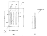
- FIG. 27 is a diagram for explaining the bonding conditions between the unit cells 100.
- FIG. FIG. 27A is a diagram showing dimensions of the unit battery 100 used in the battery pack according to the present embodiment
- FIG. 27B is used for bonding the unit battery 100 used in the battery pack according to the present embodiment. It is a figure which shows the dimension of the double-sided adhesive tape 460.
- FIG. 27A is a diagram showing dimensions of the unit battery 100 used in the battery pack according to the present embodiment
- FIG. 27B is used for bonding the unit battery 100 used in the battery pack according to the present embodiment. It is a figure which shows the dimension of the double-sided adhesive tape 460.
- the unit battery 100 includes a first end 111 having a length of 82 mm, a side end 113 having a length of 150 mm, and chamfered portions 119 formed at both corners of the second end 112.
- the outer peripheral length is 459 mm.
- an electrode stack region 105 in the unit battery 100 is defined.
- the electrode laminated region 105 is a region corresponding to a location where an electrode laminated body including a sheet-like positive electrode, a sheet-like negative electrode, and a separator, which are sealed in the unit battery 100, in the laminate film exterior material. That is, the electrode lamination region 105 is a main plane region corresponding to a location where the laminate film exterior material swells by accommodating the electrode laminate.
- the electrode lamination region 105 has a substantially rectangular shape, but its long side is 131 mm, its short side is 69 mm, and the electrode lamination region 105 has an outer peripheral length of 400 mm.
- the dimensions of the double-sided adhesive tape 460 used for bonding the unit batteries 100 are 100 mm for the long side and 12 mm for the short side,
- the outer peripheral length of one double-sided adhesive tape 460 is 224 mm.
- the total outer peripheral length of the double-sided adhesive tape 460 used for joining the batteries is 448 mm.
- the total outer peripheral length of the double-sided adhesive tape 460 is set to be longer than the outer peripheral length of the electrode laminated region 105 which is a region corresponding to the location where the electrode laminated body is accommodated in the laminate film exterior material. There is a point. When a vibration test was performed with such settings, good results could be obtained.
- the total outer peripheral length of the double-sided adhesive tape 460 is the region of the electrode laminated region 105 which is a region corresponding to the accommodation location of the electrode laminated body in the laminated film exterior material of the unit battery 100. Since it is set to be longer than the outer peripheral length, even if vibration is applied, the unit cells are not separated from each other, and stress is not applied to the connecting portion between the drawer tabs, so that reliability is improved. It can be done. In addition, since the stresses generated at the ends of the double-sided adhesive tape can be dispersed as compared with the case where the batteries are bonded most strongly, that is, compared with the case where the entire surface corresponding to the accommodation location of the electrode laminate is bonded. Even if vibration is applied to the pack, the laminate film exterior material can be hardly damaged.
- the total outer peripheral length of the double-sided adhesive tape 460 is the laminate film of the unit battery 100.
- the shape of the double-sided adhesive tape 460 is not limited to this as long as it is set to be longer than the outer peripheral length of the electrode laminated region 105 in the exterior material. For example, by providing a plurality of circular patch-like double-sided adhesive tapes, it is possible to increase the total outer peripheral length, satisfy the above conditions, and improve the manufacturability.
- other shape examples of the double-sided adhesive tape 460 will be described.
- FIG. 28 is a diagram for explaining another example of the bonding condition between the unit cells 100.
- FIG. 28A is a diagram showing dimensions of the unit battery 100 used in the battery pack according to the present embodiment
- FIG. 28B is used for bonding the unit battery 100 used in the battery pack according to the present embodiment. It is a figure which shows the dimension of the double-sided adhesive tape 460.
- FIG. The dimensions of the unit battery 100 itself are the same as those shown in FIG.
- the double-sided adhesive tape 460 used for bonding the unit batteries 100 has a long side length of 100 mm and a short side length of 6 mm.
- the outer peripheral length of the double-sided adhesive tape 460 is 212 mm.
- the total outer peripheral length of the double-sided adhesive tape 460 used for joining the batteries is 636 mm, and can be set longer than the outer peripheral length 400 mm of the electrode lamination region 105. .
- the same effect as that of the previous embodiment can be obtained also by the bonding condition as shown in FIG.
- FIG. 29 is a diagram for explaining another example of the bonding condition between the unit cells 100.
- FIG. FIG. 29A is a diagram showing dimensions of the unit battery 100 used in the battery pack according to the present embodiment
- FIG. 29B is used for bonding the unit battery 100 used in the battery pack according to the present embodiment. It is a figure which shows the dimension of the double-sided adhesive tape 460.
- FIG. The dimensions of the unit battery 100 itself are the same as those shown in FIG.
- the double-sided adhesive tape 460 used for bonding the unit batteries 100 is a circular shape having a diameter of 30 mm, and the outer peripheral length is about 94.2 mm. is there.
- the total outer peripheral length of the double-sided adhesive tape 460 used for joining the batteries is 565.2 mm, and the outer peripheral length of the electrode lamination region 105 is 400 mm. It can be set longer. As described above, the same effect as that of the previous embodiment can be obtained also by the bonding condition as shown in FIG.
- the adhesive strength of the double-sided tape 460 used in this embodiment is 0.98 N / mm
- two strips of double-sided tape 460 having a long side length of 100 mm and a short side length of 12 mm are used. Accordingly, the bonding strength (tensile strength) between the unit cells 100 in the long side direction and the short side direction is as follows.
- Long side direction: 0.98 (N / mm) ⁇ 12 (mm) ⁇ 2 (pieces) 24N
- Short side direction: 0.98 (N / mm) ⁇ 100 (mm) ⁇ 2 (pieces) 98N
- the adhesive strength of the fused part of the laminate film exterior material of the unit battery 100 is 1.5 N / mm. In the unit battery 100 shown in FIG.
- the narrowest width fused portion is 5 mm.
- the minimum bonding strength of the fused portion of the laminated film exterior material of the unit battery 100 is as follows in the long side direction and the short side direction.
- Long side direction: 1.5 (N / mm) ⁇ 5 (mm) ⁇ 2 (side) 15N
- Short side direction: 1.5 (N / mm) ⁇ 5 (mm) ⁇ 2 (pieces) 15N
- melting part of the laminate film exterior material of the unit battery 100 is as follows in a long side direction and a short side direction.
- the bonding strength between the unit cells 100 by the double-sided adhesive tape 460 is set to be larger than the minimum bonding strength of the fused portion. According to this, when the battery pack is disassembled and the unit battery 100 is taken out, the unit battery 100 becomes unusable because the fused portion of the unit battery 100 is peeled off. The risk of being reused can be prevented.
- the positive electrode extraction tab 120 of the unit battery 100 that is first attached to the holder member 200 is arranged on the first row 211 side, and the negative electrode extraction tab 130 is arranged on the second row 212 side.
- the unit cell 100 that is second attached to the holder member 200 is arranged such that the positive electrode extraction tab 120 is on the second row 212 side and the negative electrode extraction tab 130 is on the first row 211 side.
- the positive lead tabs 120 of the odd-numbered unit cells 100 are arranged on the first row 211 side, and the negative lead tabs 130 are arranged on the second row 212 side.
- the positive lead tabs 120 of the unit cells 100 that are evenly attached are arranged on the second row 212 side, and the negative lead tabs 130 are arranged on the first row 211 side.
- the orientation of the pull-out tabs of the adjacent unit cells 100 is different in the stacking direction, it is not necessary to make an oblique connection in the stacking direction on the substrate 300 side.
- the positive electrode pull-out tab 120 of the unit battery 100 attached second is bent downward in the figure and overlapped with the negative electrode pull-out tab 130 of the unit battery 100 attached first. .
- the drawer tab connection bolt 257 is inserted into the hole / drawer tab connection screw hole 325 of each drawer tab, and the drawer tab connection bolt 257 and the nut 256 are screwed together to form the thin film electrode portion 320b.
- a connection portion between the negative electrode pull-out tab 130 of the unit battery 100 attached first and the positive electrode pull-out tab 120 of the unit battery 100 attached second is formed, and the electrical connection is completed.
- the negative electrode pull-out tab 130 of the unit battery 100 attached second is bent upward in the drawing to prepare for connection with the positive electrode pull-out tab 120 of the unit battery 100 attached third.
- the battery protection member 400 is attached using a spacer in the same manner as when the second unit battery 100 is attached.
- the upper surface of the second unit battery 100 and the lower surface of the battery protection member 400 are attached by two double-sided adhesive tapes 460.
- two double-sided adhesive tapes 460 are attached to the upper surface of the battery protection member 400. With this double-sided adhesive tape 460, the battery protection member 400 and the unit battery 100 that is thirdly attached to the holder member 200 are joined.
- the battery protection member 400 is attached to the unit battery 100 with a gap of about 2 mm between the second notch 422 or the third notch 423 and the holder member 200. This gap makes it difficult for vibrations and shocks applied to the battery pack to be transmitted to the positive electrode extraction tab 120 and the negative electrode extraction tab 130, thereby improving the reliability of the electrical connection of the battery pack.
- the battery protection member 400 can be attached to the unit battery 100 in a state where the battery protection member 400 is pushed in until the second notch 422 or the third notch 423 hits the holder member 200. By attaching in this way, the battery protective member 400 can be easily aligned in the stacking direction.
- FIG. 15 shows a state in which the third unit battery 100 to the eighth unit battery 100 are sequentially attached to the holder member 200 and the substrate 300 by the same method as described above.
- the drawer tab is folded, and the drawer tab connection bolts 257 are used to connect the drawer tabs of adjacent unit cells 100 to make electrical connection. Go.
- the process shown in FIG. 16 shows a state where the battery protection member 400 is further attached after the eighth unit battery 100 is attached.
- the two battery protection members 400 are arranged, thereby protecting each unit battery 100 from an external impact or the like. .
- FIG. 17 shows a state where the ninth unit battery 100 and the tenth unit battery 100 are further attached to the holder member 200 and the substrate 300 on the battery protection member 400.
- the negative electrode pull-out tab 130 of the tenth unit cell 100 is bent using the pull-out tab lead-out portion 213 so as to contact the thin-film electrode portion 320c of the substrate 300, and the thin-film electrode portion by the pull-out tab connection bolt 257. It adheres to 320c. Accordingly, the drawer tabs of the first to tenth unit cells 100 are connected on the substrate 300, and the series connection of the ten unit cells 100 is completed. Charging / discharging the ten unit cells 100 connected in series can be performed using the electrode washer 321 for positive electrode and the electrode washer 322 for negative electrode. A terminal member 331 is attached to the positive electrode washer 321, and a terminal member 332 is attached to the negative electrode washer 322, thereby completing the battery connection structure 500.
- the operation of inserting the positive electrode pull-out tab and the negative electrode pull-out tab of the plurality of unit batteries 100 into the pull-out tab insertion hole 215 of the holder member 200 is performed. Since the drawer tabs having different polarities of the battery 100 are connected to each other on the substrate 300, the work efficiency in manufacturing the battery bag is high, and the productivity is improved.
- the plurality of unit cells 100 are configured such that the drawer tabs having different polarities are coupled to each other on the substrate 300 by the drawer tab connection bolts 257 and nuts 256, the plurality of unit cells 100 can be easily electrically connected. This increases the work efficiency in manufacturing the battery pack and improves the productivity.
- the substrate 300 is provided with a thin film electrode part 320a, a thin film electrode part 320b, and a thin film electrode part 320c as three kinds of thin film electrode parts.
- the thin-film electrode part 320 a conducts the positive electrode washer 321 provided at one end of the substrate 300 and the positive electrode extraction tab 120 of the unit cell 100 attached to one end of the substrate 300. Used to connect. That is, the connecting portion in the thin film electrode portion 320a functions as a positive electrode lead tab-positive electrode washer connecting portion.
- the unit battery 100 attached to one end of the substrate 300 is bent in the same direction in both the positive electrode extraction tab 120 and the negative electrode extraction tab 130 as can be seen by referring to the bending direction b 1 in FIG. It is supposed to be.
- the thin film electrode portion 320c includes a negative electrode washer 322 provided at the other end different from the one end of the substrate 300, and a negative electrode lead tab 130 of the unit cell 100 attached to the other end of the substrate 300. Is used for conductive connection. That is, the connecting portion in the thin film electrode portion 320a functions as a negative electrode extraction tab-negative electrode washer connecting portion.
- the unit battery 100 is attached to the other end of the substrate 300 also, as can be seen with reference to such direction b 2 folded in FIG. 18, from its cathode pulled-out tab 120 and the anode lead-out tab 130, folded together in the same direction It is supposed to be.
- the thin-film electrode part 320b is used to conductively connect the positive electrode extraction tab 120 of one unit cell 100 and the negative electrode extraction tab 130 of the other unit cell 100 that are not attached to both ends of the substrate 300. . That is, the connection part in the thin film electrode part 320b functions as a pull-out tab connection part that connects the pull-out tabs of the plurality of unit cells 100 having different polarities.
- the unit battery 100 that is not attached to both ends of the substrate 300 and to which the drawer tab is coupled by the drawer tab coupling portion can be understood by referring to the bending directions b 1 and b 2 in FIG.
- the positive electrode extraction tab 120 and the negative electrode extraction tab 130 are bent in opposite directions.
- the height h 1 of the partition piece 260 from the substrate 300 is a pull-out tab used for connecting the pull-out tabs (120, 130) in the connection portion of the pull-out tabs (120, 130).
- the connection bolt 257 is configured to be higher than the height h 2 .
- Such a dimensional relationship is established not only at the positions shown in FIG. 13 but also at the heights of all the partition pieces 260 and the heights of the pull-out tab connection bolts 257 at all the connecting portions.
- the drawer tabs (120, 130) of the unit battery 100 are inserted through the drawer tab insertion holes 215 and attached, and the drawer tabs (120, 130) are bent on the substrate 300 side.
- the partition piece 260 since the partition piece 260 is present, there is no possibility of making a manufacturing error that causes the drawer tabs (120, 130) to be bent in a direction opposite to the direction in which the drawer tabs should be bent.
- the tabs may extend over the partition piece 260 and reach the connecting portion that is not the original connecting portion.
- the lengths of the drawer tabs (120, 130) and the height of the partitioning pieces 260 are defined so as to be impossible, so that unintentional conduction can be avoided.
- the discharge terminal mounting recess 611 and the charge terminal mounting recess 612 provided in the first case body 600 are used for the first case body 600 for housing the battery connection structure 500. Then, the discharge terminal 613 and the charge terminal 614 are screwed.
- the first buffer member 621 is attached to the second housing portion 602 of the first case body 600, and the second buffer member 622 is attached to the circuit housing portion 603 with an adhesive or the like.
- the third buffer member 663 is attached to the second housing portion 662 of the second case body 660 with an adhesive or the like.
- FIG.22 and FIG.23 performs the process of attaching a shock absorbing material with respect to the battery connection structure 500.
- FIG. In the battery pack according to the present invention, the first battery connection structure 500 and the second battery connection structure 500 are configured to be accommodated in the battery pack. The first battery connection structure 500 and the second battery connection structure 500 are used in parallel connection.
- a thick fourth buffer member 504 is attached to the unit battery 100 at the end with respect to the first battery connection structure 500, and the fourth buffer member 504 is attached to all the protect side plates.
- a thinner fifth buffer member 505 is attached.
- An adhesive or the like is used when attaching the fourth buffer member 504 and the fifth buffer member 505 to each part.
- the thermistor 530 (not shown in FIG. 22) of the temperature detection means in the battery pack is attached only to the first battery connection structure 500. The thermistor 530 detects the temperature of the first battery connection structure 500 and transmits the detection signal to the protection circuit board 700.
- the fourth buffer member 504 is attached to the unit battery 100 at the end with respect to the second battery connection structure 500, and the fifth buffer member is provided only on the protect side plate portion on one side. 505 is attached.
- an adhesive or the like is used when attaching the fourth buffer member 504 and the fifth buffer member 505 to each part.
- the discharge terminal 613, the charge terminal 614, the thermistor 530, and the protection circuit board 700 are connected, and the protection circuit board 700 is screwed to the circuit housing portion 603 of the first case body 600.
- the first and second battery connection structures 500 and the protection circuit board 700 are connected, and the first and second battery connection structures are connected to the first housing portion 601 of the first case body 600.
- the second battery connection structure 500 is housed in the body 500 and the second housing portion 602, respectively.
- the first case body 600 and the second case body 660 are screwed together to complete the battery pack 800 according to the present invention.
- the temperature detection means in the battery pack 800 according to the present invention will be described.
- the battery pack 800 according to the present invention is configured by housing two battery connection structures 500 in the same case bodies 600 and 660, as shown in FIG.
- the thermistor 530 is provided only in the first battery connection structure 500 housed in the first housing portion of the case body, and temperature data detected here. Is transmitted to a circuit provided on the protection circuit board 700 and used for battery control.
- FIG. 30 is a view showing a posture when the battery pack 800 according to the embodiment of the present invention is used as a power source of a bicycle.
- the thermistor 530 is attached to the first battery connection structure 500, which is disposed vertically above the case body, is more easily heated, and is in a thermally disadvantageous condition. Temperature data is acquired from the thermistor 530, and the protection circuit board 700 controls discharge stop and the like based on the temperature data. According to such a battery pack 800 according to the present invention, the number of components can be reduced, the cost can be reduced, and the circuit configuration for processing the detection data of the thermistor 530 is simplified.
- the thermistor 530 is provided in the battery connection structure 500 that is vertically above the two battery connection structures 500 provided in the case body.
- the battery connection provided in the case body is used.
- the present invention can be applied even when there are three or more structures 500. That is, in the case of three or more battery connection structures 500 accommodated in the case body of the battery pack, the thermistor 530 is provided only in the battery connection structure 500 that is disposed at the uppermost position when used. To do.
- the vibration resistance of the battery pack 800 configured as described above will be described.
- the corners of the laminate film exterior material of the unit cell are laminated to the adjacent unit cell when subjected to vibration.
- the battery pack breaks down, leaks out the electrolyte solution and the like, and the battery pack breaks down.
- the battery body 110 is sealed by heat-sealing the outer periphery of the laminate film exterior material in a state in which the electrode laminate having the sheet-like positive electrode, the sheet-like negative electrode, and the separator and the electrolytic solution are housed inside. Has been.
- a positive electrode extraction tab 120 and a negative electrode extraction tab 130 are extracted from the first end 111 side in the outer periphery.
- the fused portion indicated by c formed on the first end 111 side is the first fused portion 117
- the fused portion indicated by d formed on the second end 112 side is the second. This is defined as a fused portion 118. All the fused portions are indicated by oblique lines in the figure. Further, the fusion weld lengths of the first fusion part 117 and the second fusion part 118 are both defined by the length in the pull-out direction of the tab.
- the second fusion length d of the second fusion part 118 is set shorter than the first fusion length c of the first fusion part 117.
- the probability that the first fusion part 117 is torn is extremely high.
- the probability that the second fusion part 118 is broken becomes large to some extent.
- chamfering is performed on the two second end side corner portions 116 in the second end portion 112, and chamfered portions 119 are formed at both corner portions. Accordingly, even when vibration is applied to the battery pack 800, the second end side corner portion 116 in which the chamfered portion 119 is formed does not affect the second fused portion 118 of the adjacent unit battery 100. The leakage of the electrolyte does not occur and the reliability can be improved.
- the first end portion 111 is rubbed against the first end corner portion 115 of the laminated film exterior material of the adjacent unit battery 100 due to vibration applied to the battery pack 800, the first fusion portion Since the probability that 117 is broken is very low, an increase in the number of manufacturing steps is suppressed without forming chamfers at the two first end corners 115 on the first end 111 side.
- the first fusion welding length c is 19 ⁇ 1 mm
- the second fusion welding length d is 6 ⁇ 1 mm.
- “ ⁇ 1 mm” is a manufacturing error.
- the dimensions of the fusion welding length as described above are determined on the basis of the following.
- the fusion width is desirably 5 mm or more in order to ensure the sealing property of the laminate film exterior material.
- the second welding length d which is the welding width in the second fusion part 118 is set to 6 ⁇ 1 mm in consideration of manufacturing tolerances and the like while giving a margin.
- the first fusion welding length c which is the fusion welding width in the first fusion part 117
- the first end side corner 115 of the adjacent unit battery 100 hits. Even if it is rubbed, the probability that the first fusion part 117 is broken can be made extremely low, and the reliability of the battery pack can be improved. Therefore, in the unit battery 100 according to the present embodiment, the first fusion welding length c is set to 19 ⁇ 1 mm in consideration of manufacturing tolerances and the like while giving a margin.
- c / d is a value obtained by dividing the first fusion welding length c by the second fusion welding length d.
- c / d (19 ⁇ 1) / (6 ⁇ 1). Since this c / d value is preferably a predetermined value or more than the worst condition value, it is preferable that c / d ⁇ (19 ⁇ 1) / (6 + 1) ⁇ 2.5. That is, in the battery pack according to the present invention, it is preferable that the c / d value obtained by dividing the first fusion welding length c by the second fusion welding length d is 2.5 or more.
- the battery pack 800 according to the present invention as described above has a configuration in which the chamfered portions 119 are provided at both corners on the second end portion 112 side where the fusion welding length is short, and an increase in the manufacturing process is suppressed at the manufacturing stage.
- the laminated film of the adjacent unit battery 100 is not pierced, and no leakage of the electrolyte occurs, so that the reliability can be improved. is there.
- the chamfered portion 119 is formed by cutting it into a straight line.
- the chamfered portion 119 having R may be formed by cutting the end-side corner portion 116 into an arc shape.
- the present invention is not limited to such a unit battery 100, and the laminate film exterior is provided.
- the present invention can also be applied to a material in which fused portions are provided on three sides of the material.
- Such a unit battery 100 will be described with reference to FIG.
- FIG. 31 is a diagram showing another example of the unit battery 100 constituting the battery pack 800.
- the battery main body 110 of the unit battery 100 shown in FIG. 31 includes an electrode laminate in which a plurality of sheet-like positive electrodes and a plurality of sheet-like negative electrodes are laminated via a separator, and an electrolyte solution (both not shown) are laminated.
- the laminated film exterior material is folded at the second end 112 and is welded on a total of three sides of the first end 111 and the two side ends 113.
- the electrode laminate and the electrolytic solution are enclosed in the laminate film exterior material.
- the two second end corners 116 at the second end 112 are chamfered, and the chamfered portions 119 are formed at both corners. You can enjoy the same effect.
- a battery pack in which a plurality of unit batteries 100 each having a laminated exterior member provided with a chamfered portion 119 at the corner portion 116 are connected in series can also enjoy the same effect as the above case.
- the second end side corner portion 116 in which the chamfered portion 119 is formed does not affect the adjacent unit battery 100, and the electrolyte leaks out.
- a highly reliable battery pack 800 can be provided.
- the present invention relates to a secondary battery pack such as a lithium ion battery whose use is rapidly expanding in the field of power storage devices for mobile objects in recent years. Since the unit battery constituting such a battery pack is difficult to handle, it is preferable that the battery pack is disassembled by the user and the unit battery is taken out and reused is avoided.
- the bonding strength between the unit cells by the double-sided adhesive tape is larger than the minimum bonding strength of the fused portion of the laminate film exterior material, so when disassembling the battery pack and taking out the unit cell, Since the unit battery becomes unusable by peeling off the fused part of the unit battery, the risk of reuse of the taken out unit battery can be prevented, and industrial applicability is very large.
- DESCRIPTION OF SYMBOLS 100 ... Unit battery, 105 ... Electrode lamination
- Battery connection structure 504 ... Fourth buffer member (thickness), 505 ... Fifth buffer member (thin), 530 ..Thermistor, 600... First case body, 601... First housing portion, 602... Second housing portion, 603... Circuit housing portion, 611. ⁇ charging terminal mounting recess, 613 ⁇ discharge terminal, 614 ⁇ charging terminal, 621 ⁇ first buffer member, 622 ⁇ second buffer member, 660 ⁇ second case body, 661 .. First housing part, 662... Second housing part, 663... Third buffer member, 67 3 ... Circuit housing part, 700 ... Protection circuit board, 800 ... Battery pack
Landscapes
- Chemical & Material Sciences (AREA)
- Chemical Kinetics & Catalysis (AREA)
- Electrochemistry (AREA)
- General Chemical & Material Sciences (AREA)
- Engineering & Computer Science (AREA)
- Manufacturing & Machinery (AREA)
- Battery Mounting, Suspending (AREA)
- Connection Of Batteries Or Terminals (AREA)
Abstract
Afin de fournir un bloc-batterie dans lequel des mesures ont été réalisées pour empêcher une utilisation répétée des unités de piles en infligeant un dommage aux batteries lors du retrait du bloc-batterie, ce qui rend les piles inutilisables, ce bloc-batterie comprend des unités de piles (100) qui sont collées ensemble en une pluralité de couches en utilisant une bande adhésive double face (460), ces unités de piles (100) possédant un matériau de revêtement de film laminé qui est formé à partir des parties fusionnées qui scellent ensemble une solution d'électrolyte et un laminé d'électrodes comprenant une feuille d'électrode positive, une feuille d'électrode négative et un séparateur. Le bloc-batterie est caractérisé en ce que la force de liaison entre les unités de piles (100) collées au moyen de la bande adhésive double face (460) est plus importante que la force de liaison minimale des parties fusionnées.
Priority Applications (3)
| Application Number | Priority Date | Filing Date | Title |
|---|---|---|---|
| US14/008,417 US20140045027A1 (en) | 2011-03-31 | 2011-09-07 | Battery pack |
| EP11862421.2A EP2693517B1 (fr) | 2011-03-31 | 2011-09-07 | Bloc-batterie |
| CN201180069788.6A CN103460439B (zh) | 2011-03-31 | 2011-09-07 | 电池组 |
Applications Claiming Priority (2)
| Application Number | Priority Date | Filing Date | Title |
|---|---|---|---|
| JP2011-078343 | 2011-03-31 | ||
| JP2011078343A JP5831924B2 (ja) | 2011-03-31 | 2011-03-31 | 電池パック |
Publications (1)
| Publication Number | Publication Date |
|---|---|
| WO2012131804A1 true WO2012131804A1 (fr) | 2012-10-04 |
Family
ID=46929650
Family Applications (1)
| Application Number | Title | Priority Date | Filing Date |
|---|---|---|---|
| PCT/JP2011/005034 WO2012131804A1 (fr) | 2011-03-31 | 2011-09-07 | Bloc-batterie |
Country Status (5)
| Country | Link |
|---|---|
| US (1) | US20140045027A1 (fr) |
| EP (1) | EP2693517B1 (fr) |
| JP (1) | JP5831924B2 (fr) |
| CN (2) | CN105405989B (fr) |
| WO (1) | WO2012131804A1 (fr) |
Cited By (1)
| Publication number | Priority date | Publication date | Assignee | Title |
|---|---|---|---|---|
| CN113972350A (zh) * | 2020-07-22 | 2022-01-25 | 丰田自动车株式会社 | 组电池 |
Families Citing this family (11)
| Publication number | Priority date | Publication date | Assignee | Title |
|---|---|---|---|---|
| JP6209348B2 (ja) * | 2013-03-29 | 2017-10-04 | Fdk株式会社 | 電気化学デバイスの製造方法 |
| WO2015182050A1 (fr) * | 2014-05-30 | 2015-12-03 | シャープ株式会社 | Dispositif mobile |
| US10497909B2 (en) * | 2014-09-05 | 2019-12-03 | Ford Global Technologies, Llc | Battery assembly with snap-in arrays |
| US10403869B2 (en) | 2015-04-13 | 2019-09-03 | Cps Technology Holdings, Llc | Adhesive tape for positioning battery cells in a battery module |
| KR101977639B1 (ko) * | 2016-02-16 | 2019-05-14 | 주식회사 엘지화학 | 전극조립체 및 그의 제조방법 |
| KR102473336B1 (ko) * | 2019-10-07 | 2022-12-01 | 주식회사 엘지에너지솔루션 | 전지 모듈 및 이를 포함하는 전지팩 |
| KR102464825B1 (ko) * | 2019-10-10 | 2022-11-07 | 주식회사 엘지에너지솔루션 | 전지 모듈 및 이를 포함하는 전지팩 |
| KR20210056824A (ko) * | 2019-11-11 | 2021-05-20 | 주식회사 엘지화학 | 배터리 모듈, 이러한 배터리 모듈을 포함하는 배터리 팩 및 자동차 |
| GB202106414D0 (en) * | 2021-05-05 | 2021-06-16 | Aceleron Ltd | Battery |
| CN113314812A (zh) * | 2021-06-25 | 2021-08-27 | 东莞新能安科技有限公司 | 电池组及用电设备 |
| CN117139328B (zh) * | 2023-10-31 | 2024-02-06 | 中创新航科技集团股份有限公司 | 一种电芯拆解方法及装置 |
Citations (4)
| Publication number | Priority date | Publication date | Assignee | Title |
|---|---|---|---|---|
| JP2008153204A (ja) * | 2006-11-21 | 2008-07-03 | Hitachi Vehicle Energy Ltd | 二次電池モジュール |
| WO2008102571A1 (fr) * | 2007-02-21 | 2008-08-28 | Nec Corporation | Batterie conditionnée, ensemble de batterie empilé, et batterie recouverte d'un film |
| JP2009259581A (ja) * | 2008-04-16 | 2009-11-05 | Nec Tokin Corp | 電池モジュール |
| JP2010170799A (ja) | 2009-01-21 | 2010-08-05 | Toshiba Corp | 電池用負極活物質、非水電解質電池および電池パック |
Family Cites Families (6)
| Publication number | Priority date | Publication date | Assignee | Title |
|---|---|---|---|---|
| WO2002101869A1 (fr) * | 2001-06-07 | 2002-12-19 | Mitsubishi Chemical Corporation | Cellule secondaire au lithium |
| US20030082445A1 (en) * | 2001-10-25 | 2003-05-01 | Smith W. Novis | Battery pouch |
| KR100948970B1 (ko) * | 2006-03-13 | 2010-03-23 | 주식회사 엘지화학 | 완충부재가 설치되어 있는 중대형 전지모듈 |
| US7858229B2 (en) * | 2006-09-25 | 2010-12-28 | Lg Chem, Ltd. | Cell-module cartridge, cell-module including the cell-module cartridge, and battery module including the cell-module |
| KR100921346B1 (ko) * | 2006-09-25 | 2009-10-13 | 주식회사 엘지화학 | 중대형 전지모듈 및 전지모듈 어셈블리 |
| JP5055198B2 (ja) * | 2008-04-30 | 2012-10-24 | 日立ビークルエナジー株式会社 | 電池モジュール |
-
2011
- 2011-03-31 JP JP2011078343A patent/JP5831924B2/ja active Active
- 2011-09-07 WO PCT/JP2011/005034 patent/WO2012131804A1/fr active Application Filing
- 2011-09-07 CN CN201510901254.5A patent/CN105405989B/zh active Active
- 2011-09-07 US US14/008,417 patent/US20140045027A1/en not_active Abandoned
- 2011-09-07 EP EP11862421.2A patent/EP2693517B1/fr active Active
- 2011-09-07 CN CN201180069788.6A patent/CN103460439B/zh active Active
Patent Citations (4)
| Publication number | Priority date | Publication date | Assignee | Title |
|---|---|---|---|---|
| JP2008153204A (ja) * | 2006-11-21 | 2008-07-03 | Hitachi Vehicle Energy Ltd | 二次電池モジュール |
| WO2008102571A1 (fr) * | 2007-02-21 | 2008-08-28 | Nec Corporation | Batterie conditionnée, ensemble de batterie empilé, et batterie recouverte d'un film |
| JP2009259581A (ja) * | 2008-04-16 | 2009-11-05 | Nec Tokin Corp | 電池モジュール |
| JP2010170799A (ja) | 2009-01-21 | 2010-08-05 | Toshiba Corp | 電池用負極活物質、非水電解質電池および電池パック |
Non-Patent Citations (1)
| Title |
|---|
| See also references of EP2693517A4 |
Cited By (2)
| Publication number | Priority date | Publication date | Assignee | Title |
|---|---|---|---|---|
| CN113972350A (zh) * | 2020-07-22 | 2022-01-25 | 丰田自动车株式会社 | 组电池 |
| CN113972350B (zh) * | 2020-07-22 | 2024-05-28 | 丰田自动车株式会社 | 组电池 |
Also Published As
| Publication number | Publication date |
|---|---|
| US20140045027A1 (en) | 2014-02-13 |
| EP2693517A1 (fr) | 2014-02-05 |
| JP2012212609A (ja) | 2012-11-01 |
| EP2693517A4 (fr) | 2014-10-08 |
| CN103460439B (zh) | 2016-04-20 |
| JP5831924B2 (ja) | 2015-12-09 |
| CN103460439A (zh) | 2013-12-18 |
| EP2693517B1 (fr) | 2015-11-18 |
| CN105405989A (zh) | 2016-03-16 |
| CN105405989B (zh) | 2018-04-06 |
Similar Documents
| Publication | Publication Date | Title |
|---|---|---|
| WO2012131801A1 (fr) | Bloc-batterie | |
| JP5761742B2 (ja) | 電池パック | |
| JP5831924B2 (ja) | 電池パック | |
| WO2012131803A1 (fr) | Bloc-batterie | |
| JP5700543B2 (ja) | 電池パック | |
| JP7016855B2 (ja) | 電池パック及び電池パックの製造方法 | |
| JP5858458B2 (ja) | 電池パックの製造方法、電池パック | |
| JP5709215B2 (ja) | 電池パック | |
| WO2012131798A1 (fr) | Bloc-batterie et vélo électrique | |
| JP5709214B2 (ja) | 電池パック | |
| JP5765769B2 (ja) | 電池パック | |
| JP5831923B2 (ja) | 電池パック | |
| JP7016797B2 (ja) | 電池パック及び電池パックの製造方法 | |
| JP2012212593A (ja) | 電池パックおよび電動自転車 | |
| CN110366790B (zh) | 电池组以及电池组的制造方法 | |
| JP5765770B2 (ja) | 電池パック | |
| JP2012212589A (ja) | 電池パックおよび電動自転車 | |
| JP2012212591A (ja) | 電池パックおよび電動自転車 | |
| JP5777142B2 (ja) | 電池パックおよび電動自転車 | |
| JP2012212592A (ja) | 電池パックおよび電動自転車 |
Legal Events
| Date | Code | Title | Description |
|---|---|---|---|
| WWE | Wipo information: entry into national phase |
Ref document number: 201180069788.6 Country of ref document: CN |
|
| 121 | Ep: the epo has been informed by wipo that ep was designated in this application |
Ref document number: 11862421 Country of ref document: EP Kind code of ref document: A1 |
|
| WWE | Wipo information: entry into national phase |
Ref document number: 14008417 Country of ref document: US |
|
| NENP | Non-entry into the national phase |
Ref country code: DE |
|
| WWE | Wipo information: entry into national phase |
Ref document number: 2011862421 Country of ref document: EP |