WO2012128235A1 - 濾過用フィルター及びその製造方法 - Google Patents
濾過用フィルター及びその製造方法 Download PDFInfo
- Publication number
- WO2012128235A1 WO2012128235A1 PCT/JP2012/056953 JP2012056953W WO2012128235A1 WO 2012128235 A1 WO2012128235 A1 WO 2012128235A1 JP 2012056953 W JP2012056953 W JP 2012056953W WO 2012128235 A1 WO2012128235 A1 WO 2012128235A1
- Authority
- WO
- WIPO (PCT)
- Prior art keywords
- substrate
- filter
- filtration
- plate portion
- thick plate
- Prior art date
- Legal status (The legal status is an assumption and is not a legal conclusion. Google has not performed a legal analysis and makes no representation as to the accuracy of the status listed.)
- Ceased
Links
Images









Classifications
-
- B—PERFORMING OPERATIONS; TRANSPORTING
- B01—PHYSICAL OR CHEMICAL PROCESSES OR APPARATUS IN GENERAL
- B01D—SEPARATION
- B01D29/00—Filters with filtering elements stationary during filtration, e.g. pressure or suction filters, not covered by groups B01D24/00 - B01D27/00; Filtering elements therefor
- B01D29/62—Regenerating the filter material in the filter
-
- B—PERFORMING OPERATIONS; TRANSPORTING
- B01—PHYSICAL OR CHEMICAL PROCESSES OR APPARATUS IN GENERAL
- B01D—SEPARATION
- B01D29/00—Filters with filtering elements stationary during filtration, e.g. pressure or suction filters, not covered by groups B01D24/00 - B01D27/00; Filtering elements therefor
- B01D29/44—Edge filtering elements, i.e. using contiguous impervious surfaces
- B01D29/46—Edge filtering elements, i.e. using contiguous impervious surfaces of flat, stacked bodies
-
- B—PERFORMING OPERATIONS; TRANSPORTING
- B01—PHYSICAL OR CHEMICAL PROCESSES OR APPARATUS IN GENERAL
- B01D—SEPARATION
- B01D29/00—Filters with filtering elements stationary during filtration, e.g. pressure or suction filters, not covered by groups B01D24/00 - B01D27/00; Filtering elements therefor
- B01D29/62—Regenerating the filter material in the filter
- B01D29/66—Regenerating the filter material in the filter by flushing, e.g. counter-current air-bumps
-
- B—PERFORMING OPERATIONS; TRANSPORTING
- B01—PHYSICAL OR CHEMICAL PROCESSES OR APPARATUS IN GENERAL
- B01D—SEPARATION
- B01D39/00—Filtering material for liquid or gaseous fluids
-
- B—PERFORMING OPERATIONS; TRANSPORTING
- B01—PHYSICAL OR CHEMICAL PROCESSES OR APPARATUS IN GENERAL
- B01D—SEPARATION
- B01D39/00—Filtering material for liquid or gaseous fluids
- B01D39/14—Other self-supporting filtering material ; Other filtering material
-
- B—PERFORMING OPERATIONS; TRANSPORTING
- B01—PHYSICAL OR CHEMICAL PROCESSES OR APPARATUS IN GENERAL
- B01D—SEPARATION
- B01D39/00—Filtering material for liquid or gaseous fluids
- B01D39/14—Other self-supporting filtering material ; Other filtering material
- B01D39/16—Other self-supporting filtering material ; Other filtering material of organic material, e.g. synthetic fibres
-
- B—PERFORMING OPERATIONS; TRANSPORTING
- B01—PHYSICAL OR CHEMICAL PROCESSES OR APPARATUS IN GENERAL
- B01D—SEPARATION
- B01D39/00—Filtering material for liquid or gaseous fluids
- B01D39/14—Other self-supporting filtering material ; Other filtering material
- B01D39/16—Other self-supporting filtering material ; Other filtering material of organic material, e.g. synthetic fibres
- B01D39/1692—Other shaped material, e.g. perforated or porous sheets
-
- B—PERFORMING OPERATIONS; TRANSPORTING
- B01—PHYSICAL OR CHEMICAL PROCESSES OR APPARATUS IN GENERAL
- B01D—SEPARATION
- B01D39/00—Filtering material for liquid or gaseous fluids
- B01D39/14—Other self-supporting filtering material ; Other filtering material
- B01D39/20—Other self-supporting filtering material ; Other filtering material of inorganic material, e.g. asbestos paper, metallic filtering material of non-woven wires
- B01D39/2003—Glass or glassy material
-
- B—PERFORMING OPERATIONS; TRANSPORTING
- B01—PHYSICAL OR CHEMICAL PROCESSES OR APPARATUS IN GENERAL
- B01D—SEPARATION
- B01D39/00—Filtering material for liquid or gaseous fluids
- B01D39/14—Other self-supporting filtering material ; Other filtering material
- B01D39/20—Other self-supporting filtering material ; Other filtering material of inorganic material, e.g. asbestos paper, metallic filtering material of non-woven wires
- B01D39/2027—Metallic material
-
- B—PERFORMING OPERATIONS; TRANSPORTING
- B01—PHYSICAL OR CHEMICAL PROCESSES OR APPARATUS IN GENERAL
- B01D—SEPARATION
- B01D39/00—Filtering material for liquid or gaseous fluids
- B01D39/14—Other self-supporting filtering material ; Other filtering material
- B01D39/20—Other self-supporting filtering material ; Other filtering material of inorganic material, e.g. asbestos paper, metallic filtering material of non-woven wires
- B01D39/2055—Carbonaceous material
-
- B—PERFORMING OPERATIONS; TRANSPORTING
- B01—PHYSICAL OR CHEMICAL PROCESSES OR APPARATUS IN GENERAL
- B01D—SEPARATION
- B01D39/00—Filtering material for liquid or gaseous fluids
- B01D39/14—Other self-supporting filtering material ; Other filtering material
- B01D39/20—Other self-supporting filtering material ; Other filtering material of inorganic material, e.g. asbestos paper, metallic filtering material of non-woven wires
- B01D39/2068—Other inorganic materials, e.g. ceramics
-
- B—PERFORMING OPERATIONS; TRANSPORTING
- B01—PHYSICAL OR CHEMICAL PROCESSES OR APPARATUS IN GENERAL
- B01D—SEPARATION
- B01D61/00—Processes of separation using semi-permeable membranes, e.g. dialysis, osmosis or ultrafiltration; Apparatus, accessories or auxiliary operations specially adapted therefor
- B01D61/02—Reverse osmosis; Hyperfiltration ; Nanofiltration
- B01D61/025—Reverse osmosis; Hyperfiltration
-
- B—PERFORMING OPERATIONS; TRANSPORTING
- B01—PHYSICAL OR CHEMICAL PROCESSES OR APPARATUS IN GENERAL
- B01D—SEPARATION
- B01D61/00—Processes of separation using semi-permeable membranes, e.g. dialysis, osmosis or ultrafiltration; Apparatus, accessories or auxiliary operations specially adapted therefor
- B01D61/02—Reverse osmosis; Hyperfiltration ; Nanofiltration
- B01D61/04—Feed pretreatment
-
- B—PERFORMING OPERATIONS; TRANSPORTING
- B01—PHYSICAL OR CHEMICAL PROCESSES OR APPARATUS IN GENERAL
- B01D—SEPARATION
- B01D63/00—Apparatus in general for separation processes using semi-permeable membranes
- B01D63/08—Flat membrane modules
- B01D63/082—Flat membrane modules comprising a stack of flat membranes
- B01D63/084—Flat membrane modules comprising a stack of flat membranes at least one flow duct intersecting the membranes
-
- A—HUMAN NECESSITIES
- A61—MEDICAL OR VETERINARY SCIENCE; HYGIENE
- A61M—DEVICES FOR INTRODUCING MEDIA INTO, OR ONTO, THE BODY; DEVICES FOR TRANSDUCING BODY MEDIA OR FOR TAKING MEDIA FROM THE BODY; DEVICES FOR PRODUCING OR ENDING SLEEP OR STUPOR
- A61M2205/00—General characteristics of the apparatus
- A61M2205/75—General characteristics of the apparatus with filters
- A61M2205/7563—General characteristics of the apparatus with filters with means preventing clogging of filters
-
- B—PERFORMING OPERATIONS; TRANSPORTING
- B01—PHYSICAL OR CHEMICAL PROCESSES OR APPARATUS IN GENERAL
- B01D—SEPARATION
- B01D2311/00—Details relating to membrane separation process operations and control
- B01D2311/04—Specific process operations in the feed stream; Feed pretreatment
-
- B—PERFORMING OPERATIONS; TRANSPORTING
- B01—PHYSICAL OR CHEMICAL PROCESSES OR APPARATUS IN GENERAL
- B01D—SEPARATION
- B01D2311/00—Details relating to membrane separation process operations and control
- B01D2311/06—Specific process operations in the permeate stream
-
- B—PERFORMING OPERATIONS; TRANSPORTING
- B01—PHYSICAL OR CHEMICAL PROCESSES OR APPARATUS IN GENERAL
- B01D—SEPARATION
- B01D2313/00—Details relating to membrane modules or apparatus
- B01D2313/02—Specific tightening or locking mechanisms
-
- B—PERFORMING OPERATIONS; TRANSPORTING
- B01—PHYSICAL OR CHEMICAL PROCESSES OR APPARATUS IN GENERAL
- B01D—SEPARATION
- B01D2313/00—Details relating to membrane modules or apparatus
- B01D2313/14—Specific spacers
-
- B—PERFORMING OPERATIONS; TRANSPORTING
- B01—PHYSICAL OR CHEMICAL PROCESSES OR APPARATUS IN GENERAL
- B01D—SEPARATION
- B01D2321/00—Details relating to membrane cleaning, regeneration, sterilization or to the prevention of fouling
- B01D2321/04—Backflushing
-
- B—PERFORMING OPERATIONS; TRANSPORTING
- B01—PHYSICAL OR CHEMICAL PROCESSES OR APPARATUS IN GENERAL
- B01D—SEPARATION
- B01D65/00—Accessories or auxiliary operations, in general, for separation processes or apparatus using semi-permeable membranes
- B01D65/02—Membrane cleaning or sterilisation ; Membrane regeneration
-
- Y—GENERAL TAGGING OF NEW TECHNOLOGICAL DEVELOPMENTS; GENERAL TAGGING OF CROSS-SECTIONAL TECHNOLOGIES SPANNING OVER SEVERAL SECTIONS OF THE IPC; TECHNICAL SUBJECTS COVERED BY FORMER USPC CROSS-REFERENCE ART COLLECTIONS [XRACs] AND DIGESTS
- Y10—TECHNICAL SUBJECTS COVERED BY FORMER USPC
- Y10T—TECHNICAL SUBJECTS COVERED BY FORMER US CLASSIFICATION
- Y10T29/00—Metal working
- Y10T29/49—Method of mechanical manufacture
- Y10T29/49826—Assembling or joining
Definitions
- the present invention relates to a filter for filtration and a method for producing the same.
- filters When purifying fresh water by removing pollutants and impurities from sewage treatment plant sewage treatment plant sewage, etc., or filtering fresh water by removing salt from seawater Many filters are used.
- a filter for filtration one made of a polymer material, for example, a reverse osmosis membrane using a polymer membrane of methyl acetate is known.
- a reverse osmosis membrane has innumerable through holes with a diameter of several nanometers, and when water is passed through the reverse osmosis membrane by applying pressure to sewage or seawater, one water molecule of about 0.38 nm passes through the through hole.
- a reverse osmosis membrane isolate separates a water molecule, a pollutant, and salt content, and refine
- a reverse osmosis membrane since a reverse osmosis membrane has a polymer membrane as a main component, its strength is low, and there is a problem that if a pressure (primary side pressure) applied to sewage or seawater is increased in order to improve purification efficiency, it is broken. .
- the zeolite in the filter for filtration using the above zeolite, although the zeolite certainly has a diameter of several tens of nanometers, there is more gap between the zeolite cells, so that a constant opening diameter can be obtained. Therefore, there is a problem that high filtration accuracy cannot be obtained. In addition, there is a problem that it cannot be used repeatedly because it is difficult to regenerate when clogged.
- An object of the present invention is to provide a filter for filtration that can provide a stable opening during filtration, and that can be easily regenerated and used repeatedly when clogged, and a method for producing the same.
- a substrate laminate in which a large number of substrates having through holes penetrating the front and back are laminated, and a distance between the substrates in the substrate laminate is defined.
- a second spacing member having a larger coefficient of thermal expansion than that of the first spacing member, and at least the first spacing member between the substrates at normal temperature.
- the heating interval is defined by the second spacing member that is thermally expanded, and a filtration surface that captures the target component contained in the liquid to be treated is formed in the gap between the substrates.
- a filtration filter is provided.
- the substrate includes a thick plate portion and a thin plate portion, and a plurality of the first interval holding members are arranged with a space between the thick plate portions, and the second It is preferable that a plurality of spacing members are arranged with a space between the thin plate portions, and the length of the second spacing members is longer than the length of the first spacing members.
- the thick plate portion forms an outer peripheral portion of the substrate
- the thin plate portion forms a central portion of the substrate surrounded by the thick plate portion
- a central portion of the thin plate portion It is preferable that the through-hole is provided in.
- the thick plate portion is annularly disposed on the surface of the substrate such that the total length of the thick plate portion is longer than the length of the outer peripheral portion of the substrate, and the thin plate portion Is preferably surrounded by the thick plate portion and has a central portion of the substrate, and the through hole is provided in the central portion of the substrate.
- the thick plate portion is disposed on the substrate surface as a loop shape in which respective end portions of two rows of zigzag line portions are connected.
- the through hole communicates with a through hole of another substrate in the substrate laminate to form a flow path for the liquid to be processed or the filtrate.
- the substrate is preferably made of any of silicon, glass, ceramics, metals, silicon compounds including silicon carbide, resins including polyimide, and carbon.
- the substrate laminate is integrated by a fastening member that allows thermal expansion of the second spacing member.
- a countersunk part is formed in the center part of the substrate to form a periphery of the substrate, and the board is surrounded by the thick plate part.
- a counterbore step for forming a thin plate portion, a through-hole forming step for forming a through-hole penetrating the front and back of the substrate in the central portion of the thin plate portion, and a first interval holding at a predetermined height on the thick plate portion A first interval holding member forming step for forming a plurality of members at a predetermined interval; and a plurality of second interval holding members having a thermal expansion coefficient larger than that of the first interval holding member in the thin plate portion of the substrate.
- Manufacturing a filter for filtration comprising: a second interval holding member forming step for forming a plurality of substrates at predetermined intervals; and a laminating step for laminating a plurality of the substrates via at least the first interval holding member.
- the counterbore step preferably forms the counterbore portion by plasma etching using plasma.
- the counterbore step preferably forms the counterbore portion by a chemical mechanical polishing (CMP) method.
- CMP chemical mechanical polishing
- the first spacing member forming step forms the first spacing member on the thick plate portion by a film forming method using a mask material.
- the first spacing member forming step is a step of forming a first spacing member made of photoresist on the thick plate portion by a coating method using a mask material. Preferably there is.
- a surface roughness (Ra) of the thick plate portion of the substrate is 1/10 or less of a gap between the thick plate portions.
- the substrate is any one of a silicon plate, a glass plate, a ceramic plate, a metal plate, a silicon compound plate including silicon carbide, a resin plate including polyimide, and a carbon plate. It is preferable to use it.
- a masking step for forming an annular masking material along the outer periphery of the substrate surface, and etching the substrate on which the annular masking material is formed.
- a first etching step for forming a thin plate portion surrounded by a projection corresponding to the annular masking material, and after the first etching step, a part of the masking material on the projection is peeled off Thick plate at the first masking material peeling step and the convex portion other than the portion where the masking material remaining after the first masking material peeling step is applied by etching the substrate after the first masking material peeling step
- a second etch that forms a gap holding portion protruding from the thick plate portion at the convex portion of the portion where the remaining masking material is applied A through hole forming step of forming a through hole penetrating the substrate in the center portion of the thin plate portion surrounded by the thick plate portion, and the thin plate portion of the substrate in which the
- the substrate is any one of a silicon plate, a glass plate, a ceramic plate, a metal plate, a silicon compound plate including silicon carbide, a resin plate including polyimide, and a carbon plate. It is preferable to use it.
- the interval between the substrates is stably defined by at least the first interval holding member at normal temperature, and the interval between the substrates can be widened by thermally expanding the second interval holding member during reproduction. Therefore, a stable opening can be obtained at the time of filtration, and it can be easily regenerated and used repeatedly when clogged.
- FIG. 1 is a perspective view of a filter for filtration according to the first embodiment of the present invention.
- this filter 10 for filtration is comprised as a cylindrical board
- the liquid A to be treated flows into the filtration filter 10 through the gap between the substrates 11 on the outer peripheral surface of the cylindrical filtration filter 10, flows toward the central axis, and is a flow path formed along the central axis. 17 flows, for example, as an upward flow and is recovered as a filtrate.
- the outer peripheral surface of the filter 10 for filtration becomes a filtration surface, and the contaminant which is the target component for filtration is captured in the gap between the substrates 11 on the outer peripheral surface.
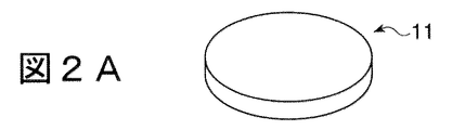
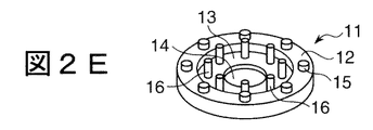
- FIGS. 2A to 2F are process diagrams showing a method for manufacturing a filter for filtration according to the first embodiment.
- the filter 10 for filtration is manufactured as follows.
- a substrate 11 as a constituent material is prepared (FIG. 2A).
- the substrate 11 is, for example, a silicon substrate having a smooth surface. In the case of a circle, the substrate 11 has a disk shape with a diameter of 5 to 450 mm. In the case of a rectangle, the substrate 11 has a rectangular plate shape with a side of about 5 mm to 450 mm. Is, for example, 0.8 to 1.2 mm.
- the surface roughness (Ra) of the silicon substrate is 1/10 or less of a gap between thick plate portions to be described later of the substrate 11, for example, about 0.1 nm.
- a glass plate, a ceramic plate, and a metal plate are preferably used.
- the substrate 11 may be a rectangular plate or a hexagonal plate in addition to a circular plate. In this case, the filter 10 for filtration becomes a square pillar body or a hexagonal pillar body.
- a counterbore is formed at the center of the surface of the substrate 11 (FIG. 2B).
- a semiconductor manufacturing technique is preferably used, that is, the substrate 11 is accommodated and supported in, for example, a processing chamber of a plasma etching apparatus, and a portion other than the spot facing is covered with a mask material.
- the surface of the substrate 11 has a counterbore 18 having a width of 0.1 to 10 mm and a depth of 0.1 to 0.6 mm on the surface of the substrate 11.
- the bank of the outer peripheral portion is formed by leaving the portion covered with the mask material without being etched.
- a thick plate portion 12 constituted by a superior outer peripheral portion and a thin plate portion 13 surrounded by the thick plate portion 12 are formed on the substrate 11 (see FIG. 3 described later).
- a through hole 14 penetrating the substrate 11 from the front and back is formed at the center of the thin plate portion 13 forming the bottom portion of the spot facing portion 18 (FIG. 2C).
- the plasma etching technique is also preferably used for the through hole 14.
- the through-hole 14 communicates with a through-hole of another substrate to form a flow path 17 for the liquid to be processed or the filtrate of the filter 10 for filtration.
- the diameter of the through hole 14 is, for example, 1 to 100 mm.
- a stopper as a first spacing member that defines the spacing between the substrates 11 is formed on the thick plate portion 12 (FIG. 2D).
- a mask material made of polyimide, for example, having a diameter and a number of openings corresponding to the cylindrical stopper 15 is placed on the thick plate portion 12 of the substrate 11, and platinum, for example, is formed by chemical vapor deposition (CVD).
- CVD chemical vapor deposition
- Pt is deposited to form cylindrical stoppers 15 having a diameter of 0.1 to 10 mm and a height of 10 to 20 nm, for example, at intervals of 1 to 100 mm.
- Adjustment of the height of the stopper 15 may be controlled by the deposition time, or may be monitored by providing a sensor for detecting the thickness, or the height may be adjusted by etching back after depositing an appropriate thickness. May be.
- eight stoppers 15 are formed at equal intervals on the thick plate portion 12 constituting the outer peripheral portion of the substrate 11.
- a resin such as polyimide, ceramics, glass, silicon, SiC, or the like is suitably applied.
- the stopper 15 is formed by a physical method.
- the shape, number and interval of the stoppers 15 are not particularly limited. Although the case where the stopper 15 is cylindrical has been described in the present embodiment, it may be a prism or any other shape. The shape, number and interval of the stoppers 15 can be changed by exchanging the mask material.
- a large number of the substrates 11 on which the stoppers 15 are formed are stacked through the second spacing member.
- eight pillars 16 as second spacing members are arranged at equal intervals of 1 to 100 mm, for example, along the outer peripheral direction of the thin plate portion 13 of the substrate 11 (FIG. 2E).
- the pillar 16 is separately formed by a known method.
- the number and interval of the pillars 16 are not particularly limited, and may be any number and interval that can accurately define the interval between adjacent substrates 11 when heated by thermal expansion.
- the pillar 16 is a cylindrical body made of a material having a thermal expansion coefficient larger than that of the stopper 15, for example, aluminum.
- the pillar 16 is disposed on the thin plate portion 13, its upper end surface is flush with the upper end surface of the stopper 15 at room temperature. Is adjusted to the height to form. That is, the height of the pillar 16 is obtained by adding the height of the stopper 15 to the depth of the counterbore portion 18.
- the material of the pillar 16 other than aluminum, for example, gold (Au), zinc, aluminum, silver, chromium, tin, iron, copper, lead, nickel, aluminum bronze, brass, duralumin, stainless steel, etc. are suitably applied.
- Au gold
- zinc, aluminum, silver, chromium, tin, iron, copper, lead, nickel, aluminum bronze, brass, duralumin, stainless steel, etc. are suitably applied.
- photoresist, polyester, polyethylene, polyvinyl chloride, polystyrene, and polycarbonate are also applicable. Since these have a relatively large coefficient of thermal expansion, the expansion allowance when heated is long, and accordingly, the gap between the substrates 11 during heating can be widened.
- the same material as the stopper 15 is used as the material of the pillar 16, it is possible to widen the gap between the base materials 11 during heating because of the difference in the extension allowance due to the difference in the overall length of each.
- the same material can be used for the pillar 16 and the stopper 15.
- a plurality of substrates 11 on which pillars 16 are arranged are sequentially laminated to form a filter 10 for filtration as a substrate laminate (FIG. 2F).
- an adhesive may be applied to a necessary portion such as the stopper 15 as necessary. It is preferable that the adhesive is elastic so as to allow thermal expansion of the pillar 16 so that the gap between the substrates 11 is widened when heated, and in particular, it can be expanded and contracted.
- the method of providing the spot facing portion 18, the method of forming the stopper 15, the method of forming the through-hole 14, etc. are not particularly limited, and a predetermined surface roughness is applied to the substrate having the required surface roughness. Any method may be used as long as the spot facing portion 18 can be formed, or the stopper 15 having a predetermined height can be formed at a predetermined position.
- plasma etching, CMP (chemical mechanical polishing), or the like is used.
- the stopper 15 can be formed by CVD, ALD, sputtering, plasma etching, or any combination thereof.
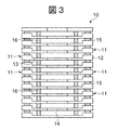
- FIG. 3 is a cross-sectional view along the longitudinal direction of the filter for filtration according to the first embodiment
- FIG. 4 is a plan view of a substrate that is a constituent member of the filter for filtration.
- the substrate 11 includes a thick plate portion 12, a plurality of stoppers 15 provided on the thick plate portion 12, and a plurality of thin plate portions 13 provided with a through hole 14 in the center. A large number of layers are stacked via the pillars 16 to form the filter 10 for filtration.
- the lowermost substrate 11 forming the bottom of the filter 10 for filtration one having no through hole 14 is applied, and as the uppermost substrate 11 forming the lid portion of the filter 10 for filtering, the counterbore 18 A substrate 11 having no is applied.
- the substrate 11 has a thick plate portion 12 that forms the periphery thereof, and a central thin plate portion 13 surrounded by the thick plate portion 12.
- a stopper 15 is provided.
- the height of the stopper 15 defines the distance between the substrates 11 and defines the opening width at the time of filtration at normal temperature, that is, normal temperature processing.
- the outer peripheral surface of the filter for filtration 10 becomes a filtration surface, and contaminants such as bacteria are captured by the gaps between the substrates 11 on the outer peripheral surface, and are surrounded by the adjacent substrates 11 and the adjacent stoppers 15.
- the space portion becomes a flow path of the liquid to be processed.
- the stopper 15 is made of a material that is relatively stable against heat change and has a small coefficient of thermal expansion
- the pillar 16 is made of a material that is relatively sensitive to heat change and has a large coefficient of thermal expansion. It is configured.
- the thermal expansion coefficient of platinum suitably used as the material of the stopper 15 is 9 ( ⁇ 10 ⁇ 6 / ° C.)
- the thermal expansion coefficient of metallic aluminum suitably used as the material of the pillar 16 is 23 ( ⁇ 10 ⁇ 6 / ° C.).
- the upper end surface of the stopper 15 and the upper end surface of the pillar 16 at the normal temperature are on the same plane, and the interval between the base materials 11 at the normal temperature is stably defined by the stopper 15 and the pillar 16. In this specification, normal temperature is 25 ° C. ⁇ 15 ° C., and is 25 ° C. unless otherwise specified.
- the filtration process using the filter 10 for filtration is normally performed at normal temperature.
- the liquid A to be treated containing contaminants such as various bacteria flows from the gaps between the substrates 11 on the outer peripheral surface of the cylindrical filter 10 and flows toward the central axis.
- the flow path 17 formed by communicating 14 is circulated and discharged as an upward flow, for example.
- the height of the stopper 15, that is, the opening width is 10 nm, germs and the like having an outer diameter larger than 10 nm contained in the liquid to be processed A are captured in the gaps between the substrates 11.
- the filtration process at normal temperature is continued for a predetermined time, and the filtration filter 10 is regenerated when solid matter such as bacteria accumulates in the gaps between the substrates 11 on the outer peripheral surface of the cylindrical body, which is the filtration surface, and the filtration speed becomes slow. .
- the regeneration of the filter 10 is performed as follows.
- the supply of the liquid A to be treated is stopped, and 75 ° C. backwash water, for example, is circulated in the direction opposite to that during the filtration treatment from the flow path 17 along the central axis of the substrate laminate.
- backwash water for example, a part of the treatment liquid recovered as a filtrate is used.
- the stopper 15 disposed between the thick plate portions 12 of the substrate 11 does not expand so much because the coefficient of thermal expansion is small.
- the pillars 16 disposed between the thin plate portions 13 have a large coefficient of thermal expansion and thus thermally expand.
- the extension allowance is large, and thereby the space
- the thickness of the thick plate portion 12 of the substrate 11 is 1 mm
- the thickness of the thin plate portion 13 is 0.4 mm
- the height of the stopper 15 made of platinum at normal temperature that is, the gap between the thick plate portions 12 is 10 nm
- the metal at normal temperature When the height of the pillar 16 made of aluminum is 0.6 mm (more precisely, 0.6 mm + 10 nm) and the temperature of the backwash water is 75 ° C., the extension allowance of the pillar 16 on the substrate 11 at the time of backwashing is obtained as follows. become.
- the height of the pillar 16 when backwashed with backwash water at 75 ° C. is 690 nm longer than the height at normal temperature, and thereby the space between the thick plate portions 12 of the adjacent substrates 11 is expanded. Compared to 10 nm at room temperature, it spreads greatly. Therefore, contaminants such as germs trapped in the gaps between the thick plate portions 12 of the substrate 11 are easily detached.
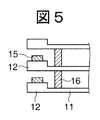
- FIG. 5 is a partially enlarged view of the filter 10 for filtration in which the interval between the thick plate portions 12 of the substrate 11 is widened.
- the pillars 16 are thermally expanded, whereby the distance between the thick plate portions 12 of the substrate 11 is widened. Therefore, regeneration by backwashing becomes easy.
- the cleaning water can be washed by flowing in the forward direction instead of the reverse direction. Also in this case, the miscellaneous bacteria trapped in the gap are released from the widened gap and washed with washing water.
- it is preferable to flow in the reverse direction as described above when washing water can flow in the reverse direction, but if it is difficult to flow in the reverse direction due to the convenience of the system, As described above, the washing water may flow in the forward direction.
- the gap between the thick plate portions 12 of the substrate 11 is mainly set to 10 nm, for example, by the stopper 15 during the filtration treatment at room temperature, and the substrate 16 is heated by the pillar 16 using heated water during the regeneration. Since the distance between the thick plate portions 12 can be increased to about 700 nm, a stable opening can be obtained during the filtration treatment, and during the regeneration, the trapped material can be separated and easily regenerated by widening the opening.
- the outer peripheral surface of the cylindrical body becomes a filtration surface, and the filtration area can be increased, so that the processing capability is improved.
- semiconductor manufacturing technology can be applied as a processing method for the substrate 11 and the like, it is possible to manufacture a precise filter for filtration using a constituent material with high dimensional accuracy.
- the length of the pillar 16 is obtained by adding the height of the stopper 15 to the depth of the counterbore 18, thereby defining the distance between the substrates 11 at the normal temperature by the stopper 15 and the pillar 16.
- the length of the pillar 16 is slightly shorter than that of the depth of the counterbore 18 plus the height of the stopper 15, whereby the distance between the substrates 11 at room temperature is reduced.
- the distance between the substrates 11 during heating may be defined by the thermally expanded pillars 16.
- the number of stacked base materials 11 is not particularly limited, and is adjusted according to the required filtration processing capacity. For example, several cylindrical filters stacked in units of 100 sheets are used. Or dozens can be connected in series. As a result, a filter for filtration having a high throughput can be realized.
- the filter for filtration which concerns on this Embodiment is not specifically limited, It applies suitably as a filter for the purification of tap water in a water purification plant.
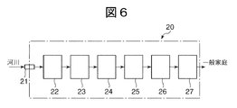
- FIG. 6 is a block diagram showing a configuration of a water purification plant to which the filter for filtration according to the present embodiment is applied.
- the water purification plant 20 includes, for example, a water intake 21 for taking in river water from a river, a coagulation sedimentation basin 22 for removing solids contained in the fetched river water, and a downstream of the coagulation sedimentation basin 22. It is mainly composed of a rapid filtration basin 23, an ozone contact basin 24, an activated carbon adsorption basin 25, a chlorine-mixing basin 26 and a water purification basin 27 which are sequentially provided.
- the river water taken in from the water intake 21 first flows into a sedimentation basin (not shown) called a sedimentation basin, and solids such as sand are settled and separated, and then sent to the coagulation sedimentation basin 22.
- a flocculant is added to the water flowing into the coagulation sedimentation basin 22, and solids such as plankton are coagulated to settle and separate, and only the supernatant water is sent to the rapid filtration basin 23 in the downstream.
- the water that has flowed into the rapid filtration basin 23 passes through a filtration layer filled with fine sand, for example, and is removed from the finer solid matter, and then sent to the downstream ozone contact basin 24.
- the water that has flowed into the ozone contact basin 24 comes into contact with ozone and decomposes substances that cause turbidity and odor, and then flows into the activated carbon adsorption pond 25 that is downstream.
- the water flowing into the activated carbon adsorption pond 25 is adsorbed and removed by the minute substances that could not be sufficiently removed by ozone, and then flows into the downstream chlorine mixing pond 26 where a predetermined amount of chlorine is mixed. Disinfected.
- the water sterilized with chlorine is stored in the water purification pond 27 as drinking tap water, and is supplied to ordinary households as needed.
- the filter 10 for filtration is applied as an alternative facility for the ozone contact pond 24 and the activated carbon adsorption pond 25, for example.
- the water flowing out from the rapid filtration pond 23 flows into the filtration filter 10 as the liquid A to be treated, and separates and purifies contaminants such as bacteria of 10 nm or more that could not be removed by the rapid filtration pond 23. Is done.
- the liquid A to be treated at room temperature flows into the filtration filter 10 from the gap between the substrates 11 of the filtration surface formed on the outer circumferential surface of the filtration filter 10 and flows toward the central axis. Through the flow path 17 formed along the axis, it is recovered as the processing liquid B (see FIG. 1) and flows into the downstream chlorine-mixing basin 26.
- the filtrate of the filtration filter 10 that has flowed into the chlorine-mixing pond 26 is stored in the water purification pond 27 after a predetermined amount of chlorine is added and sterilized.
- contaminants such as germs are captured and separated on the filtration surface, which is the outer peripheral surface of the filtration filter 10.
- the distance between the thick plate portions 12 of the substrate 11 defined by the stopper 15 is, for example, 10 nm, and contaminants larger than that, for example, germs such as influenza virus, are reliably collected on the filtration surface.
- the filtering filter 10 is regenerated. That is, in the filtration filter 10 in which clogging has occurred, the supply of the outlet liquid of the rapid filtration pond 23 as the liquid to be treated A is stopped, and for example, backwash water is used from the direction opposite to the flow direction of the liquid A to be treated. Circulate.
- backwash water for example, water flowing into the chlorine-mixing pond 26 that is the filtrate of the filter 10 for filtration is used. At this time, the temperature of the backwash water is heated to, for example, 70 to 80 ° C., which is higher than normal temperature.
- the filtration filter 10 in which the high-temperature backwash water is circulated widens the gaps between the thick plate portions 12 of the substrate 11 constituting the filtration surface, and thereby contaminants such as various bacteria trapped in the gaps. Is removed, and the filter 10 for filtration is regenerated.
- the backwash water containing various germs and the like separated from the filtration surface is returned to the upstream of the coagulation sedimentation basin 22 or processed separately.
- the opening in the filtration surface of the filter 10 for filtration can be changed greatly between the room temperature at which the filtration process is performed and the heating at which the regeneration process is performed.
- the contaminants captured during regeneration can be easily separated and easily regenerated.
- the filter 10 for filtration is composed of a substrate laminate, the mechanical strength is high and pressure filtration can be performed. Therefore, the amount of processing liquid increases and the processing time can be shortened.
- the filtration filter 10 is applied as a water purification device in a water purification plant, but the filtration filter 10 is applied as a medical device, for example, a blood or protein component separation or an artificial dialysis filtration device. You can also. Further, the present invention can be applied as a cleaning water purifier for wet cleaning in a semiconductor manufacturing factory.
- a substance having an inverse piezoelectric effect for example, quartz (SiO 2 ), zinc oxide (ZnO), Rochelle salt (potassium tartrate - sodium) (KNaC 4 H 4 O 6 ), lead zirconate titanate (PZT: Pb (Zr, Ti ) O 3), lithium niobate (LiNbO 3), lithium tantalate (LiTaO 3), Lithium tetraborate (Li 2 B 4 O 7 ), langasite (La 3 Ga 5 SiO 14 ), aluminum nitride (AlN), tourmaline (tourmaline), polyvinylidene fluoride (PVDF), gallium phosphate (GaPO 4 ), Gallium arsenide (GaAs) or the like can be used. Since these substances expand by applying a voltage, they are suitable as pillar materials.
- the filter 10 for filtration according to the present embodiment is decomposed when the lifetime of the filtration device is exhausted, and if the stopper 15 or the like attached to the substrate 11 is removed, almost 100% of the base material is reused. Can do.
- the filtration filter 10 as a whole substrate laminate can be integrated by fastening with a fastening member.
- FIG. 7 is a perspective view showing a filter for filtration fixed by a fastening member.
- the cylindrical filter 10 for filtration is integrated by being clamped in the vertical direction in FIG. 7 by two clamping members 30 arranged opposite to each other.
- the fastening member 30 is mainly composed of a bowl-shaped non-elastic portion 30a constituting both ends and an elastic portion 30b connecting the two non-elastic portions 30a.
- the non-elastic part 30a is made of metal, for example, stainless steel
- the elastic part 30b is made of, for example, a spring member whose main component is stainless steel.
- the tightening force of the tightening member 30 is adjusted to allow thermal expansion of the pillars 16 disposed between the substrates 11 by the elasticity of the elastic portion 30b.
- the material used for the elastic portion 30b may be an organic material having elasticity such as rubber as a consumable by adopting a structure that can be easily replaced.
- the flow direction of the liquid A to be treated is described as flowing out from the filtration filter 10 as an upward flow from the outer peripheral surface of the cylindrical filtration filter 10 through the flow path 17 along the central axis.
- the flow direction of the water in the filtration filter 10 according to the present embodiment is not limited to this, and the flow path 17 formed along the central axis of the cylindrical filtration filter 10 is treated.
- the liquid A may be used as an introduction path, and may flow through the introduction path and through the gaps between the substrates 11 and out of the outer peripheral surface.
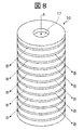
- FIG. 8 is an explanatory diagram showing another use situation of the filter for filtration.
- the liquid A to be processed flows into the filtration filter 10 from above, flows as a downward flow through the flow path 17 along the cylindrical central axis, and then flows through the gaps between the substrates 11. Then, it flows out from the filter 10 for filtration as the processing liquid B through the opening on the outer peripheral surface.
- the filtration surface in the filter for filtration 10 becomes a surface connecting the inner side surfaces of the thick plate portion 12 of each substrate 11, and the contaminant contained in the liquid A to be processed connects the inner side surface of the thick plate portion 12. Captured at the filtration surface.
- the distance between the substrates 11 can be changed depending on the height, and the apparatus can be used as a separation device for fine solids contained in the liquid to be processed.
- the pressure applied to the filter 10 for filtration acts in the direction of widening the interval between the substrates 11. Therefore, in the case of performing high-pressure filtration, it is preferable that the flow direction of the liquid to be treated is the direction shown in FIG.
- the through hole 14 may be an aggregate of a plurality of small holes.
- FIG. 9 is a diagram showing a modification of the substrate 11 in the present embodiment.
- a plurality of small holes 14 a are provided in the central portion of the thin plate portion 13 that forms the bottom portion of the counterbore portion 18 of the substrate 11.
- the aggregate of the through holes 14 a forms a flow path 17 along the central axis of the filter 10 for filtration in which the substrates 11 are stacked. In this case, the structure becomes complicated and the manufacturing cost increases, but the strength as the substrate 11 is improved.
- This filtration filter has a basic configuration including the point that the interval between the thick plate portions of each substrate in the substrate laminate in which a large number of substrates having thick plate portions and thin plate portions are laminated defines the opening width in the filtration surface. This is the same as the filter for filtration according to the first embodiment.
- the filter for filtration according to the second embodiment is different from the filter for filtration according to the first embodiment in that the length of the thick plate portion of the substrate is longer than the length of the outer peripheral portion of the substrate and the filtration is wide. It is the point which secured the area.
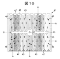
- FIG. 10 is a plan view of a substrate applied to the second embodiment of the present invention
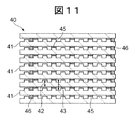
- FIG. 11 is a cross-sectional view showing a main part of a filter for filtration in which a large number of substrates of FIG. 10 are stacked.
- the substrate 41 has a rectangular plate shape, and includes a thick plate portion 42 and a thin plate portion 43.
- the thick plate portions 42 are arranged in two rows of zigzag patterns that are repeatedly folded back in two regions of the substrate 41 depicted at the top and bottom of FIG. 10, and two rows of zigzag thick plate portions 42.
- a thin plate portion 43 is formed so as to be surrounded by the loop-shaped thick plate portion 42, and a through hole 44 penetrating the substrate 41 in the thickness direction is provided at the center of the substrate 41 in the thin plate portion 43. .
- a large number of rectangular columnar stoppers 45 as first spacing members are provided at intervals.
- the shape of the stopper 45 is not limited to a square column shape, and may be a columnar shape or other column shapes.
- a large number of pillars 46 as second spacing members are provided at intervals.
- the shape of the pillar 46 is, for example, a cylindrical shape, but is not limited thereto.
- a large number of substrates 41 are stacked via a plurality of stoppers 45 and pillars 46 to form a square columnar filter 40 for filtration.
- a circular plate-shaped silicon wafer is prepared as a raw material substrate for manufacturing a substrate.
- the silicon wafer has a smooth surface, and its diameter is, for example, 50 to 450 mm, and its thickness is, for example, 0.1 to 3 mm.
- the surface roughness (Ra) of the silicon wafer is preferably 1/10 or less of the gap between the thick plate portions 42 of the substrate 41 in the filter 40 for filtration, for example, about 0.1 nm.
- a glass plate, a ceramic plate, and a metal plate can be applied in addition to a silicon wafer.
- a zigzag thick plate portion 42 is formed on the surface of the silicon wafer.
- a semiconductor manufacturing technique is preferably used for forming the thick plate portion 42. That is, a silicon wafer is accommodated and supported in a processing chamber of a plasma etching apparatus, for example, and a mask material corresponding to the zigzag thick plate portion 42 is placed thereon, and then a plasma etching process is performed. A zigzag thick plate portion 42 that remains without being etched and a thin plate portion 43 surrounded by the thick plate portion 42 are formed. At this time, from one circular plate-shaped silicon wafer, for example, four substrates arranged in two rows and two rows are formed on the surface of the silicon wafer, and then cut out to prepare the substrate 41.
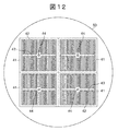
- FIG. 12 is a plan view showing four substrates 41 formed on the silicon substrate 50 when the four substrates 41 are cut out from one silicon wafer 50.
- FIG. 12 on a circular silicon wafer 50, four substrates 41 having a thick plate portion 42 formed in a zigzag shape and a thin plate portion 43 surrounded by the thick plate portion 42 are formed in two rows and two rows. .
- the substrate 41 formed in this way is cut out by a known method.
- the stopper and the pillar are not shown.
- the thickness of the thick plate portion 42 is, for example, 0.1 to 3 mm
- the width is, for example, 0.45 to 10 mm
- the thickness of the thin plate portion 43 is, for example, 0.1 ⁇ 3mm.
- the total length of the thick plate portion 42 in one substrate 41 is, for example, 1600 to 16000 mm, which is about 10 times the length when the thick plate portion is disposed along the outer peripheral portion of the substrate 41.
- the diameter of the through hole 44 is, for example, 10 mm, and in a filtration filter in which a large number of substrates are stacked, a central flow path is formed that communicates with the through holes 44 of the substrate 41 adjacent in the stacking direction and through which the liquid to be treated or the filtrate flows. To do.
- a stopper 45 as a first interval holding member that defines the interval between the substrates 41 is formed in the same manner as in the first embodiment (see FIG. 10, see FIG.
- the stopper 45 is a cylindrical member made of, for example, platinum, polyimide, ceramics, glass, silicon, SiC, or the like, and is formed by, for example, a chemical vapor deposition (CVD) method.
- the length of one side of the rectangular cross section of the stopper 45 is, for example, 0.1 to 10 mm, and the height is defined to be, for example, 10 to 20 nm according to the filtration object, which is necessary to maintain the distance between adjacent substrates. For example, they are formed at equal intervals.
- a number of pillars 46 as second spacing members are provided at arbitrary locations on the thin plate portion 43 of the substrate 41 where the stoppers 45 are formed on the thick plate portion 42. For example, it arrange
- the pillar 46 is separately formed by a known method.
- the number and interval of the pillars are not particularly limited, and may be any number and interval that can accurately define the interval between the adjacent substrates 41 at a predetermined value during the thermally expanded heating.
- the pillar 46 is made of a material having a coefficient of thermal expansion larger than that of the stopper 45, for example, aluminum.
- the upper end surface forms, for example, the same plane as the upper end surface of the stopper 45 at room temperature. It is adjusted to the height to do.
- gold (Au) gold
- zinc, aluminum, silver, chromium, tin, iron, copper, lead, nickel, aluminum bronze, brass, Duralumin, stainless steel and the like are preferably applied.
- photoresist, polyester, polyethylene, polyvinyl chloride, polystyrene, and polycarbonate are also applicable. Since these have a relatively large thermal expansion coefficient, the gap between the substrates 41 at the time of heating can be made wider than the interval at the normal temperature.
- a plurality of substrates 41 provided with stoppers 45 and pillars 46 are sequentially laminated to form a filter 40 for filtration as a substrate laminate (see FIG. 11).
- an adhesive may be applied to a necessary portion such as the stopper 45 as necessary.
- An adhesive having elasticity is applied to allow thermal expansion of the pillar 46.
- the liquid A to be treated is a gap between the substrates 41 of the square columnar filter 40, that is, between the thick plate portions 42 arranged in a zigzag shape. It flows into the filter 40 for filtration through the gap, flows into the thin plate portion 43 as a filtrate from which contaminants have been removed on the filtration surface formed by the thick plate portion 42, and then flows toward the center of the substrate 41, A central flow path communicating with a through hole 44 provided in the central portion of the substrate 41 flows, for example, as an upward flow and is collected.
- the thick plate portion 42 in the substrate 41 is arranged in a zigzag shape and the length thereof is longer than the length of the outer peripheral portion of the substrate 41, the filtration area can be remarkably increased. This improves the filtration efficiency of the liquid to be treated.
- the length of the pillar 46 is made longer than the length of the stopper 45, and a material having a thermal expansion coefficient larger than that of the constituent material of the stopper 45 is applied as the constituent material of the pillar 46.
- the interval between the substrates 41 is stably defined by the stopper 45 at room temperature, and at the time of reproduction, the pillars 46 are thermally expanded by, for example, heated water to widen the interval between the substrates 41. Therefore, a stable opening can be obtained at the time of filtration, and it can be easily regenerated when clogged.
- the flowing direction of the heated water is usually the reverse direction during the filtration process, but may be the forward direction.
- the area of the thin plate portion 43 in the substrate 41 is preferably 30% or less of the area of the substrate 41. This makes it easy to ensure the strength of the substrate.
- the diameter of the through hole 44 is preferably, for example, 1 to 10 mm or less in order to ensure the residence time of the liquid to be processed in the filter 40 for filtration.
- the through hole 44 is formed by, for example, dry etching or machining.
- four substrates 41 formed in two rows and two rows are cut out as one unit on the surface of the silicon wafer 50, and a large number of these substrates are stacked to form a substrate stack.
- FIG. 13 is a plan view showing a substrate assembly having four substrates 41 as one unit.
- FIG. 13 shows a substrate assembly composed of four substrates cut out from the silicon wafer 50.
- a filter for filtration can also be formed by laminating a large number of such substrate assemblies in the same manner as in the second embodiment. Further, it is possible to form a filter for filtration by laminating a large number of substrate aggregates formed on the silicon wafer 50 together with the silicon wafer 50 without cutting out the substrate aggregate. In such a filter for filtration, the same effect as in the second embodiment can be obtained.
- the stopper and the pillar are not shown.
- the shape of the thick plate portion 42 of the substrate 41 is a zigzag shape, but the shape of the thick plate portion 42 is not limited to this, and for example, surrounds the spiral thin plate portion 43. It is possible to have a double spiral shape.
- This filter for filtration has the basic configuration including the point that the distance between the thick plate portions of each substrate in the substrate laminate in which a large number of substrates having thick plate portions and thin plate portions are laminated defines the opening width in the filtration surface. This is the same as in the first and second embodiments.
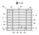
- FIG. 14 is a cross-sectional view showing the main part of the filter for filtration according to the third embodiment of the present invention.
- a large number of substrates 61 having thick plate portions 62 and thin plate portions 63 are laminated to form a filter 60 for filtration.
- the filter for filtration according to the third embodiment is characterized by its manufacturing method.
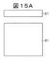
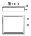
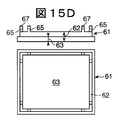
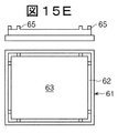
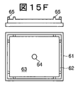
- 15A to 15F are process diagrams showing a method for manufacturing a filter for filtration according to the third embodiment of the present invention.
- the filter 60 for filtration is manufactured as follows.
- 15A to 15F show a set of a side view and a plan view of a substrate in each manufacturing process, with the upper view being a side view and the lower view being a plan view.
- a substrate 61 as a constituent material is prepared (FIG. 15A).
- the substrate 61 is, for example, a rectangular flat silicon substrate having smooth surfaces on the front and back sides, and one side thereof is, for example, 5 mm to 450 mm.
- the thickness is, for example, 0.8 to 1.2 mm.
- the surface roughness (Ra) of the silicon substrate is 1/10 or less of the gap between the thick plate portions 62 when the substrates 61 are laminated, for example, about 0.1 nm.
- a mask material 67 having a line width of, for example, 0.8 mm to 1.2 mm is applied all around the outer periphery of the substrate 61 slightly inside, for example, 1 to 10 mm (FIG. 15B).
- the mask material 67 for example, super heat-resistant and cold-resistant polyimide (trade name: Kapton), a photoresist used in manufacturing a semiconductor device, or the like is preferably used.
- the substrate 61 coated with the mask material 67 is accommodated in the chamber of the substrate processing apparatus, the pressure in the chamber is set to 1 to 1000 mTorr (0.133 to 133 Pa), for example, and etching gases such as HBr, ammonia ( Using a mixed gas of NH 3 ) and oxygen (O 2 ), etching is performed in the thickness direction of the substrate 61 to a depth of, for example, about 300 ⁇ m, and thereby a thin plate portion surrounded by a convex portion covered with a mask material 67 63 is formed (FIG. 15C).
- etching gases such as HBr, ammonia ( Using a mixed gas of NH 3 ) and oxygen (O 2 )
- a part of the mask material 67 that is, a portion other than the portion serving as the stopper 65 as the interval holding portion is peeled off, and a plasma etching process is performed under the same conditions as described above, whereby the thick plate portion 62 and the thickness are increased.
- a stopper 65 protruding from the plate portion 62 is formed (FIG. 15D).
- the etching conditions are adjusted to adjust the height of the stopper 65 to a height corresponding to the size of the target component to be removed by the filter 60 for filtration, for example, 1 to 100,000 nm.
- the number and interval of the stoppers 65 are not particularly limited as long as the interval between the substrates 61 can be stably maintained at a predetermined interval.
- the mask material 67 is peeled off from the stopper 65 of the substrate 61 on which the stopper 65 is formed (FIG. 15E), and a through hole 64 is formed in the center of the thin plate portion 63 to serve as a constituent member of the filter 60 for filtration.
- the substrate 61 is completed (FIG. 15F).
- a large number of pillars 66 as interval holding members are arranged, for example, at equal intervals, at an arbitrary position of the thin plate portion 63 of the obtained substrate 61.
- a large number of, for example, several tens to 100 substrates 61 are stacked through the pillar 66 and the stopper 65 to form the filter 60 for filtration.
- the formation of the thick plate portion 62 and the thin plate portion 63 and the subsequent formation of the stopper 65 can be performed by the plasma etching process, so that the manufacturing process can be simplified and the productivity is improved. improves.
- the stopper 66 that is, a material having a larger thermal expansion coefficient than the constituent material of the substrate 61 is applied as the constituent material of the pillar 66, and
- the height higher than the stopper 65 specifically, by making the difference between the thickness of the thick plate portion 62 and the thin plate portion 63 and the sum of the height of the stopper 65 or slightly longer than that,
- the interval between the substrates 61 is stably defined by the stopper 65 at normal temperature.
- the pillar 66 can be thermally expanded at the time of regeneration in which heated water is circulated to widen the interval between the substrates 61. When it is obtained and clogged, it can be easily regenerated and used repeatedly.
- the liquid A to be treated flows into the main body of the filter 60 for filtration from the gap between the substrates 61 on the outer peripheral surface of the filter 60 for filtration (see FIG. 14).
- the filtrate is obtained by filtering the target component according to the interval, and flows, for example, as an upward flow through the central flow path communicating with the through hole 64 (see FIG. 15F) formed in the central portion, and flows out from the filter 60 for filtration.
- the liquid A to be treated can be introduced from the central flow path, for example, as a downward flow, and then flow between the substrates 61 toward the outer periphery of the filter 60 for filtration.
- the shape of the substrate 61 is a rectangular plate, but the shape of the substrate 61 is not particularly limited, and in addition to the rectangular plate, a circular plate or an elliptic plate Further, it may be a plate-like body having another shape, and may be applied when forming the filter according to the first embodiment or the second embodiment.
- a super heat-resistant and cold-resistant polyimide (trade name: Kapton) or a photoresist is used as a masking material, but other than this, for example, metal, carbon, quartz, or the like can also be used.
- the filter 60 for filtration can be integrated by using a fastening member having elasticity, an adhesive having elasticity, or the like. The form as the filter 60 for use is stabilized.
- a substance having an inverse piezoelectric effect such as quartz (SiO 2), is used as in the first embodiment. 2), zinc oxide (ZnO), Rochelle salt (potassium tartrate - sodium) (KNaC 4 H 4 O 6 ), lead zirconate titanate (PZT: Pb (Zr, Ti ) O 3), tourmaline, Polyvinylidene fluoride (PVDF), gallium phosphate (GaPO 4 ), gallium arsenide (GaAs), or the like can be used.
- ZnO zinc oxide
- Rochelle salt potassium tartrate - sodium
- PZT lead zirconate titanate
- PVDF Polyvinylidene fluoride
- GaPO 4 gallium phosphate
- GaAs gallium arsenide
Landscapes
- Chemical & Material Sciences (AREA)
- Chemical Kinetics & Catalysis (AREA)
- Engineering & Computer Science (AREA)
- Water Supply & Treatment (AREA)
- Life Sciences & Earth Sciences (AREA)
- Geology (AREA)
- Nanotechnology (AREA)
- Ceramic Engineering (AREA)
- Inorganic Chemistry (AREA)
- Filtering Materials (AREA)
- Separation Using Semi-Permeable Membranes (AREA)
- Filtration Of Liquid (AREA)
Abstract
Description
600(μm)×23(×10−6)×(75−25)×1000=690(nm)となる。
11、41、61 基板
12、42、62 厚板部
13、43、63 薄板部
14、14a、44、64 貫通孔
15、45、65 ストッパー
16、46、66 ピラー
17 流路
18 座ぐり部
67 マスク材
Claims (21)
- 表裏に貫通する貫通孔を有する基板を多数積層した基板積層体と、
該基板積層体における基板相互の間隔を規定する第1の間隔保持部材及び該第1の間隔保持部材よりも熱膨張係数が大きい第2の間隔保持部材と、を有し、
前記基板相互間の常温時の間隔を少なくとも前記第1の間隔保持部材で規定すると共に加熱時の間隔を熱膨張した前記第2の間隔保持材で規定し、前記基板相互間の隙間で被処理液に含まれる目的成分を捕捉する濾過面を形成することを特徴とする濾過用フィルター。 - 前記基板は、厚板部と薄板部を備え、前記第1の間隔保持部材は、前記厚板部相互間に間隔を置いて複数配置され、前記第2の間隔保持部材は、前記薄板部相互間に間隔を置いて複数配置され、前記第2の間隔保持部材の長さを前記第1の間隔保持部材の長さよりも長くしたことを特徴とする請求項1記載の濾過用フィルター。
- 前記厚板部は前記基板の外周部を形成し、前記薄板部は前記厚板部で囲まれた前記基板の中央部を形成し、前記薄板部の中心部に前記貫通孔が設けられていることを特徴とする請求項2記載の濾過用フィルター。
- 前記厚板部は、前記基板表面に当該厚板部の全長が前記基板の外周部の長さよりも長くなるように、且つ環状に配設され、前記薄板部は、前記厚板部で囲まれ、且つ前記基板の中心部を有し、該基板の中心部に前記貫通孔が設けられていることを特徴とする請求項2記載の濾過用フィルター。
- 前記厚板部は、2列のジグザク状線部のそれぞれの端部が連結されたループ状として前記基板表面上に配設されていることを特徴とする請求項4記載の濾過用フィルター。
- 前記貫通孔は、前記基板積層体における他の基板の貫通孔と連通して被処理液又は濾液の流路を形成することを特徴とする請求項1記載の濾過用フィルター。
- 前記基板の前記厚板部の表面粗度(Ra)は、前記厚板部互間の隙間の1/10以下であることを特徴とする請求項1記載の濾過用フィルター。
- 前記基板は、シリコン、ガラス、セラミック、金属、炭化珪素をはじめとするシリコン化合物、ポリイミドをはじめとする樹脂、及びカーボンのいずれかからなることを特徴とする請求項1記載の濾過用フィルター。
- 前記基板積層体は、前記第2の間隔保持部材の熱膨張を許容する締め付け部材によって一体化されていることを特徴とする請求項1記載の濾過用フィルター。
- 基板の中央部に座ぐり部を形成して前記基板の周囲を構成する厚板部と、該厚板部で囲まれた薄板部を形成する座ぐりステップと、
前記薄板部の中心部に基板の表裏に貫通する貫通孔を形成する貫通孔形成ステップと、
前記厚板部上に所定高さの第1の間隔保持部材を所定間隔で複数形成する第1の間隔保持部材形成ステップと、
前記基板の前記薄板部に前記第1の間隔保持部材よりも熱膨張係数が大きく、且つ長い複数の第2の間隔保持部材を所定間隔で複数形成する第2の間隔保持部材形成ステップと、
少なくとも前記第1の間隔保持部材を介して前記基板を多数積層する積層ステップと、
を有することを特徴とする濾過用フィルターの製造方法。 - 前記座ぐりステップは、プラズマを用いたプラズマエッチングによって前記座ぐり部を形成することを特徴とする請求項10記載の濾過用フィルターの製造方法。
- 前記座ぐりステップは、化学機械研磨(CMP)法によって前記座ぐり部を形成することを特徴とする請求項10記載の濾過用フィルターの製造方法。
- 前記第1の間隔保持部材形成ステップは、マスク材を用いた成膜法によって、前記厚板部上に第1の間隔保持部材を形成することを特徴とする請求項10記載の濾過用フィルターの製造方法。
- 前記第1の間隔保持部材形成ステップは、マスク材を用いた塗布法によって、前記厚板部上にフォトレジストからなる第1の間隔保持部材を形成するステップであることを特徴とする請求項10記載の濾過用フィルターの製造方法。
- 前記積層ステップで積層した基板積層体を、前記第2の間隔保持部材の熱膨張を許容する締め付け部材によって一体化する一体化ステップを有することを特徴とする請求項10記載の濾過用フィルターの製造方法。
- 前記基板の前記厚板部の表面粗度(Ra)は、前記厚板部相互間の隙間の1/10以下であることを特徴とする請求項10記載の濾過用フィルターの製造方法。
- 前記基板として、シリコン板、ガラス板、セラミック板、金属板、炭化珪素をはじめとするシリコン化合物板、ポリイミドをはじめとする樹脂板、及びカーボン板のいずれかを使用することを特徴とする請求項10記載の濾過用フィルターの製造方法。
- 基板表面の外周に沿って環状のマスキング材を形成するマスキングステップと、
前記環状のマスキング材が形成された基板をエッチングして前記環状のマスキング材に対応する凸部に囲まれた薄板部を形成する第1のエッチングステップと、
前記第1のエッチングステップ終了後、前記凸部上の前記マスキング材の一部を剥離させる第1のマスキング材剥離ステップと、
前記第1のマスキング材剥離ステップ後の基板をエッチングして前記第1のマスキング材剥離ステップ後に残存するマスキング材が塗布された部分以外の前記凸部で厚板部を形成すると共に、前記残存するマスキング材が塗布された部分の前記凸部で前記厚板部から突出する間隔保持部を形成する第2のエッチングステップと、
前記厚板部で囲まれた前記薄板部の中心部に当該基板を表裏に貫通する貫通孔を形成する貫通孔形成ステップと、
前記貫通孔が形成された基板の前記薄板部に前記間隔保持部よりも熱膨張係数が大きく、且つ高さが高い複数の間隔保持部材を所定間隔で複数形成する間隔保持部材形成ステップと、
前記間隔保持部から前記マスキング材を剥離する第2のマスキング材剥離ステップと、
少なくとも前記間隔保持部を介して前記基板を多数積層する積層ステップと、
を有することを特徴とする濾過用フィルターの製造方法。 - 前記積層ステップで積層した基板積層体を、前記間隔保持部材の熱膨張を許容する締め付け部材によって一体化する一体化ステップを有することを特徴とする請求項18記載の濾過用フィルターの製造方法。
- 前記基板の前記厚板部の表面粗度(Ra)は、前記厚板部相互間の隙間の1/10以下であることを特徴とする請求項18記載の濾過用フィルターの製造方法。
- 前記基板として、シリコン板、ガラス板、セラミック板、金属板、炭化珪素をはじめとするシリコン化合物板、ポリイミドをはじめとする樹脂板、及びカーボン板のいずれかを使用することを特徴とする請求項18記載の濾過用フィルターの製造方法。
Priority Applications (3)
| Application Number | Priority Date | Filing Date | Title |
|---|---|---|---|
| SG2013071022A SG193574A1 (en) | 2011-03-24 | 2012-03-13 | Filtration filter and production method therefor |
| KR1020137024910A KR101476949B1 (ko) | 2011-03-24 | 2012-03-13 | 여과용 필터 및 그 제조 방법 |
| US14/006,177 US9022225B2 (en) | 2011-03-24 | 2012-03-13 | Filtration filter and production method therefor |
Applications Claiming Priority (4)
| Application Number | Priority Date | Filing Date | Title |
|---|---|---|---|
| JP2011065997 | 2011-03-24 | ||
| JP2011-065997 | 2011-03-24 | ||
| JP2011156681A JP5547136B2 (ja) | 2011-03-24 | 2011-07-15 | 濾過用フィルター及びその製造方法 |
| JP2011-156681 | 2011-07-15 |
Publications (1)
| Publication Number | Publication Date |
|---|---|
| WO2012128235A1 true WO2012128235A1 (ja) | 2012-09-27 |
Family
ID=46879382
Family Applications (1)
| Application Number | Title | Priority Date | Filing Date |
|---|---|---|---|
| PCT/JP2012/056953 Ceased WO2012128235A1 (ja) | 2011-03-24 | 2012-03-13 | 濾過用フィルター及びその製造方法 |
Country Status (5)
| Country | Link |
|---|---|
| US (1) | US9022225B2 (ja) |
| JP (1) | JP5547136B2 (ja) |
| KR (1) | KR101476949B1 (ja) |
| SG (1) | SG193574A1 (ja) |
| WO (1) | WO2012128235A1 (ja) |
Cited By (2)
| Publication number | Priority date | Publication date | Assignee | Title |
|---|---|---|---|---|
| CN105833581A (zh) * | 2016-06-14 | 2016-08-10 | 海宁科诺过滤设备有限公司 | 一种保温层叠式板框过滤器 |
| JP2017132035A (ja) * | 2013-10-23 | 2017-08-03 | 株式会社荏原製作所 | 研磨方法および研磨装置 |
Families Citing this family (9)
| Publication number | Priority date | Publication date | Assignee | Title |
|---|---|---|---|---|
| JP6231812B2 (ja) * | 2013-08-09 | 2017-11-15 | アズビル株式会社 | 静電容量型圧力センサ |
| KR101594876B1 (ko) * | 2013-09-12 | 2016-02-17 | 한성완 | 간극형성 필터부재를 이용한 필터 조립체 |
| KR101550877B1 (ko) | 2013-10-10 | 2015-09-07 | 탱크테크 (주) | 선박 평형수 처리용 적층형 필터 엘리먼트 |
| DE102014113497B4 (de) | 2014-09-18 | 2018-06-28 | Sartorius Stedim Biotech Gmbh | Filtrationsmodul und Verfahren zur Herstellung |
| CN108535082A (zh) * | 2018-06-20 | 2018-09-14 | 南京维埃迪光电技术有限公司 | 一种多级滤膜萃取部件 |
| JP6940538B2 (ja) * | 2019-02-14 | 2021-09-29 | 日鉄ステンレス加工株式会社 | 濾板集合体保持具およびこれを備える濾過器 |
| CN110548399A (zh) * | 2019-06-01 | 2019-12-10 | 龙口市海丰环境科技工程有限公司 | 并联进水单级碟片式净水器 |
| CN110215839A (zh) * | 2019-06-01 | 2019-09-10 | 龙口市海丰环境科技工程有限公司 | 工业用并联进水双级碟片式过滤器 |
| US11684874B2 (en) * | 2020-12-29 | 2023-06-27 | Metal Industries Research & Development Centre | Tangential flow filtration module and tangential flow filtration assembly |
Citations (4)
| Publication number | Priority date | Publication date | Assignee | Title |
|---|---|---|---|---|
| JPS63107712A (ja) * | 1986-10-24 | 1988-05-12 | Kobe Steel Ltd | スクリ−ンの目詰解除装置 |
| JP2002186810A (ja) * | 2000-12-21 | 2002-07-02 | Arai Tekkosho:Kk | 固液分離用濾過エレメント |
| JP2003210916A (ja) * | 2002-01-17 | 2003-07-29 | Atom Engineering:Kk | 濾過装置の濾体、それを用いた濾過装置及び濾体用平板の製造方法 |
| JP2007130532A (ja) * | 2005-11-08 | 2007-05-31 | Toshiba Corp | 温度応答性膜、温度応答性膜モジュール、およびそれを用いた膜ろ過システム |
Family Cites Families (4)
| Publication number | Priority date | Publication date | Assignee | Title |
|---|---|---|---|---|
| JP3720971B2 (ja) | 1998-01-16 | 2005-11-30 | 三菱樹脂株式会社 | 雨水浄化縦樋 |
| US20060266692A1 (en) * | 2005-05-25 | 2006-11-30 | Innovative Micro Technology | Microfabricated cross flow filter and method of manufacture |
| JP5120325B2 (ja) | 2009-04-17 | 2013-01-16 | 株式会社明電舎 | 分離膜モジュール |
| US20120281151A1 (en) * | 2010-01-29 | 2012-11-08 | Sharp Kabushiki Kaisha | Lighting device, display device and television receiver |
-
2011
- 2011-07-15 JP JP2011156681A patent/JP5547136B2/ja not_active Expired - Fee Related
-
2012
- 2012-03-13 KR KR1020137024910A patent/KR101476949B1/ko not_active Expired - Fee Related
- 2012-03-13 WO PCT/JP2012/056953 patent/WO2012128235A1/ja not_active Ceased
- 2012-03-13 SG SG2013071022A patent/SG193574A1/en unknown
- 2012-03-13 US US14/006,177 patent/US9022225B2/en not_active Expired - Fee Related
Patent Citations (4)
| Publication number | Priority date | Publication date | Assignee | Title |
|---|---|---|---|---|
| JPS63107712A (ja) * | 1986-10-24 | 1988-05-12 | Kobe Steel Ltd | スクリ−ンの目詰解除装置 |
| JP2002186810A (ja) * | 2000-12-21 | 2002-07-02 | Arai Tekkosho:Kk | 固液分離用濾過エレメント |
| JP2003210916A (ja) * | 2002-01-17 | 2003-07-29 | Atom Engineering:Kk | 濾過装置の濾体、それを用いた濾過装置及び濾体用平板の製造方法 |
| JP2007130532A (ja) * | 2005-11-08 | 2007-05-31 | Toshiba Corp | 温度応答性膜、温度応答性膜モジュール、およびそれを用いた膜ろ過システム |
Cited By (2)
| Publication number | Priority date | Publication date | Assignee | Title |
|---|---|---|---|---|
| JP2017132035A (ja) * | 2013-10-23 | 2017-08-03 | 株式会社荏原製作所 | 研磨方法および研磨装置 |
| CN105833581A (zh) * | 2016-06-14 | 2016-08-10 | 海宁科诺过滤设备有限公司 | 一种保温层叠式板框过滤器 |
Also Published As
| Publication number | Publication date |
|---|---|
| KR20140021573A (ko) | 2014-02-20 |
| US9022225B2 (en) | 2015-05-05 |
| JP5547136B2 (ja) | 2014-07-09 |
| JP2012210619A (ja) | 2012-11-01 |
| SG193574A1 (en) | 2013-11-29 |
| US20140008290A1 (en) | 2014-01-09 |
| KR101476949B1 (ko) | 2014-12-24 |
Similar Documents
| Publication | Publication Date | Title |
|---|---|---|
| JP5547136B2 (ja) | 濾過用フィルター及びその製造方法 | |
| US9463421B2 (en) | Planar filtration and selective isolation and recovery device | |
| Pearce | Introduction to membranes: Filtration for water and wastewater treatment | |
| KR101279628B1 (ko) | 적층형 디스크 필터 및 이를 이용한 여과기 | |
| CN105073228B (zh) | 一体化超滤和反渗透脱盐系统 | |
| KR20150000496A (ko) | 여과 및 선택적 격리를 위한 조정가능한 레이어된 그래핀 멤브레인 구조 및 회수 장치 | |
| JP7842581B2 (ja) | スパイラル巻き要素のための非ネスティング、非変形パターン | |
| WO2014152552A4 (en) | Nanocomposite with nanochannels or nanopores for filtration of waste effluents | |
| CN103209757A (zh) | 过滤用过滤器的制造方法 | |
| Abdel-Fatah et al. | Industrial wastewater treatment by membrane process | |
| WO2012056668A1 (ja) | 水処理用逆浸透膜構造体及び逆浸透膜モジュール | |
| CN105050962A (zh) | 穿孔石墨去离子或脱盐 | |
| US10589204B2 (en) | Three dimensional nanometer filters and methods of use | |
| JP2004181272A (ja) | 金属製ろ過器 | |
| Neufert et al. | Dead‐end silicon carbide micro‐filters for liquid filtration | |
| KR101361156B1 (ko) | 적층형 디스크 필터 및 이를 이용한 여과기 | |
| WO2013151147A1 (ja) | 濾過用フィルタ | |
| Gullinkala et al. | Membranes for water treatment applications–an overview | |
| JP2013202559A (ja) | 濾過用フィルタの製造方法 | |
| JPH05154363A (ja) | ろ過膜及びろ過膜の洗浄方法 | |
| WO2023112977A1 (ja) | 膜エレメント | |
| JP2006297179A (ja) | 清澄水の膜ろ過用ろ過膜 | |
| JP2024072729A (ja) | 超音波液体処理装置 | |
| JPH1052610A (ja) | 汚水、廃水等の濾過材及び濾過方法 | |
| JPH04317728A (ja) | 複合濾過膜 |
Legal Events
| Date | Code | Title | Description |
|---|---|---|---|
| 121 | Ep: the epo has been informed by wipo that ep was designated in this application |
Ref document number: 12759907 Country of ref document: EP Kind code of ref document: A1 |
|
| WWE | Wipo information: entry into national phase |
Ref document number: 14006177 Country of ref document: US |
|
| ENP | Entry into the national phase |
Ref document number: 20137024910 Country of ref document: KR Kind code of ref document: A |
|
| NENP | Non-entry into the national phase |
Ref country code: DE |
|
| 122 | Ep: pct application non-entry in european phase |
Ref document number: 12759907 Country of ref document: EP Kind code of ref document: A1 |