WO2012128125A1 - 測位装置、gnss受信機、情報端末機器、測位方法及びプログラム - Google Patents
測位装置、gnss受信機、情報端末機器、測位方法及びプログラム Download PDFInfo
- Publication number
- WO2012128125A1 WO2012128125A1 PCT/JP2012/056431 JP2012056431W WO2012128125A1 WO 2012128125 A1 WO2012128125 A1 WO 2012128125A1 JP 2012056431 W JP2012056431 W JP 2012056431W WO 2012128125 A1 WO2012128125 A1 WO 2012128125A1
- Authority
- WO
- WIPO (PCT)
- Prior art keywords
- ccir
- delay amount
- file
- positioning
- processed
- Prior art date
- Legal status (The legal status is an assumption and is not a legal conclusion. Google has not performed a legal analysis and makes no representation as to the accuracy of the status listed.)
- Ceased
Links
Images



Classifications
-
- G—PHYSICS
- G01—MEASURING; TESTING
- G01S—RADIO DIRECTION-FINDING; RADIO NAVIGATION; DETERMINING DISTANCE OR VELOCITY BY USE OF RADIO WAVES; LOCATING OR PRESENCE-DETECTING BY USE OF THE REFLECTION OR RERADIATION OF RADIO WAVES; ANALOGOUS ARRANGEMENTS USING OTHER WAVES
- G01S19/00—Satellite radio beacon positioning systems; Determining position, velocity or attitude using signals transmitted by such systems
- G01S19/01—Satellite radio beacon positioning systems transmitting time-stamped messages, e.g. GPS [Global Positioning System], GLONASS [Global Orbiting Navigation Satellite System] or GALILEO
- G01S19/03—Cooperating elements; Interaction or communication between different cooperating elements or between cooperating elements and receivers
- G01S19/07—Cooperating elements; Interaction or communication between different cooperating elements or between cooperating elements and receivers providing data for correcting measured positioning data, e.g. DGPS [differential GPS] or ionosphere corrections
Definitions
- the present invention relates to a technique for performing positioning by calculating an ionospheric delay amount using an ionosphere model such as NeQuick.
- Ionospheric delay amount D iono by this ionosphere [M] is derived from Equation 1 below.
- f is the frequency of radio waves
- TEC Total Electron Content
- TECU TEC unit
- the NeQuick model recommended by the ITU-R is used as the ionosphere model.
- the NeQuick model is an integrated representation of electron density at a given month, geographical latitude and longitude, height, and universal time based on the shape of the epistein layer (E, F1, F2 layer) of the ionosphere ( (Refer nonpatent literature 1).
- FIG. 8 shows an example of the NeQuick ionosphere model.
- the NeQuick ionosphere model shows the distribution characteristics of the electron density with respect to the height [km].
- the E layer, The F1 layer and the F2 layer are divided into upper and lower parts, and the lower side from the peak of the F2 layer is the bottom side and the upper side of the peak of the F2 layer is the top side.
- the main variables used in NeQuick are: The main parameters and units shown in FIG. 9A and used in NeQuick are shown in FIG. 9B.
- the NeQuick model is created using these variables and parameters. For details of the calculation, refer to APPENDIX A. 2 and A. As shown in FIG.
- sTEC lant along the radio wave path
- sTEC is a TEC when the line of sight penetrates obliquely when the thickness of the ionosphere through which the line-of-sight vector penetrates changes with the elevation angle of the satellite.
- the TEC provided by the NeQuick model is a monthly average value, and this monthly average value is distributed to the receiver side as a CCIR file.
- CCI Using the R file and other parameters, the ionospheric delay is calculated in units of days.
- the receiver When calculating the ionospheric delay amount using NeQuick or the like in the GNSS receiver, the amount of data necessary for obtaining the electron density is enormous.
- the receiver has a CCIR file necessary for calculating the ionospheric delay.
- the CCIR file shows the values of the general variables that form the ionosphere, such as position in the geomagnetic field, season, solar activity, time-of-day, etc. These files are compiled from January to December.
- an object of the present invention is to reduce the memory space for calculating the ionospheric delay amount in the GNSS receiver, and to reduce the space calculation amount.
- a positioning device that performs positioning based on a signal received from a positioning satellite by an antenna of a GNSS receiver, the pseudorange measuring unit, and an ionospheric delay amount.
- a positioning device includes a calculation unit, a pseudo distance correction unit, and a processed CCIR file storage unit.
- the pseudo distance measuring unit measures a pseudo distance between the positioning satellite and the antenna.
- the ionosphere delay amount calculation unit calculates the ionosphere delay amount included in the pseudorange.
- the pseudo distance correcting unit performs positioning calculation by correcting the pseudo distance based on the ionospheric delay amount.
- the CIR file storage unit stores a processed CCIR file in which a plurality of CCIR files corresponding to different months are collected according to a predetermined condition.
- the ionosphere delay amount calculation unit calculates the ionosphere delay amount based on the processed CCIR file.
- the memory space for calculating the ionospheric delay amount in the GNSS receiver can be reduced, and the amount of space calculation can be reduced.
- the positioning device further includes a CCIR file processing unit that creates the processed CCIR file by collecting a plurality of CCIR files corresponding to different months according to a predetermined condition, and the CCIR file processing unit further includes a plurality of CCIR file processing units.
- the processed CCIR file may be created by reducing the number of bits of the CCIR file.
- the positioning device further includes a CCIR file processing unit that creates the processed CCIR file by collecting a plurality of CCIR files corresponding to different months according to a predetermined condition, and the CCIR file processing unit includes a plurality of CCIR file processing units.
- processed files may be created by collecting different CCIR files whose value difference is equal to or smaller than a predetermined value.
- collecting different CCIR files whose value differences are equal to or less than a predetermined value includes, for example, taking representative values such as an average value, a median value, and a mode value.
- the positioning device further includes a CCIR file processing unit that creates the processed CCIR file by collecting a plurality of CCIR files corresponding to different months according to a predetermined condition, and the CCIR file processing unit includes: A processed CCIR file may be created each time the delay amount calculation unit calculates the ionospheric delay amount.
- a GNSS receiver including the positioning device and an antenna that receives a signal from a positioning satellite.
- an information terminal device provided with the said GNSS receiver is provided.
- a positioning method for performing positioning based on a signal received from a positioning satellite by an antenna of a GNSS receiver, and measuring a pseudo distance between the positioning satellite and the antenna.
- a step an ionospheric delay amount calculating step for calculating an ionospheric delay amount included in the pseudorange, a pseudorange step for performing a positioning operation by correcting the pseudorange based on the ionospheric delay amount, and a plurality of steps corresponding to different months, respectively.
- a positioning method including a CCIR file processing step of creating a processed CCIR file by collecting CCIR files according to a predetermined condition. In this case, in the ionosphere delay amount calculation step, the ionosphere delay amount is calculated based on the processed CCIR file.
- a program for causing a computer to execute the positioning method is provided.
- the memory space for the calculation of the ionospheric delay amount in a GNSS receiver can be reduced, and the amount of space calculations can be reduced.
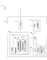
- FIG. 1 is a block diagram illustrating a schematic configuration of a GNSS receiver according to Embodiment 1.
- FIG. 3 is a flowchart illustrating an operation of the GNSS receiver according to the first embodiment.
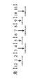
- FIG. 6 is a diagram for explaining a capacity reduction process for a plurality of files according to the first embodiment.
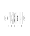
- 4 is a flowchart illustrating an ionospheric delay amount calculation process according to the first embodiment.
- 6 is a block diagram illustrating a schematic configuration of a GNSS receiver according to a second embodiment.
- FIG. It is a conceptual diagram which shows the state between a receiver and a satellite.
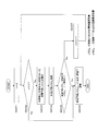
- 6 is a flowchart illustrating an ionospheric delay amount calculation process according to the second embodiment. It is a figure which shows the example of the ionosphere model of NeQuick.
- the main variables used in NeQuick are shown.
- the main parameters and units used in NeQuick are shown below.
- Embodiment 1 In the first embodiment, the NeQuick program is started in the GNSS receiver that receives the L1 wave signal from the Galileo satellite (1-frequency reception) and performs positioning of the receiver 1, and N The total amount of electrons (sTEC) using the eQuick ionosphere model is calculated, and the ionospheric delay is calculated. In the present embodiment, the GNSS receiver reduces the amount of spatial calculation when calculating the ionospheric delay amount within an appropriate range.
- FIG. 1 shows a schematic configuration of a receiver 1 according to the present embodiment.
- the receiver 1 includes an antenna 2, an L1 receiving unit 11, a data processing unit 12, an output unit 14, An input unit 15 and a memory 16 are provided.
- the antenna 2 receives a high-frequency signal (L1 wave signal) transmitted from the satellite 5 (FIG. 3).
- the L1 receiving unit 11 down-converts the high-frequency signal from the antenna 2 to an intermediate frequency, or converts the analog signal into a digital signal and converts it into a signal format that can be processed by the next data processing unit 12. .
- the data processing unit 12 inputs a data signal and a clock signal from the L1 receiving unit 11, decodes the data signal, and measures the position of the receiver 1.
- the data processing unit 12 includes a positioning calculation unit (positioning device) 13.
- the positioning calculation unit 13 includes a pseudo distance measurement unit 13a, an ionosphere delay amount calculation unit 13b, a pseudo process correction unit 13c, and a CCIR file processing unit 13d.
- the pseudo distance measuring unit 13a measures the pseudo distance from the time difference between the time of the data transmitted from the satellite 5 and the reception time of the same data received by the receiver 1.
- the ionosphere delay amount calculation unit 13b starts the NeQuick program and calculates the ionosphere delay amount based on a processed CCIR file and various parameters described later.
- the pseudo distance correction unit 13c corrects the pseudo distance by the ionosphere delay amount calculated by the ionosphere delay amount calculation unit 13b, and performs a positioning calculation.
- the pseudo distance correction unit 13c corrects the pseudo distance with respect to errors other than the ionospheric delay amount (for example, tropospheric delay and clock error), but the description thereof is omitted here.
- the CCIR file processing unit 13d is stored in advance in the memory 16 (processed CCIR file storage unit).
- the processed CCIR file is created by performing a capacity reduction process on the CCIR file stored in (the CCIR file before processing) as described later.
- the output unit 14 includes a display device, and outputs and displays position information of the receiver 1 obtained from the positioning result.
- the input unit 15 receives input of information by a user operation such as a touch panel or a push button.
- the memory 16 includes a RAM, a ROM, and the like, and stores various data, programs including NeQuick, a processed CCIR file to be described later, and the like.
- the number of memories 16 is not limited, and any form of internal memory, external memory, or both may be used.
- the positioning calculation unit 13, the data processing unit 12, and the L1 receiving unit 11 may be configured as a one-chip integrated circuit, or may be configured as separate chips.
- the configuration of the receiver 1 may be configured by either a single device or a plurality of devices.
- FIG. 2 is a flowchart showing the operation of the receiver 1 according to this embodiment.
- the antenna 2 of the receiver 1 receives a signal from the satellite, and the signal is sent from the L1 receiver 1 1 is converted into a predetermined data signal.
- the pseudo distance measurement unit 13a of the positioning calculation unit 13 measures the pseudo distance from the time difference between the time of the data transmitted from the satellite and the reception time of the same data received by the receiver 1.
- the NeQuick program is started by the ionosphere delay amount calculation unit 13b.
- the ionospheric delay amount is calculated as will be described later.
- the pseudo distance correction unit 13c corrects the pseudo distance according to the ionospheric delay amount.
- the CCIR file processing unit 13d reduces the capacity of the CCIR file used for calculating the ionospheric delay amount as follows. ⁇ 1.3.1 Capacity reduction processing for each file>
- a CCIR file one value is expressed in 32 bits, and about 11.4 bytes (32 bits ⁇ 2858) are required per file (for one month).
- the present inventor considered that even if each value of the CCIR file is expressed by half 16 bits, there is no significant influence on the ionospheric delay amount as a result. Therefore, each value of the CCIR file is expressed by 16 bits so that the integer part does not overflow. By reducing the number of bits of each value of the CCIR file from 32 bits to 16 bits, the amount of space calculation was reduced to about half.
- Table 1 below shows the rounding error of the ionospheric delay when each value of the CCIR file is expressed by 16 bits.
- the ionospheric delay amount (Original) calculated based on the conventional CCIR file in which each value is expressed in 32 bits and the CC in which each value is expressed in 16 bits.
- the ionospheric delay amount (Reduced) calculated based on the IR file and the rounding error (Delta) of both ionospheric delay amounts are shown.
- FIG. 3 shows how to group them, that is, how to group them.
- the values are summarized by taking the average value of the CCIR file of each group.
- the present invention is not limited to this, and may be summarized by taking representative values such as a median value and a mode value. .
- Table 2 shows how the CCIR files in Table 1 are grouped as described above (Reduced). It is the result of calculating the ionospheric delay for each month. Grouped CCIR files (processed C It is considered that the influence on the positioning result is small by using the (CIR file). From the above results, the data capacity of the processed CCIR file shown in Table 2 can be reduced to about 1/4 of that in the original case.
- the processed CCIR whose capacity has been reduced by the CCIR file processing unit 13d.
- the file is stored in the memory 16.
- FIG. 4 shows the contents of the ionospheric delay amount calculation process according to this embodiment.
- the ionosphere delay amount calculation unit 13b uses the NeQuick model for calculating the ionosphere delay amount, and causes the receiver 1 to execute the NeQuick program to calculate the ionosphere delay amount.
- n is an index n of the division number 2 n between the two points when integrating the total number of electrons sTEC between the satellite and the antenna.
- step S 1034 The total number of electrons sTEC N calculated in step S 1033 is stored in the memory 16. To store. Note that sTEC N is the total number of electrons when the number of divisions between two satellite-antenna points is 2n .
- the predetermined threshold Th is a threshold set in advance in the NeQuick program, and is set to a value that is small enough that the error of the ionospheric delay due to the number of divisions can be ignored (for example, 1/1000 of the previous value sTEC N-1 .
- step S1036 When it is determined in step S1035 that the error in the total number of electrons due to the number of divisions is less than the threshold Th, the total number of electrons is determined as sTEC N ⁇ 1 and the ionospheric delay amount is calculated ( Expression 1) and the result are output to the pseudo distance correction unit 13c.
- step S1037 If it is determined in step S1035 that the error in the total number of electrons due to the number of divisions is greater than or equal to the threshold Th, n is incremented and the process returns to step S1033.
- the receiver 1 that has started the NeQuick program uses a processed CCIR file with a reduced capacity when calculating the ionosphere delay amount by the ionosphere delay amount calculator 13 b of the positioning calculator 13. Thereby, the memory space required for the calculation of the ionosphere delay amount by the ionosphere delay amount calculation unit 13b can be reduced, and the amount of space calculation in the receiver 1 is greatly reduced.
- the CCIR file processing unit 13d performs the data reduction process on the CCIR file in advance and stores it in the memory 16 as the processed CCIR file.
- the present embodiment is not limited to this.
- the reduction process for the CCIR file can be sequentially performed when the ionosphere delay amount calculation unit 13b calculates the ionosphere delay amount.
- FIG. 5 shows a schematic configuration of the receiver 1 ′ according to the present embodiment.
- the configuration of the GNSS receiver 1 ′ is the same as that of the first embodiment (FIG.
- the GNSS receiver 1 ′ operates in the same manner as in the first embodiment (FIG. 2) except for the content of ionospheric delay amount calculation processing described later.
- ⁇ 2.3 Calculation of ionospheric delay> Hereinafter, the ionospheric delay amount calculation processing by the ionosphere delay amount calculation unit 13b ′ according to the present embodiment will be described in detail.
- the ionospheric delay amount was calculated under the conditions shown in Table 3 below.
- a satellite located in the east direction with an elevation angle of about 6 degrees is assumed.
- Table 4 shows the ionospheric delay (Origin) calculated by the conventional NeQuick program. For al), the ionospheric delay amount (Reduced) when the upper limit of the division number of the integral operation is set according to the present embodiment, and the rounding error (Delta) of both ionospheric delay amounts are shown.
- the NeQuick program if the difference between the total number of electrons calculated by the number of divisions 2 n-1 and the total number of electrons calculated by the number of divisions 2 n is less than a predetermined threshold Th, The number is determined to be 2 n-1 and the ionospheric delay is calculated.
- the ionospheric delay amount calculated by the finally determined division number 2 n ⁇ 1 is 71.037 m.
- Table 4 assumes that the solar activity is active and a low elevation satellite in the daytime, so that a considerably large amount of ionospheric delay occurs.
- the ionospheric delay amount according to the present embodiment has an error within 1 m as compared with the calculation based on the conventional NeQuick program. Therefore, it can be seen that a sufficient measurement system can be secured even if the number of divisions is “8” and the ionospheric delay amount is obtained.
- the amount of time calculation can be reduced by providing the upper limit of the number of divisions.
- FIG. 7 is a flowchart showing the contents of the calculation process (step 103 in FIG. 2) by the ionosphere delay amount calculation unit 13b ′ according to the present embodiment.
- the ionospheric delay amount is calculated by The NeQuick program is executed in the receiver 1 ′, and the ionospheric delay amount is calculated based on the NeQuick model.
- n is the total number of electrons sT between two points of the satellite and the antenna.
- the index n is the number of divisions 2n between the two points.
- n 2.
- the lower limit of the number of divisions between the two satellite-antenna points is 2 2. It is said. Note that the lower limit of the number of divisions is set in advance by the ionosphere delay amount calculation unit 13b ′.
- S2032 It is determined whether n ⁇ 4.
- the satellite - is set to the 2 3 maximum division number between two points of the antenna. Therefore, if n ⁇ 4 is not satisfied, the process proceeds to step S2036 to determine the ionospheric delay amount. If n ⁇ 4 is satisfied, the process proceeds to S2033 and the integration is continued.
- the upper limit of the number of divisions is set in advance by the ionosphere delay amount calculation unit 13b ′.
- step S2034 The total number of electrons sTEC N calculated in step S2033 is stored in the memory. Note that sTEC N is the total number of electrons when the number of divisions between two satellite-antenna points is 2n .
- the predetermined threshold Th is a threshold set in advance in the NeQuick program, and is set to a value that is small enough that the error of the ionospheric delay due to the number of divisions can be ignored (for example, 1/1000 of the previous value sTEC N-1 .
- step S2037 If it is determined in step S2035 that the error in the total number of electrons due to the number of divisions is equal to or greater than the threshold value Th, n is incremented and the process returns to step S2032.
- the content of the process by the said ionosphere delay part 13b ' is an example, and the order and setting of each process are not limited above.
- dividing the number 2 n is not an upper limit 2 3, may be increased or decreased depending on the conditions.
- the initial value of n is not limited to 2, for example, 3 ( That is, the integral value is obtained only once).
- the upper limit and / or lower limit of the number of divisions can be set sequentially when calculating the ionospheric delay amount.
- the ionosphere delay amount calculation unit 13b ′ determines the upper limit and / or the lower limit of the number of divisions for each process in FIG.
- a plurality of upper and / or lower limits of the number of divisions may be set according to positioning conditions such as each satellite, each absolute value of the delay amount, reception position, positioning time, solar activity, time, and the like.
- an upper limit and / or a lower limit of a plurality of division numbers may be stored in advance, and the number of divisions corresponding to similar conditions may be selected to calculate the ionospheric delay amount.
- Test 1 and Test 2 were satellites located in the south, two patterns of high and low elevation angles were set, respectively, and estimation errors for both daytime and nighttime were calculated.
- Tests 3 and 4 were satellites located in the east direction, and two patterns of high and low elevation angles were set. Similarly, estimation errors for both daytime and nighttime were calculated.
- Table 6 shows the estimation error in each R12. Note that the absolute value of the ionospheric delay amount is considered to vary depending on the value of R12, and the estimation error also tends to vary depending on R12. R12 to “2 Although the error was the largest when "01.3" was set, it was estimated that the maximum was about 1 m and about 1 m was about 0.2 m.
- the GNSS receiver calculates the ionospheric delay amount according to both the first and second embodiments.
- Receiver configuration The configuration of the GNSS receiver according to the present embodiment is the same as that of the first embodiment (FIG. 1).
- the ionosphere delay amount calculation unit 13b includes: Read the processed CCIR file (Embodiment 1; Step S1031 in FIG. 4), An upper limit is set to the number of divisions when integrating the total number of electrons between the two points of the satellite-antenna, and the ionospheric delay amount is calculated (second embodiment; steps S2031 to S2037 in FIG. 7).
- the CCIR file processing unit 13d may sequentially perform reduction processing on the CCIR file when the ionosphere delay amount calculation unit 13b calculates the ionosphere delay amount. .
- the CCIR file processing unit 13d may sequentially perform reduction processing on the CCIR file when the ionosphere delay amount calculation unit 13b calculates the ionosphere delay amount. .
- the receiver 1 that has started the NeQuick program integrates the total number of electrons by the ionosphere delay amount calculation unit 13b of the positioning calculation unit 13, the upper limit of the number of divisions between the two satellite-antenna points is set. Provided, and a processed CCIR file with a further reduced capacity is used.
- Embodiments of the present invention are not limited to the above-described embodiments, and various modifications, changes, and combinations are possible without departing from the spirit of the present invention.
- the above-described embodiments are essentially preferable examples, and are not intended to limit the scope of the present invention, its application, or its use.
- the present invention can also be implemented as a positioning method or a computer program using a processor or a memory.
- the present invention can also be implemented as an information terminal device (including a mobile terminal device) provided with the integrated circuit.
Landscapes
- Engineering & Computer Science (AREA)
- Radar, Positioning & Navigation (AREA)
- Remote Sensing (AREA)
- Computer Networks & Wireless Communication (AREA)
- Physics & Mathematics (AREA)
- General Physics & Mathematics (AREA)
- Position Fixing By Use Of Radio Waves (AREA)
Abstract
【課題】GNSS受信機における電離層遅延量の演算ためのメモリ空間を減らし、空間計算量を削減する。 【解決手段】測位装置13は、測位用衛星5とアンテナ2間の擬似距離を測定する擬似距離測定部13aと、擬似距離に含まれる電離層遅延量を演算する電離層遅延量演算部13bと、電離層遅延量に基づき擬似距離を補正することにより測位演算を行う擬似距離補正部13cと、異なる月にそれぞれ対応する複数のCCIRファイルを所定の条件に応じてまとめた処理済CCIRファイルを記憶する処理済CCIRファイル記憶部16とを備える。電離層遅延量演算部13bは、処理済CCIRファイルに基づき電離層遅延量を演算する。
Description
本発明は、NeQuick等の電離層モデルを用いて電離層遅延量を演算し、測位を行
う技術に関する。
う技術に関する。
電波が電離層を通過するとき、電波の速度は、電子密度に比例し、電波の周波数の二乗
に反比例する量だけ遅くなる(電離層遅延)。この電離層による電離層遅延量Diono
[m]は、次の数式1により導かれる。
に反比例する量だけ遅くなる(電離層遅延)。この電離層による電離層遅延量Diono
[m]は、次の数式1により導かれる。

ぶ視線上にある自由電子の総数(総電子量)であり、単位はTECU(TEC unit)である
。なお、1TECUは、視線に沿った底面積1m2あたり1016個の電子が含まれるこ
とを意味する。
従来、この電離層遅延量による誤差を補正するため、Klobucharモデル、IR
I(International Reference onosphere)、Bentモデル、電離層のE,F1,F2
層に基づいて電子密度を計算するDGRの概念等の電離層モデルを用いることが提案され
ている。
I(International Reference onosphere)、Bentモデル、電離層のE,F1,F2
層に基づいて電子密度を計算するDGRの概念等の電離層モデルを用いることが提案され
ている。
特に、民生ベースのGNSS(Global Navigation Satellite Systems)として、欧州
によって開発され近々運用が予定されているガリレオ測位衛星システムにおいては、電離
層モデルとして、ITU-Rにより推奨されているNeQuickモデルが使用される。
によって開発され近々運用が予定されているガリレオ測位衛星システムにおいては、電離
層モデルとして、ITU-Rにより推奨されているNeQuickモデルが使用される。
NeQuickモデルは、電離層のうちエピスタイン層(E,F1,F2層)の形態に
基づき、所定の月、地理緯度及び経度、高さ及びユニバーサルタイムにおける電子密度を
積分して表したものである(非特許文献1を参照)。
基づき、所定の月、地理緯度及び経度、高さ及びユニバーサルタイムにおける電子密度を
積分して表したものである(非特許文献1を参照)。
図8は、NeQuickの電離層モデルの一例を示す。NeQuickの電離層モデル
は、高さ[km]に対する電子密度の分布特性が示す。同電離層モデルによれば、E層、
F1層及びF2層を上下に分割し、F2層のピークより下をボトムサイド、F2層のピー
クより上をトップサイドとする。また、NeQuickにおいて使用される主な変数は、
図9Aに示し、NeQuickで用いられる主なパラメータ及び単位は、図9Bに示す。
NeQuickモデルは、これらの変数及びパラメータを用いて作成される。なお、計算
の詳細は、非特許文献1のAPPENNDIX A.2やA.3に示す通りである。
このNeQuickモデルを用いて、最終的には、電波経路に沿ったsTEC(Slant
TEC)を得る。なお、sTECは、衛星の仰角変化に伴って視線ベクトルが貫通する電離
層の厚さが変化するときの斜めに視線が貫く場合のTECである。
は、高さ[km]に対する電子密度の分布特性が示す。同電離層モデルによれば、E層、
F1層及びF2層を上下に分割し、F2層のピークより下をボトムサイド、F2層のピー
クより上をトップサイドとする。また、NeQuickにおいて使用される主な変数は、
図9Aに示し、NeQuickで用いられる主なパラメータ及び単位は、図9Bに示す。
NeQuickモデルは、これらの変数及びパラメータを用いて作成される。なお、計算
の詳細は、非特許文献1のAPPENNDIX A.2やA.3に示す通りである。
このNeQuickモデルを用いて、最終的には、電波経路に沿ったsTEC(Slant
TEC)を得る。なお、sTECは、衛星の仰角変化に伴って視線ベクトルが貫通する電離
層の厚さが変化するときの斜めに視線が貫く場合のTECである。
なお、NeQuickモデルにより提供されるTECは、月平均の値であり、この月平
均の値は、CCIRファイルとして受信機側に配布される。受信機側においては、CCI
Rファイルやその他のパラメータを用いて、日単位の電離層遅延量を演算する。
均の値は、CCIRファイルとして受信機側に配布される。受信機側においては、CCI
Rファイルやその他のパラメータを用いて、日単位の電離層遅延量を演算する。
Bidaine, "Ionosphere Crossing of GALILEO Signals", Master thesis, Belgium, University of Liege, 26-June-2006, P120
GNSS受信機においてNeQuick等を利用して電離層遅延量を計算する場合、電
子密度を求めるために必要なデータ量が膨大である。特に、受信機は、電離層遅延量の計
算に必要なCCIRファイルを有している。
子密度を求めるために必要なデータ量が膨大である。特に、受信機は、電離層遅延量の計
算に必要なCCIRファイルを有している。
CCIRファイルは、地球磁場における位置(position)、季節(season)、太陽活動
(solar activity)、時間(time-of-day)等の、電離層を形成する一般的な変動因子の
値を月毎(1月から12月)にまとめたファイルである。
(solar activity)、時間(time-of-day)等の、電離層を形成する一般的な変動因子の
値を月毎(1月から12月)にまとめたファイルである。
従って、受信機には大きなメモリ空間が必要になり、空間計算量が膨大になるという問
題があった。
題があった。
そこで、本発明は、GNSS受信機における電離層遅延量の演算ためのメモリ空間を減
らし、空間計算量を削減することを目的とする。
らし、空間計算量を削減することを目的とする。
上記目的を達成するため、本発明の一つの観点によれば、測位用衛星からGNSS受信
機のアンテナにより受信した信号に基づき測位を行う測位装置であって、擬似距離測定部
と、電離層遅延量演算部と、擬似距離補正部と、処理済CCIRファイル記憶部とを備え
る測位装置が提供される。擬似距離測定部は、測位用衛星とアンテナ間の擬似距離を測定
する。電離層遅延量演算部は、擬似距離に含まれる電離層遅延量を演算する。擬似距離補
正部は、電離層遅延量に基づき擬似距離を補正することにより測位演算を行う。処理済C
CIRファイル記憶部は、異なる月にそれぞれ対応する複数のCCIRファイルを所定の
条件に応じてまとめた処理済CCIRファイルを記憶する。電離層遅延量演算部は、処理
済CCIRファイルに基づき電離層遅延量を演算する。
機のアンテナにより受信した信号に基づき測位を行う測位装置であって、擬似距離測定部
と、電離層遅延量演算部と、擬似距離補正部と、処理済CCIRファイル記憶部とを備え
る測位装置が提供される。擬似距離測定部は、測位用衛星とアンテナ間の擬似距離を測定
する。電離層遅延量演算部は、擬似距離に含まれる電離層遅延量を演算する。擬似距離補
正部は、電離層遅延量に基づき擬似距離を補正することにより測位演算を行う。処理済C
CIRファイル記憶部は、異なる月にそれぞれ対応する複数のCCIRファイルを所定の
条件に応じてまとめた処理済CCIRファイルを記憶する。電離層遅延量演算部は、処理
済CCIRファイルに基づき電離層遅延量を演算する。
ここでは、GNSS受信機における電離層遅延量の演算ためのメモリ空間を減らし、空
間計算量を削減することができる。
間計算量を削減することができる。
上記測位装置は、異なる月にそれぞれ対応する複数のCCIRファイルを所定の条件に
応じてまとめることにより上記処理済CCIRファイルを作成するCCIRファイル処理
部を更に備え、同CCIRファイル処理部は更に、複数のCCIRファイルのビット数を
削減することにより処理済CCIRファイルを作成してもよい。
応じてまとめることにより上記処理済CCIRファイルを作成するCCIRファイル処理
部を更に備え、同CCIRファイル処理部は更に、複数のCCIRファイルのビット数を
削減することにより処理済CCIRファイルを作成してもよい。
上記測位装置はまた、異なる月にそれぞれ対応する複数のCCIRファイルを所定の条
件に応じてまとめることにより上記処理済CCIRファイルを作成するCCIRファイル
処理部を更に備え、同CCIRファイル処理部は、複数のCCIRファイルのうち、値の
差が所定値以下の異なるCCIRファイルをまとめることにより処理済ファイルを作成し
てもよい。
件に応じてまとめることにより上記処理済CCIRファイルを作成するCCIRファイル
処理部を更に備え、同CCIRファイル処理部は、複数のCCIRファイルのうち、値の
差が所定値以下の異なるCCIRファイルをまとめることにより処理済ファイルを作成し
てもよい。
ここで、値の差が所定値以下の異なるCCIRファイルをまとめるとは、例えば、平均
値、中央値、最頻値等の代表値をとることを含む。
値、中央値、最頻値等の代表値をとることを含む。
上記測位装置はまた、異なる月にそれぞれ対応する複数のCCIRファイルを所定の条
件に応じてまとめることにより上記処理済CCIRファイルを作成するCCIRファイル
処理部を更に備え、同CCIRファイル処理部は、電離層遅延量演算部が電離層遅延量の
演算を行う毎に、処理済CCIRファイルを作成するようにしてもよい。
件に応じてまとめることにより上記処理済CCIRファイルを作成するCCIRファイル
処理部を更に備え、同CCIRファイル処理部は、電離層遅延量演算部が電離層遅延量の
演算を行う毎に、処理済CCIRファイルを作成するようにしてもよい。
本発明の別の観点によれば、上記測位装置と、測位用衛星からの信号を受信するアンテ
ナとを備えるGNSS受信機が提供される。
ナとを備えるGNSS受信機が提供される。
本発明の更に別の観点によれば、上記GNSS受信機を備える情報端末機器が提供され
る。
る。
本発明の更に別の観点によれば、測位用衛星からGNSS受信機のアンテナにより受信
した信号に基づき測位を行う測位方法であって、測位用衛星とアンテナ間の擬似距離を測
定する擬似距離測定ステップと、擬似距離に含まれる電離層遅延量を演算する電離層遅延
量演算ステップと、電離層遅延量に基づき擬似距離を補正することにより測位演算を行う
擬似距離ステップと、異なる月にそれぞれ対応する複数のCCIRファイルを所定の条件
に応じてまとめることにより処理済CCIRファイルを作成するCCIRファイル処理ス
テップとを備える測位方法が提供される。この場合、電離層遅延量演算ステップにおいて
は、処理済CCIRファイルに基づき電離層遅延量を演算する。
した信号に基づき測位を行う測位方法であって、測位用衛星とアンテナ間の擬似距離を測
定する擬似距離測定ステップと、擬似距離に含まれる電離層遅延量を演算する電離層遅延
量演算ステップと、電離層遅延量に基づき擬似距離を補正することにより測位演算を行う
擬似距離ステップと、異なる月にそれぞれ対応する複数のCCIRファイルを所定の条件
に応じてまとめることにより処理済CCIRファイルを作成するCCIRファイル処理ス
テップとを備える測位方法が提供される。この場合、電離層遅延量演算ステップにおいて
は、処理済CCIRファイルに基づき電離層遅延量を演算する。
本発明の更に別の観点によれば、上記測位方法をコンピュータに実行させるプログラム
が提供される。
が提供される。
本発明によれば、GNSS受信機における電離層遅延量の演算ためのメモリ空間を減ら
し、空間計算量を削減することができる。
し、空間計算量を削減することができる。
<1.実施形態1>
実施形態1においては、ガリレオ衛星からのL1波の信号を受信し(1周波受信)、受
信機1の測位を行うGNSS受信機において、NeQuickプログラムを起動させ、N
eQuick電離層モデルを用いた総電子量(sTEC)を算出し、電離層遅延量を計算
する。本実施形態においては、GNSS受信機は、電離層遅延量の演算の際の空間計算量
を適度な範囲で削減する。
<1.1 受信機の構成>
図1は、本実施形態に係る受信機1の概略構成を示す。
実施形態1においては、ガリレオ衛星からのL1波の信号を受信し(1周波受信)、受
信機1の測位を行うGNSS受信機において、NeQuickプログラムを起動させ、N
eQuick電離層モデルを用いた総電子量(sTEC)を算出し、電離層遅延量を計算
する。本実施形態においては、GNSS受信機は、電離層遅延量の演算の際の空間計算量
を適度な範囲で削減する。
<1.1 受信機の構成>
図1は、本実施形態に係る受信機1の概略構成を示す。
受信機1は、アンテナ2と、L1受信部11と、データ処理部12と、出力部14と、
入力部15と、メモリ16とを備える。
入力部15と、メモリ16とを備える。
アンテナ2は、衛星5(図3)から送出される高周波信号(L1波の信号)を受信する
。
。
L1受信部11は、アンテナ2からの高周波信号を中間周波数にダウン・コンバートし
たり、アナログ信号をデジタル信号に変換して、次のデータ処理部12で処理できるよう
な信号フォーマットに変換したりする。
たり、アナログ信号をデジタル信号に変換して、次のデータ処理部12で処理できるよう
な信号フォーマットに変換したりする。
データ処理部12は、L1受信部11よりデータ信号とクロック信号を入力し、データ
信号をデコードしたり、受信機1の位置の測位を行う。データ処理部12は、測位演算部
(測位装置)13を含む。
信号をデコードしたり、受信機1の位置の測位を行う。データ処理部12は、測位演算部
(測位装置)13を含む。
測位演算部13は、擬似距離測定部13aと、電離層遅延量演算部13bと、擬似処理
補正部13cと、CCIRファイル処理部13dとを含む。
補正部13cと、CCIRファイル処理部13dとを含む。
擬似距離測定部13aは、衛星5から送られたデータの時刻と受信機1が受信した同デ
ータの受信時刻との時間差から擬似距離を測定する。
ータの受信時刻との時間差から擬似距離を測定する。
電離層遅延量演算部13bは、後述するように、NeQuickプログラムを起動させ
、後述する処理済CCIRファイルや各種パラメータに基づいて電離層遅延量を算出する
。
、後述する処理済CCIRファイルや各種パラメータに基づいて電離層遅延量を算出する
。
擬似距離補正部13cは、電離層遅延量演算部13bにより算出された電離層遅延量に
よって擬似距離を補正し、測位演算を行う。なお、擬似距離補正部13cでは、電離層遅
延量以外の誤差(例えば、対流圏遅延や時計誤差分等)に関しても擬似距離を補正するが
、ここでは説明を省略する。
よって擬似距離を補正し、測位演算を行う。なお、擬似距離補正部13cでは、電離層遅
延量以外の誤差(例えば、対流圏遅延や時計誤差分等)に関しても擬似距離を補正するが
、ここでは説明を省略する。
CCIRファイル処理部13dは、予めメモリ16(処理済CCIRファイル記憶部)
に格納されたCCIRファイル(処理前のCCIRファイル)について、後述するように
容量の削減処理を行うことにより、処理済CCIRファイルを作成する。
に格納されたCCIRファイル(処理前のCCIRファイル)について、後述するように
容量の削減処理を行うことにより、処理済CCIRファイルを作成する。
出力部14は、表示装置を含み、測位結果により得られた受信機1の位置情報の出力や
表示を行う。
表示を行う。
入力部15は、タッチパネルやプッシュボタン等ユーザの操作により情報の入力を受け
付ける。
付ける。
メモリ16は、RAMやROM等からなり、各種データやNeQuickを含む各プロ
グラムや後述する処理済CCIRファイル等を格納する。なお、メモリ16の数は限定さ
れず、内部メモリ又は外部メモリ、或いはその双方のいずれの形態であってもよい。
グラムや後述する処理済CCIRファイル等を格納する。なお、メモリ16の数は限定さ
れず、内部メモリ又は外部メモリ、或いはその双方のいずれの形態であってもよい。
なお本実施形態においては、例えば、測位演算部13、データ処理部12及びL1受信
部11は1チップの集積回路として構成してもよいし、それぞれ別々のチップで構成して
もよい。また、受信機1の構成も、単一の装置又は複数の装置のいずれによって構成され
ていてもよい。
部11は1チップの集積回路として構成してもよいし、それぞれ別々のチップで構成して
もよい。また、受信機1の構成も、単一の装置又は複数の装置のいずれによって構成され
ていてもよい。
なお、CCIRファイル(又は、CCIRマップ)は、地球磁場における位置(positi
on)、季節(season)、太陽活動(solar activity)、時間(time-of-day)等の、電離
層を形成する一般的な変動因子の値を月毎(1月から12月)にまとめたファイルである
。
<1.2 受信機の動作>
図2は、本実施形態に係る受信機1の動作を示すフローチャートである。
on)、季節(season)、太陽活動(solar activity)、時間(time-of-day)等の、電離
層を形成する一般的な変動因子の値を月毎(1月から12月)にまとめたファイルである
。
<1.2 受信機の動作>
図2は、本実施形態に係る受信機1の動作を示すフローチャートである。
S101:受信機1のアンテナ2は、衛星より信号を受信し、同信号は、L1受信部1
1により所定のデータ信号に変換される。
1により所定のデータ信号に変換される。
S102:測位演算部13の擬似距離測定部13aにより、衛星から送られたデータの
時刻と受信機1が受信した同データの受信時刻との時間差から擬似距離を測定する。
時刻と受信機1が受信した同データの受信時刻との時間差から擬似距離を測定する。
S103:電離層遅延量演算部13bにより、NeQuickプログラムを起動させ、
後述するように電離層遅延量を演算する。
後述するように電離層遅延量を演算する。
S104:擬似距離補正部13cにより、電離層遅延量に応じて擬似距離を補正する。
S105:擬似距離を補正して測位演算を行い、その結果を出力部14により出力・表
示する。
<1.3 電離層遅延量の演算処理>
以下において、本実施形態に係る電離層遅延量演算部13bによる電離層遅延量の演算
処理について詳細に説明する。
示する。
<1.3 電離層遅延量の演算処理>
以下において、本実施形態に係る電離層遅延量演算部13bによる電離層遅延量の演算
処理について詳細に説明する。
CCIRファイル処理部13dは、電離層遅延量の演算に用いられるCCIRファイル
の容量を次のようにして削減する。
<1.3.1 各ファイルの容量削減処理>
従来、CCIRファイルにおいては、1つの値は32bitで表現されており、1ファ
イル(一月分)あたり、約11.4byte(32bit ×2858)が必要となる。し
かし、本願発明者は、CCIRファイルの各値を、半分の16bitで表現しても、結果
的に電離層遅延量に対する大きな影響はないものと考えた。そこで、CCIRファイルの
各値を、整数部がオーバーフローしないように16bitで表現した。CCIRファイル
の各値のビット数を32bitから16bitに削減することにより、空間計算量を約半
分に削減した。
の容量を次のようにして削減する。
<1.3.1 各ファイルの容量削減処理>
従来、CCIRファイルにおいては、1つの値は32bitで表現されており、1ファ
イル(一月分)あたり、約11.4byte(32bit ×2858)が必要となる。し
かし、本願発明者は、CCIRファイルの各値を、半分の16bitで表現しても、結果
的に電離層遅延量に対する大きな影響はないものと考えた。そこで、CCIRファイルの
各値を、整数部がオーバーフローしないように16bitで表現した。CCIRファイル
の各値のビット数を32bitから16bitに削減することにより、空間計算量を約半
分に削減した。
次の表1は、CCIRファイルの各値を16bitで表現した場合の電離層遅延量の丸
め誤差を示す。なお、表1においては、各値を32bitで表現した従来のCCIRファ
イルに基づいて計算した電離層遅延量(Original)と、各値を16bitで表現したCC
IRファイルに基づいて計算した電離層遅延量(Reduced)と、双方の電離層遅延量の丸
め誤差(Delta)を示している。
め誤差を示す。なお、表1においては、各値を32bitで表現した従来のCCIRファ
イルに基づいて計算した電離層遅延量(Original)と、各値を16bitで表現したCC
IRファイルに基づいて計算した電離層遅延量(Reduced)と、双方の電離層遅延量の丸
め誤差(Delta)を示している。
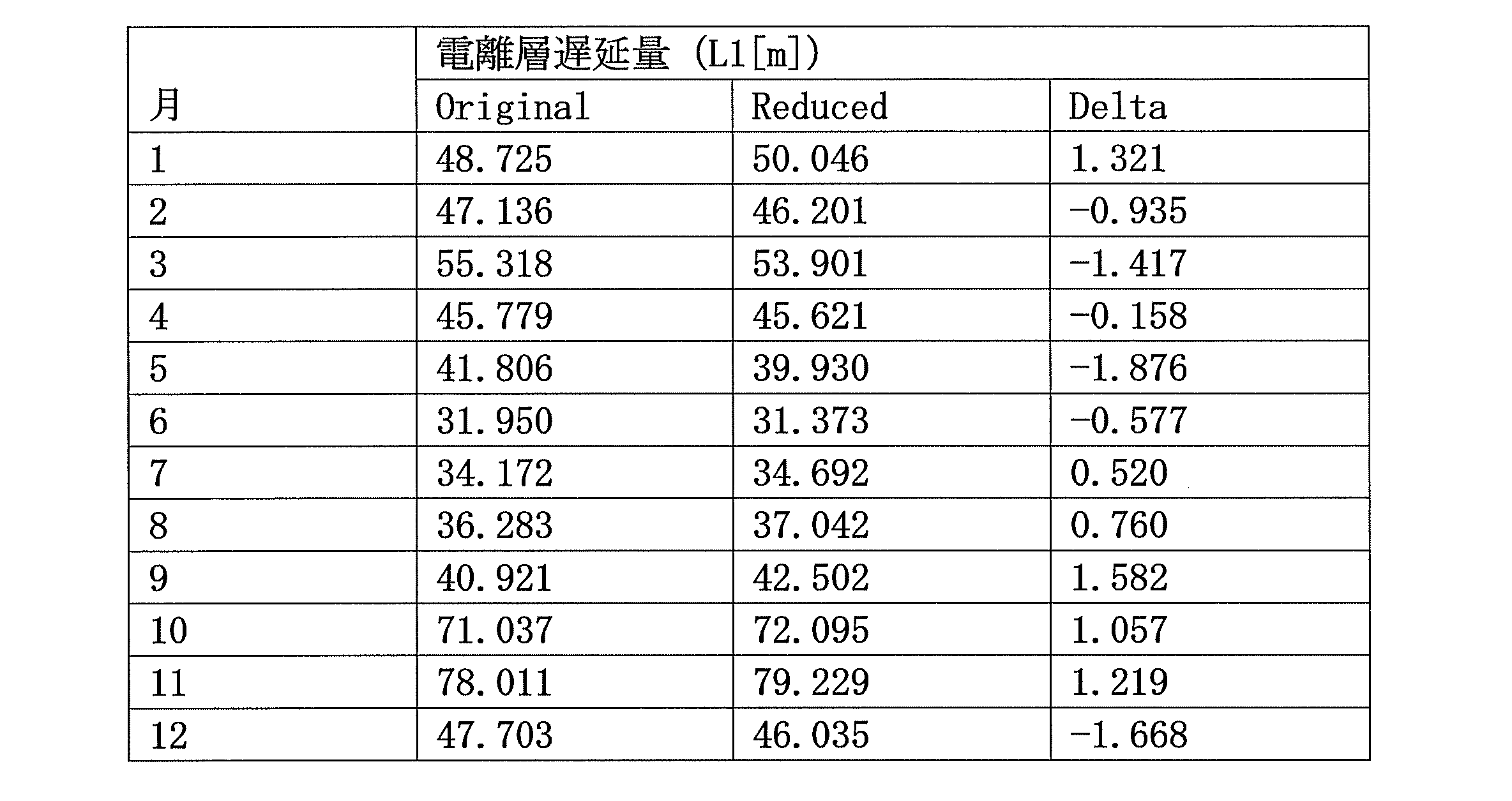
用いる場合とReducedのCCIRファイル(処理済CCIRファイル)を用いる場合とは
、2m以内の丸め誤差であった。よって、CCIRファイルの各値を16bitによって
表現しても、算出される電離層遅延量には大きな影響はないことが実証された。
<1.3.2 ファイル数の削減処理>
上記の通り、CCIRファイルは月単位のデータであり、全部で12ファイル存在する
。上記のように各値を16bitにして削減し半分の容量になったとしても、依然68.
6byte必要である。そこで、本願発明者は、更にこれらのファイルの容量を、電離層
遅延量に影響を与えない範囲で削減することを検討した。
具体的には、これら月毎のファイルを幾つかにまとめることにした。この場合、できる
だけ値の変化が小さい月の平均値をとり、それを1つのファイルにする。図3にそのまと
め方、つまりグルーピングのし方を示す。
だけ値の変化が小さい月の平均値をとり、それを1つのファイルにする。図3にそのまと
め方、つまりグルーピングのし方を示す。
図3に示すように、値の差が小さい、つまり値の差が所定値以下の異なる月のグループ
(12,1,2)、(3,4)、(5)、(6,7,8)、(9)、(10,11)をま
とめ、グループ毎に各値の平均値をとって、一つのファイルとする。これにより、ファイ
ル数は12から6に削減できる。
(12,1,2)、(3,4)、(5)、(6,7,8)、(9)、(10,11)をま
とめ、グループ毎に各値の平均値をとって、一つのファイルとする。これにより、ファイ
ル数は12から6に削減できる。
なお、本実施形態においては、各グループのCCIRファイルの値の平均値をとること
によりまとめているが、これに限られず、中央値、最頻値等の代表値をとることによりま
とめてもよい。
によりまとめているが、これに限られず、中央値、最頻値等の代表値をとることによりま
とめてもよい。
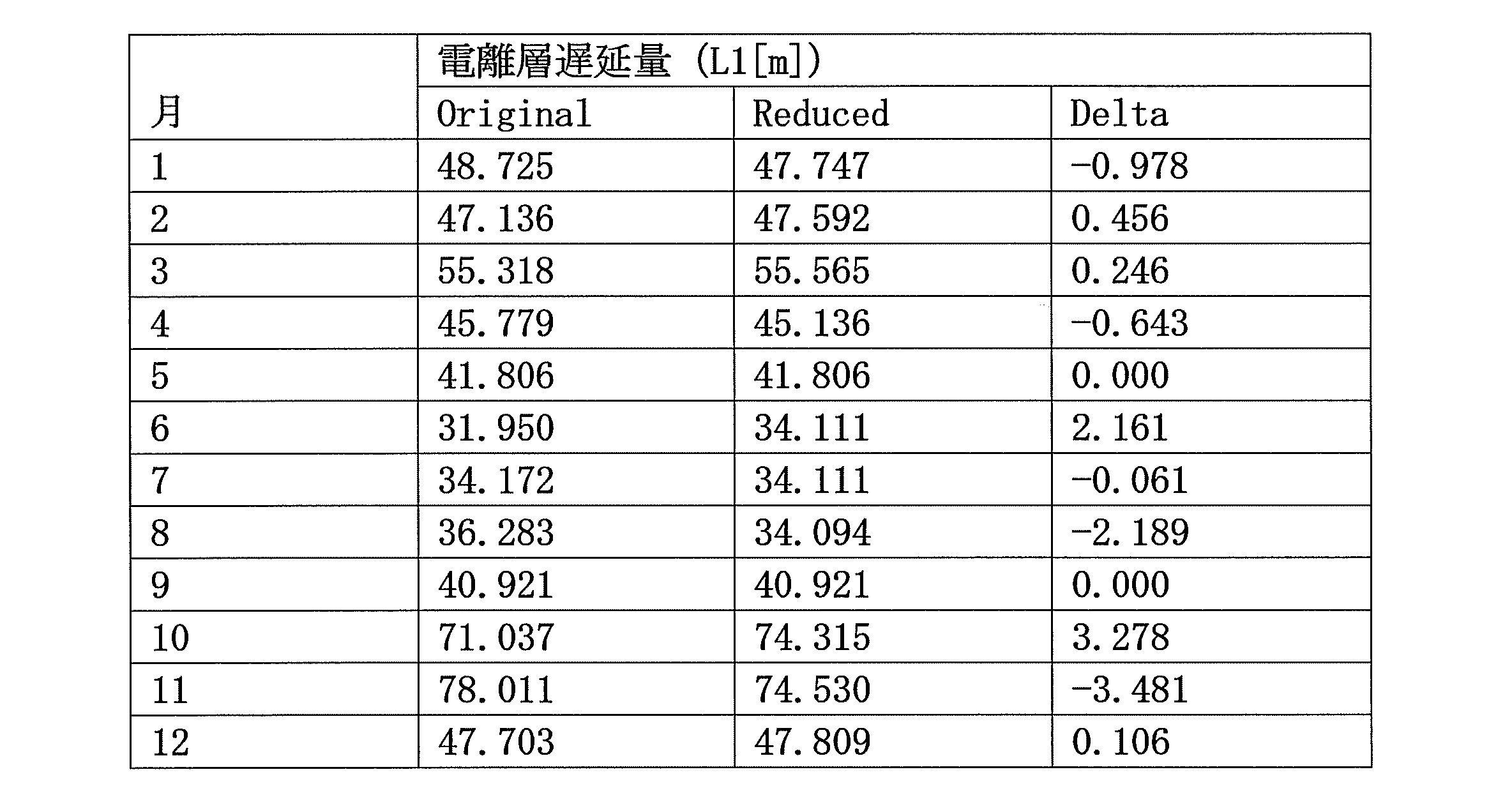
表2は、表1の各CCIRファイルを上記のようにグルーピングした後(Reduced)、
各月の電離層遅延量を求めた結果である。グルーピングしたCCIRファイル(処理済C
CIRファイル)を用いることにより、測位結果に与える影響は小さいと考えられる。以
上の結果から、表2に示す処理済CCIRファイルのデータ容量は、Original場合の概ね
1/4まで削減できたことになる。
各月の電離層遅延量を求めた結果である。グルーピングしたCCIRファイル(処理済C
CIRファイル)を用いることにより、測位結果に与える影響は小さいと考えられる。以
上の結果から、表2に示す処理済CCIRファイルのデータ容量は、Original場合の概ね
1/4まで削減できたことになる。
ファイルは、メモリ16に格納される。
なお、上記説明においては、各ファイルの容量削減処理と、ファイル数の削減処理とを
双方を行うとしているが、いずれか一方のみのであってもメモリ空間を削減できる。
<1.3.3 演算処理の内容>
図4は、本実施形態による電離層遅延量の演算処理の内容を示す。本実施形態による電
離層遅延量演算部13bは、電離層遅延量の計算にNeQuickモデルを利用し、受信
機1においてNeQuickプログラムを実行させて電離層遅延量を演算する。
双方を行うとしているが、いずれか一方のみのであってもメモリ空間を削減できる。
<1.3.3 演算処理の内容>
図4は、本実施形態による電離層遅延量の演算処理の内容を示す。本実施形態による電
離層遅延量演算部13bは、電離層遅延量の計算にNeQuickモデルを利用し、受信
機1においてNeQuickプログラムを実行させて電離層遅延量を演算する。
なお、フローチャートにおいて、nは、衛星―アンテナ間における総電子数sTECを
積分するに際して、同2点間の分割数2nの指数nである。
積分するに際して、同2点間の分割数2nの指数nである。
S1031:処理済CCIRファイルをメモリ16より読み出す。
S1032:n=2とする。ここでは、衛星―アンテナの2点間の分割数の下限を22
としている。
としている。
S1033:読み出した処理済CCIRファイルに基づき、分割数2nの場合の、衛星
―アンテナの2点間の総電子数sTECNを積分する。
―アンテナの2点間の総電子数sTECNを積分する。
S1034:ステップS1033において算出した総電子数sTECNを、メモリ16
に格納する。なお、sTECNは、衛星―アンテナの2点間の分割数を2nとした場合の
総電子数である。
に格納する。なお、sTECNは、衛星―アンテナの2点間の分割数を2nとした場合の
総電子数である。
S1035:総電子数sTECNと総電子数sTECN-1(メモリに格納された、分
割数2n-1のときの総電子数)との差分(絶対値)が、所定の閾値Th未満かどうかを
判断する。ここで、所定の閾値Thとは、NeQuickプログラムにおいて予め設定さ
れている閾値であって、分割数に因る電離層遅延量の誤差が無視できる程度に十分に小さ
い値に設定されている(例えば、前の値sTECN-1の1000分の1)。
割数2n-1のときの総電子数)との差分(絶対値)が、所定の閾値Th未満かどうかを
判断する。ここで、所定の閾値Thとは、NeQuickプログラムにおいて予め設定さ
れている閾値であって、分割数に因る電離層遅延量の誤差が無視できる程度に十分に小さ
い値に設定されている(例えば、前の値sTECN-1の1000分の1)。
S1036:ステップS1035において分割数に因る総電子数の誤差が閾値Th未満
であると判断された場合、総電子数をsTECN-1と決定し、電離層遅延量を演算し(
数式1)、結果を擬似距離補正部13cに出力する。
であると判断された場合、総電子数をsTECN-1と決定し、電離層遅延量を演算し(
数式1)、結果を擬似距離補正部13cに出力する。
S1037:ステップS1035において分割数に因る総電子数の誤差が閾値Th以上
であると判断された場合、nをインクリメントしてステップS1033に戻る。
であると判断された場合、nをインクリメントしてステップS1033に戻る。
なお、上記電離層遅延部13bによる処理の内容は一例であり、各処理の順序や設定は
上記に限定されるものではない。例えば、nの初期値は2に限定されない、例えば、3と
してもよい。
<1.4 実施形態1の効果>
上記実施形態においては、NeQuickのプログラムを起動させた受信機1は、測位
演算部13の電離層遅延量演算部13bにより電離層遅延量を演算するとき、容量を削減
した処理済のCCIRファイルを用いる。これにより、電離層遅延量演算部13bによる
電離層遅延量の計算に必要なメモリ空間を削減することができ、受信機1における空間計
算量は大幅に削減される。
<1.5 実施形態1の変形例>
上記説明においては、CCIRファイル処理部13dは、予めCCIRファイルに対す
るデータの削減処理を行い、処理済CCIRファイルとしてメモリ16に格納しておくと
したが、本実施形態はこれに限定されない。
上記に限定されるものではない。例えば、nの初期値は2に限定されない、例えば、3と
してもよい。
<1.4 実施形態1の効果>
上記実施形態においては、NeQuickのプログラムを起動させた受信機1は、測位
演算部13の電離層遅延量演算部13bにより電離層遅延量を演算するとき、容量を削減
した処理済のCCIRファイルを用いる。これにより、電離層遅延量演算部13bによる
電離層遅延量の計算に必要なメモリ空間を削減することができ、受信機1における空間計
算量は大幅に削減される。
<1.5 実施形態1の変形例>
上記説明においては、CCIRファイル処理部13dは、予めCCIRファイルに対す
るデータの削減処理を行い、処理済CCIRファイルとしてメモリ16に格納しておくと
したが、本実施形態はこれに限定されない。
CCIRファイルに対する削減処理は、電離層遅延量演算部13bによる電離層遅延量
の計算時に逐次行うことができる。
の計算時に逐次行うことができる。
この場合、図4の処理毎に、CCIRファイル処理部13dが上記各ファイルの容量削
減処理及びファイル数の削減処理の双方又は一方を行い、電離層遅延量演算部13bは作
成された処理済CCIRファイルに応じて電離層遅延量の演算を行う。
<2.実施形態2>
実施形態1においては、GNSS受信機は、電離層遅延量の演算の際の時間計算量を適
度な範囲で削減することにより、電離層遅延量の演算速度を速める。
<2.1 受信機の構成>
図5は、本実施形態に係る受信機1´の概略構成を示す。GNSS受信機1´の構成は
、CCIRファイル処理部13d及び処理済CCIRファイルを備えないことを除いては
、実施形態1(図1)と同様である。
<2.2 受信機の動作>
本実施形態に係るGNSS受信機1´は、後述する電離層遅延量の演算処理の内容を除
いては、実施形態1(図2)と同様に動作する。
<2.3 電離層遅延量の演算処理>
以下において、本実施形態に係る電離層遅延量演算部13b´による電離層遅延量の演
算処理について詳細に説明する。
減処理及びファイル数の削減処理の双方又は一方を行い、電離層遅延量演算部13bは作
成された処理済CCIRファイルに応じて電離層遅延量の演算を行う。
<2.実施形態2>
実施形態1においては、GNSS受信機は、電離層遅延量の演算の際の時間計算量を適
度な範囲で削減することにより、電離層遅延量の演算速度を速める。
<2.1 受信機の構成>
図5は、本実施形態に係る受信機1´の概略構成を示す。GNSS受信機1´の構成は
、CCIRファイル処理部13d及び処理済CCIRファイルを備えないことを除いては
、実施形態1(図1)と同様である。
<2.2 受信機の動作>
本実施形態に係るGNSS受信機1´は、後述する電離層遅延量の演算処理の内容を除
いては、実施形態1(図2)と同様に動作する。
<2.3 電離層遅延量の演算処理>
以下において、本実施形態に係る電離層遅延量演算部13b´による電離層遅延量の演
算処理について詳細に説明する。
従来、NeQuickモデルを用いた演算を行った場合、かなりの時間がかかっていた
。これは、NeQuickプログラムによって計算される、衛星5とアンテナ間の視線方
向の総電子数(sTEC)を求める際の積分に原因であった。
。これは、NeQuickプログラムによって計算される、衛星5とアンテナ間の視線方
向の総電子数(sTEC)を求める際の積分に原因であった。
この積分は、図6に示すように、2点間(衛星測位の場合は衛星-アンテナ間)を23
~29に分割し、それぞれの電子密度を足し合わせることにより行われる。よって総電子
数を正しく推定するためには、2点間を細かく分割する必要がある。しかし、ガリレオ衛
星で用いられるL1波(1575.42MHz)に対する電離層遅延量は、電子密度1T
ECUあたりで約16cmである。このことから、本願発明者は、積分演算において分割
数が細かくなくても、十分許容し得る誤差の範囲で電離層遅延量を推定できると考えた。
<2.3.1 条件の設定>
本実施形態では,次の表3に示した条件の下、電離層遅延量の演算を行った。ここでは
、仰角約6度で東方向に位置する衛星を想定している.また,電離層遅延量が大きくなる
黒点数と時刻を設定した。
~29に分割し、それぞれの電子密度を足し合わせることにより行われる。よって総電子
数を正しく推定するためには、2点間を細かく分割する必要がある。しかし、ガリレオ衛
星で用いられるL1波(1575.42MHz)に対する電離層遅延量は、電子密度1T
ECUあたりで約16cmである。このことから、本願発明者は、積分演算において分割
数が細かくなくても、十分許容し得る誤差の範囲で電離層遅延量を推定できると考えた。
<2.3.1 条件の設定>
本実施形態では,次の表3に示した条件の下、電離層遅延量の演算を行った。ここでは
、仰角約6度で東方向に位置する衛星を想定している.また,電離層遅延量が大きくなる
黒点数と時刻を設定した。
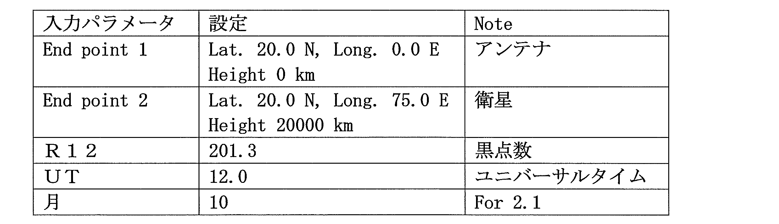
次の表4は、従来のNeQuickプログラムによって計算した電離層遅延量(Origin
al)に対して、本実施形態によって積分演算の分割数の上限が設定されている場合の電離
層遅延量(Reduced)と、双方の電離層遅延量の丸め誤差(Delta)とを示している。

数と、分割数2nによって算出された総電子数との差が、所定の閾値Th未満となった場
合、分割数を2n-1に決定して電離層遅延量の計算を行う。上記表では、最終的に決定
された分割数2n-1によって算出された電離層遅延量は71.037mとなっている。
表4は、条件を太陽活動が活発で、昼間の低仰角衛星を想定しため、かなり大きな電離
層遅延量が発生している。しかし、分割数が8(=23)であっても、本実施形態による電
離層遅延量は、従来のNeQuickにプログラムよる計算に比して、1m以内の誤差し
かない。従って、分割数は“8”として電離層遅延量を求めても十分な測定制度が確保で
きることが分かる。一方、分割数の上限を設けることにより、時間計算量を削減できる。
<2.3.3 演算処理の内容>
図7は、本実施形態による電離層遅延量演算部13b´による演算処理(図2のステッ
プ103)の内容を示すフローチャートである。上述の通り、電離層遅延量の演算には、
受信機1´においてNeQuickプログラムを実行させ、NeQuickモデルに基づ
いて電離層遅延量を演算する。
層遅延量が発生している。しかし、分割数が8(=23)であっても、本実施形態による電
離層遅延量は、従来のNeQuickにプログラムよる計算に比して、1m以内の誤差し
かない。従って、分割数は“8”として電離層遅延量を求めても十分な測定制度が確保で
きることが分かる。一方、分割数の上限を設けることにより、時間計算量を削減できる。
<2.3.3 演算処理の内容>
図7は、本実施形態による電離層遅延量演算部13b´による演算処理(図2のステッ
プ103)の内容を示すフローチャートである。上述の通り、電離層遅延量の演算には、
受信機1´においてNeQuickプログラムを実行させ、NeQuickモデルに基づ
いて電離層遅延量を演算する。
なお、フローチャートにおいて、nは、衛星―アンテナの2点間における総電子数sT
ECを積分演算するに際して、同2点間の分割数2nの指数nである。
ECを積分演算するに際して、同2点間の分割数2nの指数nである。
S2031:n=2とする。ここでは、衛星―アンテナの2点間の分割数の下限を22
としている。なお、この分割数の下限は電離層遅延量演算部13b´により予め設定され
ているものとする。
としている。なお、この分割数の下限は電離層遅延量演算部13b´により予め設定され
ているものとする。
S2032:n<4かどうかを判断する。ここでは、衛星―アンテナの2点間の分割数
の上限を23としている。従って、n<4を満たさなければ、S2036ステップに進ん
で電離層遅延量を決定し、n<4を満たせば、S2033に進んで積分を継続する。
の上限を23としている。従って、n<4を満たさなければ、S2036ステップに進ん
で電離層遅延量を決定し、n<4を満たせば、S2033に進んで積分を継続する。
なお、この分割数の上限は電離層遅延量演算部13b´により予め設定されているもの
とする。
とする。
S2033:分割数2nの場合の、衛星―アンテナの2点間における総電子数sTEC
Nを積分する。
Nを積分する。
S2034:ステップS2033において算出した総電子数sTECNを、メモリに格
納する。なお、sTECNは、衛星―アンテナの2点間の分割数を2nとして場合の総電
子数である。
納する。なお、sTECNは、衛星―アンテナの2点間の分割数を2nとして場合の総電
子数である。
S2035:総電子数sTECNと総電子数sTECN-1(メモリに格納された、分
割数2n-1のときの総電子数)との差分(絶対値)が、所定の閾値Th未満かどうかを
判断する。ここで、所定の閾値Thとは、NeQuickプログラムにおいて予め設定さ
れている閾値であって、分割数に因る電離層遅延量の誤差が無視できる程度に十分に小さ
い値に設定されている(例えば、前の値sTECN-1の1000分の1)。
割数2n-1のときの総電子数)との差分(絶対値)が、所定の閾値Th未満かどうかを
判断する。ここで、所定の閾値Thとは、NeQuickプログラムにおいて予め設定さ
れている閾値であって、分割数に因る電離層遅延量の誤差が無視できる程度に十分に小さ
い値に設定されている(例えば、前の値sTECN-1の1000分の1)。
S2036:ステップS2035において分割数に因る総電子数の誤差が閾値Th未満
であると判断された場合、又はステップS2032において分割数が23を超えたと判断
された場合、総電子数をsTECN-1と決定し、電離層遅延量を演算し(数式1)、結
果を擬似距離補正部13cに出力する。
であると判断された場合、又はステップS2032において分割数が23を超えたと判断
された場合、総電子数をsTECN-1と決定し、電離層遅延量を演算し(数式1)、結
果を擬似距離補正部13cに出力する。
S2037:ステップS2035において分割数に因る総電子数の誤差が閾値Th以上
であると判断された場合、nをインクリメントしてステップS2032に戻る。
であると判断された場合、nをインクリメントしてステップS2032に戻る。
なお、上記電離層遅延部13b´による処理の内容は一例であり、各処理の順序や設定
は上記に限定されるものではない。例えば、分割数2nは上限を23とせず、条件に応じ
て増減させてもよい。また、nの初期値も2に限定されない、例えば、3としてもよい(
つまり、積分値は1回しか求めない)。
<2.4 実施形態2の効果>
上記実施形態においては、NeQuickプログラムを起動させた受信機1´は、測位
演算部13の電離層遅延量演算部13b´により総電子数を積分するとき、衛星-アンテ
ナの2点間の分割数の上限を設けている。これにより、電離層遅延量演算部13b´によ
る電離層遅延量の時間計算量は大幅に削減される。この結果、測位演算部13による測位
演算が速くなり、位置情報を速やかに得ることができる。
<2.5 実施形態2の変形例>
上記説明においては、衛星-アンテナの2点間において総電子数を積分するときの分割
数の上限及び/又は下限は予め設定されていたが、本実施形態はこれに限定されない。
は上記に限定されるものではない。例えば、分割数2nは上限を23とせず、条件に応じ
て増減させてもよい。また、nの初期値も2に限定されない、例えば、3としてもよい(
つまり、積分値は1回しか求めない)。
<2.4 実施形態2の効果>
上記実施形態においては、NeQuickプログラムを起動させた受信機1´は、測位
演算部13の電離層遅延量演算部13b´により総電子数を積分するとき、衛星-アンテ
ナの2点間の分割数の上限を設けている。これにより、電離層遅延量演算部13b´によ
る電離層遅延量の時間計算量は大幅に削減される。この結果、測位演算部13による測位
演算が速くなり、位置情報を速やかに得ることができる。
<2.5 実施形態2の変形例>
上記説明においては、衛星-アンテナの2点間において総電子数を積分するときの分割
数の上限及び/又は下限は予め設定されていたが、本実施形態はこれに限定されない。
分割数の上限及び/又は下限は、電離層遅延量演算時に逐次設定することもできる。
この場合、図4の処理毎に、電離層遅延量演算部13b´が分割数の上限及び/又は下
限を決定する。
限を決定する。
更に、分割数の上限及び/又は下限は、衛星毎、遅延量の絶対値毎、受信位置、測位の
時期、太陽活動、時間等の測位の条件に応じて複数設定されてもよい。また予め複数の分
割数の上限及び/又は下限を格納しておき、同様の条件のときに対応する分割数を選択し
て、電離層遅延量を計算するようにしてもよい。
<2.6 実施形態2の評価>
以下、いくつかの条件の下、本実施形態により電離層遅延量の演算を行った場合の推定
誤差を評価する。
<2.6.1 条件>
次の表5は、設定した条件を示す。テスト1とテスト2は真南に位置する衛星とし、そ
れぞれ高仰角と低仰角の2パターンを設定し、それぞれ昼間と夜間双方の推定誤差を算出
した。また、テスト3とテスト4は東方向に位置する衛星とし、高仰角と低仰角の2パタ
ーンを設定し、同様にそれぞれ昼間と夜間双方の推定誤差を算出した。
時期、太陽活動、時間等の測位の条件に応じて複数設定されてもよい。また予め複数の分
割数の上限及び/又は下限を格納しておき、同様の条件のときに対応する分割数を選択し
て、電離層遅延量を計算するようにしてもよい。
<2.6 実施形態2の評価>
以下、いくつかの条件の下、本実施形態により電離層遅延量の演算を行った場合の推定
誤差を評価する。
<2.6.1 条件>
次の表5は、設定した条件を示す。テスト1とテスト2は真南に位置する衛星とし、そ
れぞれ高仰角と低仰角の2パターンを設定し、それぞれ昼間と夜間双方の推定誤差を算出
した。また、テスト3とテスト4は東方向に位置する衛星とし、高仰角と低仰角の2パタ
ーンを設定し、同様にそれぞれ昼間と夜間双方の推定誤差を算出した。
R12(月毎の太陽黒点数)は1931-2001年の観測値の最小、平均、最大値の
3パターンを設定した。
3パターンを設定した。

表6は、各R12における推定誤差を示す。なお、R12の値によって電離層遅延量の
絶対値が異なると考えられ、推定誤差もR12によって変わる傾向がある。R12を「2
01.3」と設定した場合が最も誤差が大きかったものの,最大で約1m、1シグマで約
0.2mと推定できた。

される電離層遅延量の誤差は、いかなる条件下においても許容範囲内に収まることがわか
る。
<3.実施形態3>
実施形態3においては、GNSS受信機は、上記実施形態1及び2の双方による電離層
遅延量の計算を行う。
<3.1 受信機の構成>
本実施形態に係るGNSS受信機の構成は、実施形態1(図1)と同様である。
<3.2 受信機の動作>
本実施形態に係るGNSS受信機は、次に説明する電離層遅延量の演算処理の内容を除
いては、実施形態1(図2)と同様に動作する。
<3.3 電離層遅延量の演算処理>
本実施形態に係る電離層遅延量の演算処理においては、電離層遅延量演算部13bは、
処理済CCIRファイルを読み出す(実施形態1;図4のステップS1031)と共に、
衛星-アンテナの2点間の総電子数を積分するときの分割数に上限を設定して、電離層遅
延量を演算する(実施形態2;図7のステップS2031~ステップS2037)。
なお、本実施形態においても、上記実施形態1の変形例と同様に、CCIRファイル処
理部13dは、電離層遅延量演算部13bによる電離層遅延量の計算時に逐次CCIRフ
ァイルに対する削減処理を行ってもよい。
<3.4 実施形態3の効果>
上記実施形態においては、NeQuickプログラムを起動させた受信機1は、測位演
算部13の電離層遅延量演算部13bにより総電子数を積分するとき、衛星-アンテナの
2点間の分割数の上限を設けており、更に容量を削減した処理済のCCIRファイルを用
いる。これにより、電離層遅延量演算部13bによる電離層遅延量の時間計算量及び空間
計算量は削減される。
<3.5 実施形態3の評価>
以下、いくつかの条件の下、本実施形態により電離層遅延量の演算を行った場合の推定
誤差を評価する。
<3.5.1 条件>
各条件におけるパラメータは、実施形態2(表5)と同様である。
<3.5.2 推定誤差>
表7は、各R12における推定誤差を示す。なお、R12の値によって電離層遅延量の
絶対値が異なると考えられ、推定誤差もR12によって変わる傾向がある。R12を「2
01.3」を設定した場合が最も誤差が大きかったものの,最大で約7m、1シグマで約
2.1mと推定できた。
理部13dは、電離層遅延量演算部13bによる電離層遅延量の計算時に逐次CCIRフ
ァイルに対する削減処理を行ってもよい。
<3.4 実施形態3の効果>
上記実施形態においては、NeQuickプログラムを起動させた受信機1は、測位演
算部13の電離層遅延量演算部13bにより総電子数を積分するとき、衛星-アンテナの
2点間の分割数の上限を設けており、更に容量を削減した処理済のCCIRファイルを用
いる。これにより、電離層遅延量演算部13bによる電離層遅延量の時間計算量及び空間
計算量は削減される。
<3.5 実施形態3の評価>
以下、いくつかの条件の下、本実施形態により電離層遅延量の演算を行った場合の推定
誤差を評価する。
<3.5.1 条件>
各条件におけるパラメータは、実施形態2(表5)と同様である。
<3.5.2 推定誤差>
表7は、各R12における推定誤差を示す。なお、R12の値によって電離層遅延量の
絶対値が異なると考えられ、推定誤差もR12によって変わる傾向がある。R12を「2
01.3」を設定した場合が最も誤差が大きかったものの,最大で約7m、1シグマで約
2.1mと推定できた。
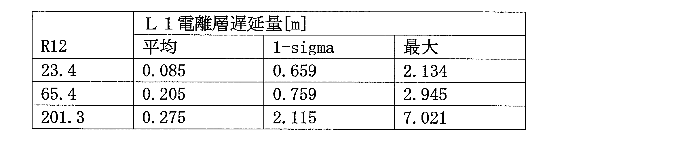
した場合、推定される電離層遅延量の誤差は、実施形態2の時間計算量のみを削減した場
合よりも大きくなるが、許容範囲内に収まることがわかる。
<4 その他実施形態>
本発明の実施形態は、前述の実施形態に限られず、本発明の趣旨を逸脱しない範囲で種
々の修正、変更及び組み合わせが可能である。また、前述の実施形態は、本質的に好まし
い例示であって、本発明、その適用物、あるいはその用途の範囲を制限することを意図す
るものではない。
例えば、上記実施形態においては、測位演算部13やデータ処理部12は集積回路とし
て説明したが、本発明は、プロセッサやメモリを用いた測位方法やコンピュータプログラ
ムとしても実施し得るものである。また、本発明は、上記集積回路を備えた情報端末機器
(移動端末機器を含む)としても実施し得るものである。
て説明したが、本発明は、プロセッサやメモリを用いた測位方法やコンピュータプログラ
ムとしても実施し得るものである。また、本発明は、上記集積回路を備えた情報端末機器
(移動端末機器を含む)としても実施し得るものである。
1 GNSS受信機
2 アンテナ
5 衛星
11 L1受信部
12 データ処理部
13 測位演算部(測位装置)
13a 擬似距離測定部
13b 電離層遅延量演算部
13c 擬似距離補正部
13d CCIRファイル処理部
14 出力部
15 入力部
16 メモリ
1´ GNSS受信機
13b´ 電離層遅延量演算部
2 アンテナ
5 衛星
11 L1受信部
12 データ処理部
13 測位演算部(測位装置)
13a 擬似距離測定部
13b 電離層遅延量演算部
13c 擬似距離補正部
13d CCIRファイル処理部
14 出力部
15 入力部
16 メモリ
1´ GNSS受信機
13b´ 電離層遅延量演算部
Claims (8)
- 測位用衛星からGNSS受信機のアンテナにより受信した信号に基づき測位を行う測位
装置であって、
前記測位用衛星と前記アンテナ間の擬似距離を測定する擬似距離測定部と、
前記擬似距離に含まれる電離層遅延量を演算する電離層遅延量演算部と、
前記電離層遅延量に基づき前記擬似距離を補正することにより測位演算を行う擬似距離
補正部と、
異なる月にそれぞれ対応する複数のCCIRファイルを所定の条件に応じてまとめた処
理済CCIRファイルを記憶する処理済CCIRファイル記憶部と、
を備え、
前記電離層遅延量演算部は、前記処理済CCIRファイルに基づき前記電離層遅延量を
演算する、
測位装置。 - 異なる月にそれぞれ対応する複数のCCIRファイルを所定の条件に応じてまとめるこ
とにより前記処理済CCIRファイルを作成するCCIRファイル処理部を更に備え、
前記CCIRファイル処理部は更に、前記複数のCCIRファイルのビット数を削減す
ることにより前記処理済CCIRファイルを作成する、
請求項1に記載の測位装置。 - 異なる月にそれぞれ対応する複数のCCIRファイルを所定の条件に応じてまとめるこ
とにより前記処理済CCIRファイルを作成するCCIRファイル処理部を更に備え、
前記CCIRファイル処理部は、前記複数のCCIRファイルのうち、値の差が所定値
以下の異なるCCIRファイルをまとめることにより前記処理済ファイルを作成する、
請求項1に記載の測位装置。 - 異なる月にそれぞれ対応する複数のCCIRファイルを所定の条件に応じてまとめるこ
とにより前記処理済CCIRファイルを作成するCCIRファイル処理部を更に備え、
前記CCIRファイル処理部は、前記電離層遅延量演算部が前記電離層遅延量の演算を
行う毎に、前記処理済CCIRファイルを作成する、
請求項1に記載の測位装置。 - 請求項1から4のいずれかに記載の測位装置と、
前記測位用衛星からの信号を受信するアンテナと、
を備える、GNSS受信機。 - 請求項5に記載のGNSS受信機、
を備える、情報端末機器。 - 測位用衛星からGNSS受信機のアンテナにより受信した信号に基づき測位を行う測位
方法であって、
前記測位用衛星と前記アンテナ間の擬似距離を測定する擬似距離測定ステップと、
前記擬似距離に含まれる電離層遅延量を演算する電離層遅延量演算ステップと、
前記電離層遅延量に基づき前記擬似距離を補正することにより測位演算を行う擬似距離
ステップと、
異なる月にそれぞれ対応する複数のCCIRファイルを所定の条件に応じてまとめるこ
とにより処理済CCIRファイルを作成するCCIRファイル処理ステップと、
を備え、
前記電離層遅延量演算ステップにおいては、前記処理済CCIRファイルに基づき前記
電離層遅延量を演算する、
測位方法。 - 測位用衛星からGNSS受信機のアンテナにより受信した信号に基づき測位を行う測位
方法をコンピュータに実行させるプログラムであって、前記方法は、
前記測位用衛星と前記アンテナ間の擬似距離を測定する擬似距離測定ステップと、
前記擬似距離に含まれる電離層遅延量を演算する電離層遅延量演算ステップと、
前記電離層遅延量に基づき前記擬似距離を補正することにより測位演算を行う擬似距離
ステップと、
異なる月にそれぞれ対応する複数のCCIRファイルを所定の条件に応じてまとめるこ
とにより処理済CCIRファイルを作成するCCIRファイル処理ステップと、
を備え、
前記電離層遅延量演算ステップにおいては、前記処理済CCIRファイルに基づき前記
電離層遅延量を演算する、
プログラム。
Applications Claiming Priority (2)
| Application Number | Priority Date | Filing Date | Title |
|---|---|---|---|
| JP2011063879 | 2011-03-23 | ||
| JP2011-063879 | 2011-03-23 |
Publications (1)
| Publication Number | Publication Date |
|---|---|
| WO2012128125A1 true WO2012128125A1 (ja) | 2012-09-27 |
Family
ID=46879277
Family Applications (1)
| Application Number | Title | Priority Date | Filing Date |
|---|---|---|---|
| PCT/JP2012/056431 Ceased WO2012128125A1 (ja) | 2011-03-23 | 2012-03-13 | 測位装置、gnss受信機、情報端末機器、測位方法及びプログラム |
Country Status (1)
| Country | Link |
|---|---|
| WO (1) | WO2012128125A1 (ja) |
Cited By (3)
| Publication number | Priority date | Publication date | Assignee | Title |
|---|---|---|---|---|
| JP2017026632A (ja) * | 2014-10-30 | 2017-02-02 | 三菱電機株式会社 | 情報処理装置 |
| US10598792B2 (en) | 2014-12-02 | 2020-03-24 | Mitsubishi Electric Corporation | Information processing device and positioning device |
| CN113671534A (zh) * | 2020-05-15 | 2021-11-19 | 华为技术有限公司 | 一种定位补偿方法、车载单元、介质及系统 |
-
2012
- 2012-03-13 WO PCT/JP2012/056431 patent/WO2012128125A1/ja not_active Ceased
Non-Patent Citations (1)
| Title |
|---|
| BENOIT BIDAINE: "Ionosphere Crossing of GALILEO Signals", UNIVERSITY OF LIEGE, 26 June 2006 (2006-06-26) * |
Cited By (6)
| Publication number | Priority date | Publication date | Assignee | Title |
|---|---|---|---|---|
| JP2017026632A (ja) * | 2014-10-30 | 2017-02-02 | 三菱電機株式会社 | 情報処理装置 |
| US10802152B2 (en) | 2014-10-30 | 2020-10-13 | Mitsubishi Electric Corporation | Positioning device |
| US10816669B2 (en) | 2014-10-30 | 2020-10-27 | Mitsubishi Electric Corporation | Information processing device |
| US10598792B2 (en) | 2014-12-02 | 2020-03-24 | Mitsubishi Electric Corporation | Information processing device and positioning device |
| CN113671534A (zh) * | 2020-05-15 | 2021-11-19 | 华为技术有限公司 | 一种定位补偿方法、车载单元、介质及系统 |
| CN113671534B (zh) * | 2020-05-15 | 2025-02-18 | 华为技术有限公司 | 一种定位补偿方法、车载单元、介质及系统 |
Similar Documents
| Publication | Publication Date | Title |
|---|---|---|
| JP5706517B2 (ja) | 測位装置、gnss受信機、情報端末機器、測位方法及びプログラム | |
| CN110568459B (zh) | 基于igs和cors站的区域电离层tec实时监测方法 | |
| JP5352422B2 (ja) | 測位装置及びプログラム | |
| JP6345315B2 (ja) | 測位装置 | |
| CN104101888B (zh) | 一种适合于中国区域的gnss电离层延迟精确建模方法 | |
| JP6279078B2 (ja) | 変換装置及びプログラム | |
| CN105929424A (zh) | 一种bds/gps高精度定位方法 | |
| CN107765275A (zh) | 广域差分定位方法、装置、终端及计算机可读存储介质 | |
| KR101783552B1 (ko) | 다중 위성 항법 시스템을 이용하는 단독 전리층 지연 오차 보정 장치 및 방법 | |
| US11221415B2 (en) | Positioning device and positioning method | |
| CN109313272A (zh) | 使用速度积分的改进gnss接收器 | |
| WO2020135543A1 (zh) | 一种高精度的卫星定位方法、定位终端和定位系统 | |
| CN115629410A (zh) | 一种城市复杂环境中的沿街方向定位方法、系统及产品 | |
| CN115327593A (zh) | 基于无人机的定位方法、系统及存储介质 | |
| WO2012128125A1 (ja) | 測位装置、gnss受信機、情報端末機器、測位方法及びプログラム | |
| JP2010145178A (ja) | 移動体位置特定装置 | |
| KR100305714B1 (ko) | 지역적 전리층 지연 모델의 모델링방법 및 이를 이용한 보정위성 항법 시스템의 위치 보정방법 | |
| CN117949988A (zh) | 定位方法、装置、计算机可读介质及电子设备 | |
| CN118604862B (zh) | 一种提高gnss定位精度的方法、系统及定位终端 | |
| CN116263334B (zh) | 定位方法、装置、计算机设备、存储介质和程序产品 | |
| CN118688832A (zh) | 一种导航系统中数据差分后处理的精度监测方法及系统 | |
| CN121613485A (zh) | 基于无人机的定位方法、装置、设备及存储介质 | |
| CN121634155A (zh) | 一种周跳处理方法、装置、设备及介质 | |
| CN120779437A (zh) | 一种基于双频卫星信号的定位方法及相关设备 | |
| HK40038747A (en) | Method and apparatus for evaluating terminal positioning accuracy, device, and medium |
Legal Events
| Date | Code | Title | Description |
|---|---|---|---|
| 121 | Ep: the epo has been informed by wipo that ep was designated in this application |
Ref document number: 12761168 Country of ref document: EP Kind code of ref document: A1 |
|
| NENP | Non-entry into the national phase |
Ref country code: DE |
|
| 122 | Ep: pct application non-entry in european phase |
Ref document number: 12761168 Country of ref document: EP Kind code of ref document: A1 |
|
| NENP | Non-entry into the national phase |
Ref country code: JP |