WO2012128103A1 - Seal structure for slewing bearing, and slewing bearing - Google Patents
Seal structure for slewing bearing, and slewing bearing Download PDFInfo
- Publication number
- WO2012128103A1 WO2012128103A1 PCT/JP2012/056278 JP2012056278W WO2012128103A1 WO 2012128103 A1 WO2012128103 A1 WO 2012128103A1 JP 2012056278 W JP2012056278 W JP 2012056278W WO 2012128103 A1 WO2012128103 A1 WO 2012128103A1
- Authority
- WO
- WIPO (PCT)
- Prior art keywords
- seal
- base
- lip
- groove
- slewing bearing
- Prior art date
Links
Images


Classifications
-
- F—MECHANICAL ENGINEERING; LIGHTING; HEATING; WEAPONS; BLASTING
- F16—ENGINEERING ELEMENTS AND UNITS; GENERAL MEASURES FOR PRODUCING AND MAINTAINING EFFECTIVE FUNCTIONING OF MACHINES OR INSTALLATIONS; THERMAL INSULATION IN GENERAL
- F16J—PISTONS; CYLINDERS; SEALINGS
- F16J15/00—Sealings
- F16J15/16—Sealings between relatively-moving surfaces
- F16J15/32—Sealings between relatively-moving surfaces with elastic sealings, e.g. O-rings
- F16J15/3268—Mounting of sealing rings
- F16J15/3276—Mounting of sealing rings with additional static sealing between the sealing, or its casing or support, and the surface on which it is mounted
-
- F—MECHANICAL ENGINEERING; LIGHTING; HEATING; WEAPONS; BLASTING
- F16—ENGINEERING ELEMENTS AND UNITS; GENERAL MEASURES FOR PRODUCING AND MAINTAINING EFFECTIVE FUNCTIONING OF MACHINES OR INSTALLATIONS; THERMAL INSULATION IN GENERAL
- F16C—SHAFTS; FLEXIBLE SHAFTS; ELEMENTS OR CRANKSHAFT MECHANISMS; ROTARY BODIES OTHER THAN GEARING ELEMENTS; BEARINGS
- F16C33/00—Parts of bearings; Special methods for making bearings or parts thereof
- F16C33/72—Sealings
- F16C33/76—Sealings of ball or roller bearings
- F16C33/78—Sealings of ball or roller bearings with a diaphragm, disc, or ring, with or without resilient members
- F16C33/7816—Details of the sealing or parts thereof, e.g. geometry, material
- F16C33/782—Details of the sealing or parts thereof, e.g. geometry, material of the sealing region
- F16C33/7823—Details of the sealing or parts thereof, e.g. geometry, material of the sealing region of sealing lips
-
- F—MECHANICAL ENGINEERING; LIGHTING; HEATING; WEAPONS; BLASTING
- F16—ENGINEERING ELEMENTS AND UNITS; GENERAL MEASURES FOR PRODUCING AND MAINTAINING EFFECTIVE FUNCTIONING OF MACHINES OR INSTALLATIONS; THERMAL INSULATION IN GENERAL
- F16C—SHAFTS; FLEXIBLE SHAFTS; ELEMENTS OR CRANKSHAFT MECHANISMS; ROTARY BODIES OTHER THAN GEARING ELEMENTS; BEARINGS
- F16C33/00—Parts of bearings; Special methods for making bearings or parts thereof
- F16C33/72—Sealings
- F16C33/76—Sealings of ball or roller bearings
- F16C33/78—Sealings of ball or roller bearings with a diaphragm, disc, or ring, with or without resilient members
- F16C33/7816—Details of the sealing or parts thereof, e.g. geometry, material
- F16C33/783—Details of the sealing or parts thereof, e.g. geometry, material of the mounting region
-
- F—MECHANICAL ENGINEERING; LIGHTING; HEATING; WEAPONS; BLASTING
- F16—ENGINEERING ELEMENTS AND UNITS; GENERAL MEASURES FOR PRODUCING AND MAINTAINING EFFECTIVE FUNCTIONING OF MACHINES OR INSTALLATIONS; THERMAL INSULATION IN GENERAL
- F16C—SHAFTS; FLEXIBLE SHAFTS; ELEMENTS OR CRANKSHAFT MECHANISMS; ROTARY BODIES OTHER THAN GEARING ELEMENTS; BEARINGS
- F16C33/00—Parts of bearings; Special methods for making bearings or parts thereof
- F16C33/72—Sealings
- F16C33/76—Sealings of ball or roller bearings
- F16C33/78—Sealings of ball or roller bearings with a diaphragm, disc, or ring, with or without resilient members
- F16C33/7889—Sealings of ball or roller bearings with a diaphragm, disc, or ring, with or without resilient members mounted to an inner race and extending toward the outer race
-
- F—MECHANICAL ENGINEERING; LIGHTING; HEATING; WEAPONS; BLASTING
- F16—ENGINEERING ELEMENTS AND UNITS; GENERAL MEASURES FOR PRODUCING AND MAINTAINING EFFECTIVE FUNCTIONING OF MACHINES OR INSTALLATIONS; THERMAL INSULATION IN GENERAL
- F16J—PISTONS; CYLINDERS; SEALINGS
- F16J15/00—Sealings
- F16J15/16—Sealings between relatively-moving surfaces
- F16J15/32—Sealings between relatively-moving surfaces with elastic sealings, e.g. O-rings
- F16J15/3204—Sealings between relatively-moving surfaces with elastic sealings, e.g. O-rings with at least one lip
- F16J15/3232—Sealings between relatively-moving surfaces with elastic sealings, e.g. O-rings with at least one lip having two or more lips
- F16J15/3236—Sealings between relatively-moving surfaces with elastic sealings, e.g. O-rings with at least one lip having two or more lips with at least one lip for each surface, e.g. U-cup packings
-
- F—MECHANICAL ENGINEERING; LIGHTING; HEATING; WEAPONS; BLASTING
- F16—ENGINEERING ELEMENTS AND UNITS; GENERAL MEASURES FOR PRODUCING AND MAINTAINING EFFECTIVE FUNCTIONING OF MACHINES OR INSTALLATIONS; THERMAL INSULATION IN GENERAL
- F16J—PISTONS; CYLINDERS; SEALINGS
- F16J15/00—Sealings
- F16J15/16—Sealings between relatively-moving surfaces
- F16J15/34—Sealings between relatively-moving surfaces with slip-ring pressed against a more or less radial face on one member
- F16J15/3436—Pressing means
- F16J15/3456—Pressing means without external means for pressing the ring against the face, e.g. slip-ring with a resilient lip
-
- F—MECHANICAL ENGINEERING; LIGHTING; HEATING; WEAPONS; BLASTING
- F05—INDEXING SCHEMES RELATING TO ENGINES OR PUMPS IN VARIOUS SUBCLASSES OF CLASSES F01-F04
- F05B—INDEXING SCHEME RELATING TO WIND, SPRING, WEIGHT, INERTIA OR LIKE MOTORS, TO MACHINES OR ENGINES FOR LIQUIDS COVERED BY SUBCLASSES F03B, F03D AND F03G
- F05B2240/00—Components
- F05B2240/50—Bearings
-
- F—MECHANICAL ENGINEERING; LIGHTING; HEATING; WEAPONS; BLASTING
- F05—INDEXING SCHEMES RELATING TO ENGINES OR PUMPS IN VARIOUS SUBCLASSES OF CLASSES F01-F04
- F05B—INDEXING SCHEME RELATING TO WIND, SPRING, WEIGHT, INERTIA OR LIKE MOTORS, TO MACHINES OR ENGINES FOR LIQUIDS COVERED BY SUBCLASSES F03B, F03D AND F03G
- F05B2240/00—Components
- F05B2240/57—Seals
-
- F—MECHANICAL ENGINEERING; LIGHTING; HEATING; WEAPONS; BLASTING
- F05—INDEXING SCHEMES RELATING TO ENGINES OR PUMPS IN VARIOUS SUBCLASSES OF CLASSES F01-F04
- F05B—INDEXING SCHEME RELATING TO WIND, SPRING, WEIGHT, INERTIA OR LIKE MOTORS, TO MACHINES OR ENGINES FOR LIQUIDS COVERED BY SUBCLASSES F03B, F03D AND F03G
- F05B2260/00—Function
- F05B2260/60—Fluid transfer
- F05B2260/63—Preventing clogging or obstruction of flow paths by dirt, dust, or foreign particles
-
- F—MECHANICAL ENGINEERING; LIGHTING; HEATING; WEAPONS; BLASTING
- F16—ENGINEERING ELEMENTS AND UNITS; GENERAL MEASURES FOR PRODUCING AND MAINTAINING EFFECTIVE FUNCTIONING OF MACHINES OR INSTALLATIONS; THERMAL INSULATION IN GENERAL
- F16C—SHAFTS; FLEXIBLE SHAFTS; ELEMENTS OR CRANKSHAFT MECHANISMS; ROTARY BODIES OTHER THAN GEARING ELEMENTS; BEARINGS
- F16C19/00—Bearings with rolling contact, for exclusively rotary movement
- F16C19/02—Bearings with rolling contact, for exclusively rotary movement with bearing balls essentially of the same size in one or more circular rows
- F16C19/14—Bearings with rolling contact, for exclusively rotary movement with bearing balls essentially of the same size in one or more circular rows for both radial and axial load
- F16C19/16—Bearings with rolling contact, for exclusively rotary movement with bearing balls essentially of the same size in one or more circular rows for both radial and axial load with a single row of balls
-
- F—MECHANICAL ENGINEERING; LIGHTING; HEATING; WEAPONS; BLASTING
- F16—ENGINEERING ELEMENTS AND UNITS; GENERAL MEASURES FOR PRODUCING AND MAINTAINING EFFECTIVE FUNCTIONING OF MACHINES OR INSTALLATIONS; THERMAL INSULATION IN GENERAL
- F16C—SHAFTS; FLEXIBLE SHAFTS; ELEMENTS OR CRANKSHAFT MECHANISMS; ROTARY BODIES OTHER THAN GEARING ELEMENTS; BEARINGS
- F16C2300/00—Application independent of particular apparatuses
- F16C2300/10—Application independent of particular apparatuses related to size
- F16C2300/14—Large applications, e.g. bearings having an inner diameter exceeding 500 mm
-
- F—MECHANICAL ENGINEERING; LIGHTING; HEATING; WEAPONS; BLASTING
- F16—ENGINEERING ELEMENTS AND UNITS; GENERAL MEASURES FOR PRODUCING AND MAINTAINING EFFECTIVE FUNCTIONING OF MACHINES OR INSTALLATIONS; THERMAL INSULATION IN GENERAL
- F16C—SHAFTS; FLEXIBLE SHAFTS; ELEMENTS OR CRANKSHAFT MECHANISMS; ROTARY BODIES OTHER THAN GEARING ELEMENTS; BEARINGS
- F16C2360/00—Engines or pumps
- F16C2360/31—Wind motors
-
- F—MECHANICAL ENGINEERING; LIGHTING; HEATING; WEAPONS; BLASTING
- F16—ENGINEERING ELEMENTS AND UNITS; GENERAL MEASURES FOR PRODUCING AND MAINTAINING EFFECTIVE FUNCTIONING OF MACHINES OR INSTALLATIONS; THERMAL INSULATION IN GENERAL
- F16C—SHAFTS; FLEXIBLE SHAFTS; ELEMENTS OR CRANKSHAFT MECHANISMS; ROTARY BODIES OTHER THAN GEARING ELEMENTS; BEARINGS
- F16C33/00—Parts of bearings; Special methods for making bearings or parts thereof
- F16C33/30—Parts of ball or roller bearings
- F16C33/58—Raceways; Race rings
- F16C33/583—Details of specific parts of races
Definitions
- the present invention is, for example, a swivel used for a swivel part of various machines used in the vicinity of the outdoors or indoors, such as a swivel seat for a yaw and a blade of a wind power generator, a deck crane, a construction machine, and a lifting machine.
- the present invention relates to a seal structure of a bearing and a slewing bearing.
- Slewing bearings used for wind power generation devices such as yaw and swivel seats for blades are generally lubricated with grease.
- This slewing bearing is provided with a rubber seal in order to prevent foreign matters from entering from outside or grease leakage from inside the bearing (Patent Documents 1 and 2).
- Nitrile, chloroprene, acrylic, etc. are used as the material of this rubber.
- rubber seals used for slewing bearings for yaw and blades of wind power generators have an important function of preventing grease leakage from the viewpoint of protecting the surrounding environment. Since the slewing bearing is generally operated at a low speed, there is little problem of heat generation. However, as shown in FIG. 14, when additional grease is supplied from the greasing pipe 50, the pressure inside the bearing having the shaft center C is increased. Rises. As shown in the figure, the grease supply pipe 50 is a pipe that penetrates radially from the outer ring outer diameter surface 51 or the inner ring inner diameter surface 52 toward the bearing interior. As described above, since the pressure inside the bearing rises, the internal pressure acts on the rubber seal portion 53.
- the direction of the seal lip 55 is two patterns: an inward lip 55a extending inwardly in the axial direction of the bearing space as it goes toward the tip, and an outward lip 55b extending inclining outward in the axial direction of the bearing space as it goes toward the tip. is there.
- an inward lip 55a is required.
- the inward lip 55a is applied with pressure higher than expected, there is a problem that the lip is reversed.
- the sealing torque increases, which may affect the specifications of the drive device, that is, it may be necessary to increase the capacity of the turning torque.
- An object of the present invention is to provide a seal structure for a slewing bearing and a slewing bearing that can prevent the lip portion of the seal member from being reversed and the seal member from falling off when the internal pressure is increased, and can reduce the seal torque. .
- a raceway groove is formed in each of the race rings of the inner ring and the outer ring, a plurality of rolling elements are provided between the race grooves of the inner and outer rings, and at the axial ends of the inner and outer rings, A step that is uneven in the axial direction is provided between the inner and outer rings, and an elastic seal member that seals the axial end of the inner and outer rings having the step is provided.
- the seal member includes a base fixed to a portion protruding from the concave raceway of the convex raceway that is the convex side of the step, and one or more that are in contact with the concave raceway that is the concave side of the step.
- One of the lip portions includes a main lip extending obliquely so as to be positioned on the inner side in the axial direction of the bearing space toward the tip, and on the bearing space side of the concave bearing ring.
- a seal slidable contact surface portion that slidably contacts the main lip of the seal member, and an annular protruding portion that protrudes in the radial direction is provided on the end side of the peripheral surface of the concave raceway.
- a seal sliding side inclined portion that is inclined so as to be positioned on the outer side in the axial direction toward the protruding tip.
- An annular groove is provided on the peripheral surface of the convex raceway, and a fixing groove is provided on an outer surface in the axial direction at the bottom of the annular groove, and the base portion of the seal member includes the peripheral surface of the convex raceway and the circumferential surface.
- a seal fixing side inclined portion that is inclined so as to be positioned on the side is provided.
- the main lip when internal pressure is applied to the seal member, the main lip is pressed against the seal sliding side inclined portion of the annular projection of the concave raceway, and the base is inclined to the seal fixing side of the convex raceway. Pressed against the part. That is, the main lip and the base of the seal member are both supported by the race ring.
- the main lip and the base portion come into contact with the respective inclined portions facing each other, the inversion of the lip portion can be suppressed, and the seal member can be prevented from falling off the raceway. Accordingly, in order to prevent the lip portion from being reversed, it is not necessary to increase the lip rigidity by increasing the thickness of the lip portion. Therefore, the thickness of the lip portion can be made thinner than that of the conventional one, and the sealing torque can be reduced.
- the inner surface of the base portion facing the bottom of the annular groove of the convex raceway ring may be connected by a single curved surface or a continuous curved surface having no inflection point.
- the inner surface of the base portion facing the bottom portion of the annular groove of the convex raceway ring may be connected to a plurality of surfaces having intersection angles of 90 degrees or more and 180 degrees or less.
- the “intersection angle” refers to an angle viewed from the inside of the seal member. In these cases, the rigidity of the base portion of the seal member can be increased and local deformation can be prevented.
- the angle of the intersection line connecting the axial inner side surface of the main lip and the base inner side surface of the base may be 180 degrees or more and 270 degrees or less.
- the “angle” refers to an angle viewed from the inside of the seal member.
- the main lip can be positively elastically deformed by applying an internal pressure to a portion connecting the axial inner side surface of the main lip and the base inner side surface of the base portion. Thereby, even if it is a case where the hooking amount of a base is small with respect to an annular wall part, it can prevent that the sealing member is pulled out by the base side.
- the seal slide is formed so that the surface of the annular protrusion extending from the seal sliding side inclined portion toward the convex raceway and the surface of the fixing groove extending from the seal fixing side inclined portion toward the concave raceway are crossed.
- a moving side inclined portion and a seal fixing side inclined portion may be provided.
- the surface where the seal sliding side inclined portion is extended to the convex bearing ring side and the surface where the seal fixing side inclined portion of the fixing groove is extended to the concave bearing ring side are brought close to one plane so that the sealing member When the internal pressure is applied, the main lip and the base of the seal member can be more reliably brought into contact with the surface.
- the main lip may be thinner than the base.
- the seal torque of the lip portion can be reduced, and the main lip can be positively elastically deformed when an internal pressure is applied to the seal member.
- the main lip is surely pressed against the seal sliding side inclined portion of the annular projection of the concave raceway, so that the sealing member can be used even when the hooking amount of the base portion is small relative to the annular wall portion. Can be prevented from coming out on the base side.
- the bottom surface of the fitting groove of the seal base or the side surface of the groove on the bearing space side may be brought into contact with the seal base.
- the coefficient of friction is increased, the fixation of the seal base can be stabilized, and the suppression of grease leakage from the fixed part can be enhanced. Further, since the tightness of the seal lip can be maintained, the sealing performance can be stabilized.
- the sealing member may be made of nitrile or chloroprene.
- the seal member may include, as one of the lip portions, a sub lip branched from the base portion separately from the main lip and in contact with the end surface of the concave raceway. By this sub lip, the sealing performance of the sealing member is further maintained, and grease leakage from the bearing space can be prevented.
- the initial tightening allowance of the main lip may be 2 mm or more and 6 mm or less. By setting such an initial tightening allowance, it is possible to reduce the seal torque and prevent grease leakage from the bearing space.
- the slewing bearing of the present invention is one to which any of the above-mentioned seal structures is applied.
- a wind turbine blade may be supported so as to be rotatable about an axis substantially perpendicular to the main shaft axis with respect to the main shaft.
- the nacelle of the windmill may be supported so as to be rotatable with respect to the support base.
- This slewing bearing is, for example, a bearing that supports the blade of a wind turbine for wind power generation so that it can pivot about an axis substantially perpendicular to the main shaft axis or a nacelle of the wind turbine relative to a support base. Used as a bearing to support.
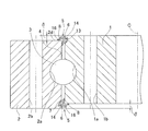
- the slewing bearing is adjacent to the inner ring 1, the outer ring 2, and a plurality of balls 3 that are rotatably interposed between the raceway grooves 1 a and 2 a of the inner and outer rings 1 and 2.
- a spacer (not shown) interposed between the balls 3 and 3 and a seal member 5 described later are provided.
- Each of the raceway grooves 1a and 2a of the inner and outer rings 1 and 2 is composed of two curved surfaces.
- the two curved surfaces constituting each raceway groove 1a, 2a are Gothic arch-shaped arcs having a larger radius of curvature than the balls 3 as rolling elements and different curvature centers.
- Each ball 3 is in contact with the curved surfaces of the inner ring raceway groove 1a and the outer ring raceway groove 2a at a point of contact with each other at four points.
- This slewing bearing is configured as a four-point contact ball bearing.
- the spacer is made of, for example, a resin material, and the spacer has a concave shape in which the ball contact surfaces on both sides form a spherical surface that is deeply recessed toward the center.
- the outer ring 2 is provided with a plurality of through holes 2b at regular intervals in the circumferential direction. These through holes 2b are used, for example, for connecting and fixing the outer ring 2 to a support base 22 (FIGS. 7 and 8) described later.
- the inner ring 1 is also provided with a plurality of through holes 1b at regular intervals in the circumferential direction, and these through holes 1b are used for connecting and fixing the inner ring 1 to, for example, a casing 24 (FIGS. 7 and 8) of a nacelle 23 described later. Used for.
- Each through-hole 1b, 2b is formed in parallel with the bearing axial direction.
- steps ⁇ that are uneven in the axial direction between the inner and outer rings 1 and 2 are provided at the axial ends of the inner and outer rings 1 and 2, in this example, at both ends in the axial direction.
- the bearing space 4 of the inner and outer rings 1 and 2 is filled with grease, and the seal members 5 and 5 seal both axial ends of the inner and outer rings 1 and 2 having the step ⁇ .
- the seal member 5 at one end in the axial direction (upper part in FIG. 1) will be described.
- the convex raceway that is the convex side of the step ⁇ is the inner ring 1
- the concave raceway that is the concave side of the step ⁇ is the outer ring 2.
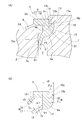
- the seal member 5 is made of an elastic body such as nitrile or chloroprene, and has a base portion 6 and a lip portion 9 including a main lip 7 and a sub lip 8 as shown in FIG.
- the base portion 6 and the lip portion 9 are provided integrally.
- the base portion 6 includes a seal fixing portion 10 that is fixed to the inner ring 1 that is a convex raceway ring, and a seal body portion 11 that is connected to the seal fixing portion 10.
- a fitting groove 10 a is provided on the inner peripheral surface side of the seal fixing portion 10 of the base portion 6.
- the fitting groove 10a is formed so as to open annularly outward in the axial direction.
- the seal fixing portion 10 of the base portion 6 is fixed to a portion of the inner ring 1 that protrudes in the axial direction from the outer ring 2.
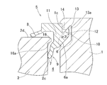
- An annular groove 12 is provided on the outer peripheral surface of the inner ring 1, and a fixed groove 13 recessed in a V shape toward the axially outer side (side away from the bearing space 4) on the axially outer surface at the bottom of the annular groove 12. Is provided.
- a seal fixed side inclined portion 13 a that is inclined so as to be positioned outward in the axial direction toward the groove bottom side portion.
- the largest radial clearance between the tip portion 10b of the seal fixing portion 10 and the engaging portion 10c. ⁇ a is formed to be narrower than when the seal fixing portion 10 is fixed to the inner ring 1 (FIG. 2A).
- the tip portion 10b of the seal fixing portion 10 is elastically deformed radially inward (in other words, the seal fixing part 10 is in contact with the seal fixing side inclined part 13a (separated from the engaging part 10c).
- the engaging portion 10 c of the seal fixing portion 10 is engaged with the step portion 1 c of the inner ring 1.
- the inner side surface 15 on the inner side in the axial direction at the bottom of the annular groove 12 is formed, for example, in parallel with the inclined surface of the seal fixing side inclined portion 13a, and the base portion 6 of the seal member 5 does not interfere with the inner side surface 15 and the groove bottom surface. It is provided as follows. Of the base 6 of the seal member 5, the base inner side surface 6 a facing the bottom of the annular groove 12 is formed as a shape connected with a single curved surface or a continuous curved surface having no inflection point, forming a curved surface inward in the radial direction. Yes.
- the main lip 7 of the lip portion 9 extends in an inclined manner so as to be located on the inner side in the axial direction of the bearing space toward the tip.
- the main lip 7 extends obliquely inward in the axial direction from the outer surface of the seal body 11 facing the inner peripheral surface of the outer ring of the seal body 11.
- the thickness t1 of the main lip 7 is provided to be thinner than the maximum radial thickness t2 of the seal body 11 of the base 6.
- the angle ⁇ 1 of the line connecting the base inner surface 6a facing the bottom of the annular groove 12 and the axial inner surface 7a of the main lip 7 is 180 degrees or more and 270 degrees or less. .
- the base inner side surface 6a is connected by a single curved surface or a continuous curved surface having no inflection point, the tangent line La passing through the axial inner side surface of the main lip 7 of the base inner side surface 6a
- the angle ⁇ 1 of the intersection line connecting the axially inner side surfaces of the main lip 7 is set as described above.
- the “angle” refers to an angle viewed from the inside of the seal member 5.
- the initial fastening allowance of the main lip 7 (the amount of change in the radial position of the tip of the main lip 7 before and after assembling into the bearing) is set to 2 mm or more and 6 mm or less.
- a seal sliding contact surface portion 2c for slidingly contacting the main lip 7 is provided on the inner peripheral surface of the outer ring 2 on the bearing space side of the outer ring 2 that is a concave raceway.
- An annular projecting portion 16 projecting in the radial direction is provided on the inner peripheral surface of the outer ring on the end side of the seal sliding contact surface portion 2c.
- a seal sliding side inclined portion 16a that is inclined so as to be positioned on the outer side in the axial direction toward the protruding tip is provided on the inner surface in the axial direction facing the bearing space in the annular protruding portion 16.
- seal sliding side slope 16 so that the surface S2 extending the seal sliding side inclined portion 16a to the inner ring 1 side and the surface S1 extending the seal fixing side inclined portion 13a of the fixing groove 13 to the outer ring 2 side intersect.
- a portion 16a and a seal fixing side inclined portion 13a are provided.
- the auxiliary lip 8 of the lip portion 9 branches from the seal body portion 11 of the base portion 6 separately from the main lip 7 and contacts the end surface 2d of the outer ring 2. That is, the sub lip 8 extends in an axially inclining manner from the lower end surface portion of the seal body portion 11 facing the end surface 2d of the outer ring 2, and makes axial contact with the end surface 2d of the outer ring 2. As shown in FIG. 2B, the thickness t3 of the sub lip 8 is provided thinner than the thickness t4 of the seal body 11 in the axial direction.
- the secondary lip 8 is also called a dust lip.
- the convex raceway ring that is the convex side of the step ⁇ is the outer ring 2
- the concave side of the step ⁇ is the inner ring 1. Since the seal structure provided at the other end in the axial direction is the same as the seal structure at one end in the axial direction, the same reference numerals as those assigned to the seal structure are attached and the description thereof is omitted.
- the main lip 7 is pressed against the seal sliding side inclined portion 16a of the annular protrusion 16 of the concave raceway, and the base portion 6 is pressed against the seal fixing side inclined portion 13a of the convex raceway. That is, the main lip 7 and the base 6 of the seal member 5 are both supported by the raceway ring. At this time, the main lip 7 and the base portion 6 come into contact with the respective inclined portions 16a and 13a facing each other, so that the inversion of the lip portion 9 can be suppressed and the seal member 5 is prevented from falling off the raceway. can do. Accordingly, in order to prevent the lip portion from being reversed, it is not necessary to increase the lip rigidity by increasing the thickness of the lip portion. Therefore, the thickness of the lip portion 9 can be made thinner than that of the conventional one, and the sealing torque can be reduced.
- the seal member 5 by inserting the base portion 6 of the seal member 5 into the fixed groove 13 provided on the peripheral surface of the convex side race ring, the annular wall portion 14 between the peripheral surface of the convex side race ring and the inner surface of the fixed groove 13 is formed. Since it fits in the fitting groove 10a of the base 6, the seal member 5 can be easily fixed to the convex raceway. Therefore, the number of assembly steps can be reduced. In this case, an adhesive or the like for fixing the seal member 5 is not necessary, and other components such as a lid for suppressing the seal are also unnecessary, so that the number of components can be reduced and the manufacturing cost can be reduced. The workability when replacing the worn seal member 5 is also greatly improved as compared with the prior art.
- the base inner side surface 6 a facing the bottom of the annular groove 12 has a shape connected by a single curved surface or a continuous curved surface having no inflection point.
- the rigidity can be increased and local deformation can be prevented.
- the angle ⁇ 1 of the line connecting the axial inner side surface 7a of the main lip 7 and the base inner side surface 6a of the base 6 is set to 180 degrees or more and 270 degrees or less.
- the main lip 7 can be positively elastically deformed by applying an internal pressure to a portion P ⁇ b> 1 connecting the axial inner side surface 7 a and the base inner side surface 6 a of the base 6.
- the surface S2 of the annular protrusion 16 extending the seal sliding side inclined portion 16a to the convex raceway side, and the seal fixing side inclined portion 13a of the fixing groove 13 is set to the concave side track. Since the seal sliding side inclined portion 16a and the seal fixing side inclined portion 13a are provided so as to intersect with the surface S1 extended to the ring side, the following effects are obtained. That is, the surface S2 obtained by extending the seal sliding side inclined portion 16a toward the convex raceway and the surface S1 obtained by extending the seal fixing side inclined portion 13a of the fixing groove 13 toward the concave raceway are close to one plane. When the internal pressure is applied to the seal member 5, the main lip 7 and the base portion 6 of the seal member 5 can be brought into contact with each other more reliably.
- the thickness t1 of the main lip 7 is provided thinner than the radial thickness t2 of the seal body 11 of the base 6, so that the seal torque of the main lip 7 is reduced.
- the main lip 7 can be positively elastically deformed.
- the main lip 7 is surely pressed against the seal sliding side inclined portion 16a of the annular projection 16 of the concave raceway ring, so that the base 6 is less likely to be caught with respect to the annular wall portion 14.
- the seal member 5 includes the secondary lip 8 that contacts the end surface 2d of the outer ring 2, the secondary lip 8 can further maintain the sealing performance of the seal member 5 and prevent grease leakage from the bearing space 4. Since the secondary lip 8 is in axial contact, the sealing torque can be reduced more than the lip portion in radial contact.
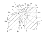
- the base inner surface 6a facing the bottom of the annular groove 12 of the base 6 of the seal member 5 is intersected at an angle of 90 degrees or more and 180 degrees or less. It is good also as the shape connected with the some surface (two surfaces in the example of FIG. 3) which has angle (alpha) 2.
- the “intersection angle” ⁇ 2 refers to an angle viewed from the inside of the seal member 5. In this case, the rigidity of the base 6 of the seal member 5 can be increased and local deformation can be prevented.
- the bottom surface 12 a of the fitting groove of the base portion 6 of the seal member 5 may be brought into contact with the base portion 6 of the seal member 5, or as in the fourth embodiment shown in FIG. 5.
- the bearing space side groove side surface 12 b of the base portion 6 of the seal member 5 and the base portion 6 of the seal member 5 may be brought into contact with each other.
- the bottom surface 12 a is a bottom surface of the annular groove 12 provided on the outer peripheral surface of the inner ring 1
- the bearing space side groove side surface 12 b is an annular surface provided on the outer peripheral surface of the inner ring 1. It is an inner surface on the inner side in the axial direction at the bottom of the groove 12.
- the bottom surface 12 a of the fitting groove and the bearing space side groove side surface 12 b may be brought into contact with the seal base 6.
- the configurations of the third to fifth embodiments shown in FIGS. 4 to 6 can increase the friction coefficient, stabilize the fixation of the seal base 6, and enhance the suppression of grease leakage from the fixed portion. . Further, since the tightness of the seal lip can be maintained, the sealing performance can be stabilized.
- FIG. 7 and 8 show an example of a wind turbine for wind power generation.
- a nacelle 23 is provided on a support base 22 so as to be horizontally rotatable, a main shaft 25 is rotatably supported in a casing 24 of the nacelle 23, and a casing 24 of the main shaft 25 is supported.
- a blade 26 which is a swirl blade is attached to one end protruding outward.
- the other end of the main shaft 25 is connected to the speed increaser 27, and the output shaft 28 of the speed increaser 27 is coupled to the rotor shaft of the generator 29.
- the nacelle 23 is rotatably supported by a swing bearing BR1.
- a slewing bearing BR1 for the nacelle 23 having a gear or the like provided on the outer peripheral surface of the outer ring 2 is used.
- a plurality of drive sources 30 are installed in the casing 24, and pinion gears are fixed to the drive sources 30 via a reduction gear (not shown). It arrange
- the outer ring 2 is connected and fixed to the support base 22 by a plurality of through holes 2 b, and the inner ring 1 is fixed to the casing 24.
- the plurality of drive sources 30 are driven in synchronization, and this turning driving force is transmitted to the outer ring 2. Therefore, the nacelle 23 can turn relative to the support base 22.
- the blade 26 is rotatably supported by the slewing bearing BR2.
- this slewing bearing BR2 in the slewing bearing of any of the embodiments described above, for example, a structure in which a gear is provided on the inner peripheral surface of the inner ring 1 is applied.
- a driving source for rotating the blade 26 is provided at the protruding end portion 25 a of the main shaft 25.
- the outer ring 2 of the slewing bearing is connected and fixed to the distal end portion 25a, and a gear attached to the inner peripheral surface of the inner ring 1 is engaged with a pinion gear of the drive source 30 (FIG. 7).
- the slewing bearing BR2 can support the wind turbine blade 26 with respect to the main shaft 25 so as to be rotatable about an axis L2 substantially perpendicular to the main shaft axis L1. In this way, the angle of the blade 26 and the direction of the nacelle 23 can be changed at any time according to the wind condition.
- the slewing bearing having any one of the above seal structures When the slewing bearing having any one of the above seal structures is used in a wind turbine for wind power generation, it is possible to prevent the lip portion 9 of the seal member 5 from being reversed and the seal member 5 from dropping off when the internal pressure is increased. As a result, the sealing performance of the seal member 5 can be maintained and grease leakage can be prevented, so that the surrounding environment can be protected and the bearing life can be extended. Further, since the sealing torque can be reduced, it is not necessary to increase the capacity of the turning torque. Therefore, it is possible to reduce the size of the drive source and reduce the manufacturing cost.
- the slewing bearings are used to slew various machines used outdoors or indoors, such as hydraulic excavators other than those for wind power generation, construction machines such as cranes, rotary tables for machine tools, gun seats, parabolic antennas, and lifting machines. It can also be applied to parts.
- the slewing bearing may be one in which the inner and outer rings have double-row raceway grooves or a cylindrical roller type (three-row cylindrical roller, cross roller).
- the main lip 7 of the lip portion 9 includes a lip body portion 7b connected to the base portion 6, and a lip protrusion portion 7c protruding from the lip body portion 7b. And have.
- the lip body portion 7b and the lip protruding portion 7c extend as an entire main lip so as to be positioned on the inner side in the axial direction of the bearing space toward the tip.
- the lip protrusion 7c is thinner than the lip body 7b.
- the lip protrusion 7c is formed in a tapered shape of the cross section that decreases in thickness toward the tip, in other words, a wedge shape.
- the main lip 7 is pressed against the seal sliding contact surface portion 2c of the concave raceway, and the base 6 Is pressed against the seal fixing side inclined portion 13a.
- the cross-sectional shape of the base inner side surface 6a facing the bottom of the annular groove 12 of the convex raceway in the base portion 6 of the seal member 5 is a shape made of one convex curve, The rigidity can be increased and local deformation can be prevented. Thereby, reversal of the lip portion 9 can be suppressed, and the seal member 5 can be prevented from falling off the raceway.
- the thickness of the lip portion 9 can be made thinner than the conventional one, and the seal torque during the bearing operation can be reduced. In addition, the sealing performance of the sealing member 5 is maintained. Since the lip protrusion 7c has a tapered cross section, when the internal pressure is applied to the seal member 5, the entire lip protrusion 7c is firmly pressed along the seal sliding contact surface portion 2c. 9 can be more reliably suppressed.
- the seal member 5 is easily fixed to the convex raceway ring. can do. Therefore, the number of assembly steps and the number of parts can be reduced, and the manufacturing cost can be reduced.
- the angle ⁇ 1 of the intersection line connecting the axial inner side surface 7a of the main lip 7 and the base inner side surface 6a of the base 6 is set to 180 degrees or more and 270 degrees or less. 7 can be positively elastically deformed. Thereby, even when the catching amount of the base portion 6 is small with respect to the annular wall portion 14, the seal member 5 can be prevented from coming out on the base portion 6 side.
- the thickness t1 of the main lip 7 is provided thinner than the radial thickness t2 of the seal body 11 of the base 6, and the thickness of the lip protrusion 7c is provided thinner than the thickness of the lip body 7b. Therefore, the sealing torque of the main lip 7 can be reduced, and when the internal pressure is applied to the seal member 5, the main lip 7 can be positively elastically deformed. As a result, the entire lip projecting portion is more firmly pressed along the seal sliding contact surface portion 2c, so that even if the hooking amount of the base portion 6 is small with respect to the annular wall portion 14, the base portion 6 side of the seal member 5 Can be prevented from coming off.
- the seal member 5 includes the auxiliary lip 8 that is in axial contact with the end surface 2d of the outer ring 2, the auxiliary lip 8 further maintains the sealing performance of the seal member 5 and has a sealing torque higher than that of the lip portion that is in radial contact. Reduction can be achieved.
- the cross-sectional shape of the base inner side surface 6a facing the bottom of the annular groove 12 in the base 6 of the seal member 5 is continuous without an inflection point. It is good also as the shape connected with the convex curve Lb, Lc, Ld which was made. These convex curves Lb, Lc, and Ld each form a convex curved surface inward in the radial direction. Also in this case, the rigidity of the entire seal member 5 can be increased and local deformation can be prevented. Thereby, reversal of the lip portion 9 can be suppressed, and the seal member 5 can be prevented from falling off the raceway.
- FIG. 12 shows an application example 3.
- This application example 3 corresponds to the second embodiment shown in FIG. 3 and has the same configuration except that the annular projecting portion 16 and the seal sliding side inclined portion 16a are not provided.
- the effect is also substantially the same as in the second embodiment, and a description thereof is omitted.
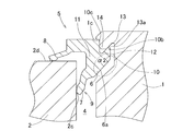
- FIG. 13 shows an application example 4.
- This application example 4 corresponds to the fifth embodiment shown in FIG. 6 and has the same structure except that the annular protrusion 16 and the seal sliding side inclined portion 16a are not provided.
- the effect is also substantially the same as in the fifth embodiment, and the description is omitted.
- the base 6 is not brought into contact with the inner side surface 15 on the axially inner side at the bottom, and the groove bottom 12a and the seal base 6 at the bottom are brought into contact as shown in FIG. 4 showing the third embodiment.
- the base 6 may not be brought into contact with the groove bottom surface 12a, but the inner surface 15 on the inner side in the axial direction at the bottom and the seal base 6 may be brought into contact as shown in FIG. 5 showing the fourth embodiment.
- the friction coefficient between the bottom and the base 6 of the seal member 5 is smaller than in the case of FIG. 13, the base 6 of the seal member 5 is stably fixed and the grease leakage from the annular groove 12 is suppressed. Can be strengthened.
- seal structures and the slewing bearings of the slewing bearings of the application examples 1 to 4 can be applied to the wind turbine of the wind power generator and other uses as in the above embodiments.
- Application examples 1 to 4 that do not have the “annular protrusion 16” as a requirement in each embodiment according to the present invention include the following modes.
- a step that is uneven in the axial direction is provided between the inner and outer rings, and includes an elastic seal member that seals the axial end of the inner and outer rings having the step
- the seal member includes a base fixed to a portion protruding from the concave raceway of the convex raceway that is the convex side of the step, and one or more that are in contact with the concave raceway that is the concave side of the step.
- a lip portion, and one of the lip portions includes a main lip that extends in an inclined manner so as to be located on the inner side in the axial direction of the bearing space toward the tip.
- a seal slidable contact surface portion that slidably contacts the main lip of the seal member;
- An annular groove is provided on the peripheral surface of the convex raceway, and a fixing groove is provided on an outer surface in the axial direction at the bottom of the annular groove, and the base portion of the seal member includes the peripheral surface of the convex raceway and the circumferential surface.
- the cross-sectional shape of the inner surface of the base facing the bottom of the annular groove of the convex raceway of the base of the seal member has an intersection angle of 90 degrees or more and 180 degrees or less. The shape was connected by a plurality of lines.
- the main lip has a lip body part connected to a base part, and a lip protrusion part protruding from the lip body part.
- the lip protrusion part is formed from the lip body part. Also reduced the thickness.
- the angle of the line of intersection connecting the axial inner side surface of the main lip and the base inner side surface of the base portion is set to 180 degrees or more and 270 degrees or less.
- the inner side surface on the inner side in the axial direction at the bottom of the annular groove of the convex bearing ring is inclined so as to be positioned on the side away from the bearing space toward the groove bottom side portion.
- a cross-sectional shape was formed.
- the bottom of the annular groove in the convex race and the base of the seal member are brought into contact with each other.
- the seal member is made of nitrile or chloroprene.
- the seal member includes, as one of the lip portions, a sub lip branched from the base portion separately from the main lip and in contact with the end surface of the concave bearing ring.
- the seal member includes, as one of the lip portions, a sub lip branched from the base portion separately from the main lip and in contact with the end surface of the concave bearing ring.
Abstract
In a seal structure for a slewing bearing, a seal member (5) has a base part (6) and lip parts (9), with one of the lip parts (9) including a main rib (7) that extends at a slant. An annular protruding part (16) that protrudes radially is provided closer to the end part than a seal sliding contact surface part (2c) at the peripheral surface of a recess-side bearing ring (2), and a seal-sliding-side slanted part (16a) that slants toward the protruding tip so as to be positioned to the outside in the axial direction is provided at the inside surface of the annular protruding part (16) in the radial direction. In a protrusion-side bearing ring (1), a seal-anchoring-side slanted part (13a) that slants toward a groove bottom-side portion so as to be positioned to the outside in the axial direction is provided at the inner surface of an anchoring groove (13) at the groove-side surface of the peripheral surface of the base part (6).
Description
本出願は、2011年3月18日出願の特願2011-060266、および2012年1月19日出願の特願2012-008553の優先権を主張するものであり、その全体を参照により本願の一部をなすものとして引用する。
This application claims the priority of Japanese Patent Application No. 2011-060266 filed on March 18, 2011 and Japanese Patent Application No. 2012-008553 filed on January 19, 2012, which is incorporated herein by reference in its entirety. Quote as part.
この発明は、例えば、風力発電装置のヨー、ブレード用の旋回座や、デッキクレーン、建設機械、物揚機械等、屋外または屋内に近接して使用される諸機械の旋回部に使用される旋回軸受のシール構造および旋回軸受に関する。
The present invention is, for example, a swivel used for a swivel part of various machines used in the vicinity of the outdoors or indoors, such as a swivel seat for a yaw and a blade of a wind power generator, a deck crane, a construction machine, and a lifting machine. The present invention relates to a seal structure of a bearing and a slewing bearing.
風力発電装置のヨー、ブレード用の旋回座等に使用される旋回軸受は、一般的にグリースにて潤滑される。この旋回軸受には、外部からの異物混入、または軸受内部からのグリース漏れを防ぐためにゴムシールが装着されている(特許文献1,2)。このゴムの材質はニトリル、クロロプレン、アクリル等が使用されている。
Slewing bearings used for wind power generation devices such as yaw and swivel seats for blades are generally lubricated with grease. This slewing bearing is provided with a rubber seal in order to prevent foreign matters from entering from outside or grease leakage from inside the bearing (Patent Documents 1 and 2). Nitrile, chloroprene, acrylic, etc. are used as the material of this rubber.
特に、風力発電装置のヨー、ブレード用の旋回軸受に使用されるゴムシールは、周辺環境保護の観点からグリース漏れ防止が重要な機能となる。旋回軸受は一般に低速運転のため、発熱の問題は少ないが、図14に示すように、給脂管50からグリースを追加給脂する等の場合には、軸心Cを有する軸受の内部の圧力が上昇する。前記給脂管50は、同図に示すように、外輪外径面51もしくは内輪内径面52から軸受内部に向かって半径方向に貫通する管である。前記のように軸受内部の圧力が上昇するため、ゴムシール部53には内部圧力が作用する。
Especially, rubber seals used for slewing bearings for yaw and blades of wind power generators have an important function of preventing grease leakage from the viewpoint of protecting the surrounding environment. Since the slewing bearing is generally operated at a low speed, there is little problem of heat generation. However, as shown in FIG. 14, when additional grease is supplied from the greasing pipe 50, the pressure inside the bearing having the shaft center C is increased. Rises. As shown in the figure, the grease supply pipe 50 is a pipe that penetrates radially from the outer ring outer diameter surface 51 or the inner ring inner diameter surface 52 toward the bearing interior. As described above, since the pressure inside the bearing rises, the internal pressure acts on the rubber seal portion 53.
ゴムシール部53に発生する内部圧力が大きい場合、シールリップ55が反転またはシール固定部より脱落するおそれがある。シールリップ55の向きは、先端に向かうに従って軸受空間の軸方向内側に傾斜して延びる内向きリップ55a、先端に向かうに従って軸受空間の軸方向外側に傾斜して延びる外向きリップ55bの2パターンがある。
When the internal pressure generated in the rubber seal portion 53 is large, the seal lip 55 may be reversed or fall off from the seal fixing portion. The direction of the seal lip 55 is two patterns: an inward lip 55a extending inwardly in the axial direction of the bearing space as it goes toward the tip, and an outward lip 55b extending inclining outward in the axial direction of the bearing space as it goes toward the tip. is there.
前記内部圧力に耐えるには、内向きリップ55aが必要となるが、この内向きリップ55aに想定以上の圧力が掛かると、リップが反転するといった不具合が生じる。その不具合を防止するための手段としては、リップの厚みを厚くし、リップ剛性を高めることが考えられる。しかし、リップの厚みを厚くすると、シールトルクが高くなり、駆動装置の仕様にも影響を及ぼすおそれがある、つまり旋回トルクの容量アップが必要となるおそれがあるため、得策とは言えない。
In order to withstand the internal pressure, an inward lip 55a is required. However, if the inward lip 55a is applied with pressure higher than expected, there is a problem that the lip is reversed. As a means for preventing the problem, it is conceivable to increase the lip rigidity by increasing the thickness of the lip. However, if the thickness of the lip is increased, the sealing torque increases, which may affect the specifications of the drive device, that is, it may be necessary to increase the capacity of the turning torque.
この発明の目的は、内部圧力の上昇時にシール部材のリップ部の反転およびシール部材の脱落を防止でき、シールトルクの低減を図ることができる旋回軸受のシール構造および旋回軸受を提供することである。
An object of the present invention is to provide a seal structure for a slewing bearing and a slewing bearing that can prevent the lip portion of the seal member from being reversed and the seal member from falling off when the internal pressure is increased, and can reduce the seal torque. .
この発明の旋回軸受のシール構造は、内輪および外輪の各軌道輪にそれぞれ軌道溝が形成され、これら内外輪の軌道溝間に複数の転動体が設けられると共に、内外輪の軸方向端に、内外輪間で軸方向に凹凸となる段差が設けられ、この段差のある内外輪の軸方向端を封止する弾性体製のシール部材を備える。前記シール部材は、前記段差の凸側となる凸側軌道輪の凹側軌道輪よりも突出した部分に固定される基部と、前記段差の凹側となる凹側軌道輪に接する1つまたは複数のリップ部とを有し、このリップ部の一つとして、先端に向かうに従って軸受空間の軸方向内側に位置するように傾斜して延びる主リップを含み、前記凹側軌道輪の軸受空間側の周面に、シール部材の主リップを摺接させるシール摺接面部を設け、凹側軌道輪の前記周面における前記シール摺接面部よりも端部側に、径方向に突出する環状突出部を設け、この環状突出部の軸方向内側面に、突出先端に向かうに従って軸方向外側に位置するように傾斜するシール摺動側傾斜部を設ける。
In the seal structure of the slewing bearing according to the present invention, a raceway groove is formed in each of the race rings of the inner ring and the outer ring, a plurality of rolling elements are provided between the race grooves of the inner and outer rings, and at the axial ends of the inner and outer rings, A step that is uneven in the axial direction is provided between the inner and outer rings, and an elastic seal member that seals the axial end of the inner and outer rings having the step is provided. The seal member includes a base fixed to a portion protruding from the concave raceway of the convex raceway that is the convex side of the step, and one or more that are in contact with the concave raceway that is the concave side of the step. One of the lip portions, and includes a main lip extending obliquely so as to be positioned on the inner side in the axial direction of the bearing space toward the tip, and on the bearing space side of the concave bearing ring. Provided on the peripheral surface is a seal slidable contact surface portion that slidably contacts the main lip of the seal member, and an annular protruding portion that protrudes in the radial direction is provided on the end side of the peripheral surface of the concave raceway. Provided on the inner surface in the axial direction of the annular protrusion is a seal sliding side inclined portion that is inclined so as to be positioned on the outer side in the axial direction toward the protruding tip.
前記凸側軌道輪の周面に環状溝を設けると共にこの環状溝の底部における軸方向外側の面に固定溝を設け、前記シール部材の前記基部は、前記凸側軌道輪における前記周面と前記固定溝の内面との間の部位である環状壁部が嵌まり込む嵌め込み用溝を有し、前記固定溝の内面における軸受空間側の溝側面に、溝底側部分に向かうに従って軸受空間から遠ざかる側に位置するように傾斜するシール固定側傾斜部を設けたものである。
An annular groove is provided on the peripheral surface of the convex raceway, and a fixing groove is provided on an outer surface in the axial direction at the bottom of the annular groove, and the base portion of the seal member includes the peripheral surface of the convex raceway and the circumferential surface. There is a groove for fitting into which the annular wall portion that is a portion between the inner surface of the fixed groove is fitted, and the groove side surface on the bearing space side of the inner surface of the fixed groove moves away from the bearing space toward the groove bottom side portion. A seal fixing side inclined portion that is inclined so as to be positioned on the side is provided.
この構成によると、シール部材に内部圧力が作用したとき、主リップが、凹側軌道輪の環状突起部のシール摺動側傾斜部に押し付けられると共に、基部が凸側軌道輪のシール固定側傾斜部に押し付けられる。つまりシール部材の主リップと基部とが両持ちで軌道輪に支持される。このとき主リップおよび基部は、対向する各傾斜部にそれぞれ面当たりするため、リップ部の反転を抑えることができ、且つ、シール部材が軌道輪から脱落することを防止することができる。これにより、リップ部の反転を防止するため、リップ部の厚みを厚くしてリップ剛性を高める必要がなくなる。したがって、リップ部の厚みを従来のものより薄肉化してシールトルクの低減を図ることができる。
According to this configuration, when internal pressure is applied to the seal member, the main lip is pressed against the seal sliding side inclined portion of the annular projection of the concave raceway, and the base is inclined to the seal fixing side of the convex raceway. Pressed against the part. That is, the main lip and the base of the seal member are both supported by the race ring. At this time, since the main lip and the base portion come into contact with the respective inclined portions facing each other, the inversion of the lip portion can be suppressed, and the seal member can be prevented from falling off the raceway. Accordingly, in order to prevent the lip portion from being reversed, it is not necessary to increase the lip rigidity by increasing the thickness of the lip portion. Therefore, the thickness of the lip portion can be made thinner than that of the conventional one, and the sealing torque can be reduced.
また凸側軌道輪の周面に設けた固定溝に、シール部材の基部の一部を差し込むことで、凸側軌道輪の周面と固定溝の内面との間の環状壁部が、基部の嵌め込み用溝に嵌まり込むため、シール部材を凸側軌道輪に容易に固定することができる。したがって、組立工数の低減を図れる。この場合、シール部材を固定するための接着剤等が不要であり、シール抑え用の蓋等の他の部品も不要となるため、部品点数の低減を図り、製造コストの低減を図れる。消耗したシール部材を交換するときの作業性も従来技術よりも大幅に向上する。
In addition, by inserting a part of the base portion of the seal member into the fixed groove provided on the peripheral surface of the convex raceway ring, the annular wall portion between the peripheral surface of the convex raceway ring and the inner surface of the fixed groove is Since the fitting member is fitted in the fitting groove, the seal member can be easily fixed to the convex race. Therefore, the number of assembly steps can be reduced. In this case, an adhesive or the like for fixing the seal member is not necessary, and other components such as a lid for suppressing the seal are also unnecessary, so that the number of components can be reduced and the manufacturing cost can be reduced. The workability when exchanging worn seal members is also greatly improved over the prior art.
前記シール部材の基部のうち、前記凸側軌道輪の前記環状溝の底部に臨む基部内側面を、一つの曲面または変曲点を持たない連続した曲面で繋がった形状としても良い。前記シール部材の基部のうち、前記凸側軌道輪の前記環状溝の底部に臨む基部内側面を、90度以上180度以下の交点角度を有する複数の面で繋がった形状としても良い。前記「交点角度」は、シール部材の内部から見た角度を言う。これらの場合、シール部材の基部の剛性を高め、局部的な変形を防止することができる。
Of the base portion of the seal member, the inner surface of the base portion facing the bottom of the annular groove of the convex raceway ring may be connected by a single curved surface or a continuous curved surface having no inflection point. Of the base portion of the seal member, the inner surface of the base portion facing the bottom portion of the annular groove of the convex raceway ring may be connected to a plurality of surfaces having intersection angles of 90 degrees or more and 180 degrees or less. The “intersection angle” refers to an angle viewed from the inside of the seal member. In these cases, the rigidity of the base portion of the seal member can be increased and local deformation can be prevented.
前記主リップの軸方向内側面と、基部の基部内側面とを繋ぐ交線の角度を180度以上270度以下としても良い。前記「角度」は、シール部材の内部から見た角度を言う。この場合、主リップの軸方向内側面と、基部の基部内側面とを繋ぐ部分に、内部圧力を作用させて主リップを積極的に弾性変形させることができる。これにより、環状壁部に対し基部の引掛かり代が少ない場合であっても、シール部材の基部側での抜け出しを防止し得る。
The angle of the intersection line connecting the axial inner side surface of the main lip and the base inner side surface of the base may be 180 degrees or more and 270 degrees or less. The “angle” refers to an angle viewed from the inside of the seal member. In this case, the main lip can be positively elastically deformed by applying an internal pressure to a portion connecting the axial inner side surface of the main lip and the base inner side surface of the base portion. Thereby, even if it is a case where the hooking amount of a base is small with respect to an annular wall part, it can prevent that the sealing member is pulled out by the base side.
前記環状突出部におけるシール摺動側傾斜部を凸側軌道輪側に延長した面と、前記固定溝のシール固定側傾斜部を凹側軌道輪側に延長した面とが交わるように、シール摺動側傾斜部およびシール固定側傾斜部を設けても良い。この場合、シール摺動側傾斜部を凸側軌道輪側に延長した面と、固定溝のシール固定側傾斜部を凹側軌道輪側に延長した面とを一平面に近づけて、シール部材に内部圧力が作用したとき、シール部材の主リップおよび基部をより確実に面当たりにすることができる。
The seal slide is formed so that the surface of the annular protrusion extending from the seal sliding side inclined portion toward the convex raceway and the surface of the fixing groove extending from the seal fixing side inclined portion toward the concave raceway are crossed. A moving side inclined portion and a seal fixing side inclined portion may be provided. In this case, the surface where the seal sliding side inclined portion is extended to the convex bearing ring side and the surface where the seal fixing side inclined portion of the fixing groove is extended to the concave bearing ring side are brought close to one plane so that the sealing member When the internal pressure is applied, the main lip and the base of the seal member can be more reliably brought into contact with the surface.
前記主リップは、基部よりも厚みを薄くしたものであっても良い。この場合、リップ部のシールトルクを低減することができ、且つ、シール部材に内部圧力が作用したとき、主リップを積極的に弾性変形させることができる。これにより、主リップが、凹側軌道輪の環状突起部のシール摺動側傾斜部に確実に押圧されるため、環状壁部に対し基部の引掛かり代が少ない場合であっても、シール部材の基部側での抜け出しを防止し得る。
The main lip may be thinner than the base. In this case, the seal torque of the lip portion can be reduced, and the main lip can be positively elastically deformed when an internal pressure is applied to the seal member. As a result, the main lip is surely pressed against the seal sliding side inclined portion of the annular projection of the concave raceway, so that the sealing member can be used even when the hooking amount of the base portion is small relative to the annular wall portion. Can be prevented from coming out on the base side.
前記シール基部の嵌め込み用溝の底面または軸受空間側溝側面とシール基部を接触させても良い。これにより、摩擦係数が大きくなり、シール基部の固定を安定させることができると共に、固定部からのグリース漏れの抑制を強化することもできる。更にシールリップの緊迫力を保持できるため、シール性を安定することもできる。
The bottom surface of the fitting groove of the seal base or the side surface of the groove on the bearing space side may be brought into contact with the seal base. As a result, the coefficient of friction is increased, the fixation of the seal base can be stabilized, and the suppression of grease leakage from the fixed part can be enhanced. Further, since the tightness of the seal lip can be maintained, the sealing performance can be stabilized.
前記シール部材はニトリルまたはクロロプレンから成るものであっても良い。前記シール部材は、リップ部の一つとして、基部から主リップとは別に分岐して凹側軌道輪の端面に接する副リップを含むものとしても良い。この副リップにより、さらにシール部材の密封性が保たれ、軸受空間からのグリース漏れ防止を図ることができる。
The sealing member may be made of nitrile or chloroprene. The seal member may include, as one of the lip portions, a sub lip branched from the base portion separately from the main lip and in contact with the end surface of the concave raceway. By this sub lip, the sealing performance of the sealing member is further maintained, and grease leakage from the bearing space can be prevented.
前記主リップの初期締代を2mm以上6mm以下としても良い。このような初期締代に設定することで、シールトルクの低減を図ると共に軸受空間からのグリース漏れ防止を図ることができる。
The initial tightening allowance of the main lip may be 2 mm or more and 6 mm or less. By setting such an initial tightening allowance, it is possible to reduce the seal torque and prevent grease leakage from the bearing space.
この発明の旋回軸受は、前記いずれかのシール構造を適用したものである。風車のブレードを主軸に対して、主軸軸心に略垂直な軸心回りに旋回自在に支持するものであっても良い。風車のナセルを支持台に対して旋回自在に支持するものであっても良い。
The slewing bearing of the present invention is one to which any of the above-mentioned seal structures is applied. A wind turbine blade may be supported so as to be rotatable about an axis substantially perpendicular to the main shaft axis with respect to the main shaft. The nacelle of the windmill may be supported so as to be rotatable with respect to the support base.
請求の範囲および/または明細書および/または図面に開示された少なくとも2つの構成のどのような組合せも、本発明に含まれる。特に、請求の範囲の各請求項の2つ以上のどのような組合せも、本発明に含まれる。
Any combination of at least two configurations disclosed in the claims and / or the specification and / or drawings is included in the present invention. In particular, any combination of two or more of each claim in the claims is included in the present invention.
この発明は、添付の図面を参考にした以下の好適な実施形態の説明から、より明瞭に理解されるであろう。しかしながら、実施形態および図面は単なる図示および説明のためのものであり、この発明の範囲を定めるために利用されるべきものではない。この発明の範囲は添付の請求の範囲によって定まる。添付図面において、複数の図面における同一の符号は、同一または相当する部分を示す。
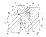
この発明の第1実施形態に係る旋回軸受の縦断面図である
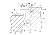
(A)は同旋回軸受のシール構造等を部分的に示す縦断面図、(B)は同シール構造のシール部材単体の縦断面図である。
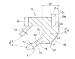
この発明の第2実施形態に係る旋回軸受のシール構造等を部分的に示す縦断面図である。
この発明の第3実施形態に係る旋回軸受のシール構造等を部分的に示す縦断面図である。
この発明の第4実施形態に係る旋回軸受のシール構造等を部分的に示す縦断面図である。
この発明の第5実施形態に係る旋回軸受のシール構造等を部分的に示す縦断面図である。
風力発電装置の一例の一部を切り欠いて表した斜視図である。
同風力発電装置の破断側面図である。
この発明の応用例1に係る旋回軸受の縦断面図である。
同旋回軸受のシール構造等を部分的に示す縦断面図である。
この発明の応用例2に係る旋回軸受のシール構造等を部分的に示す縦断面図である。
この発明の応用例3に係る旋回軸受のシール構造等を部分的に示す縦断面図である。
この発明の応用例4に係る旋回軸受のシール構造等を部分的に示す縦断面図である。
従来例の旋回軸受およびその要部の縦断面図である。
The present invention will be more clearly understood from the following description of preferred embodiments with reference to the accompanying drawings. However, the embodiments and drawings are for illustration and description only and should not be used to define the scope of the present invention. The scope of the invention is defined by the appended claims. In the accompanying drawings, the same reference numerals in a plurality of drawings indicate the same or corresponding parts.
It is a longitudinal cross-sectional view of the slewing bearing which concerns on 1st Embodiment of this invention. (A) is a longitudinal sectional view partially showing the seal structure and the like of the slewing bearing, and (B) is a longitudinal sectional view of a single seal member of the seal structure. It is a longitudinal cross-sectional view which shows partially the seal structure etc. of the slewing bearing which concern on 2nd Embodiment of this invention. It is a longitudinal cross-sectional view which shows partially the seal structure of the turning bearing etc. which concern on 3rd Embodiment of this invention. It is a longitudinal cross-sectional view which shows partially the seal structure of the turning bearing etc. which concern on 4th Embodiment of this invention. It is a longitudinal cross-sectional view which shows partially the seal structure of the turning bearing etc. which concern on 5th Embodiment of this invention. It is the perspective view which notched and represented a part of example of the wind power generator. It is a fracture side view of the wind power generator. It is a longitudinal cross-sectional view of the slewing bearing which concerns on the application example 1 of this invention. It is a longitudinal cross-sectional view which shows partially the seal structure etc. of the slewing bearing. It is a longitudinal cross-sectional view which shows partially the seal structure etc. of the slewing bearing which concerns on the application example 2 of this invention. It is a longitudinal cross-sectional view which shows partially the seal structure etc. of the slewing bearing which concerns on the application example 3 of this invention. It is a longitudinal cross-sectional view which shows partially the seal structure etc. of the slewing bearing which concerns on the application example 4 of this invention. It is a longitudinal cross-sectional view of the slewing bearing of the conventional example and its main part.
この発明の第1実施形態にかかる旋回軸受のシール構造を図1および図2(A),(B)と共に説明する。以下の説明はシール構造の設計方法についての説明をも含む。この旋回軸受は、例えば、風力発電用風車のブレードを主軸に対して、主軸軸心に略垂直な軸心回りに旋回自在に支持する軸受、または風車のナセルを支持台に対して旋回自在に支持する軸受として使用される。
A seal structure for a slewing bearing according to the first embodiment of the present invention will be described with reference to FIGS. 1 and 2A and 2B. The following description also includes a description of the design method of the seal structure. This slewing bearing is, for example, a bearing that supports the blade of a wind turbine for wind power generation so that it can pivot about an axis substantially perpendicular to the main shaft axis or a nacelle of the wind turbine relative to a support base. Used as a bearing to support.
図1に示すように、旋回軸受は、内輪1と、外輪2と、これら内外輪1,2の軌道溝1a,2a間に転動自在に介在する複数のボール3と、周方向に隣接するボール3,3間に介在する図示しない間座と、後述するシール部材5とを備える。内外輪1,2の軌道溝1a,2aは、いずれも2つの曲面で構成されている。各軌道溝1a,2aを構成する2つの曲面は、それぞれ転動体としてのボール3よりも曲率半径が大きく、曲率中心が互いに異なるゴシックアーチ状の断面円弧状である。各ボール3は、内輪軌道溝1aおよび外輪軌道溝2aの前記各曲面に接点で接して4点接触する。この旋回軸受は4点接触玉軸受として構成されている。前記間座は例えば樹脂材料からなり、この間座は両側のボール接触面が、中心部に至るに従って深く凹む球面を成す凹面形状とされている。
As shown in FIG. 1, the slewing bearing is adjacent to the inner ring 1, the outer ring 2, and a plurality of balls 3 that are rotatably interposed between the raceway grooves 1 a and 2 a of the inner and outer rings 1 and 2. A spacer (not shown) interposed between the balls 3 and 3 and a seal member 5 described later are provided. Each of the raceway grooves 1a and 2a of the inner and outer rings 1 and 2 is composed of two curved surfaces. The two curved surfaces constituting each raceway groove 1a, 2a are Gothic arch-shaped arcs having a larger radius of curvature than the balls 3 as rolling elements and different curvature centers. Each ball 3 is in contact with the curved surfaces of the inner ring raceway groove 1a and the outer ring raceway groove 2a at a point of contact with each other at four points. This slewing bearing is configured as a four-point contact ball bearing. The spacer is made of, for example, a resin material, and the spacer has a concave shape in which the ball contact surfaces on both sides form a spherical surface that is deeply recessed toward the center.
外輪2には、複数の貫通孔2bが円周方向一定間隔おきに設けられる。これら貫通孔2bは、例えば、外輪2を後述する支持台22(図7、図8)等に連結固定するために用いられる。内輪1にも複数の貫通孔1bが円周方向一定間隔おきに設けられ、これら貫通孔1bは、例えば内輪1を後述するナセル23のケーシング24(図7、図8)等に連結固定するために用いられる。各貫通孔1b,2bは、軸受軸方向に平行に形成されている。
The outer ring 2 is provided with a plurality of through holes 2b at regular intervals in the circumferential direction. These through holes 2b are used, for example, for connecting and fixing the outer ring 2 to a support base 22 (FIGS. 7 and 8) described later. The inner ring 1 is also provided with a plurality of through holes 1b at regular intervals in the circumferential direction, and these through holes 1b are used for connecting and fixing the inner ring 1 to, for example, a casing 24 (FIGS. 7 and 8) of a nacelle 23 described later. Used for. Each through- hole 1b, 2b is formed in parallel with the bearing axial direction.
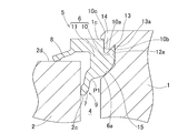
シール構造について説明する。図1に示すように、内外輪1,2の軸方向端、この例では軸方向両端に、内外輪1,2間で軸方向に凹凸となる段差δがそれぞれ設けられている。内外輪1,2の軸受空間4にはグリースが充填され、シール部材5,5は、前記段差δのある内外輪1,2の軸方向両端を封止する。軸方向一端(図1の上部)のシール部材5について説明する。図1の上部のシール部材5では、段差δの凸側となる凸側軌道輪が内輪1であり、段差δの凹側となる凹側軌道輪が外輪2となる。
The seal structure will be described. As shown in FIG. 1, steps δ that are uneven in the axial direction between the inner and outer rings 1 and 2 are provided at the axial ends of the inner and outer rings 1 and 2, in this example, at both ends in the axial direction. The bearing space 4 of the inner and outer rings 1 and 2 is filled with grease, and the seal members 5 and 5 seal both axial ends of the inner and outer rings 1 and 2 having the step δ. The seal member 5 at one end in the axial direction (upper part in FIG. 1) will be described. In the upper seal member 5 of FIG. 1, the convex raceway that is the convex side of the step δ is the inner ring 1, and the concave raceway that is the concave side of the step δ is the outer ring 2.
シール部材5は、ニトリルまたはクロロプレン等の弾性体から成り、図2(A)に示すように、基部6と、主リップ7および副リップ8を含むリップ部9とを有する。これら基部6とリップ部9とは一体に設けられる。基部6は、凸側軌道輪である内輪1に固定されるシール固定部10と、このシール固定部10に繋がるシール胴体部11とを有する。基部6のシール固定部10の内周面側に、嵌め込み用溝10aを設けている。この嵌め込み用溝10aは、軸方向外側に環状に開口するように形成されている。
The seal member 5 is made of an elastic body such as nitrile or chloroprene, and has a base portion 6 and a lip portion 9 including a main lip 7 and a sub lip 8 as shown in FIG. The base portion 6 and the lip portion 9 are provided integrally. The base portion 6 includes a seal fixing portion 10 that is fixed to the inner ring 1 that is a convex raceway ring, and a seal body portion 11 that is connected to the seal fixing portion 10. A fitting groove 10 a is provided on the inner peripheral surface side of the seal fixing portion 10 of the base portion 6. The fitting groove 10a is formed so as to open annularly outward in the axial direction.
基部6のシール固定部10は、内輪1のうち、外輪2よりも軸方向に突出した部分に固定される。内輪1の外周面に環状溝12を設けると共に、この環状溝12の底部における軸方向外側の面に、軸方向外側(軸受空間4から遠ざかる側)に向かってV字形に凹入した固定溝13を設けている。前記外周面と固定溝13の内面との間の部位である環状壁部14が、前記基部6の嵌め込み用溝10aに嵌まり込むようになっている。また、固定溝13の内面における軸受空間側の溝側面に、溝底側部分に向かうに従って軸方向外側に位置するように傾斜するシール固定側傾斜部13aを設けている。シール固定部10が内輪1に固定されたとき、前記シール固定側傾斜部13aにシール固定部10の一部である先端部10bが当接して固定されるうえ、内輪1の外周面に形成された段部1cに、シール固定部10の他の一部である係合部10cが係合して固定される。またシール部材5に内部圧力が作用したとき、シール固定部10の先端部10bがシール固定側傾斜部13aに押し付けられるようになっている。
The seal fixing portion 10 of the base portion 6 is fixed to a portion of the inner ring 1 that protrudes in the axial direction from the outer ring 2. An annular groove 12 is provided on the outer peripheral surface of the inner ring 1, and a fixed groove 13 recessed in a V shape toward the axially outer side (side away from the bearing space 4) on the axially outer surface at the bottom of the annular groove 12. Is provided. An annular wall portion 14, which is a portion between the outer peripheral surface and the inner surface of the fixed groove 13, is fitted into the fitting groove 10 a of the base portion 6. Further, on the groove side surface on the bearing space side on the inner surface of the fixed groove 13, there is provided a seal fixed side inclined portion 13 a that is inclined so as to be positioned outward in the axial direction toward the groove bottom side portion. When the seal fixing portion 10 is fixed to the inner ring 1, the tip end portion 10 b that is a part of the seal fixing portion 10 is abutted and fixed to the seal fixing side inclined portion 13 a and is formed on the outer peripheral surface of the inner ring 1. An engaging portion 10c, which is another part of the seal fixing portion 10, is engaged and fixed to the stepped portion 1c. Further, when an internal pressure is applied to the seal member 5, the tip end portion 10b of the seal fixing portion 10 is pressed against the seal fixing side inclined portion 13a.
図2(B)に示すように、シール固定部10が内輪1に固定される前のシール部材単体では、シール固定部10の先端部10bと係合部10cとの間の最大の径方向隙間δaは、シール固定部10が内輪1に固定された状態のとき(図2(A))よりも幅狭に形成される。図2(A)に示すように、内輪1の環状壁部14が嵌め込み用溝10aに嵌まり込むことで、シール固定部10の先端部10bが径方向内方に弾性変形して(換言すれば、シール固定部10の前記係合部10cに対して離隔して)シール固定側傾斜部13aに当接する。これと共に、内輪1の段部1cに、シール固定部10の係合部10cが係合するようになっている。
As shown in FIG. 2B, in the seal member alone before the seal fixing portion 10 is fixed to the inner ring 1, the largest radial clearance between the tip portion 10b of the seal fixing portion 10 and the engaging portion 10c. δa is formed to be narrower than when the seal fixing portion 10 is fixed to the inner ring 1 (FIG. 2A). 2A, when the annular wall portion 14 of the inner ring 1 is fitted into the fitting groove 10a, the tip portion 10b of the seal fixing portion 10 is elastically deformed radially inward (in other words, For example, the seal fixing part 10 is in contact with the seal fixing side inclined part 13a (separated from the engaging part 10c). At the same time, the engaging portion 10 c of the seal fixing portion 10 is engaged with the step portion 1 c of the inner ring 1.
前記環状溝12の底部における軸方向内側の内側面15は、例えば、シール固定側傾斜部13aの傾斜面に平行に形成され、シール部材5の基部6が前記内側面15および溝底面に干渉しないように設けられる。シール部材5の基部6のうち、環状溝12の底部に臨む基部内側面6aを、半径方向内方に凸曲面を成す、一つの曲面または変曲点を持たない連続した曲面で繋がった形状としている。
The inner side surface 15 on the inner side in the axial direction at the bottom of the annular groove 12 is formed, for example, in parallel with the inclined surface of the seal fixing side inclined portion 13a, and the base portion 6 of the seal member 5 does not interfere with the inner side surface 15 and the groove bottom surface. It is provided as follows. Of the base 6 of the seal member 5, the base inner side surface 6 a facing the bottom of the annular groove 12 is formed as a shape connected with a single curved surface or a continuous curved surface having no inflection point, forming a curved surface inward in the radial direction. Yes.
図2(A)に示すように、リップ部9の主リップ7は、先端に向かうに従って軸受空間の軸方向内側に位置するように傾斜して延びる。シール胴体部11のうち外輪内周面に臨むシール胴体部11の外側面部から、前記主リップ7が軸方向内側に傾斜して延びる。図2(B)に示すように、この主リップ7の厚みt1は、基部6のシール胴体部11の径方向の最大厚みt2よりも薄く設けられている。基部6のシール胴体部11のうち、環状溝12の底部に臨む基部内側面6aと、主リップ7の軸方向内側面7aとを繋ぐ交線の角度α1を、180度以上270度以下としている。この実施形態では、基部内側面6aを一つの曲面または変曲点を持たない連続した曲面で繋がった形状としているため、基部内側面6aのうち主リップ7の軸方向内側面を通る接線Laと、主リップ7の軸方向内側面とを繋ぐ交線の角度α1を、前記のように設定している。前記「角度」は、シール部材5の内部から見た角度を言う。また主リップ7の初期締代(主リップ7の先端部の、軸受への組込み前と組込み後における径方向位置の変化量)を2mm以上6mm以下に設定している。
As shown in FIG. 2 (A), the main lip 7 of the lip portion 9 extends in an inclined manner so as to be located on the inner side in the axial direction of the bearing space toward the tip. The main lip 7 extends obliquely inward in the axial direction from the outer surface of the seal body 11 facing the inner peripheral surface of the outer ring of the seal body 11. As shown in FIG. 2B, the thickness t1 of the main lip 7 is provided to be thinner than the maximum radial thickness t2 of the seal body 11 of the base 6. Of the seal body 11 of the base 6, the angle α1 of the line connecting the base inner surface 6a facing the bottom of the annular groove 12 and the axial inner surface 7a of the main lip 7 is 180 degrees or more and 270 degrees or less. . In this embodiment, since the base inner side surface 6a is connected by a single curved surface or a continuous curved surface having no inflection point, the tangent line La passing through the axial inner side surface of the main lip 7 of the base inner side surface 6a The angle α1 of the intersection line connecting the axially inner side surfaces of the main lip 7 is set as described above. The “angle” refers to an angle viewed from the inside of the seal member 5. In addition, the initial fastening allowance of the main lip 7 (the amount of change in the radial position of the tip of the main lip 7 before and after assembling into the bearing) is set to 2 mm or more and 6 mm or less.
図2(A)に示すように、凹側軌道輪である外輪2の軸受空間側の外輪内周面に、主リップ7を摺接させるシール摺接面部2cを設けている。外輪内周面における前記シール摺接面部2cよりも端部側に、径方向に突出する環状突出部16を設けている。この環状突出部16のうち軸受空間に臨む軸方向内側面に、突出先端に向かうに従って軸方向外側に位置するように傾斜するシール摺動側傾斜部16aを設けている。シール部材5に内部圧力が作用したとき、主リップ7が前記シール摺動側傾斜部16aに押し付けられるようになっている。また、シール摺動側傾斜部16aを内輪1側に延長した面S2と、固定溝13のシール固定側傾斜部13aを外輪2側に延長した面S1とが交わるように、シール摺動側傾斜部16aおよびシール固定側傾斜部13aを設けている。
As shown in FIG. 2 (A), a seal sliding contact surface portion 2c for slidingly contacting the main lip 7 is provided on the inner peripheral surface of the outer ring 2 on the bearing space side of the outer ring 2 that is a concave raceway. An annular projecting portion 16 projecting in the radial direction is provided on the inner peripheral surface of the outer ring on the end side of the seal sliding contact surface portion 2c. A seal sliding side inclined portion 16a that is inclined so as to be positioned on the outer side in the axial direction toward the protruding tip is provided on the inner surface in the axial direction facing the bearing space in the annular protruding portion 16. When an internal pressure is applied to the seal member 5, the main lip 7 is pressed against the seal sliding side inclined portion 16a. Further, the seal sliding side slope 16 so that the surface S2 extending the seal sliding side inclined portion 16a to the inner ring 1 side and the surface S1 extending the seal fixing side inclined portion 13a of the fixing groove 13 to the outer ring 2 side intersect. A portion 16a and a seal fixing side inclined portion 13a are provided.
リップ部9の副リップ8は、基部6のシール胴体部11から主リップ7とは別に分岐して、外輪2の端面2dに接する。つまりシール胴体部11のうち外輪2の端面2dに臨む下端面部から、前記副リップ8が軸方向内側に傾斜して延び、外輪2の端面2dにアキシアル接触する。図2(B)に示すように、この副リップ8の厚みt3は、シール胴体部11の軸方向の厚みt4よりも薄く設けられている。前記副リップ8は、ダストリップとも言う。
The auxiliary lip 8 of the lip portion 9 branches from the seal body portion 11 of the base portion 6 separately from the main lip 7 and contacts the end surface 2d of the outer ring 2. That is, the sub lip 8 extends in an axially inclining manner from the lower end surface portion of the seal body portion 11 facing the end surface 2d of the outer ring 2, and makes axial contact with the end surface 2d of the outer ring 2. As shown in FIG. 2B, the thickness t3 of the sub lip 8 is provided thinner than the thickness t4 of the seal body 11 in the axial direction. The secondary lip 8 is also called a dust lip.
なお、図1に示すように、内外輪1,2の軸方向他端(図1の下部)では、段差δの凸側となる凸側軌道輪が外輪2であり、段差δの凹側となる凹側軌道輪が内輪1となる。この軸方向他端に設けられるシール構造については、軸方向一端のシール構造と同一構造であるので、同シール構造に付した符号と同一の符号を付してその説明を省略する。
As shown in FIG. 1, at the other axial end of the inner and outer rings 1 and 2 (lower part in FIG. 1), the convex raceway ring that is the convex side of the step δ is the outer ring 2, and the concave side of the step δ The concave raceway ring is the inner ring 1. Since the seal structure provided at the other end in the axial direction is the same as the seal structure at one end in the axial direction, the same reference numerals as those assigned to the seal structure are attached and the description thereof is omitted.
以上説明した旋回軸受のシール構造によると、シール部材5に内部圧力が作用したとき、主リップ7が、凹側軌道輪の環状突起部16のシール摺動側傾斜部16aに押し付けられると共に、基部6が凸側軌道輪のシール固定側傾斜部13aに押し付けられる。つまりシール部材5の主リップ7と基部6とが両持ちで軌道輪に支持される。このとき主リップ7および基部6は、対向する各傾斜部16a,13aにそれぞれ面当たりするため、リップ部9の反転を抑えることができ、且つ、シール部材5が軌道輪から脱落することを防止することができる。これにより、リップ部の反転を防止するため、リップ部の厚みを厚くしてリップ剛性を高める必要がなくなる。したがって、リップ部9の厚みを従来のものより薄肉化してシールトルクの低減を図ることができる。
According to the seal structure of the slewing bearing described above, when the internal pressure is applied to the seal member 5, the main lip 7 is pressed against the seal sliding side inclined portion 16a of the annular protrusion 16 of the concave raceway, and the base portion 6 is pressed against the seal fixing side inclined portion 13a of the convex raceway. That is, the main lip 7 and the base 6 of the seal member 5 are both supported by the raceway ring. At this time, the main lip 7 and the base portion 6 come into contact with the respective inclined portions 16a and 13a facing each other, so that the inversion of the lip portion 9 can be suppressed and the seal member 5 is prevented from falling off the raceway. can do. Accordingly, in order to prevent the lip portion from being reversed, it is not necessary to increase the lip rigidity by increasing the thickness of the lip portion. Therefore, the thickness of the lip portion 9 can be made thinner than that of the conventional one, and the sealing torque can be reduced.
また、凸側軌道輪の周面に設けた固定溝13に、シール部材5の基部6を差し込むことで、凸側軌道輪の周面と固定溝13の内面との間の環状壁部14が、基部6の嵌め込み用溝10aに嵌まり込むため、シール部材5を凸側軌道輪に容易に固定することができる。したがって、組立工数の低減を図れる。この場合、シール部材5を固定するための接着剤等が不要であり、シール抑え用の蓋等の他の部品も不要となるため、部品点数の低減を図り、製造コストの低減を図れる。消耗したシール部材5を交換するときの作業性も従来技術よりも大幅に向上する。
Further, by inserting the base portion 6 of the seal member 5 into the fixed groove 13 provided on the peripheral surface of the convex side race ring, the annular wall portion 14 between the peripheral surface of the convex side race ring and the inner surface of the fixed groove 13 is formed. Since it fits in the fitting groove 10a of the base 6, the seal member 5 can be easily fixed to the convex raceway. Therefore, the number of assembly steps can be reduced. In this case, an adhesive or the like for fixing the seal member 5 is not necessary, and other components such as a lid for suppressing the seal are also unnecessary, so that the number of components can be reduced and the manufacturing cost can be reduced. The workability when replacing the worn seal member 5 is also greatly improved as compared with the prior art.
シール部材5の基部6のうち、前記環状溝12の底部に臨む基部内側面6aを、一つの曲面または変曲点を持たない連続した曲面で繋がった形状としたため、シール部材5の基部6の剛性を高め、局部的な変形を防止することができる。図2(B)に示すように、主リップ7の軸方向内側面7aと、基部6の基部内側面6aとを繋ぐ交線の角度α1を180度以上270度以下としたため、主リップ7の軸方向内側面7aと、基部6の基部内側面6aとを繋ぐ部分P1に、内部圧力を作用させて主リップ7を積極的に弾性変形させることができる。これにより、環状壁部14に対し基部6の引掛かり代が少ない場合であっても、シール部材5の基部6側での抜け出しを防止し得る。
Of the base 6 of the seal member 5, the base inner side surface 6 a facing the bottom of the annular groove 12 has a shape connected by a single curved surface or a continuous curved surface having no inflection point. The rigidity can be increased and local deformation can be prevented. As shown in FIG. 2B, the angle α1 of the line connecting the axial inner side surface 7a of the main lip 7 and the base inner side surface 6a of the base 6 is set to 180 degrees or more and 270 degrees or less. The main lip 7 can be positively elastically deformed by applying an internal pressure to a portion P <b> 1 connecting the axial inner side surface 7 a and the base inner side surface 6 a of the base 6. Thereby, even when the catching amount of the base portion 6 is small with respect to the annular wall portion 14, the seal member 5 can be prevented from coming out on the base portion 6 side.
図2(A)に示すように、環状突出部16におけるシール摺動側傾斜部16aを凸側軌道輪側に延長した面S2と、前記固定溝13のシール固定側傾斜部13aを凹側軌道輪側に延長した面S1とが交わるように、シール摺動側傾斜部16aおよびシール固定側傾斜部13aを設けたため、以下の作用効果を奏する。すなわち、シール摺動側傾斜部16aを凸側軌道輪側に延長した面S2と、固定溝13のシール固定側傾斜部13aを凹側軌道輪側に延長した面S1とが一平面に近づくので、シール部材5に内部圧力が作用したとき、シール部材5の主リップ7および基部6をより確実に面当たりにすることができる。
As shown in FIG. 2A, the surface S2 of the annular protrusion 16 extending the seal sliding side inclined portion 16a to the convex raceway side, and the seal fixing side inclined portion 13a of the fixing groove 13 is set to the concave side track. Since the seal sliding side inclined portion 16a and the seal fixing side inclined portion 13a are provided so as to intersect with the surface S1 extended to the ring side, the following effects are obtained. That is, the surface S2 obtained by extending the seal sliding side inclined portion 16a toward the convex raceway and the surface S1 obtained by extending the seal fixing side inclined portion 13a of the fixing groove 13 toward the concave raceway are close to one plane. When the internal pressure is applied to the seal member 5, the main lip 7 and the base portion 6 of the seal member 5 can be brought into contact with each other more reliably.
図2(B)に示すように、主リップ7の厚みt1は、基部6のシール胴体部11の径方向の厚みt2よりも薄く設けられているため、主リップ7のシールトルクを低減することができ、且つ、シール部材5に内部圧力が作用したとき、主リップ7を積極的に弾性変形させることができる。これにより、主リップ7が、凹側軌道輪の環状突起部16のシール摺動側傾斜部16aに確実に押圧されるため、環状壁部14に対し基部6の引掛かり代が少ない場合であっても、シール部材5の基部6側での抜け出しを防止し得る。
As shown in FIG. 2 (B), the thickness t1 of the main lip 7 is provided thinner than the radial thickness t2 of the seal body 11 of the base 6, so that the seal torque of the main lip 7 is reduced. When the internal pressure acts on the seal member 5, the main lip 7 can be positively elastically deformed. As a result, the main lip 7 is surely pressed against the seal sliding side inclined portion 16a of the annular projection 16 of the concave raceway ring, so that the base 6 is less likely to be caught with respect to the annular wall portion 14. However, it is possible to prevent the seal member 5 from coming out on the base 6 side.
シール部材5は、外輪2の端面2dに接する副リップ8を含むため、この副リップ8により、さらにシール部材5の密封性が保たれ、軸受空間4からのグリース漏れ防止を図ることができる。この副リップ8はアキシアル接触するものであるため、ラジアル接触するリップ部よりもシールトルクの低減を図れる。
Since the seal member 5 includes the secondary lip 8 that contacts the end surface 2d of the outer ring 2, the secondary lip 8 can further maintain the sealing performance of the seal member 5 and prevent grease leakage from the bearing space 4. Since the secondary lip 8 is in axial contact, the sealing torque can be reduced more than the lip portion in radial contact.
シール構造の他の例として、図3に示す第2実施形態のように、シール部材5の基部6のうち、前記環状溝12の底部に臨む基部内側面6aを90度以上180度以下の交点角度α2を有する複数の面(図3の例では2つの面)で繋がった形状としても良い。前記「交点角度」α2は、シール部材5の内部から見た角度を言う。この場合、シール部材5の基部6の剛性を高め、局部的な変形を防止することができる。
As another example of the seal structure, as in the second embodiment shown in FIG. 3, the base inner surface 6a facing the bottom of the annular groove 12 of the base 6 of the seal member 5 is intersected at an angle of 90 degrees or more and 180 degrees or less. It is good also as the shape connected with the some surface (two surfaces in the example of FIG. 3) which has angle (alpha) 2. The “intersection angle” α2 refers to an angle viewed from the inside of the seal member 5. In this case, the rigidity of the base 6 of the seal member 5 can be increased and local deformation can be prevented.
図4に示す第3実施形態のように、シール部材5の基部6の嵌め込み用溝の底面12aとシール部材5の基部6を接触させても良いし、図5に示す第4実施形態のように、シール部材5の基部6の軸受空間側溝側面12bとシール部材5の基部6を接触させても良い。第3実施形態において、前記底面12aは、内輪1の外周面に設けた環状溝12の底面であり、第4実施形態において、前記軸受空間側溝側面12bは、内輪1の外周面に設けた環状溝12の底部における軸方向内側の内側面である。
As in the third embodiment shown in FIG. 4, the bottom surface 12 a of the fitting groove of the base portion 6 of the seal member 5 may be brought into contact with the base portion 6 of the seal member 5, or as in the fourth embodiment shown in FIG. 5. Furthermore, the bearing space side groove side surface 12 b of the base portion 6 of the seal member 5 and the base portion 6 of the seal member 5 may be brought into contact with each other. In the third embodiment, the bottom surface 12 a is a bottom surface of the annular groove 12 provided on the outer peripheral surface of the inner ring 1, and in the fourth embodiment, the bearing space side groove side surface 12 b is an annular surface provided on the outer peripheral surface of the inner ring 1. It is an inner surface on the inner side in the axial direction at the bottom of the groove 12.
図6に示す第5実施形態のように、嵌め込み用溝の底面12aおよび軸受空間側溝側面12bと、シール基部6とを接触させても良い。これら図4~6に示す第3~5実施形態の構成により、摩擦係数が大きくなり、シール基部6の固定を安定させることができると共に、固定部からのグリース漏れの抑制を強化することもできる。更にシールリップの緊迫力を保持できるため、シール性を安定することもできる。
As in the fifth embodiment shown in FIG. 6, the bottom surface 12 a of the fitting groove and the bearing space side groove side surface 12 b may be brought into contact with the seal base 6. The configurations of the third to fifth embodiments shown in FIGS. 4 to 6 can increase the friction coefficient, stabilize the fixation of the seal base 6, and enhance the suppression of grease leakage from the fixed portion. . Further, since the tightness of the seal lip can be maintained, the sealing performance can be stabilized.
図7および図8は風力発電用の風車の一例を示す。これらの図に示すように、この風車21は、支持台22上にナセル23を水平旋回自在に設け、このナセル23のケーシング24内に主軸25を回転自在に支持し、この主軸25のケーシング24外に突出した一端に、旋回翼であるブレード26を取付けてなる。主軸25の他端は増速機27に接続され、増速機27の出力軸28が発電機29のロータ軸に結合されている。
7 and 8 show an example of a wind turbine for wind power generation. As shown in these drawings, in the wind turbine 21, a nacelle 23 is provided on a support base 22 so as to be horizontally rotatable, a main shaft 25 is rotatably supported in a casing 24 of the nacelle 23, and a casing 24 of the main shaft 25 is supported. A blade 26 which is a swirl blade is attached to one end protruding outward. The other end of the main shaft 25 is connected to the speed increaser 27, and the output shaft 28 of the speed increaser 27 is coupled to the rotor shaft of the generator 29.
図8に示すように、ナセル23は、旋回軸受BR1により旋回自在に支持される。前述したいずれかの実施形態の旋回軸受において、例えば、外輪2の外周面にギヤ等が設けられたものが、前記ナセル23用の旋回軸受BR1に用いられる。また、図7に示すように、ケーシング24に複数の駆動源30が設置され、各駆動源30に図示しない減速機を介してピニオンギヤが固着される。外輪2(図1)の前記ギヤが前記ピニオンギヤに噛合するように配置される。例えば、外輪2が複数の貫通孔2bにより支持台22に連結固定され、内輪1がケーシング24に固定される。複数の駆動源30を同期して駆動させ、この旋回駆動力を外輪2へ伝達する。よって、支持台22に対してナセル23が相対的に旋回可能となる。
As shown in FIG. 8, the nacelle 23 is rotatably supported by a swing bearing BR1. In the slewing bearing of any one of the embodiments described above, for example, a slewing bearing BR1 for the nacelle 23 having a gear or the like provided on the outer peripheral surface of the outer ring 2 is used. Further, as shown in FIG. 7, a plurality of drive sources 30 are installed in the casing 24, and pinion gears are fixed to the drive sources 30 via a reduction gear (not shown). It arrange | positions so that the said gear of the outer ring | wheel 2 (FIG. 1) may mesh | engage with the said pinion gear. For example, the outer ring 2 is connected and fixed to the support base 22 by a plurality of through holes 2 b, and the inner ring 1 is fixed to the casing 24. The plurality of drive sources 30 are driven in synchronization, and this turning driving force is transmitted to the outer ring 2. Therefore, the nacelle 23 can turn relative to the support base 22.
ブレード26は、旋回軸受BR2により旋回自在に支持される。この旋回軸受BR2は、前述したいずれかの実施形態の旋回軸受において、例えば、内輪1の内周面にギヤを設けたものが適用される。図8に示すように、主軸25の突出した先端部25aには、ブレード26を旋回駆動する駆動源が設けられる。前記先端部25aにこの旋回軸受の外輪2が連結固定され、内輪1の内周面に付設のギヤが、前記駆動源30(図7)のピニオンギヤに噛合されている。この駆動源30を駆動させ、この旋回駆動力を内輪1に伝達することで、ブレード26が旋回可能となる。したがって、旋回軸受BR2は、風車のブレード26を主軸25に対して、主軸軸心L1に略垂直な軸心L2回りに旋回自在に支持し得る。このように、ブレード26の角度およびナセル23の向きを風の状態に合わせて随時変え得る。
The blade 26 is rotatably supported by the slewing bearing BR2. As this slewing bearing BR2, in the slewing bearing of any of the embodiments described above, for example, a structure in which a gear is provided on the inner peripheral surface of the inner ring 1 is applied. As shown in FIG. 8, a driving source for rotating the blade 26 is provided at the protruding end portion 25 a of the main shaft 25. The outer ring 2 of the slewing bearing is connected and fixed to the distal end portion 25a, and a gear attached to the inner peripheral surface of the inner ring 1 is engaged with a pinion gear of the drive source 30 (FIG. 7). By driving the drive source 30 and transmitting the turning driving force to the inner ring 1, the blade 26 can turn. Therefore, the slewing bearing BR2 can support the wind turbine blade 26 with respect to the main shaft 25 so as to be rotatable about an axis L2 substantially perpendicular to the main shaft axis L1. In this way, the angle of the blade 26 and the direction of the nacelle 23 can be changed at any time according to the wind condition.
前記いずれかのシール構造を有する旋回軸受を、風力発電用の風車に用いた場合、内部圧力の上昇時にシール部材5のリップ部9の反転およびシール部材5の脱落を防止できる。これにより、シール部材5の密封性が保たれ、グリース漏れ防止を図ることができるため、周辺環境を保護することができるうえ、軸受寿命を延ばすことができる。さらに、シールトルクの低減を図ることができるため、旋回トルクの容量を増やす必要がなくなる。したがって駆動源の小形化を図れ、製造コストの低減を図れる。
When the slewing bearing having any one of the above seal structures is used in a wind turbine for wind power generation, it is possible to prevent the lip portion 9 of the seal member 5 from being reversed and the seal member 5 from dropping off when the internal pressure is increased. As a result, the sealing performance of the seal member 5 can be maintained and grease leakage can be prevented, so that the surrounding environment can be protected and the bearing life can be extended. Further, since the sealing torque can be reduced, it is not necessary to increase the capacity of the turning torque. Therefore, it is possible to reduce the size of the drive source and reduce the manufacturing cost.
これらの旋回軸受を、風力発電用以外の油圧ショベル、クレーン等の建設機械、工作機械の回転テーブル、砲座、パラボラアンテナ、物揚機械等、屋外または屋内に近接して使用される諸機械の旋回部等にも適用できる。旋回軸受は、内外輪が複列の軌道溝を有するものや円筒ころタイプ(3列円筒ころ、クロスローラ)であってもよい。
These slewing bearings are used to slew various machines used outdoors or indoors, such as hydraulic excavators other than those for wind power generation, construction machines such as cranes, rotary tables for machine tools, gun seats, parabolic antennas, and lifting machines. It can also be applied to parts. The slewing bearing may be one in which the inner and outer rings have double-row raceway grooves or a cylindrical roller type (three-row cylindrical roller, cross roller).
つぎに、この発明の応用例1~4について図9ないし図13と共に説明する。これらの図に示す応用例では、前記各第実施形態における環状突出部16およびシール摺動側傾斜部16aを省略したもので、その他の構成は前記各実施形態と同様であるので、各実施形態の構成と同一または相当する部分には同一の符号を付してその詳しい説明は省略する。
Next, application examples 1 to 4 of the present invention will be described with reference to FIGS. In the application examples shown in these drawings, the annular protrusion 16 and the seal sliding side inclined portion 16a in each of the above-described embodiments are omitted, and other configurations are the same as those of the above-described embodiments. Parts that are the same as or correspond to those in FIG.
図9および図10に示す応用例1では、図10に示すように、リップ部9の主リップ7は、基部6に繋がるリップ胴体部7bと、このリップ胴体部7bから突出するリップ突出部7cとを有する。これらリップ胴体部7bおよびリップ突出部7cは、主リップ全体として、先端に向かうに従って軸受空間の軸方向内側に位置するように傾斜して延びる。リップ突出部7cは、リップ胴体部7bよりも厚みを薄くしている。またリップ突出部7cは、先端に向かうに従って厚みが薄くなる断面先細り形状、換言すれば、くさび形状に形成されている。
In the application example 1 shown in FIGS. 9 and 10, as shown in FIG. 10, the main lip 7 of the lip portion 9 includes a lip body portion 7b connected to the base portion 6, and a lip protrusion portion 7c protruding from the lip body portion 7b. And have. The lip body portion 7b and the lip protruding portion 7c extend as an entire main lip so as to be positioned on the inner side in the axial direction of the bearing space toward the tip. The lip protrusion 7c is thinner than the lip body 7b. Further, the lip protrusion 7c is formed in a tapered shape of the cross section that decreases in thickness toward the tip, in other words, a wedge shape.
この応用例1の場合、例えば、前記給脂管から軸受内部にグリースを追加給脂することでシール部材5に内部圧力が作用したとき、主リップ7のリップ突出部7cがシール摺接面部2cに押し付けられる。このときリップ突出部7cが前述の断面先細り形状に形成されているため、リップ突出部7c全体がシール摺接面部2cに沿って強固に押し付けられるようになっている。
In the case of this application example 1, for example, when internal pressure is applied to the seal member 5 by adding grease to the inside of the bearing from the grease supply pipe, the lip protruding portion 7c of the main lip 7 becomes the seal sliding contact surface portion 2c. Pressed against. At this time, since the lip protrusion 7c is formed in the aforementioned tapered shape in cross section, the entire lip protrusion 7c is firmly pressed along the seal sliding contact surface portion 2c.
作用効果について説明する。例えば、前記給脂管から軸受内部にグリースを追加給脂することで、シール部材5に内部圧力が作用したとき、主リップ7が凹側軌道輪のシール摺接面部2cに押し付けられ、基部6がシール固定側傾斜部13aに押し付けられる。このとき、シール部材5の基部6のうち、凸側軌道輪の前記環状溝12の底部に臨む基部内側面6aの断面形状を、一つの凸状の曲線からなる形状としたため、シール部材全体の剛性を高め、局所的な変形を防止することができる。これにより、リップ部9の反転を抑えることができ、且つ、シール部材5が軌道輪から脱落することを防止することができる。内部圧力に耐えることができリップ部9の反転を抑えることができるため、リップ部9の厚みを厚くしてリップ剛性を高める必要がなくなる。したがって、リップ部9の厚みを従来のものより薄肉化して、軸受運転時のシールトルクの低減を図ることができる。しかもシール部材5の密封性が保たれる。前記リップ突出部7cが断面先細り形状に形成されているため、シール部材5に内部圧力が作用したとき、リップ突出部7c全体がシール摺接面部2cに沿って強固に押し付けられることで、リップ部9の反転をより確実に抑えることができる。
Describe the effects. For example, when the internal pressure is applied to the seal member 5 by additionally supplying grease into the bearing from the greasing pipe, the main lip 7 is pressed against the seal sliding contact surface portion 2c of the concave raceway, and the base 6 Is pressed against the seal fixing side inclined portion 13a. At this time, since the cross-sectional shape of the base inner side surface 6a facing the bottom of the annular groove 12 of the convex raceway in the base portion 6 of the seal member 5 is a shape made of one convex curve, The rigidity can be increased and local deformation can be prevented. Thereby, reversal of the lip portion 9 can be suppressed, and the seal member 5 can be prevented from falling off the raceway. Since it can withstand the internal pressure and the reversal of the lip portion 9 can be suppressed, it is not necessary to increase the lip rigidity by increasing the thickness of the lip portion 9. Therefore, the thickness of the lip portion 9 can be made thinner than the conventional one, and the seal torque during the bearing operation can be reduced. In addition, the sealing performance of the sealing member 5 is maintained. Since the lip protrusion 7c has a tapered cross section, when the internal pressure is applied to the seal member 5, the entire lip protrusion 7c is firmly pressed along the seal sliding contact surface portion 2c. 9 can be more reliably suppressed.
また、凸側軌道輪の周面と固定溝13の内面との間の環状壁部14が、基部6の嵌め込み用溝10aに嵌まり込むため、シール部材5を凸側軌道輪に容易に固定することができる。したがって、組立工数および部品点数の低減を図り、製造コストの低減を図れる。
Further, since the annular wall portion 14 between the peripheral surface of the convex raceway ring and the inner surface of the fixing groove 13 is fitted into the fitting groove 10a of the base portion 6, the seal member 5 is easily fixed to the convex raceway ring. can do. Therefore, the number of assembly steps and the number of parts can be reduced, and the manufacturing cost can be reduced.
図2(B)を用いて説明したとおり、主リップ7の軸方向内側面7aと、基部6の基部内側面6aとを繋ぐ交線の角度α1を180度以上270度以下としたため、主リップ7を積極的に弾性変形させることができる。これにより、環状壁部14に対し基部6の引掛かり代が少ない場合であっても、シール部材5の基部6側での抜け出しを防止し得る。
As described with reference to FIG. 2B, the angle α1 of the intersection line connecting the axial inner side surface 7a of the main lip 7 and the base inner side surface 6a of the base 6 is set to 180 degrees or more and 270 degrees or less. 7 can be positively elastically deformed. Thereby, even when the catching amount of the base portion 6 is small with respect to the annular wall portion 14, the seal member 5 can be prevented from coming out on the base portion 6 side.
主リップ7の厚みt1は、基部6のシール胴体部11の径方向の厚みt2よりも薄く設けられており、さらにリップ突出部7cの厚みは、リップ胴体部7bの厚みよりも薄く設けられているため、主リップ7のシールトルクを低減することができ、且つ、シール部材5に内部圧力が作用したとき、主リップ7を積極的に弾性変形させることができる。これにより、リップ突出部全体がシール摺接面部2cに沿ってより強固に押し付けられるため、環状壁部14に対し基部6の引掛かり代が少ない場合であっても、シール部材5の基部6側での抜け出しを防止し得る。
The thickness t1 of the main lip 7 is provided thinner than the radial thickness t2 of the seal body 11 of the base 6, and the thickness of the lip protrusion 7c is provided thinner than the thickness of the lip body 7b. Therefore, the sealing torque of the main lip 7 can be reduced, and when the internal pressure is applied to the seal member 5, the main lip 7 can be positively elastically deformed. As a result, the entire lip projecting portion is more firmly pressed along the seal sliding contact surface portion 2c, so that even if the hooking amount of the base portion 6 is small with respect to the annular wall portion 14, the base portion 6 side of the seal member 5 Can be prevented from coming off.
シール部材5は、外輪2の端面2dにアキシアル接触する副リップ8を含むため、この副リップ8により、さらにシール部材5の密封性が保たれるとともに、ラジアル接触するリップ部よりもシールトルクの低減を図れる。
Since the seal member 5 includes the auxiliary lip 8 that is in axial contact with the end surface 2d of the outer ring 2, the auxiliary lip 8 further maintains the sealing performance of the seal member 5 and has a sealing torque higher than that of the lip portion that is in radial contact. Reduction can be achieved.
シール構造の他の例として、図11に示す応用例2のように、シール部材5の基部6における、環状溝12の底部に臨む基部内側面6aの断面形状を、変曲点を持たない連続した凸状の曲線Lb,Lc,Ldで繋がった形状としても良い。これら凸状の曲線Lb,Lc,Ldは、それぞれ半径方向内方に凸曲面を成す。この場合にもシール部材5全体の剛性を高め、局所的な変形を防止することができる。これにより、リップ部9の反転を抑えることができ、且つ、シール部材5が軌道輪から脱落することを防止することができる。
As another example of the seal structure, as in Application Example 2 shown in FIG. 11, the cross-sectional shape of the base inner side surface 6a facing the bottom of the annular groove 12 in the base 6 of the seal member 5 is continuous without an inflection point. It is good also as the shape connected with the convex curve Lb, Lc, Ld which was made. These convex curves Lb, Lc, and Ld each form a convex curved surface inward in the radial direction. Also in this case, the rigidity of the entire seal member 5 can be increased and local deformation can be prevented. Thereby, reversal of the lip portion 9 can be suppressed, and the seal member 5 can be prevented from falling off the raceway.
図12は応用例3を示す。この応用例3は、図3に示す第2実施形態に対応するもので、環状突出部16およびシール摺動側傾斜部16aを有していない点を除き、同一の構成であるので、作用および効果についても第2実施形態とほぼ同様であり、説明を省略する。
FIG. 12 shows an application example 3. This application example 3 corresponds to the second embodiment shown in FIG. 3 and has the same configuration except that the annular projecting portion 16 and the seal sliding side inclined portion 16a are not provided. The effect is also substantially the same as in the second embodiment, and a description thereof is omitted.
図13は応用例4を示す。この応用例4は、図6に示す第5実施形態に対応するもので、環状突出部16およびシール摺動側傾斜部16aを有していない点を除き、同一の構成であるので、作用および効果についても第5実施形態とほぼ同様であり、説明を省略する。
FIG. 13 shows an application example 4. This application example 4 corresponds to the fifth embodiment shown in FIG. 6 and has the same structure except that the annular protrusion 16 and the seal sliding side inclined portion 16a are not provided. The effect is also substantially the same as in the fifth embodiment, and the description is omitted.
なお図示しないが、前記底部における軸方向内側の内側面15に基部6を接触させないで、第3実施形態を示す図4のように、底部における溝底面12aとシール基部6とを接触させても良いし、前記溝底面12aに基部6を接触させないで、第4実施形態を示す図5のように底部における軸方向内側の内側面15とシール基部6とを接触させても良い。これらの場合、図13の場合よりも、底部とシール部材5の基部6との摩擦係数は小さくなるものの、シール部材5の基部6の固定を安定させると共に、環状溝12からのグリース漏れの抑制を強化することができる。
Although not shown, the base 6 is not brought into contact with the inner side surface 15 on the axially inner side at the bottom, and the groove bottom 12a and the seal base 6 at the bottom are brought into contact as shown in FIG. 4 showing the third embodiment. Alternatively, the base 6 may not be brought into contact with the groove bottom surface 12a, but the inner surface 15 on the inner side in the axial direction at the bottom and the seal base 6 may be brought into contact as shown in FIG. 5 showing the fourth embodiment. In these cases, although the friction coefficient between the bottom and the base 6 of the seal member 5 is smaller than in the case of FIG. 13, the base 6 of the seal member 5 is stably fixed and the grease leakage from the annular groove 12 is suppressed. Can be strengthened.
これら応用例1~4の旋回軸受のシール構造および旋回軸受も、前記各実施形態と同様、風力発電装置の風車および他の用途に適用できるのはいうまでもない。
Needless to say, the seal structures and the slewing bearings of the slewing bearings of the application examples 1 to 4 can be applied to the wind turbine of the wind power generator and other uses as in the above embodiments.
この発明にかかる各実施形態で要件とした「環状突出部16」を有しない応用例1~4は、以下の態様を含む。
[態様1]
態様1に係る旋回軸受のシール構造は、内輪および外輪の各軌道輪にそれぞれ軌道溝が形成され、これら内外輪の軌道溝間に複数の転動体が設けられると共に、内外輪の軸方向端に、内外輪間で軸方向に凹凸となる段差が設けられ、この段差のある内外輪の軸方向端を封止する弾性体製のシール部材を備え、
前記シール部材は、前記段差の凸側となる凸側軌道輪の凹側軌道輪よりも突出した部分に固定される基部と、前記段差の凹側となる凹側軌道輪に接する1つまたは複数のリップ部とを有し、このリップ部の一つとして、先端に向かうに従って軸受空間の軸方向内側に位置するように傾斜して延びる主リップを含み、
前記凹側軌道輪の軸受空間側の周面に、シール部材の主リップを摺接させるシール摺接面部を設け、
前記凸側軌道輪の周面に環状溝を設けると共にこの環状溝の底部における軸方向外側の面に固定溝を設け、前記シール部材の前記基部は、前記凸側軌道輪における前記周面と前記固定溝の内面との間の部位である環状壁部が嵌まり込む嵌め込み用溝を有し、前記固定溝の内面における軸受空間側の溝側面に、溝底側部分に向かうに従って軸受空間から遠ざかる側に位置するように傾斜するシール固定側傾斜部を設け、
前記シール部材の基部のうち、前記凸側軌道輪の前記環状溝の底部に臨む基部内側面の断面形状を、一つの凸状の曲線または変曲点を持たない連続した凸状の曲線で繋がった形状としたものである。
[態様2]
態様1に係る旋回軸受のシール構造において、前記シール部材の基部のうち、前記凸側軌道輪の前記環状溝の底部に臨む基部内側面の断面形状を、90度以上180度以下の交点角度を有する複数の線で繋がった形状とした。
[態様3]
態様1に係る旋回軸受のシール構造において、前記主リップは、基部に繋がるリップ胴体部と、このリップ胴体部から突出するリップ突出部とを有し、このリップ突出部は、前記リップ胴体部よりも厚みを薄くした。
[態様4]
態様2に係る旋回軸受のシール構造において、前記主リップの軸方向内側面と、基部の基部内側面とを繋ぐ交線の角度を180度以上270度以下とした。
[態様5]
態様1に係る旋回軸受のシール構造において、前記凸側軌道輪の前記環状溝の底部における軸方向内側の内側面を、溝底側部分に向かうに従って軸受空間から遠ざかる側に位置するように傾斜する断面形状に形成した。
[態様6]
態様1に係る旋回軸受のシール構造において、前記凸側軌道輪における前記環状溝の底部と、シール部材の基部とを接触させた。
[態様7]
態様1に係る旋回軸受のシール構造において、前記シール部材はニトリルまたはクロロプレンから成る。
[態様8]
態様1に係る旋回軸受のシール構造において、前記シール部材は、リップ部の一つとして、基部から主リップとは別に分岐して凹側軌道輪の端面に接する副リップを含む。
[態様9]
態様1に係る旋回軸受のシール構造において、前記各態様のいずれかシール構造を適用した旋回軸受。 Application examples 1 to 4 that do not have the “annular protrusion 16” as a requirement in each embodiment according to the present invention include the following modes.
[Aspect 1]
In the seal structure of the slewing bearing according to the first aspect, raceway grooves are formed in the inner and outer ring raceways, a plurality of rolling elements are provided between the raceway grooves of the inner and outer races, and at the axial ends of the inner and outer races. In addition, a step that is uneven in the axial direction is provided between the inner and outer rings, and includes an elastic seal member that seals the axial end of the inner and outer rings having the step,
The seal member includes a base fixed to a portion protruding from the concave raceway of the convex raceway that is the convex side of the step, and one or more that are in contact with the concave raceway that is the concave side of the step. A lip portion, and one of the lip portions includes a main lip that extends in an inclined manner so as to be located on the inner side in the axial direction of the bearing space toward the tip.
Provided on the peripheral surface of the concave bearing ring on the bearing space side is a seal slidable contact surface portion that slidably contacts the main lip of the seal member;
An annular groove is provided on the peripheral surface of the convex raceway, and a fixing groove is provided on an outer surface in the axial direction at the bottom of the annular groove, and the base portion of the seal member includes the peripheral surface of the convex raceway and the circumferential surface. There is a groove for fitting into which the annular wall portion that is a portion between the inner surface of the fixed groove is fitted, and the groove side surface on the bearing space side of the inner surface of the fixed groove moves away from the bearing space toward the groove bottom side portion. A seal fixing side inclined portion that is inclined so as to be located on the side,
Of the base of the seal member, the cross-sectional shape of the base inner surface facing the bottom of the annular groove of the convex race is connected by a single convex curve or a continuous convex curve having no inflection point. The shape is different.
[Aspect 2]
In the seal structure of the slewing bearing according to the first aspect, the cross-sectional shape of the inner surface of the base facing the bottom of the annular groove of the convex raceway of the base of the seal member has an intersection angle of 90 degrees or more and 180 degrees or less. The shape was connected by a plurality of lines.
[Aspect 3]
In the seal structure of the slewing bearing according to theaspect 1, the main lip has a lip body part connected to a base part, and a lip protrusion part protruding from the lip body part. The lip protrusion part is formed from the lip body part. Also reduced the thickness.
[Aspect 4]
In the seal structure of the slewing bearing according toaspect 2, the angle of the line of intersection connecting the axial inner side surface of the main lip and the base inner side surface of the base portion is set to 180 degrees or more and 270 degrees or less.
[Aspect 5]
In the seal structure of the slewing bearing according to the first aspect, the inner side surface on the inner side in the axial direction at the bottom of the annular groove of the convex bearing ring is inclined so as to be positioned on the side away from the bearing space toward the groove bottom side portion. A cross-sectional shape was formed.
[Aspect 6]
In the seal structure of the slewing bearing according to theaspect 1, the bottom of the annular groove in the convex race and the base of the seal member are brought into contact with each other.
[Aspect 7]
In the slewing bearing seal structure according toaspect 1, the seal member is made of nitrile or chloroprene.
[Aspect 8]
In the seal structure of the slewing bearing according to the first aspect, the seal member includes, as one of the lip portions, a sub lip branched from the base portion separately from the main lip and in contact with the end surface of the concave bearing ring.
[Aspect 9]
In the seal structure of the slewing bearing according to theaspect 1, the slewing bearing to which any one of the above-described aspects is applied.
[態様1]
態様1に係る旋回軸受のシール構造は、内輪および外輪の各軌道輪にそれぞれ軌道溝が形成され、これら内外輪の軌道溝間に複数の転動体が設けられると共に、内外輪の軸方向端に、内外輪間で軸方向に凹凸となる段差が設けられ、この段差のある内外輪の軸方向端を封止する弾性体製のシール部材を備え、
前記シール部材は、前記段差の凸側となる凸側軌道輪の凹側軌道輪よりも突出した部分に固定される基部と、前記段差の凹側となる凹側軌道輪に接する1つまたは複数のリップ部とを有し、このリップ部の一つとして、先端に向かうに従って軸受空間の軸方向内側に位置するように傾斜して延びる主リップを含み、
前記凹側軌道輪の軸受空間側の周面に、シール部材の主リップを摺接させるシール摺接面部を設け、
前記凸側軌道輪の周面に環状溝を設けると共にこの環状溝の底部における軸方向外側の面に固定溝を設け、前記シール部材の前記基部は、前記凸側軌道輪における前記周面と前記固定溝の内面との間の部位である環状壁部が嵌まり込む嵌め込み用溝を有し、前記固定溝の内面における軸受空間側の溝側面に、溝底側部分に向かうに従って軸受空間から遠ざかる側に位置するように傾斜するシール固定側傾斜部を設け、
前記シール部材の基部のうち、前記凸側軌道輪の前記環状溝の底部に臨む基部内側面の断面形状を、一つの凸状の曲線または変曲点を持たない連続した凸状の曲線で繋がった形状としたものである。
[態様2]
態様1に係る旋回軸受のシール構造において、前記シール部材の基部のうち、前記凸側軌道輪の前記環状溝の底部に臨む基部内側面の断面形状を、90度以上180度以下の交点角度を有する複数の線で繋がった形状とした。
[態様3]
態様1に係る旋回軸受のシール構造において、前記主リップは、基部に繋がるリップ胴体部と、このリップ胴体部から突出するリップ突出部とを有し、このリップ突出部は、前記リップ胴体部よりも厚みを薄くした。
[態様4]
態様2に係る旋回軸受のシール構造において、前記主リップの軸方向内側面と、基部の基部内側面とを繋ぐ交線の角度を180度以上270度以下とした。
[態様5]
態様1に係る旋回軸受のシール構造において、前記凸側軌道輪の前記環状溝の底部における軸方向内側の内側面を、溝底側部分に向かうに従って軸受空間から遠ざかる側に位置するように傾斜する断面形状に形成した。
[態様6]
態様1に係る旋回軸受のシール構造において、前記凸側軌道輪における前記環状溝の底部と、シール部材の基部とを接触させた。
[態様7]
態様1に係る旋回軸受のシール構造において、前記シール部材はニトリルまたはクロロプレンから成る。
[態様8]
態様1に係る旋回軸受のシール構造において、前記シール部材は、リップ部の一つとして、基部から主リップとは別に分岐して凹側軌道輪の端面に接する副リップを含む。
[態様9]
態様1に係る旋回軸受のシール構造において、前記各態様のいずれかシール構造を適用した旋回軸受。 Application examples 1 to 4 that do not have the “
[Aspect 1]
In the seal structure of the slewing bearing according to the first aspect, raceway grooves are formed in the inner and outer ring raceways, a plurality of rolling elements are provided between the raceway grooves of the inner and outer races, and at the axial ends of the inner and outer races. In addition, a step that is uneven in the axial direction is provided between the inner and outer rings, and includes an elastic seal member that seals the axial end of the inner and outer rings having the step,
The seal member includes a base fixed to a portion protruding from the concave raceway of the convex raceway that is the convex side of the step, and one or more that are in contact with the concave raceway that is the concave side of the step. A lip portion, and one of the lip portions includes a main lip that extends in an inclined manner so as to be located on the inner side in the axial direction of the bearing space toward the tip.
Provided on the peripheral surface of the concave bearing ring on the bearing space side is a seal slidable contact surface portion that slidably contacts the main lip of the seal member;
An annular groove is provided on the peripheral surface of the convex raceway, and a fixing groove is provided on an outer surface in the axial direction at the bottom of the annular groove, and the base portion of the seal member includes the peripheral surface of the convex raceway and the circumferential surface. There is a groove for fitting into which the annular wall portion that is a portion between the inner surface of the fixed groove is fitted, and the groove side surface on the bearing space side of the inner surface of the fixed groove moves away from the bearing space toward the groove bottom side portion. A seal fixing side inclined portion that is inclined so as to be located on the side,
Of the base of the seal member, the cross-sectional shape of the base inner surface facing the bottom of the annular groove of the convex race is connected by a single convex curve or a continuous convex curve having no inflection point. The shape is different.
[Aspect 2]
In the seal structure of the slewing bearing according to the first aspect, the cross-sectional shape of the inner surface of the base facing the bottom of the annular groove of the convex raceway of the base of the seal member has an intersection angle of 90 degrees or more and 180 degrees or less. The shape was connected by a plurality of lines.
[Aspect 3]
In the seal structure of the slewing bearing according to the
[Aspect 4]
In the seal structure of the slewing bearing according to
[Aspect 5]
In the seal structure of the slewing bearing according to the first aspect, the inner side surface on the inner side in the axial direction at the bottom of the annular groove of the convex bearing ring is inclined so as to be positioned on the side away from the bearing space toward the groove bottom side portion. A cross-sectional shape was formed.
[Aspect 6]
In the seal structure of the slewing bearing according to the
[Aspect 7]
In the slewing bearing seal structure according to
[Aspect 8]
In the seal structure of the slewing bearing according to the first aspect, the seal member includes, as one of the lip portions, a sub lip branched from the base portion separately from the main lip and in contact with the end surface of the concave bearing ring.
[Aspect 9]
In the seal structure of the slewing bearing according to the
以上のとおり、図面を参照しながら好適な実施形態を説明したが、当業者であれば、本件明細書を見て、自明な範囲内で種々の変更および修正を容易に想定するであろう。したがって、そのような変更および修正は、請求の範囲から定まる発明の範囲内のものと解釈される。
As described above, the preferred embodiments have been described with reference to the drawings. However, those skilled in the art will readily assume various changes and modifications within the obvious scope by looking at the present specification. Accordingly, such changes and modifications are to be construed as within the scope of the invention as defined by the appended claims.
1…内輪
2…外輪
1a,2a…軌道溝
2c…シール摺接面部
4…軸受空間
5…シール部材
6…基部
6a…基部内側面
7…主リップ
7a…軸方向内側面
7c…リップ突出部
8…副リップ
9…リップ部
10a…嵌め込み用溝
12…環状溝
13…固定溝
13a…シール固定側傾斜部
14…環状壁部
16…環状突出部
16a…シール摺動側傾斜部
23…ナセル
26…ブレード
BR1,BR2…旋回軸受 DESCRIPTION OFSYMBOLS 1 ... Inner ring 2 ... Outer ring 1a, 2a ... Raceway groove 2c ... Seal sliding contact surface part 4 ... Bearing space 5 ... Seal member 6 ... Base part 6a ... Base inner side surface 7 ... Main lip 7a ... Axial inner side surface 7c ... Lip protrusion part 8 ... sub lip 9 ... lip part 10a ... fitting groove 12 ... annular groove 13 ... fixed groove 13a ... seal fixing side inclined part 14 ... annular wall part 16 ... annular protruding part 16a ... seal sliding side inclined part 23 ... nacelle 26 ... Blade BR1, BR2 ... Slewing bearing
2…外輪
1a,2a…軌道溝
2c…シール摺接面部
4…軸受空間
5…シール部材
6…基部
6a…基部内側面
7…主リップ
7a…軸方向内側面
7c…リップ突出部
8…副リップ
9…リップ部
10a…嵌め込み用溝
12…環状溝
13…固定溝
13a…シール固定側傾斜部
14…環状壁部
16…環状突出部
16a…シール摺動側傾斜部
23…ナセル
26…ブレード
BR1,BR2…旋回軸受 DESCRIPTION OF
Claims (14)
- 内輪および外輪の各軌道輪にそれぞれ軌道溝が形成され、これら内外輪の軌道溝間に複数の転動体が設けられると共に、内外輪の軸方向端に、内外輪間で軸方向に凹凸となる段差が設けられ、この段差のある内外輪の軸方向端を封止する弾性体製のシール部材を備え、
前記シール部材は、前記段差の凸側となる凸側軌道輪の凹側軌道輪よりも突出した部分に固定される基部と、前記段差の凹側となる凹側軌道輪に接する1つまたは複数のリップ部とを有し、このリップ部の一つとして、先端に向かうに従って軸受空間の軸方向内側に位置するように傾斜して延びる主リップを含み、
前記凹側軌道輪の軸受空間側の周面に、シール部材の主リップを摺接させるシール摺接面部を設け、
凹側軌道輪の前記周面における前記シール摺接面部よりも端部側に、径方向に突出する環状突出部を設け、
この環状突出部の軸方向内側面に、突出先端に向かうに従って軸方向外側に位置するように傾斜するシール摺動側傾斜部を設け、
前記凸側軌道輪の周面に環状溝を設けると共にこの環状溝の底部における軸方向外側の面に固定溝を設け、前記シール部材の前記基部は、前記凸側軌道輪における前記周面と前記固定溝の内面との間の部位である環状壁部が嵌まり込む嵌め込み用溝を有し、前記固定溝の内面における軸受空間側の溝側面に、溝底側部分に向かうに従って軸受空間から遠ざかる側に位置するように傾斜するシール固定側傾斜部を設けた旋回軸受のシール構造。 A raceway groove is formed in each of the races of the inner ring and the outer ring, and a plurality of rolling elements are provided between the raceway grooves of the inner and outer rings, and the inner and outer rings are uneven in the axial direction between the inner and outer rings. A step is provided, and includes an elastic sealing member that seals the axial end of the inner and outer rings having the step,
The seal member includes a base fixed to a portion protruding from the concave raceway of the convex raceway that is the convex side of the step, and one or more that are in contact with the concave raceway that is the concave side of the step. A lip portion, and one of the lip portions includes a main lip that extends in an inclined manner so as to be located on the inner side in the axial direction of the bearing space toward the tip.
Provided on the peripheral surface of the concave bearing ring on the bearing space side is a seal slidable contact surface portion that slidably contacts the main lip of the seal member;
An annular projecting portion projecting in the radial direction is provided on the end side of the seal sliding contact surface portion on the peripheral surface of the concave raceway,
Provided on the inner surface in the axial direction of the annular protrusion is a seal sliding side inclined portion that is inclined so as to be positioned on the outer side in the axial direction toward the protruding tip,
An annular groove is provided on the peripheral surface of the convex raceway, and a fixing groove is provided on an outer surface in the axial direction at the bottom of the annular groove, and the base portion of the seal member includes the peripheral surface of the convex raceway and the circumferential surface. There is a groove for fitting into which the annular wall portion that is a portion between the inner surface of the fixed groove is fitted, and the groove side surface on the bearing space side of the inner surface of the fixed groove moves away from the bearing space toward the groove bottom side portion. A seal structure for a slewing bearing provided with a seal fixing side inclined portion that is inclined so as to be positioned on the side. - 請求項1において、前記シール部材の基部のうち、前記凸側軌道輪の前記環状溝の底部に臨む基部内側面を、一つの曲面または変曲点を持たない連続した曲面で繋がった形状とした旋回軸受のシール構造。 The base inner surface facing the bottom of the annular groove of the convex raceway ring in the base portion of the seal member according to claim 1 is connected with a single curved surface or a continuous curved surface having no inflection point. Slewing bearing seal structure.
- 請求項1において、前記シール部材の基部のうち、前記凸側軌道輪の前記環状溝の底部に臨む基部内側面を、90度以上180度以下の交点角度を有する複数の面で繋がった形状とした旋回軸受のシール構造。 In Claim 1, Of the base part of the said seal member, The shape which connected the inner surface of the base part which faces the bottom part of the said annular groove of the said convex side track ring with the several surface which has 90 degree or more and 180 degrees or less of intersection angles, Slewing bearing seal structure.
- 請求項2において、前記主リップの軸方向内側面と、基部の基部内側面とを繋ぐ交線の角度を180度以上270度以下とした旋回軸受のシール構造。 3. The seal structure for a slewing bearing according to claim 2, wherein an angle of an intersecting line connecting the axial inner side surface of the main lip and the base inner side surface of the base portion is 180 degrees or more and 270 degrees or less.
- 請求項3において、前記主リップの軸方向内側面と、基部の基部内側面とを繋ぐ交線の角度を180度以上270度以下とした旋回軸受のシール構造。 4. The seal structure for a slewing bearing according to claim 3, wherein an angle of an intersecting line connecting the axial inner side surface of the main lip and the base inner side surface of the base portion is 180 degrees or more and 270 degrees or less.
- 請求項1において、前記環状突出部におけるシール摺動側傾斜部を凸側軌道輪側に延長した面と、前記固定溝のシール固定側傾斜部を凹側軌道輪側に延長した面とが交わるように、シール摺動側傾斜部およびシール固定側傾斜部を設けた旋回軸受のシール構造。 In Claim 1, the surface which extended the seal sliding side inclination part in the said cyclic | annular protrusion part to the convex side raceway side, and the surface which extended the seal fixed side inclination part of the said fixing groove to the concave side raceway side cross. Thus, the seal structure of the slewing bearing provided with the seal sliding side inclined portion and the seal fixing side inclined portion.
- 請求項1において、前記主リップは、基部よりも厚みを薄くした旋回軸受のシール構造。 2. The seal structure of a slewing bearing according to claim 1, wherein the main lip is thinner than a base portion.
- 請求項1において、前記シール基部の嵌め込み用溝の底面または軸受空間側溝側面とシール基部を接触させた旋回軸受のシール構造。 2. The seal structure for a slewing bearing according to claim 1, wherein the bottom surface of the fitting groove or the side surface of the bearing space side groove and the seal base are in contact with each other.
- 請求項1において、前記シール部材はニトリルまたはクロロプレンから成る旋回軸受のシール構造。 2. The seal structure of a slewing bearing according to claim 1, wherein the seal member is made of nitrile or chloroprene.
- 請求項1において、前記シール部材は、リップ部の一つとして、基部から主リップとは別に分岐して凹側軌道輪の端面に接する副リップを含む旋回軸受のシール構造。 2. The seal structure for a slewing bearing according to claim 1, wherein the seal member includes, as one of the lip portions, a sub lip branched from the base portion separately from the main lip and in contact with the end surface of the concave bearing ring.
- 請求項1において、前記主リップの初期締代を2mm以上6mm以下とした旋回軸受のシール構造。 2. The seal structure for a slewing bearing according to claim 1, wherein an initial tightening margin of the main lip is 2 mm or more and 6 mm or less.
- 請求項1のシール構造を適用した旋回軸受。 A slewing bearing to which the seal structure according to claim 1 is applied.
- 請求項12において、風車のブレードを主軸に対して、主軸軸心に略垂直な軸心回りに旋回自在に支持する旋回軸受。 13. The slewing bearing according to claim 12, wherein the wind turbine blade is supported so as to be rotatable about an axis substantially perpendicular to the spindle axis with respect to the spindle.
- 請求項12において、風車のナセルを支持台に対して旋回自在に支持する旋回軸受。 13. The slewing bearing according to claim 12, wherein the nacelle of the windmill is slidably supported with respect to the support base.
Applications Claiming Priority (4)
| Application Number | Priority Date | Filing Date | Title |
|---|---|---|---|
| JP2011-060266 | 2011-03-18 | ||
| JP2011060266A JP5606972B2 (en) | 2011-03-18 | 2011-03-18 | Slewing bearing seal structure and slewing bearing |
| JP2012-008553 | 2012-01-19 | ||
| JP2012008553A JP5901977B2 (en) | 2012-01-19 | 2012-01-19 | Slewing bearing |
Publications (1)
| Publication Number | Publication Date |
|---|---|
| WO2012128103A1 true WO2012128103A1 (en) | 2012-09-27 |
Family
ID=46879256
Family Applications (1)
| Application Number | Title | Priority Date | Filing Date |
|---|---|---|---|
| PCT/JP2012/056278 WO2012128103A1 (en) | 2011-03-18 | 2012-03-12 | Seal structure for slewing bearing, and slewing bearing |
Country Status (1)
| Country | Link |
|---|---|
| WO (1) | WO2012128103A1 (en) |
Cited By (3)
| Publication number | Priority date | Publication date | Assignee | Title |
|---|---|---|---|---|
| US20150098669A1 (en) * | 2013-09-27 | 2015-04-09 | Aktiebolaget Skf | Rotative Assembly, Method For Dismounting A Sealing Element And Extraction Tool For Dismounting A Sealing Element |
| WO2017091071A1 (en) * | 2015-11-27 | 2017-06-01 | Itrec B.V. | Sealed rolling elements bearing |
| CN112360881A (en) * | 2020-10-14 | 2021-02-12 | 宁波万丰轴承有限公司 | Deep groove ball bearing |
Citations (5)
| Publication number | Priority date | Publication date | Assignee | Title |
|---|---|---|---|---|
| JPS5438748U (en) * | 1977-08-23 | 1979-03-14 | ||
| JPH07269576A (en) * | 1994-03-30 | 1995-10-17 | Shin Caterpillar Mitsubishi Ltd | Seal structure of rotating bearing |
| JPH10213143A (en) * | 1997-01-27 | 1998-08-11 | Shin Caterpillar Mitsubishi Ltd | Turning bearing |
| JP2005308091A (en) * | 2004-04-21 | 2005-11-04 | Hitachi Constr Mach Co Ltd | Sealing apparatus of rolling bearing |
| JP2008215560A (en) * | 2007-03-07 | 2008-09-18 | Komatsu Ltd | Rotary bearing device |
-
2012
- 2012-03-12 WO PCT/JP2012/056278 patent/WO2012128103A1/en active Application Filing
Patent Citations (5)
| Publication number | Priority date | Publication date | Assignee | Title |
|---|---|---|---|---|
| JPS5438748U (en) * | 1977-08-23 | 1979-03-14 | ||
| JPH07269576A (en) * | 1994-03-30 | 1995-10-17 | Shin Caterpillar Mitsubishi Ltd | Seal structure of rotating bearing |
| JPH10213143A (en) * | 1997-01-27 | 1998-08-11 | Shin Caterpillar Mitsubishi Ltd | Turning bearing |
| JP2005308091A (en) * | 2004-04-21 | 2005-11-04 | Hitachi Constr Mach Co Ltd | Sealing apparatus of rolling bearing |
| JP2008215560A (en) * | 2007-03-07 | 2008-09-18 | Komatsu Ltd | Rotary bearing device |
Cited By (4)
| Publication number | Priority date | Publication date | Assignee | Title |
|---|---|---|---|---|
| US20150098669A1 (en) * | 2013-09-27 | 2015-04-09 | Aktiebolaget Skf | Rotative Assembly, Method For Dismounting A Sealing Element And Extraction Tool For Dismounting A Sealing Element |
| US9541136B2 (en) * | 2013-09-27 | 2017-01-10 | Aktiebolaget Skf | Rotative assembly, method for dismounting a sealing element and extraction tool for dismounting a sealing element |
| WO2017091071A1 (en) * | 2015-11-27 | 2017-06-01 | Itrec B.V. | Sealed rolling elements bearing |
| CN112360881A (en) * | 2020-10-14 | 2021-02-12 | 宁波万丰轴承有限公司 | Deep groove ball bearing |
Similar Documents
| Publication | Publication Date | Title |
|---|---|---|
| JP5606972B2 (en) | Slewing bearing seal structure and slewing bearing | |
| US7572061B2 (en) | Locating bearing assembly for wind turbine gearbox shaft | |
| JP5546638B2 (en) | Planetary gear mechanism and wind power generator | |
| US20120051915A1 (en) | Planetary gear train with improved bearing structure and manufacture method of the same | |
| WO2010007677A1 (en) | Bearing structure and wind power generator | |
| WO2017065238A1 (en) | Seal structure of slewing bearing | |
| KR20140020899A (en) | Angular contact roller bearing, notably used in a wind turbine | |
| JP2009097525A (en) | Rolling bearing with cage | |
| WO2014045934A1 (en) | Wind/tidal power generation bearing | |
| WO2011013551A1 (en) | Seal structure of slewing bearing and slewing support apparatus | |
| JP2016223460A (en) | Seal structure of slewing bearing and slewing bearing | |
| US20160025073A1 (en) | Shaft coupling device and wind power generation device | |
| US20160010629A1 (en) | Wind power generation device | |
| WO2012128103A1 (en) | Seal structure for slewing bearing, and slewing bearing | |
| JP2012112488A (en) | Seal structure of turning bearing and turning bearing | |
| JP5868643B2 (en) | Constant velocity universal joint | |
| JP5235392B2 (en) | Double row angular contact ball bearings | |
| EP2937585B1 (en) | Spacer assembly for a bearing | |
| JP2011208662A (en) | Rolling bearing | |
| US20160032899A1 (en) | One-way clutch for wind power generation device, and wind power generation device | |
| JP5901977B2 (en) | Slewing bearing | |
| US20160017935A1 (en) | Clutch unit and wind power generation device | |
| JP2016211601A (en) | Seal structure of swivel bearing and swivel bearing | |
| JP2011220368A (en) | Seal structure of turning bearing | |
| JP2019060465A (en) | Seal structure of pivot bearing and pivot bearing |
Legal Events
| Date | Code | Title | Description |
|---|---|---|---|
| 121 | Ep: the epo has been informed by wipo that ep was designated in this application |
Ref document number: 12761050 Country of ref document: EP Kind code of ref document: A1 |
|
| NENP | Non-entry into the national phase |
Ref country code: DE |
|
| 122 | Ep: pct application non-entry in european phase |
Ref document number: 12761050 Country of ref document: EP Kind code of ref document: A1 |