JP5868643B2 - Constant velocity universal joint - Google Patents
Constant velocity universal joint Download PDFInfo
- Publication number
- JP5868643B2 JP5868643B2 JP2011205984A JP2011205984A JP5868643B2 JP 5868643 B2 JP5868643 B2 JP 5868643B2 JP 2011205984 A JP2011205984 A JP 2011205984A JP 2011205984 A JP2011205984 A JP 2011205984A JP 5868643 B2 JP5868643 B2 JP 5868643B2
- Authority
- JP
- Japan
- Prior art keywords
- boot
- constant velocity
- velocity universal
- joint member
- universal joint
- Prior art date
- Legal status (The legal status is an assumption and is not a legal conclusion. Google has not performed a legal analysis and makes no representation as to the accuracy of the status listed.)
- Expired - Fee Related
Links
Images


Classifications
-
- F—MECHANICAL ENGINEERING; LIGHTING; HEATING; WEAPONS; BLASTING
- F16—ENGINEERING ELEMENTS AND UNITS; GENERAL MEASURES FOR PRODUCING AND MAINTAINING EFFECTIVE FUNCTIONING OF MACHINES OR INSTALLATIONS; THERMAL INSULATION IN GENERAL
- F16D—COUPLINGS FOR TRANSMITTING ROTATION; CLUTCHES; BRAKES
- F16D3/00—Yielding couplings, i.e. with means permitting movement between the connected parts during the drive
- F16D3/84—Shrouds, e.g. casings, covers; Sealing means specially adapted therefor
- F16D3/843—Shrouds, e.g. casings, covers; Sealing means specially adapted therefor enclosed covers
- F16D3/845—Shrouds, e.g. casings, covers; Sealing means specially adapted therefor enclosed covers allowing relative movement of joint parts due to the flexing of the cover
-
- F—MECHANICAL ENGINEERING; LIGHTING; HEATING; WEAPONS; BLASTING
- F16—ENGINEERING ELEMENTS AND UNITS; GENERAL MEASURES FOR PRODUCING AND MAINTAINING EFFECTIVE FUNCTIONING OF MACHINES OR INSTALLATIONS; THERMAL INSULATION IN GENERAL
- F16D—COUPLINGS FOR TRANSMITTING ROTATION; CLUTCHES; BRAKES
- F16D3/00—Yielding couplings, i.e. with means permitting movement between the connected parts during the drive
- F16D3/16—Universal joints in which flexibility is produced by means of pivots or sliding or rolling connecting parts
- F16D3/20—Universal joints in which flexibility is produced by means of pivots or sliding or rolling connecting parts one coupling part entering a sleeve of the other coupling part and connected thereto by sliding or rolling members
- F16D3/22—Universal joints in which flexibility is produced by means of pivots or sliding or rolling connecting parts one coupling part entering a sleeve of the other coupling part and connected thereto by sliding or rolling members the rolling members being balls, rollers, or the like, guided in grooves or sockets in both coupling parts
- F16D3/223—Universal joints in which flexibility is produced by means of pivots or sliding or rolling connecting parts one coupling part entering a sleeve of the other coupling part and connected thereto by sliding or rolling members the rolling members being balls, rollers, or the like, guided in grooves or sockets in both coupling parts the rolling members being guided in grooves in both coupling parts
-
- F—MECHANICAL ENGINEERING; LIGHTING; HEATING; WEAPONS; BLASTING
- F16—ENGINEERING ELEMENTS AND UNITS; GENERAL MEASURES FOR PRODUCING AND MAINTAINING EFFECTIVE FUNCTIONING OF MACHINES OR INSTALLATIONS; THERMAL INSULATION IN GENERAL
- F16D—COUPLINGS FOR TRANSMITTING ROTATION; CLUTCHES; BRAKES
- F16D3/00—Yielding couplings, i.e. with means permitting movement between the connected parts during the drive
- F16D3/84—Shrouds, e.g. casings, covers; Sealing means specially adapted therefor
- F16D3/841—Open covers, e.g. guards for agricultural p.t.o. shafts
-
- F—MECHANICAL ENGINEERING; LIGHTING; HEATING; WEAPONS; BLASTING
- F16—ENGINEERING ELEMENTS AND UNITS; GENERAL MEASURES FOR PRODUCING AND MAINTAINING EFFECTIVE FUNCTIONING OF MACHINES OR INSTALLATIONS; THERMAL INSULATION IN GENERAL
- F16D—COUPLINGS FOR TRANSMITTING ROTATION; CLUTCHES; BRAKES
- F16D3/00—Yielding couplings, i.e. with means permitting movement between the connected parts during the drive
- F16D3/84—Shrouds, e.g. casings, covers; Sealing means specially adapted therefor
- F16D3/843—Shrouds, e.g. casings, covers; Sealing means specially adapted therefor enclosed covers
Description
本発明は、例えば産業機械等の動力伝達系で使用されるブーツを備えた等速自在継手に関する。 The present invention relates to a constant velocity universal joint including a boot used in a power transmission system such as an industrial machine.
周知のように、自動車や各種産業機械の動力伝達系において、駆動側と従動側の二軸間の角度変位を許容しながらトルク伝達を行うため、等速自在継手が広く使用されている。図10に例示するように、この等速自在継手31は、外側継手部材32と、内側継手部材33と、外側継手部材32と内側継手部材33の間でトルクを伝達するトルク伝達部材34と、内側継手部材33に連結されたシャフト35と、外側継手部材32とシャフト35の間に配設されるブーツ36とを主要な構成要素とする。
As is well known, constant velocity universal joints are widely used in power transmission systems of automobiles and various industrial machines in order to transmit torque while allowing angular displacement between two axes of a driving side and a driven side. As illustrated in FIG. 10, the constant velocity
ブーツ36は、外側継手部材32の内部に封入した潤滑剤の流出や該内部への異物の混入を防止するためのもので、外側継手部材32の開口部外周面に装着される大径端部36aと、シャフト35の外周面に装着される小径端部36bと、大径端部36aと小径端部36bを繋ぐ蛇腹状の蛇腹部36cとを有する。
The
ブーツ36の大径端部36aおよび小径端部36bをそれぞれ外側継手部材32の開口部外周面およびシャフト35の外周面に嵌合した状態で、ブーツバンド37a,37bを加締め等の手段で縮径させることにより、大径端部36aおよび小径端部36bが内径方向に締め付けられ、大径端部36aおよび小径端部36bがそれぞれ外側継手部材32およびシャフト35に固定される。このブーツ36は、例えばクロロプレンゴム等のゴムから構成される(特許文献1,2参照)。
With the large-
ところで、等速自在継手31には様々な使用用途があり、過酷な条件、例えば製紙機械ドライヤーパート等での高温雰囲気、高角度かつ高速回転条件の場合、図10に例示したブーツ36では、短寿命であり、使用することができなかった。
By the way, the constant velocity
このような過酷な条件でのブーツ36の短寿命化の主な原因としては、次のようなことが挙げられる。すなわち、等速自在継手31の外側継手部材32とシャフト35が作動角を取って回転する場合、この回転に伴い、ブーツ36も共に回転し、蛇腹部36cの周方向の各部が圧縮状態と伸長状態とを繰り返し、この繰り返しによってブーツ36に疲労が生じることである。
The main reasons for shortening the life of the
このようなブーツ36の圧縮状態と伸長状態との繰り返しを防止する手段としては、外側継手部材32とシャフト35と共に、ブーツ36を回転させないことが考えられる。ブーツを回転させない手法として、例えば特許文献3では、等速自在継手の外側継手部材とシャフトのそれぞれに対して軸受を介して相対回転自在にブーツを取り付け、このブーツの周方向の一部位を固定部材に固定すること、或いは、ブーツの周方向の一部位に錘を取り付けることが開示されている。
As a means for preventing such a repetition of the compressed state and the extended state of the
しかしながら、特許文献3の手法では、固定部材は別部材であり、ブラケット、リンク等を介してブーツに接続されるため、部品点数が多くなるので製造コストがかかり、また、ブーツに対して径方向にスペースが必要である。更に、固定部材を床に対して固定するために部材が必要であり、固定部材を床自体とする場合には、リンク等を長尺化する必要があるため、製造コストや必要とされるスペースが増大する。また、錘を使用する場合でも、錘は別部材でブラケットを介してブーツに接続されるため、部品点数の増大に伴い製造コストが増大し、またブーツに対して径方向のスペースが必要である。
However, in the method of
以上の実情に鑑み、本発明は、部品点数を抑制しつつ、かつ、スペースを取らずに等速自在継手のブーツの共回りを抑制することを技術的課題とする。 In view of the above circumstances, an object of the present invention is to suppress co-rotation of the boot of a constant velocity universal joint while suppressing the number of parts and saving space.
上記課題を解決するための本発明に係る等速自在継手は、外側継手部材と、内側継手部材と、前記外側継手部材と内側継手部材の間でトルクを伝達するトルク伝達部材と、前記内側継手部材に連結されたシャフトと、前記外側継手部材と前記シャフトのそれぞれに対して軸受を介して相対回転自在に取り付けられる大径端部と小径端部を有するブーツとを備えた等速自在継手において、前記ブーツの全体が、前記等速自在継手以外の非回転部材に固定されておらず、前記外側継手部材と前記シャフトとが作動角を取った状態での前記ブーツの形状を維持するブーツ形状維持手段が前記ブーツに設けられ、前記ブーツ形状維持手段によって前記外側継手部材と前記シャフトとが前記作動角を取った状態での前記ブーツの形状が維持されるため、前記外側継手部材と前記シャフトとが前記作動角を取って回転した場合に、前記ブーツが前記外側継手部材と前記シャフトと共回りすることを抑制可能であることを特徴とする。 The constant velocity universal joint according to the present invention for solving the above problems includes an outer joint member, an inner joint member, a torque transmission member for transmitting torque between the outer joint member and the inner joint member, and the inner joint. In a constant velocity universal joint comprising: a shaft coupled to a member; and a boot having a large-diameter end portion and a small-diameter end portion that are relatively rotatably attached to each of the outer joint member and the shaft via a bearing. , boot shape entirety of the boot, not fixed to the non-rotating member other than the constant velocity universal joint, wherein the outer joint member and the shaft to keep the boot in the form of a state took an operating angle A maintaining means is provided in the boot, and the shape of the boot in a state where the outer joint member and the shaft take the operating angle is maintained by the boot shape maintaining means. When the Kisotogawa joint member and the shaft is rotated taking the operating angle, characterized in that the boot is capable to suppress the co-rotation with the shaft and the outer joint member.
本構成であれば、ブーツの大径端部と小径端部が外側継手部材とシャフトのそれぞれに対して軸受を介して相対回転自在に取り付けられ、ブーツ形状維持手段によって外側継手部材とシャフトとが作動角を取った状態でのブーツの形状が維持される。このため、等速自在継手の外側継手部材とシャフトとが作動角を取って回転した場合に、ブーツがこれらと共回りすることを抑制できる。そして、ブーツ形状維持手段がブーツに設けられているので、ブーツの共回りの抑制に必要な部品点数を抑制でき、また、ブーツの共回りの抑制に必要なスペースを抑制できる。 In this configuration, the large-diameter end and the small-diameter end of the boot are attached to each of the outer joint member and the shaft so as to be relatively rotatable via bearings, and the outer joint member and the shaft are connected by the boot shape maintaining means. The shape of the boot with the operating angle taken is maintained. For this reason, when the outer joint member of the constant velocity universal joint and the shaft rotate at an operating angle, it is possible to suppress the boot from rotating together with them. And since the boot shape maintenance means is provided in the boot, the number of parts required for suppressing the co-rotation of the boot can be suppressed, and the space necessary for suppressing the co-rotation of the boot can be suppressed.
上記構成において、ブーツの全部が金属製であり、ブーツ形状維持手段が、ブーツの金属の剛性であってもよい。 In the above configuration, the entire boot may be made of metal, and the boot shape maintaining means may be the rigidity of the boot metal.
金属は、ゴム等に比較して剛性があり、この剛性によってブーツ形状を維持し易い。また、ブーツ形状を維持し易いので、コンパクト化しても、外側継手部材やシャフトに干渉する可能性がほとんどない。従って、ブーツのコンパクト化が可能で、これにより、継手内部に充填する潤滑剤の量を減少させることができる。ブーツが、大径端部と小径端部に接続すると共に大径端部から小径端部に向かって漸次縮径する縮径部を有すれば、ブーツのコンパクト化を更に図ることができる。また、金属は、ゴム等に比較して剛性があるので、スケール等の飛散物が存在する雰囲気で使用しても、損傷等の発生が抑制される。 Metal has rigidity compared to rubber or the like, and it is easy to maintain the boot shape by this rigidity. Moreover, since it is easy to maintain a boot shape, even if it makes it compact, there is almost no possibility of interfering with an outer joint member or a shaft. Accordingly, the boot can be made compact, and the amount of lubricant filled in the joint can be reduced. If the boot has a reduced diameter portion that is connected to the large diameter end portion and the small diameter end portion and gradually decreases in diameter from the large diameter end portion toward the small diameter end portion, the boot can be further downsized. In addition, since metal is more rigid than rubber or the like, even if it is used in an atmosphere where scattered matter such as scale exists, the occurrence of damage or the like is suppressed.
上記何れかの構成において、大径端部とその内周側の軸受との間、小径端部とその内周側の軸受との間の少なくとも一方に、弾性部材から成る環状体が介在してもよい。 In any one of the above configurations, an annular body made of an elastic member is interposed between at least one of the large-diameter end portion and the inner peripheral side bearing and between the small-diameter end portion and the inner peripheral side bearing. Also good.
弾性部材から成る環状体によって、ブーツの形状と、外側継手部材とシャフトとの作動角αとの誤差等が、吸収することができる。従って、ブーツの形状精度を向上させる必要が無く製造コストの上昇を抑制することができる。 The annular body made of the elastic member can absorb the error of the shape of the boot and the operating angle α between the outer joint member and the shaft. Therefore, it is not necessary to improve the shape accuracy of the boot, and an increase in manufacturing cost can be suppressed.
冒頭の構成において、ブーツが、大径端部を含む金属製の大径部と、小径端部を含むゴム製又は樹脂製の小径部とで構成され、ブーツ形状維持手段が、大径部の金属の剛性と、小径部のゴム又は樹脂の弾性復元力であってもよい。 In the configuration at the beginning, the boot is composed of a metal large diameter portion including a large diameter end portion and a rubber or resin small diameter portion including a small diameter end portion. It may be the rigidity of the metal and the elastic restoring force of the rubber or resin of the small diameter portion.
ゴム又は樹脂は、金属等に比較して、柔軟性を有する。従って、ブーツの一部がゴム又は樹脂であれば、想定された作動角と多少異なる作動角の場合でも、この等速自在継手は使用可能である。この構成で、大径部が、大径端部に接続すると共に大径端部から小径端部に向かって漸次縮径したものであれば、ブーツの全部が金属の場合で説明したのと同様の理由で、ブーツのコンパクト化が図れる。また、小径部が角度付きブーツで構成されていれば、大径部をシンプルな形状とすることができ、これにより、大径部を形成し易くなるので、大径部の製造コストを抑制することができる。 Rubber or resin is more flexible than metal or the like. Therefore, if a part of the boot is rubber or resin, the constant velocity universal joint can be used even when the operation angle is slightly different from the assumed operation angle. In this configuration, if the large-diameter portion is connected to the large-diameter end portion and is gradually reduced in diameter from the large-diameter end portion toward the small-diameter end portion, the same as described in the case where the entire boot is made of metal. For this reason, the boots can be made compact. Further, if the small diameter portion is formed of an angled boot, the large diameter portion can be made a simple shape, which makes it easy to form the large diameter portion, thereby reducing the manufacturing cost of the large diameter portion. be able to.
ここで、角度付きブーツとは、ゴム製又は樹脂製であり、自然状態で、開口端が相互に角度を成す形状のブーツであり、例えば角度付与状態で成形される。また、自然状態とは、ブーツが、外側継手部材やシャフト等の部材に取り付けられておらず、ブーツに外力が加わっていない状態のことである。また、角度付与状態で成形とは、ブーツが作動角を取った状態を維持した形状で成形したことを示す。 Here, the boot with an angle is made of rubber or resin, and is a boot having a shape in which the open ends form an angle with each other in a natural state, and is molded in an angled state, for example. The natural state is a state in which the boot is not attached to a member such as an outer joint member or a shaft, and no external force is applied to the boot. In addition, molding in the state of imparting an angle indicates that the boot is molded in a shape that maintains the operating angle.
冒頭の構成において、ブーツの全部が角度付きブーツで構成され、ブーツ形状維持手段が、角度付きブーツの弾性復元力であってもよい。 In the opening configuration, the entire boot may be formed of an angled boot, and the boot shape maintaining means may be an elastic restoring force of the angled boot.
この構成であれば、ゴム又は樹脂の柔軟性により、想定された作動角と相当異なる作動角の場合でも、この等速自在継手が使用可能である。 With this configuration, the constant velocity universal joint can be used even when the operation angle is considerably different from the assumed operation angle due to the flexibility of rubber or resin.
また、冒頭の構成において、ブーツの全部がゴム製又は樹脂製であり、ブーツ形状維持手段が、ブーツの軸方向で位置が異なる部位を直接的又は間接的に連結した連結部材の張力であってもよい。 Further, in the structure at the beginning, the boots are all made of rubber or resin, and the boot shape maintaining means is a tension of a connecting member that directly or indirectly connects portions having different positions in the axial direction of the boots. Also good.
この構成であれば、連結部材の調整によって、広範囲の作動角にブーツの形状を対応させることができる。 If it is this structure, the shape of a boot can be made to respond | correspond to a wide operating angle by adjustment of a connection member.
上記何れかの構成において、外側継手部材とシャフトの外周面の一方又は両方に、軸受の端面をカバーするダストカバーが設けられてもよい。 In any one of the configurations described above, a dust cover that covers the end surface of the bearing may be provided on one or both of the outer joint member and the outer peripheral surface of the shaft.
この構成であれば、軸受を介して継手内部に充填された潤滑剤が継手外部へ流出することや、軸受を介して継手外部からの異物が継手内部へ侵入することを抑制することができる。 If it is this composition, it can control that the lubricant with which the inside of a joint was filled through a bearing flows out of the joint outside, and foreign material from the outside of a joint entering a joint inside via a bearing.
以上のような本発明によれば、部品点数を抑制しつつ、かつ、スペースを取らずに等速自在継手のブーツの共回りを抑制することができる。 According to the present invention as described above, it is possible to suppress the joint rotation of the boot of the constant velocity universal joint while suppressing the number of parts and without taking a space.
以下、本発明を実施するための形態について、添付図面を参照して説明する。 Hereinafter, embodiments for carrying out the present invention will be described with reference to the accompanying drawings.
図1は、本発明の第1実施形態に係る等速自在継手を示す軸方向断面図である。この等速自在継手1は、本実施形態では、ツェッパ型の固定式等速自在継手である。この等速自在継手1は、外側継手部材2、内側継手部材3、トルク伝達部材であるボール4、保持器5、シャフト6、軸受7,8及びブーツ9を主要な構成要素とするものである。
FIG. 1 is an axial sectional view showing a constant velocity universal joint according to a first embodiment of the present invention. In this embodiment, the constant velocity
外側継手部材2は、複数のトラック溝2aを形成した球状内面2bを備える。内側継手部材3は、外側継手部材2の径方向内方に配置され、複数のトラック溝3aを形成した球状外面3bと軸孔3cを備える。ボール4は、外側継手部材2のトラック溝2aと内側継手部材3のトラック溝3aとの協働で形成されるボールトラックに配され、外側継手部材2と内側継手部材3との間でトルクを伝達する。保持器5は、外側継手部材2の球状内面2bと内側継手部材3の球状外面3bとの間に配置されると共にボール4を収容するためのポケット5aを円周方向に有する。
The outer
シャフト6は、内側継手部材3の軸孔3cに、例えばスプライン嵌合によりトルク伝達可能に連結され外側継手部材2の開口から延出する。図示例では、シャフト6は、外側継手部材2に対して、所定の作動角α(例えば20°)を成した状態である。
The
軸受7は、本実施形態では、深溝玉軸受であり、外側継手部材2の開口端側の外周面に圧入された間座10の外周面に圧入されている。更に、軸受7の外周面には、ゴム等の弾性部材から構成された環状体11が圧入されている。この環状体11は、軸方向の両端に内径側に突出する突出部を有し、この突出部が軸受7の外輪に軸方向に係合することで軸方向の位置決めがなされている。軸受8は、本実施形態では、2つの同一の深溝玉軸受で構成されており、相互に隣接してシャフト6の外周面に圧入されている。
In this embodiment, the
ブーツ9は、環状体11の外周面に取り付けられる大径端部9aと、軸受8の外周面に取り付けられる小径端部9bと、大径端部9aから小径端部9bに向かって漸次拡径する縮径部9cを備える。このブーツ9の形状は、外側継手部材2とシャフト6とが作動角αを取った状態に対応している。ブーツ9は、本実施形態では、金属板で構成されており、この金属板の材質は、例えばアルミ等の軽金属であることが好ましい。ブーツ9により、等速自在継手1の内部に封入した潤滑剤の外部への漏洩や異物の等速自在継手1の内部への侵入が防止される。
The
なお、本実施形態の等速自在継手1の外側継手部材2は、シャフト6が延出している開口部とは反対側にも開口部を有する。この開口部の周囲には、溶接等でフランジ2cが設けられている。この外側継手部材2の開口部は、等速自在継手1を組み付ける産業機械側のシャフトと、このシャフトに設けられたフランジとによって閉塞される。この等速自在継手1の産業機械側のシャフトへの組み付けは、外側継手部材2のフランジ2cを、産業機械側のシャフトのフランジに対して、ボルトとナット等の締結部材で締結することで成される。
In addition, the outer
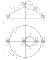
図2に示すように、ブーツ9は、外側継手部材2とシャフト6の中心軸線を含む軸方向平面を対称面とした対称形状である。そして、ブーツ9は、シャフト6の中心軸線に沿って2つに分割されており、本実施形態では、外側継手部材2とシャフト6の中心軸線を含む軸方向平面で2つに分割されている。ブーツ9の分割された2つの部分を、それぞれブーツ片9dと以下記載する。各ブーツ片9dの大径端部9aにおける周方向の両端部には外径側に突出した大径側取付部9eが設けられており、各ブーツ片9dの小径端部9bにおける周方向の両端部には外径側に突出した小径側取付部9fが設けられている。2つのブーツ片9dについて、一方の大径側取付部9e、小径側取付部9fのそれぞれを、他方の大径側取付部9e、小径側取付部9fに例えばボルト9gとナット9hで締結することにより、ブーツ9は環状体11の外周面と、軸受8の外周面に適度に締め付けられて固定される。ブーツ9を取り付けた後には、外側継手部材2とシャフト6の角度や相互の距離は変更できないため、外側継手部材2とシャフト6とが産業機械等に組み付けられた後に、ブーツ9は取り付けられる。
As shown in FIG. 2, the
ブーツ片9dの周方向端面(ブーツ9の分割部分)には、予め或いは取り付け後に、例えば液状パッキンを塗布してもよい。この液状パッキンが固化すれば、ブーツのシール性が向上する。
For example, liquid packing may be applied to the circumferential end surface of the
このように、本実施形態では、ブーツ9が、外側継手部材2とシャフト6のそれぞれに対して軸受7,8を介して相対回転自在に取り付けられている。また、外側継手部材2とシャフト6は作動角αを有する。そして、ブーツ9は、その全部が金属製であり、剛性を有する。ブーツ9の剛性により、作動角αを取った外側継手部材2とシャフト6に取り付けられた状態でのブーツ9の形状が維持される。つまり、ブーツ9の剛性は、ブーツ9の形状を維持するブーツ形状維持手段である。このブーツ形状維持手段によってブーツ9の形状が維持されるため、外側継手部材2とシャフト6が回転した場合、ブーツ9がこれらと共に回転しようとしても、ブーツ9の回転は抑制される。そして、ブーツ形状維持手段がブーツ9に設けられているので、ブーツ9の共回りの抑制に必要な部品点数を抑制でき、また、ブーツ9の共回りの抑制に必要なスペースを抑制できる。
Thus, in this embodiment, the
また、ブーツ9は、剛性があり、形状を剛性により維持し易いので、コンパクト化しても、外側継手部材2やシャフト6に干渉する可能性がほとんどない。従って、ブーツ9のコンパクト化が可能で、これにより、継手内部に充填する潤滑剤の量を減少させることができる。また、ブーツ9は、剛性があるので、スケール等の飛散物が存在する雰囲気で使用しても、損傷等の発生が抑制される。
Moreover, since the
また、軸受7とブーツ9の間に、弾性部材から成る環状体11が配設されているため、ブーツ9の形状と、外側継手部材2とシャフト6との作動角αとの誤差等が、環状体11によって吸収することができる。従って、ブーツ9の形状精度を向上させる必要が無く製造コストの上昇を抑制することができる。
Further, since the
図3は、本発明の第2実施形態に係る等速自在継手を示す軸方向断面図である。以下、第2実施形態に係る等速自在継手について、第1実施形態と異なる点を中心として述べる。本実施形態では、軸受7と軸受8は共に、内輪を有さないシール付き針状ころ軸受である。軸受8の外周面にも、環状体11と同様にゴム等の弾性部材からなる環状体12が圧入されており、その外周面にブーツ9の小径端部9bが固定されている。
FIG. 3 is an axial sectional view showing a constant velocity universal joint according to a second embodiment of the present invention. Hereinafter, the constant velocity universal joint according to the second embodiment will be described focusing on differences from the first embodiment. In this embodiment, both the
外側継手部材2には、軸受7をカバーするダストカバー13が設けられており、シャフト6には、軸受8をカバーするダストカバー14が設けられている。このダストカバー13,14は、軸受7,8を介しての継手内部への異物の浸入を抑制し、軸受7,8を介しての継手内部からの潤滑剤の漏洩を抑制する。
The outer
ダストカバー13,14は断面L状の環状で、筒部13a,14aとつば部13b,14bを有する。ダストカバー13の筒部13aは、外側継手部材2の外周面に圧入され、ダストカバー14の筒部14aは、シャフト6の外周面に圧入される。つば部13bが、環状体11との干渉を防ぐために、環状体11の軸方向端部に対して軸方向に隙間を有して配設され、つば部14bが、環状体12との干渉を防ぐために、環状体12の軸方向端部に対して軸方向に隙間を有して配設される。これらの軸方向隙間は、例えば0.5〜2.0mmが好ましい。0.5mm未満だと、外側継手部材2とシャフト6の回転時に、ダストカバー13,14と環状体11,12が干渉し、回転を妨げる恐れがあり、2.0mmを超えると、異物の浸入の抑制や潤滑剤の漏洩を抑制する効果が十分に得られないからである。
The dust covers 13 and 14 have an annular shape with an L-shaped cross section, and have
図示例では、軸受7,8に対して、ダストカバー13,14は、等速自在継手1の外部側に配設されているが、等速自在継手1の内部側に配設されてもよい。その他の構成と効果は、第1実施形態と同様なので、同一の構成には同一の符号を付し、説明を省略する。
In the illustrated example, the dust covers 13 and 14 are disposed on the outer side of the constant velocity
図4は、本発明の第3実施形態に係る等速自在継手を示す軸方向断面図である。以下、第3実施形態に係る等速自在継手について、第1実施形態と異なる点を中心として述べる。ブーツ15は、例えば軽金属等の金属板から成る大径部16と、例えばクロロプレンゴム等のゴムから成る小径部17とから構成される。また、間座10は存在せず、軸受7は、外側継手部材2の外周面に直接圧入される。
FIG. 4 is an axial sectional view showing a constant velocity universal joint according to a third embodiment of the present invention. Hereinafter, the constant velocity universal joint according to the third embodiment will be described focusing on differences from the first embodiment. The
大径部16は、軸受7の外周面に取り付けられる大径端部16aと、シャフト6の外周面に平行に配設される円筒部16bと、大径端部16aから円筒部16bに向かって漸次縮径する縮径部16cとを備える。また、大径部16は、分割された部材ではなく、一体の部材である。小径部17は、シャフト6に圧入された軸受8の外周面に取り付けられる小径端部17aと、大径部16の円筒部16bの外周面に取り付けられる円筒部17bと、小径端部17aから円筒部17bに向かって漸次拡径する拡径部17cとを備える。なお、小径部17は角度付きブーツではない。
The large-
大径部16の大径端部16aは軸受7の外周面に圧入され、ブーツバンド18aで締め付けられ固定される。小径部17の小径端部17aは、軸受8の外周面に圧入され、ブーツバンド18bで締め付けられ固定される。小径部17の円筒部17bは、大径部16の円筒部16bの外周面に嵌合され、ブーツバンド18cで締め付けられ固定される。なお、本実施形態では、軸受7の外周面に環状体11は存在しない。
The large-
このように、本実施形態では、ブーツ15の小径部17がゴム製なので、柔軟性を有する。このため、環状体11が無くても、ブーツ15の形状と、外側継手部材2とシャフト6との作動角αとの誤差等が、小径部17によって吸収することができる。また、等速自在継手1は、ブーツ15が取り付けられた状態でも、多少作動角αを変化させることができるので、等速自在継手1は、ブーツ15が取り付けられた状態で、産業機械等に組付けることが可能である。従って、等速自在継手1は、ブーツ15が取り付けられた状態で流通させることができる。
Thus, in this embodiment, since the
作動角αを取った外側継手部材2とシャフト6に取り付けられた状態(図4の状態)でのブーツ15の小径部17の形状は、自然状態での小径部17の形状に則している。これにより、小径部17が少しでも変形した場合には、小径部17に図4の状態での形状を維持しようとする弾性復元力が作用する。このことと大径部16の剛性により、作動角αを取った外側継手部材2とシャフト6に取り付けられた状態でのブーツ15の形状が維持される。つまり、大径部16の剛性と小径部17の弾性復元力は、ブーツ15の形状を維持するブーツ形状維持手段である。このブーツ形状維持手段によってブーツ15の形状が維持されるため、外側継手部材2とシャフト6が回転した場合、ブーツ15がこれらと共に回転しようとしても、ブーツ15の回転は抑制される。そして、ブーツ形状維持手段がブーツ15に設けられているので、ブーツ15の共回りの抑制に必要な部品点数を抑制でき、また、ブーツ15の共回りの抑制に必要なスペースを抑制できる。
The shape of the small-
その他の構成と効果は、第1実施形態と同様なので、同一の構成には同一の符号を付し、説明を省略する。 Since other configurations and effects are the same as those of the first embodiment, the same components are denoted by the same reference numerals and description thereof is omitted.
図5は、本発明の第4実施形態に係る等速自在継手を示す軸方向断面図である。以下、第4実施形態に係る等速自在継手について、第3実施形態と異なる点を中心として述べる。ブーツ15の大径部16は、外側継手部材2に圧入された間座10に圧入された軸受7の外周面に取り付けられる大径端部としての円筒部16dと、円筒部16dの軸方向一端を閉塞する底部16eとを有する有底円筒状である。大径部16の底部16eには、貫通孔16fが形成されている。この貫通孔16fは、シャフト6との干渉を回避するため、底部16eにおいて、円筒部16dあるいは外側継手部材2の中心軸線に対して、シャフト6が傾斜している側(図5の下側)に片寄った位置に形成されている。本実施形態では、貫通孔16fは円形状であり、その中心と円筒部16dあるいは外側継手部材2の中心軸線との距離dは、シャフト6の直径や作動角α等を勘案して適宜設定される。
FIG. 5 is an axial sectional view showing a constant velocity universal joint according to a fourth embodiment of the present invention. Hereinafter, the constant velocity universal joint according to the fourth embodiment will be described focusing on differences from the third embodiment. The large-
ブーツ15の小径部17は、シャフト6に圧入された軸受8の外周面に取り付けられる小径端部17dと、小径端部17dと大径部16の底部16eの間に配設される蛇腹状の蛇腹部17eとを備える。小径部17の蛇腹部17eにおける大径部16側の端部は、大径部16の底部16eにおける貫通孔16fの側面に、例えば焼付け等により接続されている。本実施形態では、大径部16の貫通孔16fと、小径部17の蛇腹部17eにおける大径部16側の端部とが円形であるが、これに限定されること無く、楕円等他の形状であってもよい。また、小径部17の蛇腹部17eにおける大径部16側の端部は、小径端部17dより直径が少し大きい。
The small-
大径部16の円筒部16dの開口端部は、軸受7の外周面に圧入され、ブーツバンド18aで締め付けられ固定される。小径部17の小径端部17dは、軸受8の外周面に嵌合され、ブーツバンド18bで締め付けられて固定される。
The open end of the
ブーツ15の小径部17は角度付きブーツであり、作動角αを取った外側継手部材2とシャフト6に取り付けられた状態(図5の状態)でのブーツ15の小径部17の形状は、自然状態の小径部17の形状に則している。これによって、小径部17が少しでも変形した場合には、小径部17に図5の状態の形状を維持しようとする弾性復元力が作用する。このことと大径部16の剛性により、作動角αを取った外側継手部材2とシャフト6に取り付けられた状態でのブーツ15の形状が維持される。つまり、第3実施形態と同様に、大径部16の剛性と小径部17の弾性復元力は、ブーツ15の形状を維持するブーツ形状維持手段である。このブーツ形状維持手段によってブーツ15の形状が維持されるため、外側継手部材2とシャフト6が回転した場合、ブーツ15がこれらと共に回転しようとしても、ブーツ15の回転は抑制される。そして、ブーツ形状維持手段がブーツ15に設けられているので、ブーツ15の共回りの抑制に必要な部品点数を抑制でき、また、ブーツ15の共回りの抑制に必要なスペースを抑制できる。本実施形態では、第3実施形態に比較して、小径部17がブーツ15全体に占める割合が大きく、ブーツ15の形状維持は、小径部17の図5の形状を維持する弾性復元力によるところが大きい。
The small-
このように、本実施形態では、大径部16が有底円筒形状であるので、第3実施形態の大径部16より形成し易いため、製造コストを削減できる。また、小径部17がゴム製で蛇腹部17eを有し、この蛇腹部17eが拡径部17c(図4参照)に比較して長いので、第3実施形態の小径部17より小径部17全体の柔軟性が高い。従って、第3実施形態で上述した小径部17の柔軟性に起因した効果を更に得ることができる。その他の構成と効果は、第3実施形態と同様なので、同一の構成には同一の符号を付し、説明を省略する。
Thus, in this embodiment, since the
図6は、本発明の第5実施形態に係る等速自在継手を示す軸方向断面図である。以下、第5実施形態に係る等速自在継手について、第3実施形態と異なる点を中心として述べる。外側継手部材2に圧入された軸受7は、内輪を有さないシール付き針状ころ軸受である。シャフト6に圧入された軸受8は、1つの深溝玉軸受である。
FIG. 6 is an axial sectional view showing a constant velocity universal joint according to a fifth embodiment of the present invention. Hereinafter, the constant velocity universal joint according to the fifth embodiment will be described focusing on differences from the third embodiment. The
ブーツ19は、全体がクロロプレンゴム等のゴムから構成される。ブーツ19は、軸受7の外周面に取り付けられる大径端部19aと、軸受8の外周面に取り付けられる小径端部19bと、大径端部19aと小径端部19bの間を連結する蛇腹状の蛇腹部19cを備える。ブーツ19の大径端部19aは、軸受7の外周面に嵌合され、ブーツバンド18aで締め付けられ固定される。ブーツ19の小径端部19bは、軸受8の外周面に嵌合され、ブーツバンド18bで締め付けられ固定される。
The
ブーツ19は角度付きブーツであり、作動角αを取った外側継手部材2とシャフト6に取り付けられた状態(図6の状態)でのブーツ19の形状は、自然状態のブーツ19の形状に則している。これによって、ブーツ19が少しでも変形した場合には、ブーツ19に図6での状態での形状を維持しようとする弾性復元力が作用する。この弾性復元力により、作動角αを取った外側継手部材2とシャフト6に取り付けられた状態(図6の状態)でのブーツ19の形状が維持される。つまり、ブーツ19の弾性復元力は、ブーツ19の形状を維持するブーツ形状維持手段である。ブーツ形状維持手段によってブーツ19の形状が維持されるため、外側継手部材2とシャフト6が回転した場合、ブーツ19がこれらと共に回転しようとしても、ブーツ19の回転は抑制される。そして、ブーツ形状維持手段がブーツ19に設けられているので、ブーツ19の共回りの抑制に必要な部品点数を抑制でき、また、ブーツ19の共回りの抑制に必要なスペースを抑制できる。
The
本実施形態では、ブーツ19全体がゴム製で蛇腹部を有するので、ブーツ19全体の柔軟性が高い。このため、ブーツ19の形状と、外側継手部材2とシャフト6との作動角αとの誤差等が、ブーツ19自体によって吸収することができる。また、等速自在継手1は、ブーツ19が取り付けられた状態でも、作動角αを大きく変化させることができるので、等速自在継手1は、ブーツ19が取り付けられた状態で、産業機械等に組付けることが可能である。従って、等速自在継手1を、ブーツ19が取り付けられた状態で流通させることができる。その他の構成と効果は、第3実施形態と同様なので、同一の構成には同一の符号を付し、説明を省略する。
In the present embodiment, since the
図7は、本発明の第6実施形態に係る等速自在継手を示す軸方向断面図である。以下、第6実施形態に係る等速自在継手について、第5実施形態と異なる点を中心として述べる。 FIG. 7 is an axial sectional view showing a constant velocity universal joint according to a sixth embodiment of the present invention. Hereinafter, the constant velocity universal joint according to the sixth embodiment will be described focusing on differences from the fifth embodiment.
本実施形態のブーツ19の全体はクロロプレンゴム等のゴムから構成されるが、第5実施形態と異なり、ブーツ19は角度付きブーツではない。すなわち、ブーツ19は、従来のブーツ36(図10参照)と同様である。ブーツ19の大径端部19aは、軸受7の外周面に嵌合され、ブーツバンド20で締め付けられ固定される。ブーツ19の小径端部19bは、軸受8の外周面に嵌合され、ブーツバンド21で締め付けられ固定される。
The
ブーツバンド20,21は、それぞれの周方向で、作動角αを取った外側継手部材2とシャフト6が接近する側(図7で下側)の位置に、外径側に突出する突出部20a,21aが形成されている。突出部20a,21aのそれぞれには、スリット(図示省略)が設けられており、これに連結部材としての例えばひも22等を結びつけることで突出部20a,21aを相互に連結する。このひも22等の張力によって、作動角αを取った外側継手部材2とシャフト6に取り付けられた状態(図7の状態)でのブーツ19の形状が維持される。つまり、連結部材としてのひも22等の張力は、ブーツ19の形状を維持するブーツ形状維持手段である。このブーツ形状維持手段によってブーツ19の形状が維持されるため、外側継手部材2とシャフト6が回転した場合、ブーツ19がこれらと共に回転しようとしても、ブーツ19の回転は抑制される。そして、ブーツ形状維持手段がブーツ19に設けられているので、ブーツ19の共回りの抑制に必要な部品点数を抑制でき、また、ブーツ19の共回りの抑制に必要なスペースを抑制できる。
The
本実施形態では、第5実施形態と同様に、ブーツ19全体がゴム製で蛇腹部19cを有するので、ブーツ19全体の柔軟性が高い。従って、第5実施形態で説明したものと同様の効果が享受できる。
In the present embodiment, as in the fifth embodiment, since the
また、本実施形態では、ブーツ19は従来のブーツ36を使用可能なので、ブーツ製造のための設備を更新する必要が無く、製造コストを抑制できる。
Moreover, in this embodiment, since the
本実施形態では、ブーツ19の大径端部19a、小径端部19bを、それぞれに取り付けたブーツバンド20,21を介して連結部材としてのひも22で連結したが、本発明はこれに限定されず、ブーツ19の軸方向で位置が異なるブーツ19本体の部位を直接連結部材で連結してもよい。
In the present embodiment, the large-
その他の構成と効果は、第5実施形態と同様なので、同一の構成には同一の符号を付し、説明を省略する。 Since other configurations and effects are the same as those of the fifth embodiment, the same components are denoted by the same reference numerals and description thereof is omitted.
図8は、本発明の参考例に係る等速自在継手を示す軸方向断面図である。以下、参考例に係る等速自在継手について、第5実施形態と異なる点を中心として述べる。 FIG. 8 is an axial sectional view showing a constant velocity universal joint according to a reference example of the present invention. Hereinafter, the constant velocity universal joint according to the reference example will be described focusing on differences from the fifth embodiment.
本参考例のブーツ19は、第6実施形態と同様で従来のブーツ36と同様である。ブーツ19の大径端部19aは、軸受7の外周面に嵌合され、ブーツバンド18aで締め付けられ固定される。ブーツ19の小径端部19bは、軸受8の外周面に嵌合され、ブーツバンド18bで締め付けられ固定される。
The
ブーツ19における蛇腹部19cの谷部における最小径部位の外周には、リング23が嵌合されている。リング23は例えば接着剤等によってブーツ19に固定されている。図9に拡大して示すように、リング23は、その半分23aが密度の大きいもの、例えば鉄等の金属、そして残りの半分23bが密度の小さいもの、例えばゴム等で構成されており、これらは例えば焼付け等によって接続されている。この構成により、このリング23は、密度の大きい半分23aの側に、重心が偏っている。ブーツ19に嵌合された複数のリング23は、リング23における重心が偏った側が、ブーツ19の周方向で同じ方向となっている。これにより、ブーツ19が周方向に少しでも回転した場合に、リング23における重心が偏った側が常に下側になるようにリング23を介してブーツ19に重力が作用する。
A
図示例では、理解し易いように、外側継手部材2とシャフト6は作動角αを取っていないが、作動角αを取った場合でも、ブーツ19が周方向に少しでも回転した場合に、リング23における重心が偏った側が常に下側になるようにリング23を介してブーツ19に重力が作用する。このため、外側継手部材2とシャフト6が回転した場合、ブーツ19がこれらと共に回転しようとしても、ブーツ19の回転は抑制される。そして、ブーツ形状維持手段がブーツ19に設けられているので、ブーツ19の共回りの抑制に必要な部品点数を抑制でき、また、ブーツ19の共回りの抑制に必要なスペースを抑制できる。
In the illustrated example, for easy understanding, the outer
このように本参考例でも、第5実施形態と同様に、ブーツ19全体がゴム製で蛇腹部19cを有するので、ブーツ19全体の柔軟性が高い。従って、第5実施形態で説明したものと同様の効果が享受できる。
Thus, also in the present reference example , as in the fifth embodiment, the
本参考例でも、ブーツ19は従来のブーツ36を使用可能なので、ブーツ製造のための設備を更新する必要が無く、製造コストを抑制できる。
Also in this reference example , since the
また、本参考例で、リング23の半分23bがゴム等の弾性部材であれば、リング23を蛇腹部19cの谷部における最小径部位の外周に嵌合させるために、蛇腹部の19cの山部を通過させることが容易になり、生産効率を向上できる。
Further, in this reference example , if the half 23b of the
本参考例では、ブーツ19の回転の抑制に、ブーツ19に外嵌したリング23の重心の偏りを利用したが、本発明はこれに限定されず、厚さを周方向で異ならせる等の方法によってブーツ19自体が有する重心の偏りを利用してもよい。
In the present reference example , the bias of the center of gravity of the
その他の構成と効果は、第5実施形態と同様なので、同一の構成には同一の符号を付し、説明を省略する。 Since other configurations and effects are the same as those of the fifth embodiment, the same components are denoted by the same reference numerals and description thereof is omitted.
上記実施形態におけるブーツ15,19のゴム製部位は、熱可塑性エラストマー等の樹脂で構成してもよく、特に熱可塑性ポリエステル系エラストマーで構成した場合には、耐疲労性、耐摩耗性、耐熱老化性等が向上する。
The rubber parts of the
外側継手部材2やシャフト6に圧入された軸受7,8は、上記実施形態に限定されず、円筒ころ軸受等他の転がり軸受でもよく、また、滑り軸受等の別形式の軸受であってもよい。
The
また、上記実施形態では、等速自在継手1として、ツェッパ型の固定式等速自在継手を使用したが、本発明はこれに限定されず、アンダーカットフリー型等別の固定式等速自在継手を使用してもよく、また、ダブルオフセット型、トリポード型、クロスグルーブ型等の摺動式等速自在継手を使用してもよい。
Further, in the above embodiment, the fixed constant velocity universal joint of the Zepper type is used as the constant velocity
1 等速自在継手
2 外側継手部材
3 内側継手部材
4 ボール(トルク伝達部材)
6 シャフト
7,8 軸受
9,15,19 ブーツ
9a,16a,16d,19a 大径端部
9b,17a,17d,19b 小径端部
9c,16c 縮径部
11,12 環状体
13,14 ダストカバー
16 大径部
17 小径部
22 ひも(連結部材)
α 作動角
1 constant velocity
6
α Working angle
Claims (10)
前記ブーツの全体が、前記等速自在継手以外の非回転部材に固定されておらず、
前記外側継手部材と前記シャフトとが作動角を取った状態での前記ブーツの形状を維持するブーツ形状維持手段が前記ブーツに設けられ、
前記ブーツ形状維持手段によって前記外側継手部材と前記シャフトとが前記作動角を取った状態での前記ブーツの形状が維持されるため、前記外側継手部材と前記シャフトとが前記作動角を取って回転した場合に、前記ブーツが前記外側継手部材と前記シャフトと共回りすることを抑制可能であることを特徴とする等速自在継手。 An outer joint member, an inner joint member, a torque transmission member for transmitting torque between the outer joint member and the inner joint member, a shaft connected to the inner joint member, and each of the outer joint member and the shaft In a constant velocity universal joint provided with a large diameter end portion and a boot having a small diameter end portion that are attached to each other in a relatively rotatable manner via a bearing,
The entire boot is not fixed to a non-rotating member other than the constant velocity universal joint,
Boot shape maintaining means for maintaining the shape of the boot in a state where the outer joint member and the shaft take an operating angle is provided in the boot,
The boot shape maintaining means maintains the shape of the boot in a state in which the outer joint member and the shaft take the operating angle, so that the outer joint member and the shaft rotate by taking the operating angle. In this case, it is possible to suppress the boot from rotating together with the outer joint member and the shaft.
前記ブーツ形状維持手段が、前記ブーツの金属の剛性である請求項1に記載の等速自在継手。 All of the boots are made of metal;
The constant velocity universal joint according to claim 1, wherein the boot shape maintaining means is a metal rigidity of the boot.
前記ブーツ形状維持手段が、前記大径部の金属の剛性と、前記小径部のゴム又は樹脂の弾性復元力である請求項1に記載の等速自在継手。 The boot is composed of a metal large diameter portion including the large diameter end portion, and a rubber or resin small diameter portion including the small diameter end portion,
2. The constant velocity universal joint according to claim 1, wherein the boot shape maintaining means is rigidity of the metal of the large diameter portion and elastic restoring force of rubber or resin of the small diameter portion.
前記ブーツ形状維持手段が、前記角度付きブーツの弾性復元力である請求項1に記載の等速自在継手。 All of the boots are composed of angled boots,
The constant velocity universal joint according to claim 1, wherein the boot shape maintaining means is an elastic restoring force of the angled boot.
前記ブーツ形状維持手段が、前記ブーツの軸方向で位置が異なる部位を直接的又は間接的に連結した連結部材の張力である請求項1に記載の等速自在継手。 All of the boots are made of rubber or resin,
2. The constant velocity universal joint according to claim 1, wherein the boot shape maintaining means is a tension of a connecting member that directly or indirectly connects portions having different positions in the axial direction of the boot.
Priority Applications (1)
| Application Number | Priority Date | Filing Date | Title |
|---|---|---|---|
| JP2011205984A JP5868643B2 (en) | 2011-09-21 | 2011-09-21 | Constant velocity universal joint |
Applications Claiming Priority (1)
| Application Number | Priority Date | Filing Date | Title |
|---|---|---|---|
| JP2011205984A JP5868643B2 (en) | 2011-09-21 | 2011-09-21 | Constant velocity universal joint |
Publications (2)
| Publication Number | Publication Date |
|---|---|
| JP2013068245A JP2013068245A (en) | 2013-04-18 |
| JP5868643B2 true JP5868643B2 (en) | 2016-02-24 |
Family
ID=48474170
Family Applications (1)
| Application Number | Title | Priority Date | Filing Date |
|---|---|---|---|
| JP2011205984A Expired - Fee Related JP5868643B2 (en) | 2011-09-21 | 2011-09-21 | Constant velocity universal joint |
Country Status (1)
| Country | Link |
|---|---|
| JP (1) | JP5868643B2 (en) |
Cited By (5)
| Publication number | Priority date | Publication date | Assignee | Title |
|---|---|---|---|---|
| KR20220144075A (en) | 2021-04-19 | 2022-10-26 | 현대위아 주식회사 | Drive axle assembly |
| KR20220166522A (en) | 2021-06-10 | 2022-12-19 | 현대위아 주식회사 | Corner module of drive axle |
| KR20220166521A (en) | 2021-06-10 | 2022-12-19 | 현대위아 주식회사 | Boot assembly of drive axle |
| KR20230052005A (en) | 2021-10-12 | 2023-04-19 | 현대자동차주식회사 | Drive axle assembly |
| KR20230055729A (en) | 2021-10-19 | 2023-04-26 | 현대위아 주식회사 | Drive axle assembly |
Families Citing this family (1)
| Publication number | Priority date | Publication date | Assignee | Title |
|---|---|---|---|---|
| JP2017026004A (en) * | 2015-07-21 | 2017-02-02 | Ntn株式会社 | Propeller shaft fastening structure |
Family Cites Families (11)
| Publication number | Priority date | Publication date | Assignee | Title |
|---|---|---|---|---|
| GB776888A (en) * | 1954-03-29 | 1957-06-12 | Walterscheid Gmbh Jean | A protective device for universal joint shafts coupling a driving and a driven member |
| JPS5359051U (en) * | 1976-10-21 | 1978-05-19 | ||
| JPS5364867U (en) * | 1976-10-29 | 1978-05-31 | ||
| DE3422855C1 (en) * | 1984-06-20 | 1985-11-14 | Gerhard 8221 Bergen Hoffmann | Housing for a bendable articulated connection between two shaft ends |
| JPS62102724U (en) * | 1985-12-20 | 1987-06-30 | ||
| JPH0519667U (en) * | 1991-08-30 | 1993-03-12 | 株式会社小松製作所 | Constant velocity joint boot device |
| JPH1113783A (en) * | 1997-06-30 | 1999-01-22 | Nippon Seiko Kk | Bearing device for wheel |
| JP3838465B2 (en) * | 1998-01-12 | 2006-10-25 | 株式会社ショーワ | Dust cover assembly structure of bevel gear device |
| JP3546000B2 (en) * | 2000-07-14 | 2004-07-21 | 丸五ゴム工業株式会社 | Steering joint cover |
| DE112004002218T5 (en) * | 2003-11-18 | 2006-10-19 | GKN Driveline North America, Inc., Auburn Hills | Torque transmission device with a constant velocity joint output |
| DE102005011257B4 (en) * | 2005-03-11 | 2009-03-26 | Audi Ag | Steering device for motor vehicles |
-
2011
- 2011-09-21 JP JP2011205984A patent/JP5868643B2/en not_active Expired - Fee Related
Cited By (6)
| Publication number | Priority date | Publication date | Assignee | Title |
|---|---|---|---|---|
| KR20220144075A (en) | 2021-04-19 | 2022-10-26 | 현대위아 주식회사 | Drive axle assembly |
| KR20220166522A (en) | 2021-06-10 | 2022-12-19 | 현대위아 주식회사 | Corner module of drive axle |
| KR20220166521A (en) | 2021-06-10 | 2022-12-19 | 현대위아 주식회사 | Boot assembly of drive axle |
| DE112022002999T5 (en) | 2021-06-10 | 2024-04-11 | Hyundai Wia Corporation | Drive axle bellows assembly |
| KR20230052005A (en) | 2021-10-12 | 2023-04-19 | 현대자동차주식회사 | Drive axle assembly |
| KR20230055729A (en) | 2021-10-19 | 2023-04-26 | 현대위아 주식회사 | Drive axle assembly |
Also Published As
| Publication number | Publication date |
|---|---|
| JP2013068245A (en) | 2013-04-18 |
Similar Documents
| Publication | Publication Date | Title |
|---|---|---|
| JP5868643B2 (en) | Constant velocity universal joint | |
| JP5606972B2 (en) | Slewing bearing seal structure and slewing bearing | |
| US10520036B2 (en) | Sealing device | |
| JP6050080B2 (en) | Sealed rolling bearing | |
| US20070284829A1 (en) | Sealing Device | |
| JP2018059586A (en) | Bearing seal device | |
| WO2011013551A1 (en) | Seal structure of slewing bearing and slewing support apparatus | |
| JP2014119029A (en) | Rolling bearing | |
| KR20100064081A (en) | Boot mounting structure | |
| JP2013002587A (en) | Constant velocity universal joint | |
| WO2016136355A1 (en) | Constant velocity universal joint | |
| WO2012128103A1 (en) | Seal structure for slewing bearing, and slewing bearing | |
| WO2017014005A1 (en) | Propeller shaft fastening structure | |
| JP2012041969A (en) | Boot for constant velocity universal joint and constant velocity universal joint | |
| JP6305744B2 (en) | Constant velocity universal joint | |
| US10533655B2 (en) | One-way clutch | |
| JP2017053446A (en) | Boot for constant velocity universal joint | |
| RU181829U1 (en) | Vehicle hub assembly | |
| JP2008025644A (en) | Bearing device for wheel | |
| JP2008144810A (en) | Boot | |
| JP4600814B2 (en) | Bearing seal | |
| JP7273963B2 (en) | Sealing device, sealing structure and method of fixing sealing structure | |
| JP4975341B2 (en) | Mounting structure for constant velocity universal joint boots | |
| WO2023204201A1 (en) | Sealing structure | |
| JP2023020379A (en) | constant velocity universal joint |
Legal Events
| Date | Code | Title | Description |
|---|---|---|---|
| A621 | Written request for application examination |
Free format text: JAPANESE INTERMEDIATE CODE: A621 Effective date: 20140221 |
|
| A131 | Notification of reasons for refusal |
Free format text: JAPANESE INTERMEDIATE CODE: A131 Effective date: 20141014 |
|
| A977 | Report on retrieval |
Free format text: JAPANESE INTERMEDIATE CODE: A971007 Effective date: 20141016 |
|
| A521 | Request for written amendment filed |
Free format text: JAPANESE INTERMEDIATE CODE: A523 Effective date: 20141210 |
|
| A131 | Notification of reasons for refusal |
Free format text: JAPANESE INTERMEDIATE CODE: A131 Effective date: 20150622 |
|
| A521 | Request for written amendment filed |
Free format text: JAPANESE INTERMEDIATE CODE: A523 Effective date: 20150820 |
|
| TRDD | Decision of grant or rejection written | ||
| A01 | Written decision to grant a patent or to grant a registration (utility model) |
Free format text: JAPANESE INTERMEDIATE CODE: A01 Effective date: 20151216 |
|
| A61 | First payment of annual fees (during grant procedure) |
Free format text: JAPANESE INTERMEDIATE CODE: A61 Effective date: 20160106 |
|
| R150 | Certificate of patent or registration of utility model |
Ref document number: 5868643 Country of ref document: JP Free format text: JAPANESE INTERMEDIATE CODE: R150 |
|
| LAPS | Cancellation because of no payment of annual fees |