WO2012128062A1 - Sealing device - Google Patents
Sealing device Download PDFInfo
- Publication number
- WO2012128062A1 WO2012128062A1 PCT/JP2012/056059 JP2012056059W WO2012128062A1 WO 2012128062 A1 WO2012128062 A1 WO 2012128062A1 JP 2012056059 W JP2012056059 W JP 2012056059W WO 2012128062 A1 WO2012128062 A1 WO 2012128062A1
- Authority
- WO
- WIPO (PCT)
- Prior art keywords
- floating ring
- rotating shaft
- sealing device
- dynamic pressure
- peripheral surface
- Prior art date
Links
Images


Classifications
-
- F—MECHANICAL ENGINEERING; LIGHTING; HEATING; WEAPONS; BLASTING
- F16—ENGINEERING ELEMENTS AND UNITS; GENERAL MEASURES FOR PRODUCING AND MAINTAINING EFFECTIVE FUNCTIONING OF MACHINES OR INSTALLATIONS; THERMAL INSULATION IN GENERAL
- F16J—PISTONS; CYLINDERS; SEALINGS
- F16J15/00—Sealings
- F16J15/44—Free-space packings
- F16J15/441—Free-space packings with floating ring
Definitions
- the present invention relates to a sealing device used for a rotating shaft, and particularly to a sealing device provided with a floating ring used for a rotating shaft such as a pump.
- Prior Art 1 As a sealing device provided with a floating ring, for example, the one shown in FIG. 6 is known (hereinafter referred to as “Prior Art 1”, for example, see Patent Document 1).
- This prior art 1 has at least one circumferential groove and a plurality of linear grooves extending from the circumferential groove toward the outer circumferential surface on the low-pressure side surface of the floating ring 30 that comes into contact with the locking ring 32 provided on the casing.
- the pressure balance groove 33 that guides the high-pressure fluid, a wedge effect (generated in the wedge portion) generated in a small gap formed between the inner peripheral surface of the floating ring 30 and the rotary shaft 31 is provided.
- the gap between the inner peripheral surface of the floating ring 30 and the rotating shaft 31 is kept constant, and the inner peripheral surface of the floating ring 30 and the rotating shaft 31 that moves are in contact with each other.
- Rukoto is that to prevent leakage of growth and shutdown of equipment to the low pressure side of the high pressure fluid.
- FIG. 7 As another sealing device provided with a floating ring, the one shown in FIG. 7 is known (hereinafter referred to as “Prior Art 2”, for example, see Patent Document 2).
- This conventional technique 2 On the outer periphery of the floating ring 35 formed in an annular shape, a radially outwardly connecting portion 36 is provided, and a pair of the connecting portions 36 are provided at intervals of 180 degrees in the circumferential direction.
- the floating ring 35 is inserted into the groove portion 38 to support the rotating shaft 39 concentrically.
- the sealing device provided with the floating ring of the prior art 1 when the dynamic pressure generated in the portion where the gap between the inner peripheral surface of the floating ring 30 and the rotating shaft 31 is smaller than the weight of the floating ring 30, The gap formed between the inner peripheral surface of the floating ring 30 and the rotating shaft 31 is not uniform, but is operated in an eccentric state. Further, in the sealing device having the floating ring of the prior art 2 shown in FIG. 7, a pair of connecting portions 36 provided at intervals of 180 degrees in the circumferential direction are inserted into the groove portion 38 of the casing 37.
- the floating ring 35 is not rotated, since it is practically difficult to assemble the floating ring 35 concentrically with the rotating shaft 39, the floating ring 35 is assembled in an eccentric state with respect to the rotating shaft 39. There was a problem of being. Further, there is a problem that the floating ring 35 cannot flexibly follow the eccentricity of the rotating shaft 39 due to the bending of the rotating shaft 39 or the like.
- the present invention in a sealing device having a floating ring, prevents the rotation of the floating ring and uses the dynamic pressure generated by the dynamic pressure groove provided on the inner peripheral surface of the floating ring, thereby reducing the weight of the floating ring. It is an object of the present invention to provide a sealing device that can match the centers of a floating ring and a rotating shaft even when the lifting force due to the wedge effect between the rotating shaft and the floating ring does not match.
- the sealing device of the present invention is, firstly, in a sealing device provided with a floating ring between the outer periphery of the rotating shaft and the inner periphery of the casing, and a detent means at one place in the circumferential direction of the floating ring. And a groove for generating dynamic pressure is provided on the inner peripheral surface of the floating ring in an uneven manner in the circumferential direction.
- the sealing device of the present invention is secondly characterized in that, in the first feature, when the weight of the floating ring is greater than the force of lifting the floating ring due to the wedge effect between the rotating shaft and the floating ring, In the coordinate system in which the origin of the XY coordinate axis is set at the center of the rotation axis when viewed from the side, when the rotation direction of the rotation axis is counterclockwise, the rotation prevention means is provided at a position in the second and third quadrants; A groove for generating dynamic pressure is provided in the first quadrant of the inner peripheral surface of the floating ring, or in the first quadrant and the second quadrant.
- the rotating shaft when the weight of the floating ring ⁇ the force of lifting the floating ring due to the wedge effect between the rotating shaft and the floating ring, the rotating shaft is In the coordinate system in which the origin of the XY coordinate axis is set at the center of the rotation axis when viewed from the side, when the rotation direction of the rotation axis is counterclockwise, the rotation prevention means is provided at a position in the second and third quadrants; A groove for generating a dynamic pressure is provided at a position of the fourth quadrant or the third quadrant and the fourth quadrant of the inner peripheral surface of the floating ring.
- the present invention has the following excellent effects. (1) In a sealing device provided with a floating ring, while preventing rotation of the floating ring during rotation of the rotating shaft, and utilizing the dynamic pressure generated by the dynamic pressure groove provided on the inner peripheral surface of the floating ring, Even when the weight of the floating ring and the force for lifting the floating ring due to the wedge effect between the rotating shaft and the floating ring do not match, the centers of the floating ring and the rotating shaft can be matched. (2) Since the center of the floating ring and the rotating shaft can be matched during rotation of the rotating shaft, the gap between the inner peripheral surface of the floating ring and the outer peripheral surface of the rotating shaft can be set small. The sealing performance can be improved. Moreover, since the fluid film thickness can be increased to an average, the risk of contact between the inner peripheral surface of the floating ring and the outer peripheral surface of the rotating shaft can be reduced.
- FIG. 1 is a front sectional view schematically showing a sealing device according to an embodiment of the present invention, in which a floating ring is lifted upward by rotation of a rotating shaft.
- a rotary shaft 3 such as a pump is disposed so as to pass through the hole 2 of the casing 1, and the left side is a high pressure side and the right side is a low pressure side.
- a radial gap ⁇ is provided between the inner peripheral surface of the casing 1 and the outer peripheral surface of the rotary shaft 3.
- a hollow cylindrical shape surrounding the outer periphery of the rotary shaft 3 is provided.
- a floating ring 5 is provided.
- a cylindrical space 4 for accommodating the floating ring 5 is provided in the casing 1, and the diameter and width of the space 4 are larger than the outer diameter and width of the floating ring 5. Further, the inner diameter of the floating ring 5 is set to be slightly larger than the outer diameter of the rotating shaft 3, so that the floating ring 5 can move in a certain range in the radial direction.
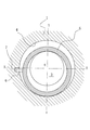
- FIG. 2 is a side view schematically showing the sealing device according to the embodiment of the present invention, and shows a state where the rotating shaft is stationary.
- a locking pin 6 is provided on the left side surface of the outer peripheral surface of the floating ring 5 so as to protrude radially outward.
- the locking pin 6 extends in the radial direction from the cylindrical space 4 of the casing 1. It is loosely fitted in a groove 7 provided on the outer side so as to prevent the floating ring 5 from rotating.
- One stop pin 6 is provided in the circumferential direction of the floating ring 5, and the position thereof is XY coordinates with the center O of the rotating shaft 3 as the origin when the rotating direction of the rotating shaft 3 is counterclockwise.
- the rotation preventing means is not limited to the pin, and the essential point is that it can be locked to the casing 1 and has a function of preventing the floating ring 5 from rotating.
- FIG. 3 is a side view schematically showing the sealing device according to the embodiment of the present invention, and shows a state in which the rotating shaft starts to rotate.
- a force for lifting the floating ring 5 is generated due to the wedge effect in the gap S of the sealed fluid interposed between the rotating shaft 3 and the floating ring 5.
- the center of the floating ring 5 is below the center of the rotating shaft 3.
- the dynamic pressure grooves 8 for generating dynamic pressure are unevenly arranged in the circumferential direction so that the center of the floating ring 5 and the center of the rotating shaft 3 are matched as much as possible.
- FIG. 3 has a relationship of the weight of the floating ring> the force of lifting the floating ring due to the wedge effect between the rotating shaft and the floating ring, and the rotating direction of the rotating shaft 3 is counterclockwise.
- the dynamic pressure groove 8 for generating dynamic pressure is formed in the first quadrant of the inner peripheral surface of the floating ring 5 or the first quadrant.
- the provision of the dynamic pressure grooves in the circumferential direction at non-uniform intervals means that the dynamic pressure grooves are not evenly arranged in the circumferential direction, but locally as shown in FIG. In addition to providing the dynamic pressure groove, it means that the dynamic pressure groove is locally eliminated or the groove depth is locally changed.
- the rotating shaft 3 is viewed from one side surface.
- the anti-rotation means 6 is provided at a position in the second and third quadrants.
- the pressure generating groove 8 is provided at the position of the fourth quadrant or the third and fourth quadrants of the inner peripheral surface of the floating ring 5.
- the weight of the floating ring 5 is W
- the force for lifting the floating ring 5 due to the wedge effect of the clearance S between the rotating shaft 3 and the floating ring 5 is F1
- the dynamic pressure p generated in the dynamic pressure groove 8 is the floating ring.
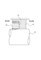
- FIG. 5 is a view showing an example of the dynamic pressure generating groove 8 provided locally on the inner peripheral surface of the floating ring 5.
- the dynamic pressure generating groove 8 is provided on the half surface of the high pressure side so as to communicate with the high pressure side, has a shape inclined along the rotation direction of the rotary shaft 3, and goes to the end portion 9. It is shallow.
- the high-pressure fluid can be easily guided into the dynamic pressure generating groove 8, and the dynamic pressure effect can be exhibited more reliably.
Landscapes
- Engineering & Computer Science (AREA)
- General Engineering & Computer Science (AREA)
- Mechanical Engineering (AREA)
- Sealing Using Fluids, Sealing Without Contact, And Removal Of Oil (AREA)
Abstract
Description
環状に形成されたフローティングリング35の外周には、半径方向外方へ向かう連結部36が設けられ、この連結部36は、円周方向に180度の間隔をおいて一対設けられ、ケーシング37の溝部38に挿入されてフローティングリング35を回転軸39と同心状に支持するものである。 As another sealing device provided with a floating ring, the one shown in FIG. 7 is known (hereinafter referred to as “
On the outer periphery of the
また、図7に示す従来技術2のフローティングリングを備えたシール装置においては、円周方向に180度の間隔をおいて一対設けられた連結部36が、ケーシング37の溝部38に挿入されているため、フローティングリング35が回転されることはないが、回転軸39と同心にフローティングリング35を組立てることが現実的には困難であるため、回転軸39に対してフローティングリング35が偏心状態で組立てられるという問題があった。さらに、回転軸39の撓み等による回転軸39の偏心に対してフローティングリング35が柔軟に追従できないという問題もあった。 However, in the sealing device provided with the floating ring of the
Further, in the sealing device having the floating ring of the
本発明は、フローティングリングを備えたシール装置において、フローティングリングの回転を防止するとともに、フローティングリングの内周面に設けた動圧溝の発生する動圧を利用することにより、フローティングリングの重量と回転軸とフローティングリングとのくさび効果によるフローティングリングを持ち上げる力とが一致しない場合でも、フローティングリングと回転軸との中心を一致させることができるシール装置を提供することを目的とする。 When the center of the floating ring and the rotating shaft cannot be matched as in the above
The present invention, in a sealing device having a floating ring, prevents the rotation of the floating ring and uses the dynamic pressure generated by the dynamic pressure groove provided on the inner peripheral surface of the floating ring, thereby reducing the weight of the floating ring. It is an object of the present invention to provide a sealing device that can match the centers of a floating ring and a rotating shaft even when the lifting force due to the wedge effect between the rotating shaft and the floating ring does not match.
(1)フローティングリングを備えたシール装置において、回転軸の回転中におけるフローティングリングの回転を防止するとともに、フローティングリングの内周面に設けた動圧溝の発生する動圧を利用することにより、フローティングリングの重量と回転軸とフローティングリングとのくさび効果によるフローティングリングを持ち上げる力とが一致しない場合でも、フローティングリングと回転軸との中心を一致させることができる。
(2)回転軸の回転中においてフローティングリングと回転軸の中心を一致させることができるため、フローティングリングの内周面と回転軸の外周面との隙間を小さく設定することができ、シール装置のシール性の向上を図ることができる。また、流体膜厚さを平均に増加させることができるため、フローティングリングの内周面と回転軸の外周面との接触の危険性を低減することができる。 The present invention has the following excellent effects.
(1) In a sealing device provided with a floating ring, while preventing rotation of the floating ring during rotation of the rotating shaft, and utilizing the dynamic pressure generated by the dynamic pressure groove provided on the inner peripheral surface of the floating ring, Even when the weight of the floating ring and the force for lifting the floating ring due to the wedge effect between the rotating shaft and the floating ring do not match, the centers of the floating ring and the rotating shaft can be matched.
(2) Since the center of the floating ring and the rotating shaft can be matched during rotation of the rotating shaft, the gap between the inner peripheral surface of the floating ring and the outer peripheral surface of the rotating shaft can be set small. The sealing performance can be improved. Moreover, since the fluid film thickness can be increased to an average, the risk of contact between the inner peripheral surface of the floating ring and the outer peripheral surface of the rotating shaft can be reduced.
図1において、ケーシング1の孔2内を貫通するようにしてポンプ等の回転軸3が配設されており、左側が高圧側、右側が低圧側である。ケーシング1の内周面と回転軸3の外周面との間には半径方向の隙間δが設けられており、この隙間δをシールするため、回転軸3の外周を囲むように中空円筒状のフローティングリング5が設けられる。また、ケーシング1内には、前記フローティングリング5を収容する円筒状の空間4が設けられ、この空間4の径及び幅は、フローティングリング5の外径及び幅よりも大きい。さらに、フローティングリング5の内径は回転軸3の外径よりもわずかに大きく設定されており、フローティングリング5が半径方向に一定の範囲で移動可能となっている。 FIG. 1 is a front sectional view schematically showing a sealing device according to an embodiment of the present invention, in which a floating ring is lifted upward by rotation of a rotating shaft.
In FIG. 1, a
図2において、フローティングリング5の外周面の左側面には回止ピン6が半径方向外方に突出するように設けられ、該回止ピン6は、ケーシング1の円筒状の空間4から半径方向外方に設けられた溝7内に遊嵌され、フローティングリング5の回転を防止するようになっている。回止ピン6はフローティングリング5の円周方向において1個所設けら、その位置は、回転軸3の回転方向を反時計方向にあるとき、回転軸3の中心Oを原点とするX-Y座標系において、第2及び第3象限に位置しておればよく、特に図2の位置に限定されるものではない。また、回り止め手段としてはピンに限らず、要は、ケーシング1に係止されてフローティングリング5の回転を防止する機能を有するものであればよい。 FIG. 2 is a side view schematically showing the sealing device according to the embodiment of the present invention, and shows a state where the rotating shaft is stationary.
In FIG. 2, a
今、回転軸3が反時計方向に回転を始めると、回転軸3とフローティングリング5との間に介在する被密封流体の隙間Sにおけるくさび効果によりフローティングリング5を持ち上げる力が発生する。このとき、フローティングリングの重量>回転軸3とフローティングリング5とのくさび効果によりフローティングリング5を持ち上げる力、の関係にある場合、フローティングリング5の中心は回転軸3の中心より下方にある。このような状態においては、回転軸外周とフローティング内周との間に介在する流体膜が局所的に薄くなるため、回転軸3の異常振動など不安定な挙動を起こしたときにフローティングリング5の内周面と回転軸3の外周面とが接触する危険がある。このような危険を避けるためには、フローティングリング5の内周面と回転軸3の外周面との隙間を大きく設定する必要がある。しかし、この隙間を大きくすると、この隙間からの被密封流体の漏れ量が隙間の3乗に比例して多くなる。 FIG. 3 is a side view schematically showing the sealing device according to the embodiment of the present invention, and shows a state in which the rotating shaft starts to rotate.
Now, when the rotating
例えば、図3に示すものは、フローティングリングの重量>回転軸とフローティングリングとのくさび効果でフローティングリングを持ち上げる力、の関係にあるものであって、回転軸3の回転方向を反時計方向とした場合、回転軸3の中心にX-Y座標軸の原点をおいた座標系において、動圧を発生させるための動圧溝8を、フローティングリング5の内周面の第1象限、または、第1象限及び第2象限の位置に設けている。
なお、本発明において、動圧溝を円周方向に非等配に設けるとは、動圧溝を円周方向に等分に配設するのではなく、図3に示すように、局所的に動圧溝を設けることの他、動圧溝を局所的になくしたり、局所的に溝深さを変えたりして設けることを意味するものである。 In the present invention, when the
For example, what is shown in FIG. 3 has a relationship of the weight of the floating ring> the force of lifting the floating ring due to the wedge effect between the rotating shaft and the floating ring, and the rotating direction of the
In the present invention, the provision of the dynamic pressure grooves in the circumferential direction at non-uniform intervals means that the dynamic pressure grooves are not evenly arranged in the circumferential direction, but locally as shown in FIG. In addition to providing the dynamic pressure groove, it means that the dynamic pressure groove is locally eliminated or the groove depth is locally changed.
ここで、フローティングリング5の重量をW、回転軸3とフローティングリング5との隙間Sのくさび効果によりフローティングリング5を持ち上げる力をF1、及び、動圧溝8で発生する動圧pによりフローティングリング5を持ち上げる力をF2とし、それぞれの作用点における回止ピン6からのX方向の距離をL1、L2、L3とした場合、
W・L1=F1・L2+F2・L3
となるように動圧溝8で発生する動圧pによる力F2を設定すれば、図4に示すように、フローティングリング5の中心と回転軸3の中心とは一致する。したがって、フローティングリング5の内周面と回転軸3の外周面との隙間を小さく設定することができ、シール装置のシール性を向上させることができる。また、流体膜厚さを平均に増加させることができるため、フローティングリング5の内周面と回転軸3の外周面との接触の危険性を低減することができる。 When the dynamic pressure p as shown in FIG. 3 is generated by the
Here, the weight of the floating
W ・ L1 = F1 ・ L2 + F2 ・ L3
If the force F2 due to the dynamic pressure p generated in the
この場合、フローティングリング5の重量をW、回転軸3とフローティングリング5との隙間Sのくさび効果によりフローティングリング5を持ち上げる力をF1、及び、動圧溝8で発生する動圧pによりフローティングリング5を持ち上げる力をF2とし、それぞれの作用点における回止ピン6からのX方向の距離をL1、L2、L3とした場合、
W・L1=F1・L2-F2・L3
となるように動圧溝8で発生する力F2を設定すれば、図4に示すように、フローティングリング5の中心と回転軸3の中心とは一致する。 Contrary to what is shown in FIG. 3, when the weight of the floating ring <the force that lifts the floating ring due to the wedge effect between the rotating shaft and the floating ring, the
In this case, the weight of the floating
W ・ L1 = F1 ・ L2-F2 ・ L3
If the force F2 generated in the
本例では、動圧発生溝8は高圧側に連通するように高圧側の半分の面に設けられ、回転軸3の回転方向に沿うように傾斜した形状をなし、端部9に行くにしたがい浅くなっている。
このような構成の動圧発生溝8にあっては、動圧発生溝8内へ高圧流体を容易に導くことができ、より確実に動圧効果を発揮させることができる。 FIG. 5 is a view showing an example of the dynamic
In this example, the dynamic
In the dynamic
2 孔
3 回転軸
4 円筒状の空間
5 フローティングリング
6 回止ピン
7 溝
8 動圧発生溝
9 端部
δ 隙間
S 回転軸とフローティングリングとの隙間
p 動圧
M 回転モーメント 1 casing
2 holes
3 Rotating shaft
4 Cylindrical space
5 Floating ring
6 stop pin
7 groove
8 Dynamic pressure generating groove
9 Edge
δ Clearance
S Clearance between rotating shaft and floating ring
p Dynamic pressure
M Rotational moment
Claims (3)
- 回転軸外周とケーシング内周との間にフローティングリングを備えたシール装置において、フローティングリングの円周方向の1個所に回り止め手段を設け、フローティングリングの内周面に動圧発生用の溝を円周方向に非等配に設けることを特徴とするシール装置。 In a sealing device provided with a floating ring between the outer periphery of the rotating shaft and the inner periphery of the casing, a detent means is provided at one place in the circumferential direction of the floating ring, and a groove for generating dynamic pressure is provided on the inner peripheral surface of the floating ring. A sealing device characterized by being provided non-uniformly in the circumferential direction.
- フローティングリングの重量>回転軸とフローティングリングとのくさび効果でフローティングリングを持ち上げる力の関係にある場合、回転軸を一方の側面からみて回転軸の中心にX-Y座標軸の原点をおいた座標系において、回転軸の回転方向が反時計方向にあるとき、回り止め手段を第2及び第3象限内の位置に設け、動圧発生用の溝をフローティングリングの内周面の第1象限、または、第1象限及び第2象限の位置に設けることを特徴とする請求項1記載のシール装置。 Coordinate system with the origin of the XY coordinate axis at the center of the rotating shaft when the rotating shaft is viewed from one side when the weight of the floating ring is greater than the lifting force due to the wedge effect between the rotating shaft and the floating ring When the rotation direction of the rotating shaft is counterclockwise, the rotation preventing means is provided at a position in the second and third quadrants, and the dynamic pressure generating groove is formed in the first quadrant of the inner peripheral surface of the floating ring, or The sealing device according to claim 1, wherein the sealing device is provided at a position in the first quadrant and the second quadrant.
- フローティングリングの重量<回転軸とフローティングリングとのくさび効果でフローティングリングを持ち上げる力の関係にある場合、回転軸を一方の側面からみて回転軸の中心にX-Y座標軸の原点をおいた座標系において、回転軸の回転方向が反時計方向にあるとき、回り止め手段を第2及び第3象限内の位置に設け、動圧発生用の溝をフローティングリングの内周面の第4象限、または、第3象限及び第4象限の位置に設けることを特徴とする請求項1記載のシール装置。 If the weight of the floating ring is less than the force of lifting the floating ring due to the wedge effect between the rotating shaft and the floating ring, a coordinate system with the origin of the XY coordinate axis at the center of the rotating shaft when the rotating shaft is viewed from one side When the rotation direction of the rotating shaft is counterclockwise, the rotation preventing means is provided at a position in the second and third quadrants, and the dynamic pressure generating groove is formed in the fourth quadrant of the inner peripheral surface of the floating ring, or The sealing device according to claim 1, wherein the sealing device is provided at a position in the third quadrant and the fourth quadrant.
Priority Applications (4)
| Application Number | Priority Date | Filing Date | Title |
|---|---|---|---|
| EP12761039.2A EP2690324B1 (en) | 2011-03-23 | 2012-03-09 | Sealing device |
| CN201280012441.2A CN103415731B (en) | 2011-03-23 | 2012-03-09 | Seal arrangement |
| US14/006,670 US9447886B2 (en) | 2011-03-23 | 2012-03-09 | Sealing device |
| JP2013505881A JP5936602B2 (en) | 2011-03-23 | 2012-03-09 | Sealing device |
Applications Claiming Priority (2)
| Application Number | Priority Date | Filing Date | Title |
|---|---|---|---|
| JP2011063471 | 2011-03-23 | ||
| JP2011-063471 | 2011-03-23 |
Publications (1)
| Publication Number | Publication Date |
|---|---|
| WO2012128062A1 true WO2012128062A1 (en) | 2012-09-27 |
Family
ID=46879216
Family Applications (1)
| Application Number | Title | Priority Date | Filing Date |
|---|---|---|---|
| PCT/JP2012/056059 WO2012128062A1 (en) | 2011-03-23 | 2012-03-09 | Sealing device |
Country Status (5)
| Country | Link |
|---|---|
| US (1) | US9447886B2 (en) |
| EP (1) | EP2690324B1 (en) |
| JP (1) | JP5936602B2 (en) |
| CN (1) | CN103415731B (en) |
| WO (1) | WO2012128062A1 (en) |
Cited By (1)
| Publication number | Priority date | Publication date | Assignee | Title |
|---|---|---|---|---|
| WO2018155463A1 (en) * | 2017-02-22 | 2018-08-30 | イーグル工業株式会社 | Seal device |
Families Citing this family (5)
| Publication number | Priority date | Publication date | Assignee | Title |
|---|---|---|---|---|
| CN106050248A (en) * | 2016-07-20 | 2016-10-26 | 江苏腾旋科技股份有限公司 | Soil chamber sealing device for tunnel boring machine |
| CN106481923A (en) * | 2016-11-22 | 2017-03-08 | 广东技术师范学院 | A kind of high-speed joint |
| US20200063873A1 (en) * | 2017-02-22 | 2020-02-27 | Eagle Industry Co., Ltd. | Seal device |
| EP3604870B1 (en) | 2017-03-30 | 2024-08-21 | Eagle Industry Co., Ltd. | Seal device |
| WO2019177329A1 (en) * | 2018-03-14 | 2019-09-19 | 씰링크 주식회사 | Rotating sealing device |
Citations (3)
| Publication number | Priority date | Publication date | Assignee | Title |
|---|---|---|---|---|
| JPS5527553A (en) * | 1978-08-17 | 1980-02-27 | Mitsubishi Electric Corp | Static pressure type seal ring shaft sealing device |
| JPS5958272A (en) * | 1982-09-29 | 1984-04-03 | Toshiba Corp | Device for sealing up shaft of axial-flow rotary machine |
| JPS63149481A (en) * | 1986-12-12 | 1988-06-22 | Mitsubishi Electric Corp | Shaft sealing device for seal ring |
Family Cites Families (15)
| Publication number | Priority date | Publication date | Assignee | Title |
|---|---|---|---|---|
| US2908516A (en) * | 1954-08-02 | 1959-10-13 | Koppers Co Inc | Circumferential shaft seal |
| US3132906A (en) * | 1959-08-26 | 1964-05-12 | Gen Electric | Hydrodynamic devices |
| US3785660A (en) * | 1970-10-15 | 1974-01-15 | Republic Ind Corp | Seal |
| DE2205684A1 (en) * | 1972-02-07 | 1973-08-23 | Krupp Gmbh | SEALING RING FOR ROTATING MACHINERY |
| US4175755A (en) * | 1978-12-11 | 1979-11-27 | Carrier Corporation | Mechanical seal assembly |
| US4275891A (en) * | 1979-08-14 | 1981-06-30 | Westinghouse Electric Corp. | Face type shaft seal for liquid metal pumps |
| JPS56101459A (en) * | 1980-01-17 | 1981-08-14 | Mitsubishi Electric Corp | Seal-ring type shaft sealing device |
| JPS5988272A (en) * | 1982-11-11 | 1984-05-22 | 株式会社アマダ | Industrial robot |
| US5322298A (en) * | 1992-06-09 | 1994-06-21 | Dresser-Rand Company | Shaft seal |
| JP3735180B2 (en) * | 1997-04-21 | 2006-01-18 | 三菱重工業株式会社 | Floating ring seal structure |
| US6142478A (en) * | 1998-02-06 | 2000-11-07 | John Crane Inc. | Gas lubricated slow speed seal |
| JP2003097730A (en) * | 2001-09-26 | 2003-04-03 | Mitsubishi Heavy Ind Ltd | Shaft seal structure |
| US7726661B2 (en) * | 2002-06-21 | 2010-06-01 | Inpro/Seal Llc | Pressure balanced shaft seal assembly |
| US6811154B2 (en) * | 2003-02-08 | 2004-11-02 | The United States Of America As Represented By The Administrator Of The National Aeronautics And Space Administration | Noncontacting finger seal |
| US9004495B2 (en) * | 2008-09-15 | 2015-04-14 | Stein Seal Company | Segmented intershaft seal assembly |
-
2012
- 2012-03-09 WO PCT/JP2012/056059 patent/WO2012128062A1/en active Application Filing
- 2012-03-09 US US14/006,670 patent/US9447886B2/en active Active
- 2012-03-09 CN CN201280012441.2A patent/CN103415731B/en active Active
- 2012-03-09 EP EP12761039.2A patent/EP2690324B1/en active Active
- 2012-03-09 JP JP2013505881A patent/JP5936602B2/en active Active
Patent Citations (3)
| Publication number | Priority date | Publication date | Assignee | Title |
|---|---|---|---|---|
| JPS5527553A (en) * | 1978-08-17 | 1980-02-27 | Mitsubishi Electric Corp | Static pressure type seal ring shaft sealing device |
| JPS5958272A (en) * | 1982-09-29 | 1984-04-03 | Toshiba Corp | Device for sealing up shaft of axial-flow rotary machine |
| JPS63149481A (en) * | 1986-12-12 | 1988-06-22 | Mitsubishi Electric Corp | Shaft sealing device for seal ring |
Non-Patent Citations (1)
| Title |
|---|
| See also references of EP2690324A4 * |
Cited By (1)
| Publication number | Priority date | Publication date | Assignee | Title |
|---|---|---|---|---|
| WO2018155463A1 (en) * | 2017-02-22 | 2018-08-30 | イーグル工業株式会社 | Seal device |
Also Published As
| Publication number | Publication date |
|---|---|
| EP2690324A1 (en) | 2014-01-29 |
| JP5936602B2 (en) | 2016-06-22 |
| US20140008872A1 (en) | 2014-01-09 |
| CN103415731A (en) | 2013-11-27 |
| US9447886B2 (en) | 2016-09-20 |
| JPWO2012128062A1 (en) | 2014-07-24 |
| EP2690324A4 (en) | 2015-06-10 |
| CN103415731B (en) | 2016-01-20 |
| EP2690324B1 (en) | 2017-05-10 |
Similar Documents
| Publication | Publication Date | Title |
|---|---|---|
| JP5936602B2 (en) | Sealing device | |
| JP5871287B2 (en) | Sealing device | |
| JP6861730B2 (en) | Sliding parts | |
| WO2014024742A1 (en) | Sliding component | |
| GB2413603A (en) | A dry gas seal assembly | |
| US11053975B2 (en) | Sliding component | |
| EP3159582B1 (en) | Shaft seal device and rotary machine | |
| US10753476B2 (en) | Mechanical seal with hydro-pad face profile | |
| JPWO2013121812A1 (en) | Shaft seal device | |
| WO2014024741A1 (en) | Sliding component | |
| US9951809B2 (en) | Rolling-element bearing and method of countering load applied to rolling-element bearing | |
| JP6941479B2 (en) | Seal structure and mechanical seal | |
| KR101921009B1 (en) | Oil-free screw compressor | |
| US11708909B2 (en) | Carbon seal | |
| WO2019087890A1 (en) | Tilting pad bearing | |
| US10619501B2 (en) | Sealing element | |
| US10036474B2 (en) | Vented lift off seal assemblies | |
| JP5985288B2 (en) | Rotating shaft seal | |
| US10954806B2 (en) | Seal for a gap between an outer and an inner cylindrical surface | |
| JP2013194630A (en) | Gas turbine | |
| JP2014109370A (en) | Bearing device |
Legal Events
| Date | Code | Title | Description |
|---|---|---|---|
| 121 | Ep: the epo has been informed by wipo that ep was designated in this application |
Ref document number: 12761039 Country of ref document: EP Kind code of ref document: A1 |
|
| ENP | Entry into the national phase |
Ref document number: 2013505881 Country of ref document: JP Kind code of ref document: A |
|
| REEP | Request for entry into the european phase |
Ref document number: 2012761039 Country of ref document: EP |
|
| WWE | Wipo information: entry into national phase |
Ref document number: 2012761039 Country of ref document: EP |
|
| WWE | Wipo information: entry into national phase |
Ref document number: 14006670 Country of ref document: US |
|
| NENP | Non-entry into the national phase |
Ref country code: DE |