WO2012127918A1 - Float valve device - Google Patents
Float valve device Download PDFInfo
- Publication number
- WO2012127918A1 WO2012127918A1 PCT/JP2012/052842 JP2012052842W WO2012127918A1 WO 2012127918 A1 WO2012127918 A1 WO 2012127918A1 JP 2012052842 W JP2012052842 W JP 2012052842W WO 2012127918 A1 WO2012127918 A1 WO 2012127918A1
- Authority
- WO
- WIPO (PCT)
- Prior art keywords
- housing
- float
- float valve
- valve body
- side guide
- Prior art date
Links
Images


Classifications
-
- F—MECHANICAL ENGINEERING; LIGHTING; HEATING; WEAPONS; BLASTING
- F02—COMBUSTION ENGINES; HOT-GAS OR COMBUSTION-PRODUCT ENGINE PLANTS
- F02M—SUPPLYING COMBUSTION ENGINES IN GENERAL WITH COMBUSTIBLE MIXTURES OR CONSTITUENTS THEREOF
- F02M37/00—Apparatus or systems for feeding liquid fuel from storage containers to carburettors or fuel-injection apparatus; Arrangements for purifying liquid fuel specially adapted for, or arranged on, internal-combustion engines
- F02M37/0011—Constructional details; Manufacturing or assembly of elements of fuel systems; Materials therefor
- F02M37/0023—Valves in the fuel supply and return system
-
- B—PERFORMING OPERATIONS; TRANSPORTING
- B60—VEHICLES IN GENERAL
- B60K—ARRANGEMENT OR MOUNTING OF PROPULSION UNITS OR OF TRANSMISSIONS IN VEHICLES; ARRANGEMENT OR MOUNTING OF PLURAL DIVERSE PRIME-MOVERS IN VEHICLES; AUXILIARY DRIVES FOR VEHICLES; INSTRUMENTATION OR DASHBOARDS FOR VEHICLES; ARRANGEMENTS IN CONNECTION WITH COOLING, AIR INTAKE, GAS EXHAUST OR FUEL SUPPLY OF PROPULSION UNITS IN VEHICLES
- B60K15/00—Arrangement in connection with fuel supply of combustion engines or other fuel consuming energy converters, e.g. fuel cells; Mounting or construction of fuel tanks
- B60K15/03—Fuel tanks
- B60K15/035—Fuel tanks characterised by venting means
- B60K15/03519—Valve arrangements in the vent line
-
- F—MECHANICAL ENGINEERING; LIGHTING; HEATING; WEAPONS; BLASTING
- F02—COMBUSTION ENGINES; HOT-GAS OR COMBUSTION-PRODUCT ENGINE PLANTS
- F02M—SUPPLYING COMBUSTION ENGINES IN GENERAL WITH COMBUSTIBLE MIXTURES OR CONSTITUENTS THEREOF
- F02M37/00—Apparatus or systems for feeding liquid fuel from storage containers to carburettors or fuel-injection apparatus; Arrangements for purifying liquid fuel specially adapted for, or arranged on, internal-combustion engines
- F02M37/0076—Details of the fuel feeding system related to the fuel tank
- F02M37/0082—Devices inside the fuel tank other than fuel pumps or filters
-
- F—MECHANICAL ENGINEERING; LIGHTING; HEATING; WEAPONS; BLASTING
- F16—ENGINEERING ELEMENTS AND UNITS; GENERAL MEASURES FOR PRODUCING AND MAINTAINING EFFECTIVE FUNCTIONING OF MACHINES OR INSTALLATIONS; THERMAL INSULATION IN GENERAL
- F16K—VALVES; TAPS; COCKS; ACTUATING-FLOATS; DEVICES FOR VENTING OR AERATING
- F16K24/00—Devices, e.g. valves, for venting or aerating enclosures
- F16K24/04—Devices, e.g. valves, for venting or aerating enclosures for venting only
- F16K24/042—Devices, e.g. valves, for venting or aerating enclosures for venting only actuated by a float
-
- B—PERFORMING OPERATIONS; TRANSPORTING
- B60—VEHICLES IN GENERAL
- B60K—ARRANGEMENT OR MOUNTING OF PROPULSION UNITS OR OF TRANSMISSIONS IN VEHICLES; ARRANGEMENT OR MOUNTING OF PLURAL DIVERSE PRIME-MOVERS IN VEHICLES; AUXILIARY DRIVES FOR VEHICLES; INSTRUMENTATION OR DASHBOARDS FOR VEHICLES; ARRANGEMENTS IN CONNECTION WITH COOLING, AIR INTAKE, GAS EXHAUST OR FUEL SUPPLY OF PROPULSION UNITS IN VEHICLES
- B60K15/00—Arrangement in connection with fuel supply of combustion engines or other fuel consuming energy converters, e.g. fuel cells; Mounting or construction of fuel tanks
- B60K15/03—Fuel tanks
- B60K2015/03256—Fuel tanks characterised by special valves, the mounting thereof
- B60K2015/03289—Float valves; Floats therefor
-
- B—PERFORMING OPERATIONS; TRANSPORTING
- B60—VEHICLES IN GENERAL
- B60K—ARRANGEMENT OR MOUNTING OF PROPULSION UNITS OR OF TRANSMISSIONS IN VEHICLES; ARRANGEMENT OR MOUNTING OF PLURAL DIVERSE PRIME-MOVERS IN VEHICLES; AUXILIARY DRIVES FOR VEHICLES; INSTRUMENTATION OR DASHBOARDS FOR VEHICLES; ARRANGEMENTS IN CONNECTION WITH COOLING, AIR INTAKE, GAS EXHAUST OR FUEL SUPPLY OF PROPULSION UNITS IN VEHICLES
- B60K15/00—Arrangement in connection with fuel supply of combustion engines or other fuel consuming energy converters, e.g. fuel cells; Mounting or construction of fuel tanks
- B60K15/03—Fuel tanks
- B60K2015/03328—Arrangements or special measures related to fuel tanks or fuel handling
- B60K2015/03388—Arrangements or special measures related to fuel tanks or fuel handling in case of a roll over of the vehicle
Definitions
- the present invention relates to a float valve device which is attached to a fuel tank of an automobile or the like and used for a cut valve, a full tank regulating valve or the like.
- the fuel tank of an automobile is supplied with a cut valve that prevents the fuel in the fuel tank from leaking out of the fuel tank when the automobile is turned or tilted, or the upper limit of the amount of oil supplied when refueling.
- a full tank control valve, etc. for stopping is installed.
- the cut valve and the full tank regulating valve include, for example, a housing in which an upper space and a lower space are defined by a partition wall having an opening, and a float valve body disposed so as to be movable up and down in the lower space of the housing. What is provided with is used. And according to the fuel liquid level in a fuel tank, a float valve body raises / lowers, and the fuel leakage and a full tank regulation are aimed at by opening and closing the opening part of a partition wall.
- a float valve device provided with a guide structure for raising and lowering the float valve body without tilting is used.
- Patent Document 1 discloses a valve case in which a ventilation chamber and a valve chamber are formed by an upper wall having a communication hole, and a valve case that can be moved up and down in the valve chamber.
- a float valve device including a float valve body is described, and a rib extending in the vertical direction is formed on the outer periphery of the float valve body, and the rib is in sliding contact with the inner periphery of the valve case, so that the float valve body
- a guide for the raising and lowering operation is made.
- the rib is formed over the entire length of the outer periphery of the float valve body from the lower end to the upper end of the outer periphery of the float valve body.
- a through hole communicating with the inside of the valve case is formed in the peripheral wall of the valve case so that fluid can enter and exit.
- the gap between the inner periphery of the valve case and the outer periphery of the float valve body is very large due to the rib formed over the entire length of the outer periphery of the float valve body and slidingly contacting the inner periphery of the valve case. It is narrower. Therefore, when the fuel flows into the valve case from the through hole, the fuel is sucked up at the narrow space between the inner periphery of the valve case and the outer periphery of the float valve body, and the communication hole on the upper wall leads to the vent chamber side. In some cases, it would flow in. When such a fuel uptake phenomenon occurs, the dynamic performance of the float valve body is hindered, and the fuel that has flowed out from the communication hole to the ventilation chamber side adversely affects the canister disposed outside the fuel tank. I'm scared.
- an object of the present invention is to provide a float valve device that can reliably guide the lifting and lowering operation of the float valve body and can prevent the suction of fuel flowing into the housing from the through hole. It is in.
- the float valve device of the present invention is provided with a valve chamber communicating with the inside of the fuel tank below and a vent chamber communicating with the outside of the fuel tank via the partition wall formed with the opening. And a float valve body disposed in the valve chamber of the housing so as to be movable up and down, and an upper portion of the inner periphery of the valve chamber of the housing has an upper portion when the float valve body is lowered.
- a plurality of housing-side guide ribs extending in the axial direction at a predetermined length in the circumferential direction are provided, and the float valve element has an upper portion at the inner periphery of the plurality of housing-side guide ribs.
- the float valve body rises in the axial direction with a length that does not interfere with the housing-side guide rib when it comes into contact with the opening, and in the circumferential direction.
- Float side guide ribs formed at a predetermined interval are provided, and there are no guide ribs on either the housing side or the float valve body side between the housing side guide rib of the housing and the float side guide rib of the float valve body, A wide gap region is provided, and a through hole communicating with the inside of the fuel tank is formed in the wide gap region of the housing.
- the inner periphery of the valve chamber of the housing is covered with a through hole provided in the wide gap region with a predetermined gap between the inner periphery of the valve chamber. It is preferable that a fuel scattering prevention wall is formed.
- the lifting and lowering operation of the float valve body accompanying the change in the fuel level in the fuel tank is performed by the housing-side guide rib that extends to reach the upper portion of the float valve body, and the lower outer periphery of the float valve body Because the float is guided by the float-side guide ribs formed on the float, the float valve body can be moved up and down without tilting, and it can be firmly brought into contact with the opening of the partition wall to improve the sealing performance of the opening. it can.
- a wide gap region formed between the housing side rib and the float side rib can secure a wide space between the valve chamber outer periphery of the housing and the float valve body outer periphery, and communicates with the inside of the fuel tank. Since the through hole is formed, it is possible to effectively prevent the fuel that has flowed into the housing from the through hole and sucked into the ventilation chamber from the opening of the partition wall.
- FIG. 3 is a cross-sectional view when the float valve body is lowered in the float valve device.
- FIG. 3 is a cross-sectional view when the float valve body is raised in the float valve device.
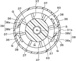
- FIG. 3 is a cross-sectional view taken along the line AA in FIG. 2.
- the present invention is applied to a check valve integrated cut valve in which a cut valve for preventing leakage of fuel to the outside of the fuel tank and a check valve for adjusting the pressure in the fuel tank are integrated. is there.
- the float valve device of the present invention can also be applied to a valve device or the like in which a full tank regulating valve and a check valve are integrated.
- the check valve integrated cut valve 10 (hereinafter referred to as “integrated valve 10”) to which the float valve device of the present invention is applied has an opening 33 a in this embodiment.
- a housing 20 provided with a valve chamber 34 communicating with the inside of the fuel tank below through the partition wall 33, a vent chamber 35 communicating with the outside of the fuel tank on the top, and the valve chamber 34 of this housing 20 can be raised and lowered.
- a check valve 70 which is disposed in the ventilation chamber 35 so as to be movable up and down.
- the housing 20 in this embodiment includes a housing main body 30 having a substantially cylindrical shape, a lower cap 40 attached to a lower opening of the housing main body 30, and an upper portion of the housing main body 30.
- the upper cap 50 is attached to the opening.
- the housing body 30 has a substantially cylindrical peripheral wall 31 having a lower portion 31 b whose diameter is larger than that of the upper portion 31 a, and the partition is placed at a predetermined position above the peripheral wall 31.
- a wall 33 is provided.
- An opening 33a is formed at the center of the partition wall 33, and the lower surface periphery of the opening 33a protrudes.
- the housing main body 30 is formed with the valve chamber 34 on the lower side through the partition wall 33 and the vent chamber 35 on the upper side.
- a plurality of locking holes 31 c are formed at the periphery of the upper opening of the peripheral wall 31, and a plurality of locking recesses 31 d are formed at the upper end of the peripheral wall 31.
- a rib 31e for guiding the raising / lowering operation of the check valve 70 is formed on the inner circumference of the peripheral wall 31 where the vent chamber 35 is formed.
- a plurality of locking projections 31 f are projected from the outer peripheral edge of the lower opening of the peripheral wall 31.
- a plurality of through holes 36 communicating with the inside of the housing body 30 are formed at predetermined intervals along the axial direction above the lower portion 31b of the peripheral wall 31 (see FIGS. 1 and 2).
- a plurality of through holes 36 formed along these axial directions are formed in a plurality of rows at predetermined intervals in the circumferential direction of the peripheral wall 31 (see FIGS. 1 and 4).
- a fuel scattering prevention wall 38 that covers the through hole 36 with a predetermined gap G between the inner periphery of the valve chamber 34 is formed.
- the fuel scattering prevention wall 38 extends downward from the lower end of the upper portion 31 a of the peripheral wall 31, and extends along the circumferential direction of the peripheral wall 31.
- the cross-section along the AA arrow line in FIG. 2 it comprises a second wall portion 38b that connects one end portion of the first wall portion 38a in the circumferential direction and the inner periphery of the lower portion 31b of the peripheral wall 31.
- a substantially L shape is formed, and a gap G is formed between the peripheral wall 31 and the outer peripheral wall 31.
- each of the housing side guide ribs 37 has a length that reaches the upper portion when the float valve body 60 is lowered, and extends from the lower surface of the partition wall 33 to the inner periphery of the upper portion 31 a of the housing body 30. It extends in the axial direction halfway.
- each of the housing side guide ribs 37 has a thin plate shape, has an equal interval along the circumferential direction on the inner periphery of the valve chamber 34, and the protrusion direction tip is the axis S of the housing 20.
- housing-side guide ribs 37 are provided, but two may be provided at opposite positions on the circumference of the valve chamber, or three may be provided at equal intervals in the circumferential direction. Preferably, 6 to 8 are provided at predetermined intervals along the line.
- the lower cap 40 attached to the lower opening of the housing main body 30 has a bottomed cylindrical shape, and a locking hole 41 for locking the locking protrusion 31f of the housing main body 30 to the outer peripheral surface thereof. Is formed.
- the upper cap 50 attached to the upper opening of the housing body 30 has a lid shape whose upper surface is closed, and can be bent through a slit 52 on its peripheral surface.
- a locking claw 53 that locks in the locking hole 31c of the peripheral wall 31 and a locking projection 55 that protrudes from the periphery of the upper end and fits in the locking recess 31d of the peripheral wall 31 are formed.
- An outer case (not shown) is mounted on the outer periphery of the housing 20 having the above structure, and the integrated valve 10 is attached to a fuel tank (not shown) via the outer case. ing.
- the float valve body 60 that can be moved up and down in the valve chamber 34 has a base 61 that is disposed below and an outer diameter smaller than that of the base 61, and is upward from the center of the upper surface of the base 61. And an insertion portion 63 projecting toward the.
- the insertion portion 63 has an outer diameter adapted to the interval W (see FIG. 2) between the plurality of housing-side guide ribs 37, and when the float valve body 60 descends (see FIG. 2) and rises (see FIG. 3).
- the upper portion is formed with a length inserted into the inner periphery of the plurality of housing side guide ribs 37.
- a protrusion 63 a that comes in contact with and separates from the opening 33 a of the partition wall 33 is projected from the center of the upper end of the insertion portion 63 of the float valve body 60.
- a hollow recess 65 is formed at the center of the lower surface of the float valve body 60, and an annular spring accommodating recess 66 is formed on the outer periphery thereof.
- the housing-side guide rib 37 has A plurality of float-side guide ribs 67 extending in the axial direction with a length that does not interfere with each other and formed at predetermined intervals in the circumferential direction are provided. As shown in FIG. 1, the float-side guide rib 67 of the present embodiment protrudes from the lower end to the upper end at an equal interval in the circumferential direction on the outer periphery of the base portion 61.
- eight float-side guide ribs 67 are provided, but two may be provided at opposing positions on the outer periphery of the base 61, or three may be provided at equal intervals in the circumferential direction. It is preferable to provide 6 to 8 pieces at predetermined intervals along the direction.
- the float valve body 60 of this embodiment has a base portion 61 having a large outer diameter and an insertion portion 63 having a smaller outer diameter. There is no particular limitation.
- the float valve body 60 having the above-described shape is accommodated in the valve chamber 34 of the housing body 30, the upper portion of the insertion portion 63 is inserted into the inner periphery of the plurality of housing side guide ribs 37, and the float valve spring 45 is The housing body is housed in the spring housing recess 66 of the float valve body 60, and the other end is supported on the bottom surface of the lower cap 40. In this state, the outer periphery of the lower cap 40 is placed on the outer periphery of the lower opening of the housing body 30.
- the locking cap 31f of the 30 is locked in the locking hole 41 of the lower cap 40, so that the lower cap 40 is attached to the lower opening of the housing body 30, and the float valve body 60 can be moved up and down in the valve chamber 34. It is accommodated (see FIGS. 2 and 3).
- the float valve body 60 when the float valve body 60 is housed in the valve chamber 34 so as to be able to move up and down, it interferes with the housing side guide rib 37 formed on the inner peripheral upper part of the valve chamber 34 of the housing 20 and the housing side guide rib 37 of the float valve body 60.
- the float-side guide rib 67 extending in the axial direction with a length that is not long, there is provided a wide gap region C in which there is no guide rib on either the housing 20 side or the float valve body 60 side.
- the through hole 36 of the housing 20 is formed at a position aligned with the wide gap region C, and the fuel scattering prevention wall 38 is formed.
- the float valve spring 45 is compressed by its own weight, and the float valve body 60 is normally in contact with the bottom surface of the lower cap 40 (see FIG. 2).
- the buoyancy of the float valve body 60 itself is added to the urging force of the float valve spring 45, the float valve body 60 rises, and the projection 63a becomes The opening 33a of the partition wall 33 is closed (see FIG. 3).
- the check valve 70 disposed in the ventilation chamber 35 of the housing 20 includes a casing 71 provided with through holes 71 a and 71 b on both upper and lower surfaces, and the casing 71.
- the valve body 73 is arranged so as to be movable up and down, and mainly includes a built-in spring 75 that urges the valve body 73 toward the upper through hole 71a.
- the check valve 70 is housed in the ventilation chamber 35 of the housing 20 so as to be movable up and down, and comes into contact with and separates from the upper peripheral edge of the opening 33 a of the partition wall 33 of the housing 20.
- the lower end of the check valve biasing spring 77 is brought into contact with the upper surface of the casing 71 of the check valve 70 accommodated in the ventilation chamber 35.
- the engaging protrusion 55 of the upper cap 50 is fitted into the engaging recess 31 d of the housing body 30, and the engaging claw 53 of the upper cap 50 is engaged with the engaging hole 31 c of the housing body 30.
- the upper cap 50 is attached to the upper opening of the housing 20. In this state, the upper end of the check valve urging spring 77 is compressed by the upper cap 50, and the check valve 70 is urged toward the opening 33 a of the partition wall 33 of the housing 20. It is supposed to be blocked.
- the integrated valve 10 to which the float valve device of the present invention is applied is attached to the upper wall of the fuel tank via an external case (not shown) communicating with an evaporation pipe connected to the canister.
- an external case not shown
- the float valve body 60 is lowered and the opening 33a of the partition wall 33 is open (see FIG. 2).
- the opening 33a of the partition wall 33 is closed by the check valve 70 biased by the check valve biasing spring 77 (FIG. 2, FIG. 2). 3).
- the check valve 70 resists the biasing force of the check valve biasing spring 77. rises to open the opening 33a, and the fuel vapor flows into the ventilation chamber 35 through the opening 33a.
- the canister outside the fuel tank or the like passes through the slit 52 (see FIG. 1) of the upper cap 50 or the external case. To reduce the pressure in the fuel tank.
- the pressure in the fuel tank becomes a negative pressure greater than or equal to a predetermined value with respect to the outside air pressure
- the outside air introduced through the outer case or the slit 52 is introduced into the ventilation chamber 35 and the valve body 73 is pressed.
- the valve element 73 moves downward against the urging force of the built-in spring 75 to open the through hole 71a on the upper surface of the check valve, and the outside air passes through the through hole 71b on the lower surface of the check valve and the opening 33a of the housing 20. Is introduced into the valve chamber 34 and flows into the fuel tank, and the negative pressure state in the fuel tank is eliminated.
- the insertion portion 63 of the float valve body 60 is guided by the housing-side guide rib 37 extending to the insertion portion 63 of the float valve body 60, and the inner peripheral surface of the lower portion 31b of the peripheral wall 31 of the housing 20 Since the base 61 of the float valve body 60 is guided by the float side guide rib 67 adjacent to the float, the float valve body 60 can be lifted without tilting, and the projection 63a at the center of the upper end thereof is formed on the lower surface of the opening 33a. It is possible to enhance the sealing performance of the opening 33a by firmly abutting on the side inner periphery.
- the fuel may flow into the valve chamber 34 from the through hole 36 formed in the housing 20.
- a wide gap region C is formed between the housing side guide rib 37 and the float side guide rib 67, where there is no guide rib on either the housing 20 side or the float valve body 60 side.
- the gap between the inner periphery of the valve chamber 34 of the housing 20 and the outer periphery of the float valve body 60 can be secured widely, the fuel that has flowed into the valve chamber 34 from the through hole 36 can be obtained. Therefore, it is possible to prevent the sucked-up behavior, and it is possible to effectively prevent the air from flowing into the ventilation chamber 35 from the opening 33a of the partition wall 33.
- the fuel suction phenomenon can be prevented, it is possible to make it difficult for the fuel to accumulate between the valve chamber 34 of the housing 20 and the float valve body 60, and the fuel is obstructed when the float valve body 60 is moved up and down. Can be prevented, and the dynamic performance of the float valve body 60 can be improved, so that it can be raised and lowered smoothly.
- the fuel that has flowed into the valve chamber 34 from the through hole 36 passes between the wide gap region C and the plurality of float side guide ribs 67 and is sequentially discharged from the hole on the bottom surface of the lower cap 40. It is like that.
- the fuel in the housing 20 can be prevented from flowing into the ventilation chamber 35 from the opening 33a, there is no fear of adversely affecting a canister or the like disposed outside the fuel tank.
- a fuel scattering prevention wall 38 that covers a through hole 36 provided in the wide gap region C with a predetermined gap between the inner periphery of the valve chamber 34 and the inner periphery of the valve chamber 34. Therefore, even if the fuel flows into the housing 20 through the through hole 36, it can be made difficult to collide with the fuel scattering prevention wall 38 and be sucked up, and the opening 33a of the partition wall 33 can be prevented. Can be further prevented from entering the ventilation chamber 35 side. Further, since the fuel scattering prevention wall 38 is disposed in the wide gap region C, even if the fuel scattering prevention wall 38 itself swells due to the fuel flowing into the housing 20, it is pressed or contacted by the float valve body 60. It is possible to prevent the float valve body 60 from moving up and down smoothly.
Abstract
Provided is a float valve device wherein the lifting action of a float valve body can be reliably guided and the up-suction of fuel that has flowed into a housing from a through-hole can be prevented. This float device comprises a housing (20) provided with a valve chest (34) and a draft chamber (35) that have disposed therebetween a partition (33) having an opening (33a), and a float valve body (60) that is disposed within the valve chest (34) so as to be liftable. A plurality of housing side guide ribs (37) are provided in the upper part of the valve chest (34) on the inner periphery thereof. Float side guide ribs (67) are provided to the lower part of the float valve body (60) on outer periphery thereof, and are formed to a length that will not interfere with the housing side guide ribs (37) when the float side guide ribs (67) come into contact with the opening (33a). A wide gap region (C) is provided between the housing side guide ribs (37) and the float side guide ribs (67), and through holes (36) that communicate with the interior of a fuel tank are formed in the wide gap region (C) of the housing (20).
Description
本発明は、自動車等の燃料タンクに取付けられ、カットバルブや満タン規制バルブ等に用いられるフロート弁装置に関する。
The present invention relates to a float valve device which is attached to a fuel tank of an automobile or the like and used for a cut valve, a full tank regulating valve or the like.
例えば、自動車の燃料タンクには、自動車が旋回したり傾いたりしたときに、燃料タンク内の燃料が、燃料タンク外へ漏れるのを防止するカットバルブや、給油時に給油量の上限値で給油を停止させるための満タン規制バルブ等が取付けられている。
For example, the fuel tank of an automobile is supplied with a cut valve that prevents the fuel in the fuel tank from leaking out of the fuel tank when the automobile is turned or tilted, or the upper limit of the amount of oil supplied when refueling. A full tank control valve, etc. for stopping is installed.
上記のカットバルブや満タン規制バルブは、例えば、開口部を有する仕切壁により上方空間及び下方空間が画成されたハウジングと、該ハウジングの下方空間内に昇降可能に配置されたフロート弁体とを備えるものが用いられている。そして、燃料タンク内の燃料液面に応じて、フロート弁体が昇降し、仕切壁の開口部を開閉することにより、燃料漏れや満タン規制を図るものとなっている。
The cut valve and the full tank regulating valve include, for example, a housing in which an upper space and a lower space are defined by a partition wall having an opening, and a float valve body disposed so as to be movable up and down in the lower space of the housing. What is provided with is used. And according to the fuel liquid level in a fuel tank, a float valve body raises / lowers, and the fuel leakage and a full tank regulation are aimed at by opening and closing the opening part of a partition wall.
また、仕切壁の開口部にフロート弁体が当接する際に、フロート弁体が傾いていると、開口部周縁にフロート弁体がしっかりと当接せず、隙間が生じてしまう場合がある。そのため、フロート弁体を傾かせることなく昇降させるための、ガイド構造を設けたフロート弁装置が用いられている。
In addition, when the float valve body is in contact with the opening of the partition wall, if the float valve body is inclined, the float valve body may not be firmly in contact with the periphery of the opening, and a gap may be generated. Therefore, a float valve device provided with a guide structure for raising and lowering the float valve body without tilting is used.
このようなガイド構造を有するものとして、下記特許文献1には、連通孔を有する上壁により通気室及び弁室が形成された弁ケースと、この弁ケースの前記弁室内に昇降可能に配置されたフロート弁体とを備えたフロート弁装置が記載されており、前記フロート弁体の外周に上下方向に伸びるリブが形成され、このリブが弁ケース内周に摺接することで、フロート弁体の昇降動作のガイドがなされるようになっている。前記リブは、フロート弁体外周の下端から上端に至るまで、フロート弁体外周の全長に亘って形成されている。また、弁ケースの周壁には、弁ケース内に連通する透孔が形成されており、流体が出入り可能となっている。
As having such a guide structure, the following Patent Document 1 discloses a valve case in which a ventilation chamber and a valve chamber are formed by an upper wall having a communication hole, and a valve case that can be moved up and down in the valve chamber. A float valve device including a float valve body is described, and a rib extending in the vertical direction is formed on the outer periphery of the float valve body, and the rib is in sliding contact with the inner periphery of the valve case, so that the float valve body A guide for the raising and lowering operation is made. The rib is formed over the entire length of the outer periphery of the float valve body from the lower end to the upper end of the outer periphery of the float valve body. Further, a through hole communicating with the inside of the valve case is formed in the peripheral wall of the valve case so that fluid can enter and exit.
しかしながら、上記特許文献1のフロート弁装置では、フロート弁体外周の全長に亘って形成された、弁ケース内周に摺接するリブにより、弁ケース内周とフロート弁体外周との間隔が非常に狭くなっている。そのため、透孔から弁ケース内に燃料が流入したとき、弁ケース内周とフロート弁体外周との狭い間隔の部分において、燃料が吸い上げられてしまって、上壁の連通孔から通気室側に流入してしまうことがあった。このような燃料の吸い上げ現象が生じると、フロート弁体の動的性能に支障をきたし、また、連通孔から通気室側に流出した燃料によって、燃料タンク外に配置されたキャニスタ等に悪影響を生じる怖れがある。
However, in the float valve device of the above-mentioned Patent Document 1, the gap between the inner periphery of the valve case and the outer periphery of the float valve body is very large due to the rib formed over the entire length of the outer periphery of the float valve body and slidingly contacting the inner periphery of the valve case. It is narrower. Therefore, when the fuel flows into the valve case from the through hole, the fuel is sucked up at the narrow space between the inner periphery of the valve case and the outer periphery of the float valve body, and the communication hole on the upper wall leads to the vent chamber side. In some cases, it would flow in. When such a fuel uptake phenomenon occurs, the dynamic performance of the float valve body is hindered, and the fuel that has flowed out from the communication hole to the ventilation chamber side adversely affects the canister disposed outside the fuel tank. I'm scared.
したがって、本発明の目的は、フロート弁体の昇降動作を確実にガイドすることができると共に、透孔からハウジング内に流入した燃料の吸い上げ現象を防止することができる、フロート弁装置を提供することにある。
Accordingly, an object of the present invention is to provide a float valve device that can reliably guide the lifting and lowering operation of the float valve body and can prevent the suction of fuel flowing into the housing from the through hole. It is in.
上記目的を達成するため、本発明のフロート弁装置は、開口部が形成された仕切壁を介して、下方に燃料タンク内に連通する弁室、上方に燃料タンク外に連通する通気室が設けられたハウジングと、該ハウジングの前記弁室内に昇降可能に配置されたフロート弁体とを備え、前記ハウジングの前記弁室の内周上部には、前記フロート弁体が下降したときにその上方部分に至る長さで軸方向に伸びると共に、周方向に所定間隔で形成された複数のハウジング側ガイドリブが設けられ、前記フロート弁体は、その上方部分が、前記複数のハウジング側ガイドリブの内周に挿入されると共に、その下部外周に、該フロート弁体が上昇して前記開口部に接触したときに前記ハウジング側ガイドリブに干渉しない長さで軸方向に伸びると共に、周方向に所定間隔で形成されたフロート側ガイドリブが設けられ、前記ハウジングのハウジング側ガイドリブと、前記フロート弁体のフロート側ガイドリブとの間には、前記ハウジング側にも前記フロート弁体側にもガイドリブがない、広間隙領域が設けられており、前記ハウジングの前記広間隙領域に、前記燃料タンク内に連通する透孔が形成されていることを特徴とする。
In order to achieve the above object, the float valve device of the present invention is provided with a valve chamber communicating with the inside of the fuel tank below and a vent chamber communicating with the outside of the fuel tank via the partition wall formed with the opening. And a float valve body disposed in the valve chamber of the housing so as to be movable up and down, and an upper portion of the inner periphery of the valve chamber of the housing has an upper portion when the float valve body is lowered. A plurality of housing-side guide ribs extending in the axial direction at a predetermined length in the circumferential direction are provided, and the float valve element has an upper portion at the inner periphery of the plurality of housing-side guide ribs. In addition to being inserted into the outer periphery of the lower portion thereof, the float valve body rises in the axial direction with a length that does not interfere with the housing-side guide rib when it comes into contact with the opening, and in the circumferential direction. Float side guide ribs formed at a predetermined interval are provided, and there are no guide ribs on either the housing side or the float valve body side between the housing side guide rib of the housing and the float side guide rib of the float valve body, A wide gap region is provided, and a through hole communicating with the inside of the fuel tank is formed in the wide gap region of the housing.
本発明のフロート弁装置においては、前記ハウジングの前記弁室の内周には、前記広間隙領域に設けられた透孔を、前記弁室の内周との間に所定の隙間を設けてカバーする燃料飛散防止壁が形成されていることが好ましい。
In the float valve device of the present invention, the inner periphery of the valve chamber of the housing is covered with a through hole provided in the wide gap region with a predetermined gap between the inner periphery of the valve chamber. It is preferable that a fuel scattering prevention wall is formed.
本発明によれば、燃料タンク内の燃料液面の変動に伴うフロート弁体の昇降動作が、フロート弁体の上方部分に至る長さで伸びたハウジング側ガイドリブ、及び、フロート弁体の下部外周に形成されたフロート側ガイドリブによってガイドされるので、フロート弁体を傾かせることなく昇降動作させることができ、仕切壁の開口部にしっかりと当接させて、開口部のシール性を高めることができる。
According to the present invention, the lifting and lowering operation of the float valve body accompanying the change in the fuel level in the fuel tank is performed by the housing-side guide rib that extends to reach the upper portion of the float valve body, and the lower outer periphery of the float valve body Because the float is guided by the float-side guide ribs formed on the float, the float valve body can be moved up and down without tilting, and it can be firmly brought into contact with the opening of the partition wall to improve the sealing performance of the opening. it can.
そして、ハウジング側リブとフロート側リブとの間に形成された広間隙領域によって、ハウジングの弁室内周とフロート弁体外周との間隔を広く確保することができ、そこに燃料タンク内に連通する透孔が形成されているので、透孔からハウジング内に流入した燃料が吸い上げられて仕切壁の開口部から通気室へと流入してしまうことを効果的に防止することができる。
A wide gap region formed between the housing side rib and the float side rib can secure a wide space between the valve chamber outer periphery of the housing and the float valve body outer periphery, and communicates with the inside of the fuel tank. Since the through hole is formed, it is possible to effectively prevent the fuel that has flowed into the housing from the through hole and sucked into the ventilation chamber from the opening of the partition wall.
以下、図1~4を参照して、本発明のフロート弁装置の一実施形態について説明する。この実施形態は、燃料タンク外への燃料の漏出を防止するカットバルブと、燃料タンク内の圧力を調整するチェックバルブとを一体化したチェックバルブ一体型カットバルブに、本発明を適用したものである。なお、本発明のフロート弁装置は、満タン規制バルブと、チェックバルブとを一体化した弁装置等にも適用することもできる。
Hereinafter, an embodiment of the float valve device of the present invention will be described with reference to FIGS. In this embodiment, the present invention is applied to a check valve integrated cut valve in which a cut valve for preventing leakage of fuel to the outside of the fuel tank and a check valve for adjusting the pressure in the fuel tank are integrated. is there. The float valve device of the present invention can also be applied to a valve device or the like in which a full tank regulating valve and a check valve are integrated.
図1に示すように、本発明のフロート弁装置が適用されるチェックバルブ一体型カットバルブ10(以下、「一体型バルブ10」という)は、本実施形態の場合、開口部33aが形成された仕切壁33を介して、下方に燃料タンク内に連通する弁室34、上方に燃料タンク外に連通する通気室35が設けられたハウジング20と、このハウジング20の前記弁室34内に昇降可能に配置されたフロート弁体60と、前記通気室35内に昇降可能に配置されたチェックバルブと70とを備えている。
As shown in FIG. 1, the check valve integrated cut valve 10 (hereinafter referred to as “integrated valve 10”) to which the float valve device of the present invention is applied has an opening 33 a in this embodiment. A housing 20 provided with a valve chamber 34 communicating with the inside of the fuel tank below through the partition wall 33, a vent chamber 35 communicating with the outside of the fuel tank on the top, and the valve chamber 34 of this housing 20 can be raised and lowered. And a check valve 70, which is disposed in the ventilation chamber 35 so as to be movable up and down.
この実施形態における前記ハウジング20は、図1に示すように、略筒状をなしたハウジング本体30と、このハウジング本体30の下方開口部に装着される下部キャップ40と、前記ハウジング本体30の上方開口部に装着される上部キャップ50とから構成されている。
As shown in FIG. 1, the housing 20 in this embodiment includes a housing main body 30 having a substantially cylindrical shape, a lower cap 40 attached to a lower opening of the housing main body 30, and an upper portion of the housing main body 30. The upper cap 50 is attached to the opening.
図1及び図2に示すように、ハウジング本体30は、下部31bが上部31aよりも拡径した形状の略円筒状の周壁31を有しており、この周壁31の上方の所定位置に前記仕切壁33が設けられている。この仕切壁33の中央に開口部33aが形成されており、この開口部33aの下面周縁が突出した形状をなしている。ハウジング本体30には、前記仕切壁33を介して、その下方側に前記弁室34が形成され、上方側に前記通気室35が形成されている。また、前記周壁31の上方開口部周縁に複数の係止孔31cが形成され、同周壁31の上端部に複数の係止凹部31dが形成されている。更に、周壁31の、通気室35が形成された部分の内周には、チェックバルブ70の昇降動作をガイドするためのリブ31eが形成されている。また、周壁31の下方開口部の外周縁には、複数の係止突起31fが突設されている。
As shown in FIGS. 1 and 2, the housing body 30 has a substantially cylindrical peripheral wall 31 having a lower portion 31 b whose diameter is larger than that of the upper portion 31 a, and the partition is placed at a predetermined position above the peripheral wall 31. A wall 33 is provided. An opening 33a is formed at the center of the partition wall 33, and the lower surface periphery of the opening 33a protrudes. The housing main body 30 is formed with the valve chamber 34 on the lower side through the partition wall 33 and the vent chamber 35 on the upper side. A plurality of locking holes 31 c are formed at the periphery of the upper opening of the peripheral wall 31, and a plurality of locking recesses 31 d are formed at the upper end of the peripheral wall 31. Further, a rib 31e for guiding the raising / lowering operation of the check valve 70 is formed on the inner circumference of the peripheral wall 31 where the vent chamber 35 is formed. A plurality of locking projections 31 f are projected from the outer peripheral edge of the lower opening of the peripheral wall 31.
また、周壁31の下部31bの上方には、ハウジング本体30内に連通する透孔36が、軸方向に沿って所定間隔で複数形成されている(図1,2参照)。これらの軸方向に沿って形成された複数の透孔36が、周壁31の周方向に所定間隔をあけて複数列形成されている(図1,4参照)。
Further, a plurality of through holes 36 communicating with the inside of the housing body 30 are formed at predetermined intervals along the axial direction above the lower portion 31b of the peripheral wall 31 (see FIGS. 1 and 2). A plurality of through holes 36 formed along these axial directions are formed in a plurality of rows at predetermined intervals in the circumferential direction of the peripheral wall 31 (see FIGS. 1 and 4).
更に、ハウジング本体30の弁室34の内周には、前記透孔36を、弁室34の内周との間に所定の隙間Gを設けてカバーする燃料飛散防止壁38が形成されている。図2及び図4に示すように、この燃料飛散防止壁38は、周壁31の上部31aの下端から下方に延出し、周壁31の周方向に沿って延設された第1壁部38aと、この第1壁部38aの周方向の一端部と周壁31の下部31b内周とを連結する第2壁部38bとからなり、図2のA-A矢示線に沿った断面を見たとき、図4に示すように略L字状をなし、周壁31との間に隙間Gが形成された構造となっている。
Further, on the inner periphery of the valve chamber 34 of the housing body 30, a fuel scattering prevention wall 38 that covers the through hole 36 with a predetermined gap G between the inner periphery of the valve chamber 34 is formed. . As shown in FIGS. 2 and 4, the fuel scattering prevention wall 38 extends downward from the lower end of the upper portion 31 a of the peripheral wall 31, and extends along the circumferential direction of the peripheral wall 31. When the cross-section along the AA arrow line in FIG. 2 is seen, it comprises a second wall portion 38b that connects one end portion of the first wall portion 38a in the circumferential direction and the inner periphery of the lower portion 31b of the peripheral wall 31. As shown in FIG. 4, a substantially L shape is formed, and a gap G is formed between the peripheral wall 31 and the outer peripheral wall 31.
また、図1に示すように、前記ハウジング本体30の弁室34の内周上部には、周方向に所定間隔をあけて、複数のハウジング側ガイドリブ37が設けられている。図2を併せて参照すると、各ハウジング側ガイドリブ37は、フロート弁体60が下降したときにその上方部分に至る長さで、前記仕切壁33の下面から前記ハウジング本体30の上部31a内周の途中まで軸方向に伸びている。この実施形態では、各ハウジング側ガイドリブ37は薄肉板状をなし、前記弁室34の内周に周方向に沿って均等な間隔をあけて、かつ、その突出方向先端をハウジング20の軸心Sに向けて突設されている(図4参照)。この実施形態では、8個のハウジング側ガイドリブ37が設けられているが、弁室内周の対向した位置に2個設けたり、周方向に均等な間隔で3個設けたりしてもよく、周方向に沿って所定間隔で6~8個設けることが好ましい。
As shown in FIG. 1, a plurality of housing-side guide ribs 37 are provided on the inner peripheral upper portion of the valve chamber 34 of the housing body 30 at a predetermined interval in the circumferential direction. Referring also to FIG. 2, each of the housing side guide ribs 37 has a length that reaches the upper portion when the float valve body 60 is lowered, and extends from the lower surface of the partition wall 33 to the inner periphery of the upper portion 31 a of the housing body 30. It extends in the axial direction halfway. In this embodiment, each of the housing side guide ribs 37 has a thin plate shape, has an equal interval along the circumferential direction on the inner periphery of the valve chamber 34, and the protrusion direction tip is the axis S of the housing 20. (See FIG. 4). In this embodiment, eight housing-side guide ribs 37 are provided, but two may be provided at opposite positions on the circumference of the valve chamber, or three may be provided at equal intervals in the circumferential direction. Preferably, 6 to 8 are provided at predetermined intervals along the line.
上記ハウジング本体30の下方開口部に装着される下部キャップ40は、有底円筒状をなしており、その外周面にハウジング本体30の前記係止突起31fが係止される、係止孔41が形成されている。
The lower cap 40 attached to the lower opening of the housing main body 30 has a bottomed cylindrical shape, and a locking hole 41 for locking the locking protrusion 31f of the housing main body 30 to the outer peripheral surface thereof. Is formed.
また、図1に示すように、上記ハウジング本体30の上方開口部に装着される上部キャップ50は、上面が閉塞した蓋状をなしており、その周面にスリット52を介して撓み可能とされ、前記周壁31の係止孔31cに係止する係止爪53と、上端周縁から突設され、前記周壁31の係止凹部31dに嵌合する係止凸部55とが形成されている。
Further, as shown in FIG. 1, the upper cap 50 attached to the upper opening of the housing body 30 has a lid shape whose upper surface is closed, and can be bent through a slit 52 on its peripheral surface. A locking claw 53 that locks in the locking hole 31c of the peripheral wall 31 and a locking projection 55 that protrudes from the periphery of the upper end and fits in the locking recess 31d of the peripheral wall 31 are formed.
なお、上記構造をなしたハウジング20の外周には、図示しない外部ケースが装着されるようになっており、この外部ケースを介して一体型バルブ10が、図示しない燃料タンクに取付けられるようになっている。
An outer case (not shown) is mounted on the outer periphery of the housing 20 having the above structure, and the integrated valve 10 is attached to a fuel tank (not shown) via the outer case. ing.
前記弁室34内に昇降可能に配置されるフロート弁体60は、この実施形態の場合、下方に配置された基部61と、この基部61よりも外径が小さく、基部61の上面中央から上方に向けて突出した挿入部63とを有している。前記挿入部63は、複数のハウジング側ガイドリブ37どうしの間隔W(図2参照)に適合した外径で、かつ、フロート弁体60の下降時(図2参照)及び上昇時(図3参照)に、その上方部分が複数のハウジング側ガイドリブ37の内周に挿入される長さで形成されている。
In this embodiment, the float valve body 60 that can be moved up and down in the valve chamber 34 has a base 61 that is disposed below and an outer diameter smaller than that of the base 61, and is upward from the center of the upper surface of the base 61. And an insertion portion 63 projecting toward the. The insertion portion 63 has an outer diameter adapted to the interval W (see FIG. 2) between the plurality of housing-side guide ribs 37, and when the float valve body 60 descends (see FIG. 2) and rises (see FIG. 3). Further, the upper portion is formed with a length inserted into the inner periphery of the plurality of housing side guide ribs 37.
また、フロート弁体60の挿入部63の上端中央からは、前記仕切壁33の開口部33aに接離する突起63aが突設されている。更に、フロート弁体60の下面中央には肉抜き凹部65が形成され、その外周には環状のバネ収容凹部66が形成されている。
Further, a protrusion 63 a that comes in contact with and separates from the opening 33 a of the partition wall 33 is projected from the center of the upper end of the insertion portion 63 of the float valve body 60. Further, a hollow recess 65 is formed at the center of the lower surface of the float valve body 60, and an annular spring accommodating recess 66 is formed on the outer periphery thereof.
更に、フロート弁体60の、下方に配置された基部61の外周には、該フロート弁体60が上昇して前記開口部33aに接触したときに(図3参照)、前記ハウジング側ガイドリブ37に干渉しない長さで軸方向に伸びると共に、周方向に所定間隔で形成されたフロート側ガイドリブ67が複数設けられている。図1に示すように、本実施形態のフロート側ガイドリブ67は、基部61の外周において、周方向に均等な間隔を設けて、下端から上端に亘って突設されている。この実施形態では、8個のフロート側ガイドリブ67が設けられているが、基部61の外周の対向した位置に2個設けたり、周方向に均等な間隔で3個設けたりしてもよく、周方向に沿って所定間隔で6~8個設けることが好ましい。
Further, on the outer periphery of the base 61 disposed below the float valve body 60, when the float valve body 60 rises and contacts the opening 33 a (see FIG. 3), the housing-side guide rib 37 has A plurality of float-side guide ribs 67 extending in the axial direction with a length that does not interfere with each other and formed at predetermined intervals in the circumferential direction are provided. As shown in FIG. 1, the float-side guide rib 67 of the present embodiment protrudes from the lower end to the upper end at an equal interval in the circumferential direction on the outer periphery of the base portion 61. In this embodiment, eight float-side guide ribs 67 are provided, but two may be provided at opposing positions on the outer periphery of the base 61, or three may be provided at equal intervals in the circumferential direction. It is preferable to provide 6 to 8 pieces at predetermined intervals along the direction.
また、この実施形態のフロート弁体60は、大きな外径の基部61及びそれよりも小さい外径の挿入部63を有する段階的に縮径する形状をなしているが、ほぼ一定径で伸びる円筒状にしてもよく、特に限定されるものではない。
In addition, the float valve body 60 of this embodiment has a base portion 61 having a large outer diameter and an insertion portion 63 having a smaller outer diameter. There is no particular limitation.
そして、上記形状のフロート弁体60をハウジング本体30の弁室34内に収容して、挿入部63の上方部分を複数のハウジング側ガイドリブ37の内周に挿入すると共に、フロート弁用バネ45を、フロート弁体60のバネ収容凹部66に収容し、その他端を下部キャップ40の底面に支持させ、その状態でハウジング本体30の下方開口部外周に下部キャップ40の外周面を被せて、ハウジング本体30の係止突起31fを下部キャップ40の係止孔41に係止させることにより、ハウジング本体30の下方開口部に下部キャップ40が装着され、弁室34内にフロート弁体60が昇降可能に収容されるようになっている(図2及び図3参照)。
The float valve body 60 having the above-described shape is accommodated in the valve chamber 34 of the housing body 30, the upper portion of the insertion portion 63 is inserted into the inner periphery of the plurality of housing side guide ribs 37, and the float valve spring 45 is The housing body is housed in the spring housing recess 66 of the float valve body 60, and the other end is supported on the bottom surface of the lower cap 40. In this state, the outer periphery of the lower cap 40 is placed on the outer periphery of the lower opening of the housing body 30. The locking cap 31f of the 30 is locked in the locking hole 41 of the lower cap 40, so that the lower cap 40 is attached to the lower opening of the housing body 30, and the float valve body 60 can be moved up and down in the valve chamber 34. It is accommodated (see FIGS. 2 and 3).
こうして弁室34内にフロート弁体60が昇降可能に収容されると、ハウジング20の弁室34の内周上部に形成されたハウジング側ガイドリブ37と、フロート弁体60のハウジング側ガイドリブ37に干渉しない長さで軸方向に伸びるフロート側ガイドリブ67との間に、ハウジング20側にもフロート弁体60側にもガイドリブがない、広間隙領域Cが設けられるようになっている。そして、この広間隙領域Cに整合する位置に、前記ハウジング20の前記透孔36が形成されると共に、前記燃料飛散防止壁38が形成されている。
Thus, when the float valve body 60 is housed in the valve chamber 34 so as to be able to move up and down, it interferes with the housing side guide rib 37 formed on the inner peripheral upper part of the valve chamber 34 of the housing 20 and the housing side guide rib 37 of the float valve body 60. Between the float-side guide rib 67 extending in the axial direction with a length that is not long, there is provided a wide gap region C in which there is no guide rib on either the housing 20 side or the float valve body 60 side. In addition, the through hole 36 of the housing 20 is formed at a position aligned with the wide gap region C, and the fuel scattering prevention wall 38 is formed.
また、フロート弁用バネ45は、フロート弁体60の自重で圧縮され、常時はフロート弁体60が下部キャップ40の底面上に当接しているが(図2参照)、燃料タンク内の燃料液面が上昇してフロート弁体60の所定高さまで浸漬されると、フロート弁用バネ45の付勢力にフロート弁体60自体の浮力が加わって、フロート弁体60が上昇し、その突起63aが仕切壁33開口部33aを閉塞するようになっている(図3参照)。
The float valve spring 45 is compressed by its own weight, and the float valve body 60 is normally in contact with the bottom surface of the lower cap 40 (see FIG. 2). When the surface rises and is immersed to a predetermined height of the float valve body 60, the buoyancy of the float valve body 60 itself is added to the urging force of the float valve spring 45, the float valve body 60 rises, and the projection 63a becomes The opening 33a of the partition wall 33 is closed (see FIG. 3).
前記ハウジング20の通気室35内に昇降可能に配置されたチェックバルブ70は、図1及び図2に示すように、上下両面に通孔71a,71bを設けたケーシング71と、このケーシング71内に昇降可能に配置され、上方の通孔71aに接離する弁体73と、この弁体73を上方の通孔71aに向けて付勢する内蔵バネ75とから主として構成されている。このチェックバルブ70は、ハウジング20の通気室35内に昇降可能に収容され、前記ハウジング20の仕切壁33の開口部33aの上面周縁に接離するようになっている。
As shown in FIGS. 1 and 2, the check valve 70 disposed in the ventilation chamber 35 of the housing 20 includes a casing 71 provided with through holes 71 a and 71 b on both upper and lower surfaces, and the casing 71. The valve body 73 is arranged so as to be movable up and down, and mainly includes a built-in spring 75 that urges the valve body 73 toward the upper through hole 71a. The check valve 70 is housed in the ventilation chamber 35 of the housing 20 so as to be movable up and down, and comes into contact with and separates from the upper peripheral edge of the opening 33 a of the partition wall 33 of the housing 20.
そして、通気室35内に収容されたチェックバルブ70のケーシング71の上面には、チェックバルブ付勢用バネ77の下端が当接される。また、ハウジング本体30の係止凹部31dに、上部キャップ50の係止凸部55を嵌合させ、ハウジング本体30の係止孔31cに、上部キャップ50の係止爪53を係止させることで、ハウジング20の上方開口部に上部キャップ50が装着される。この状態で、チェックバルブ付勢用バネ77の上端が上部キャップ50により圧縮されて、チェックバルブ70がハウジング20の仕切壁33の開口部33aに向けて付勢され、同開口部33aが常時は閉塞されるようになっている。
The lower end of the check valve biasing spring 77 is brought into contact with the upper surface of the casing 71 of the check valve 70 accommodated in the ventilation chamber 35. In addition, the engaging protrusion 55 of the upper cap 50 is fitted into the engaging recess 31 d of the housing body 30, and the engaging claw 53 of the upper cap 50 is engaged with the engaging hole 31 c of the housing body 30. The upper cap 50 is attached to the upper opening of the housing 20. In this state, the upper end of the check valve urging spring 77 is compressed by the upper cap 50, and the check valve 70 is urged toward the opening 33 a of the partition wall 33 of the housing 20. It is supposed to be blocked.
次に、本発明のフロート弁装置の作用効果について説明する。
Next, the function and effect of the float valve device of the present invention will be described.
本発明のフロート弁装置が適用された一体型バルブ10は、キャニスタに連結されたエバポ配管に連通した図示しない外部ケースを介して、燃料タンクの上壁に取付けられるようになっている。そして、燃料液面がフロート弁体60に浸漬していない場合は、フロート弁体60が下降して、仕切壁33の開口部33aが開いた状態となっている(図2参照)。また、燃料タンク内の圧力が所定値を超えていない状態では、チェックバルブ付勢用バネ77で付勢されたチェックバルブ70により、仕切壁33の開口部33aが閉塞されている(図2,3参照)。
The integrated valve 10 to which the float valve device of the present invention is applied is attached to the upper wall of the fuel tank via an external case (not shown) communicating with an evaporation pipe connected to the canister. When the fuel liquid level is not immersed in the float valve body 60, the float valve body 60 is lowered and the opening 33a of the partition wall 33 is open (see FIG. 2). When the pressure in the fuel tank does not exceed the predetermined value, the opening 33a of the partition wall 33 is closed by the check valve 70 biased by the check valve biasing spring 77 (FIG. 2, FIG. 2). 3).
上記のように、フロート弁体60が下降し開口部33aが開いた状態で、燃料タンク内の圧力が所定値を超えると、チェックバルブ付勢用バネ77の付勢力に抗してチェックバルブ70が上昇して開口部33aが開き、燃料蒸気が開口部33aを通って通気室35に流入し、上部キャップ50のスリット52(図1参照)や外部ケースを介して、燃料タンク外のキャニスタ等へ送られて、燃料タンク内の圧力が低減される。
As described above, when the pressure in the fuel tank exceeds a predetermined value with the float valve body 60 lowered and the opening 33a opened, the check valve 70 resists the biasing force of the check valve biasing spring 77. Rises to open the opening 33a, and the fuel vapor flows into the ventilation chamber 35 through the opening 33a. The canister outside the fuel tank or the like passes through the slit 52 (see FIG. 1) of the upper cap 50 or the external case. To reduce the pressure in the fuel tank.
一方、燃料タンク内の圧力が外気圧に対して所定値以上負圧になると、外部ケースやスリット52を通って導入された外気が通気室35内に導入されて、弁体73が押圧される。すると、内蔵バネ75の付勢力に抗して弁体73が下方に移動して、チェックバルブ上面の通孔71aが開き、外気がチェックバルブ下面の通孔71b及びハウジング20の開口部33aを通って弁室34内に導入されて燃料タンク内へと流入し、燃料タンク内の負圧状態が解消される。
On the other hand, when the pressure in the fuel tank becomes a negative pressure greater than or equal to a predetermined value with respect to the outside air pressure, the outside air introduced through the outer case or the slit 52 is introduced into the ventilation chamber 35 and the valve body 73 is pressed. . Then, the valve element 73 moves downward against the urging force of the built-in spring 75 to open the through hole 71a on the upper surface of the check valve, and the outside air passes through the through hole 71b on the lower surface of the check valve and the opening 33a of the housing 20. Is introduced into the valve chamber 34 and flows into the fuel tank, and the negative pressure state in the fuel tank is eliminated.
そして、車両が旋回したり大きく傾いたり等して、燃料タンク内の燃料液面が上昇して、フロート弁体60に燃料が所定高さ以上浸漬すると、フロート弁用バネ45の付勢力及びフロート弁体60自体に生じる浮力によって、フロート弁体60が浮き上がる。このとき、フロート弁体60の挿入部63に至る長さで伸びたハウジング側ガイドリブ37により、フロート弁体60の挿入部63がガイドされると共に、ハウジング20の周壁31の下部31bの内周面に近接したフロート側ガイドリブ67により、フロート弁体60の基部61がガイドされるので、フロート弁体60を傾かせることなく上昇させることができ、その上端中央の突起63aを、開口部33aの下面側内周にしっかりと当接させて、開口部33aのシール性を高めることができる。
When the fuel level in the fuel tank rises as the vehicle turns or tilts greatly, and the fuel is immersed in the float valve body 60 by a predetermined height or more, the urging force and float of the float valve spring 45 are increased. The float valve body 60 is lifted by the buoyancy generated in the valve body 60 itself. At this time, the insertion portion 63 of the float valve body 60 is guided by the housing-side guide rib 37 extending to the insertion portion 63 of the float valve body 60, and the inner peripheral surface of the lower portion 31b of the peripheral wall 31 of the housing 20 Since the base 61 of the float valve body 60 is guided by the float side guide rib 67 adjacent to the float, the float valve body 60 can be lifted without tilting, and the projection 63a at the center of the upper end thereof is formed on the lower surface of the opening 33a. It is possible to enhance the sealing performance of the opening 33a by firmly abutting on the side inner periphery.
また、車両の旋回や傾き等によって燃料液面が揺れると、ハウジング20に形成された透孔36から弁室34内に燃料が流入することがある。このような場合でも、このフロート弁装置においては、ハウジング側ガイドリブ37とフロート側ガイドリブ67との間に、ハウジング20側にもフロート弁体60側にもガイドリブがない、広間隙領域Cが形成されていて、ハウジング20の弁室34の内周と、フロート弁体60の外周との間隔を広く確保することができるようになっているので、透孔36から弁室34内に流入した燃料が、吸い上げられるような挙動を防止することができ、仕切壁33の開口部33aから通気室35へと流入してしまうことを効果的に防止することができる。
Further, if the fuel level fluctuates due to turning or tilting of the vehicle, the fuel may flow into the valve chamber 34 from the through hole 36 formed in the housing 20. Even in such a case, in this float valve device, a wide gap region C is formed between the housing side guide rib 37 and the float side guide rib 67, where there is no guide rib on either the housing 20 side or the float valve body 60 side. In addition, since the gap between the inner periphery of the valve chamber 34 of the housing 20 and the outer periphery of the float valve body 60 can be secured widely, the fuel that has flowed into the valve chamber 34 from the through hole 36 can be obtained. Therefore, it is possible to prevent the sucked-up behavior, and it is possible to effectively prevent the air from flowing into the ventilation chamber 35 from the opening 33a of the partition wall 33.
また、燃料の吸い上げ現象を防止することができるので、ハウジング20の弁室34とフロート弁体60との間に、燃料を溜まりにくくすることができ、フロート弁体60の昇降動作時に燃料が支障になることを防止して、フロート弁体60の動的性能を向上させて、スムーズに昇降させることができる。なお、この実施形態では、透孔36から弁室34内に流入した燃料は、広間隙領域C及び複数のフロート側ガイドリブ67の間を通って、下部キャップ40の底面の孔から順次排出されるようになっている。また、ハウジング20内の燃料を、開口部33aから通気室35へと流入することを防止することができるので、燃料タンク外に配置されたキャニスタ等に悪影響を生じる怖れもない。
Further, since the fuel suction phenomenon can be prevented, it is possible to make it difficult for the fuel to accumulate between the valve chamber 34 of the housing 20 and the float valve body 60, and the fuel is obstructed when the float valve body 60 is moved up and down. Can be prevented, and the dynamic performance of the float valve body 60 can be improved, so that it can be raised and lowered smoothly. In this embodiment, the fuel that has flowed into the valve chamber 34 from the through hole 36 passes between the wide gap region C and the plurality of float side guide ribs 67 and is sequentially discharged from the hole on the bottom surface of the lower cap 40. It is like that. In addition, since the fuel in the housing 20 can be prevented from flowing into the ventilation chamber 35 from the opening 33a, there is no fear of adversely affecting a canister or the like disposed outside the fuel tank.
また、ハウジング20の弁室34の内周には、広間隙領域Cに設けられた透孔36を、弁室34の内周との間に所定の隙間を設けてカバーする燃料飛散防止壁38が形成されているので、透孔36を通ってハウジング20内に燃料が勢いよく流入しても、燃料飛散防止壁38に衝突して吸い上げられにくくすることができ、仕切壁33の開口部33aから通気室35側に更に入り込みにくくすることができる。また、燃料飛散防止壁38は、広間隙領域Cに配置されているので、ハウジング20内に流入した燃料により、燃料飛散防止壁38自身が膨潤しても、フロート弁体60に押圧されたり接触したりすることを防止することができ、フロート弁体60の昇降動作をスムーズに行わせることができる。
Further, a fuel scattering prevention wall 38 that covers a through hole 36 provided in the wide gap region C with a predetermined gap between the inner periphery of the valve chamber 34 and the inner periphery of the valve chamber 34. Therefore, even if the fuel flows into the housing 20 through the through hole 36, it can be made difficult to collide with the fuel scattering prevention wall 38 and be sucked up, and the opening 33a of the partition wall 33 can be prevented. Can be further prevented from entering the ventilation chamber 35 side. Further, since the fuel scattering prevention wall 38 is disposed in the wide gap region C, even if the fuel scattering prevention wall 38 itself swells due to the fuel flowing into the housing 20, it is pressed or contacted by the float valve body 60. It is possible to prevent the float valve body 60 from moving up and down smoothly.
10 チェックバルブ一体型カットバルブ(一体型バルブ)
20 ハウジング
30 ハウジング本体
33 仕切壁
33a 開口部
34 弁室
35 通気室
36 透孔
37 ハウジング側ガイドリブ
38 燃料飛散防止壁
40 下部キャップ
45 フロート弁用バネ
50 上部キャップ
60 フロート弁体
67 フロート側ガイドリブ
70 チェックバルブ
77 チェックバルブ付勢用バネ
C 広間隙領域
G 隙間 10 Check valve integrated cut valve (integrated valve)
20Housing 30 Housing body 33 Partition wall 33a Opening 34 Valve chamber 35 Venting chamber 36 Through hole 37 Housing side guide rib 38 Fuel scattering prevention wall 40 Lower cap 45 Float valve spring 50 Upper cap 60 Float valve body 67 Float side guide rib 70 Check Valve 77 Check valve biasing spring C Wide gap area G Clearance
20 ハウジング
30 ハウジング本体
33 仕切壁
33a 開口部
34 弁室
35 通気室
36 透孔
37 ハウジング側ガイドリブ
38 燃料飛散防止壁
40 下部キャップ
45 フロート弁用バネ
50 上部キャップ
60 フロート弁体
67 フロート側ガイドリブ
70 チェックバルブ
77 チェックバルブ付勢用バネ
C 広間隙領域
G 隙間 10 Check valve integrated cut valve (integrated valve)
20
Claims (2)
- 開口部が形成された仕切壁を介して、下方に燃料タンク内に連通する弁室、上方に燃料タンク外に連通する通気室が設けられたハウジングと、
該ハウジングの前記弁室内に昇降可能に配置されたフロート弁体とを備え、
前記ハウジングの前記弁室の内周上部には、前記フロート弁体が下降したときにその上方部分に至る長さで軸方向に伸びると共に、周方向に所定間隔で形成された複数のハウジング側ガイドリブが設けられ、
前記フロート弁体は、その上方部分が、前記複数のハウジング側ガイドリブの内周に挿入されると共に、その下部外周に、該フロート弁体が上昇して前記開口部に接触したときに前記ハウジング側ガイドリブに干渉しない長さで軸方向に伸びると共に、周方向に所定間隔で形成されたフロート側ガイドリブが設けられ、
前記ハウジングのハウジング側ガイドリブと、前記フロート弁体のフロート側ガイドリブとの間には、前記ハウジング側にも前記フロート弁体側にもガイドリブがない、広間隙領域が設けられており、
前記ハウジングの前記広間隙領域に、前記燃料タンク内に連通する透孔が形成されていることを特徴とするフロート弁装置。 A housing provided with a valve chamber communicating with the inside of the fuel tank at the lower side and a ventilation chamber communicating with the outside of the fuel tank at the upper side through a partition wall formed with an opening;
A float valve body arranged to be movable up and down in the valve chamber of the housing,
A plurality of housing-side guide ribs formed in the inner circumferential upper portion of the valve chamber of the housing extend in the axial direction with a length reaching the upper portion when the float valve body is lowered, and are formed at predetermined intervals in the circumferential direction. Is provided,
The float valve body has an upper portion inserted into the inner periphery of the plurality of housing-side guide ribs, and the float valve body ascends to the outer periphery of the lower part and contacts the opening. Along with the length that does not interfere with the guide ribs and extending in the axial direction, float side guide ribs formed at predetermined intervals in the circumferential direction are provided,
Between the housing-side guide rib of the housing and the float-side guide rib of the float valve body, there is provided a wide gap region in which there is no guide rib on either the housing side or the float valve body side,
A float valve device, wherein a through hole communicating with the inside of the fuel tank is formed in the wide gap region of the housing. - 前記ハウジングの前記弁室の内周には、前記広間隙領域に設けられた透孔を、前記弁室の内周との間に所定の隙間を設けてカバーする燃料飛散防止壁が形成されている請求項1記載のフロート弁装置。 A fuel scattering prevention wall is formed on the inner periphery of the valve chamber of the housing to cover a through hole provided in the wide gap region with a predetermined gap between the inner periphery of the valve chamber. The float valve device according to claim 1.
Priority Applications (1)
| Application Number | Priority Date | Filing Date | Title |
|---|---|---|---|
| JP2013505842A JPWO2012127918A1 (en) | 2011-03-24 | 2012-02-08 | Float valve device |
Applications Claiming Priority (2)
| Application Number | Priority Date | Filing Date | Title |
|---|---|---|---|
| JP2011-066495 | 2011-03-24 | ||
| JP2011066495 | 2011-03-24 |
Publications (1)
| Publication Number | Publication Date |
|---|---|
| WO2012127918A1 true WO2012127918A1 (en) | 2012-09-27 |
Family
ID=46879086
Family Applications (1)
| Application Number | Title | Priority Date | Filing Date |
|---|---|---|---|
| PCT/JP2012/052842 WO2012127918A1 (en) | 2011-03-24 | 2012-02-08 | Float valve device |
Country Status (2)
| Country | Link |
|---|---|
| JP (1) | JPWO2012127918A1 (en) |
| WO (1) | WO2012127918A1 (en) |
Cited By (3)
| Publication number | Priority date | Publication date | Assignee | Title |
|---|---|---|---|---|
| WO2016056472A1 (en) * | 2014-10-07 | 2016-04-14 | 株式会社ニフコ | Fuel tank valve device |
| JP2019038361A (en) * | 2017-08-24 | 2019-03-14 | 株式会社パイオラックス | Valve device |
| CN110606151A (en) * | 2018-06-15 | 2019-12-24 | 本田技研工业株式会社 | Fuel tank cap structure and straddle type vehicle |
Citations (5)
| Publication number | Priority date | Publication date | Assignee | Title |
|---|---|---|---|---|
| JP2002285925A (en) * | 2001-03-26 | 2002-10-03 | Toyoda Gosei Co Ltd | Fuel shut-off valve |
| JP2006234159A (en) * | 2004-11-24 | 2006-09-07 | Toyoda Gosei Co Ltd | Fuel cutoff valve |
| JP2006321468A (en) * | 2005-04-20 | 2006-11-30 | Toyoda Gosei Co Ltd | Fuel shut-off valve |
| JP2009166825A (en) * | 2007-12-18 | 2009-07-30 | Piolax Inc | Fuel leakage preventing valve |
| JP2010502491A (en) * | 2006-09-04 | 2010-01-28 | イナジー・オートモーティブ・システムズ・リサーチ・(ソシエテ・アノニム) | Valve for liquid tank vent circuit |
-
2012
- 2012-02-08 WO PCT/JP2012/052842 patent/WO2012127918A1/en active Application Filing
- 2012-02-08 JP JP2013505842A patent/JPWO2012127918A1/en active Pending
Patent Citations (5)
| Publication number | Priority date | Publication date | Assignee | Title |
|---|---|---|---|---|
| JP2002285925A (en) * | 2001-03-26 | 2002-10-03 | Toyoda Gosei Co Ltd | Fuel shut-off valve |
| JP2006234159A (en) * | 2004-11-24 | 2006-09-07 | Toyoda Gosei Co Ltd | Fuel cutoff valve |
| JP2006321468A (en) * | 2005-04-20 | 2006-11-30 | Toyoda Gosei Co Ltd | Fuel shut-off valve |
| JP2010502491A (en) * | 2006-09-04 | 2010-01-28 | イナジー・オートモーティブ・システムズ・リサーチ・(ソシエテ・アノニム) | Valve for liquid tank vent circuit |
| JP2009166825A (en) * | 2007-12-18 | 2009-07-30 | Piolax Inc | Fuel leakage preventing valve |
Cited By (6)
| Publication number | Priority date | Publication date | Assignee | Title |
|---|---|---|---|---|
| WO2016056472A1 (en) * | 2014-10-07 | 2016-04-14 | 株式会社ニフコ | Fuel tank valve device |
| JP2016075219A (en) * | 2014-10-07 | 2016-05-12 | 株式会社ニフコ | Valve device for fuel tank |
| JP2019038361A (en) * | 2017-08-24 | 2019-03-14 | 株式会社パイオラックス | Valve device |
| CN110606151A (en) * | 2018-06-15 | 2019-12-24 | 本田技研工业株式会社 | Fuel tank cap structure and straddle type vehicle |
| JP2019217831A (en) * | 2018-06-15 | 2019-12-26 | 本田技研工業株式会社 | Tank cap structure and saddle-riding type vehicle |
| US11124061B2 (en) | 2018-06-15 | 2021-09-21 | Honda Motor Co., Ltd. | Tank cap structure and saddle-type vehicle |
Also Published As
| Publication number | Publication date |
|---|---|
| JPWO2012127918A1 (en) | 2014-07-24 |
Similar Documents
| Publication | Publication Date | Title |
|---|---|---|
| JP4939120B2 (en) | Liquid shut-off valve device | |
| KR101194726B1 (en) | Valve device | |
| JP5091689B2 (en) | Float valve device | |
| JP4767675B2 (en) | Fuel leak prevention valve | |
| JP5265262B2 (en) | Float valve device | |
| JP2009202703A (en) | Fuel shut-off valve | |
| KR20090079162A (en) | Cut valve having check valve | |
| RU2593328C2 (en) | Fuel valve | |
| WO2012127918A1 (en) | Float valve device | |
| JP2010095247A (en) | Fuel shutoff valve | |
| US10525821B2 (en) | Vent control valve for fuel tank | |
| CN109664750B (en) | Valve device for fuel tank | |
| US20110155751A1 (en) | Valve for the venting circuit of a liquid tank | |
| JP4881660B2 (en) | Liquid shut-off valve device | |
| JP5785053B2 (en) | Valve device | |
| CN211230663U (en) | Valve device for fuel tank | |
| JP4881659B2 (en) | Liquid shut-off valve device | |
| JP4206910B2 (en) | Float valve | |
| JP5123816B2 (en) | Float valve device | |
| JP2008075596A (en) | Fuel cutoff valve | |
| WO2012118118A1 (en) | Fuel shutoff valve | |
| KR102001780B1 (en) | Open Type Air Breather | |
| JP2007040387A (en) | Air release valve | |
| JP2011131710A (en) | Fuel cutoff valve | |
| JP7422246B2 (en) | Full tank regulation valve |
Legal Events
| Date | Code | Title | Description |
|---|---|---|---|
| 121 | Ep: the epo has been informed by wipo that ep was designated in this application |
Ref document number: 12760306 Country of ref document: EP Kind code of ref document: A1 |
|
| DPE1 | Request for preliminary examination filed after expiration of 19th month from priority date (pct application filed from 20040101) | ||
| ENP | Entry into the national phase |
Ref document number: 2013505842 Country of ref document: JP Kind code of ref document: A |
|
| NENP | Non-entry into the national phase |
Ref country code: DE |
|
| 122 | Ep: pct application non-entry in european phase |
Ref document number: 12760306 Country of ref document: EP Kind code of ref document: A1 |