WO2012124600A1 - 表示装置 - Google Patents
表示装置 Download PDFInfo
- Publication number
- WO2012124600A1 WO2012124600A1 PCT/JP2012/055972 JP2012055972W WO2012124600A1 WO 2012124600 A1 WO2012124600 A1 WO 2012124600A1 JP 2012055972 W JP2012055972 W JP 2012055972W WO 2012124600 A1 WO2012124600 A1 WO 2012124600A1
- Authority
- WO
- WIPO (PCT)
- Prior art keywords
- image
- display device
- display
- liquid crystal
- display panel
- Prior art date
- Legal status (The legal status is an assumption and is not a legal conclusion. Google has not performed a legal analysis and makes no representation as to the accuracy of the status listed.)
- Ceased
Links
Images





Classifications
-
- G—PHYSICS
- G09—EDUCATION; CRYPTOGRAPHY; DISPLAY; ADVERTISING; SEALS
- G09F—DISPLAYING; ADVERTISING; SIGNS; LABELS OR NAME-PLATES; SEALS
- G09F9/00—Indicating arrangements for variable information in which the information is built-up on a support by selection or combination of individual elements
- G09F9/30—Indicating arrangements for variable information in which the information is built-up on a support by selection or combination of individual elements in which the desired character or characters are formed by combining individual elements
- G09F9/35—Indicating arrangements for variable information in which the information is built-up on a support by selection or combination of individual elements in which the desired character or characters are formed by combining individual elements being liquid crystals
-
- B—PERFORMING OPERATIONS; TRANSPORTING
- B66—HOISTING; LIFTING; HAULING
- B66B—ELEVATORS; ESCALATORS OR MOVING WALKWAYS
- B66B3/00—Applications of devices for indicating or signalling operating conditions of elevators
- B66B3/002—Indicators
-
- G—PHYSICS
- G02—OPTICS
- G02B—OPTICAL ELEMENTS, SYSTEMS OR APPARATUS
- G02B30/00—Optical systems or apparatus for producing three-dimensional [3D] effects, e.g. stereoscopic images
- G02B30/20—Optical systems or apparatus for producing three-dimensional [3D] effects, e.g. stereoscopic images by providing first and second parallax images to an observer's left and right eyes
- G02B30/26—Optical systems or apparatus for producing three-dimensional [3D] effects, e.g. stereoscopic images by providing first and second parallax images to an observer's left and right eyes of the autostereoscopic type
- G02B30/30—Optical systems or apparatus for producing three-dimensional [3D] effects, e.g. stereoscopic images by providing first and second parallax images to an observer's left and right eyes of the autostereoscopic type involving parallax barriers
-
- G—PHYSICS
- G02—OPTICS
- G02F—OPTICAL DEVICES OR ARRANGEMENTS FOR THE CONTROL OF LIGHT BY MODIFICATION OF THE OPTICAL PROPERTIES OF THE MEDIA OF THE ELEMENTS INVOLVED THEREIN; NON-LINEAR OPTICS; FREQUENCY-CHANGING OF LIGHT; OPTICAL LOGIC ELEMENTS; OPTICAL ANALOGUE/DIGITAL CONVERTERS
- G02F1/00—Devices or arrangements for the control of the intensity, colour, phase, polarisation or direction of light arriving from an independent light source, e.g. switching, gating or modulating; Non-linear optics
- G02F1/01—Devices or arrangements for the control of the intensity, colour, phase, polarisation or direction of light arriving from an independent light source, e.g. switching, gating or modulating; Non-linear optics for the control of the intensity, phase, polarisation or colour
- G02F1/13—Devices or arrangements for the control of the intensity, colour, phase, polarisation or direction of light arriving from an independent light source, e.g. switching, gating or modulating; Non-linear optics for the control of the intensity, phase, polarisation or colour based on liquid crystals, e.g. single liquid crystal display cells
- G02F1/133—Constructional arrangements; Operation of liquid crystal cells; Circuit arrangements
- G02F1/1333—Constructional arrangements; Manufacturing methods
- G02F1/1335—Structural association of cells with optical devices, e.g. polarisers or reflectors
- G02F1/133509—Filters, e.g. light shielding masks
- G02F1/133512—Light shielding layers, e.g. black matrix
-
- G—PHYSICS
- G09—EDUCATION; CRYPTOGRAPHY; DISPLAY; ADVERTISING; SEALS
- G09F—DISPLAYING; ADVERTISING; SIGNS; LABELS OR NAME-PLATES; SEALS
- G09F19/00—Advertising or display means not otherwise provided for
- G09F19/12—Advertising or display means not otherwise provided for using special optical effects
- G09F19/14—Advertising or display means not otherwise provided for using special optical effects displaying different signs depending upon the view-point of the observer
-
- G—PHYSICS
- G09—EDUCATION; CRYPTOGRAPHY; DISPLAY; ADVERTISING; SEALS
- G09G—ARRANGEMENTS OR CIRCUITS FOR CONTROL OF INDICATING DEVICES USING STATIC MEANS TO PRESENT VARIABLE INFORMATION
- G09G3/00—Control arrangements or circuits, of interest only in connection with visual indicators other than cathode-ray tubes
- G09G3/20—Control arrangements or circuits, of interest only in connection with visual indicators other than cathode-ray tubes for presentation of an assembly of a number of characters, e.g. a page, by composing the assembly by combination of individual elements arranged in a matrix no fixed position being assigned to or needed to be assigned to the individual characters or partial characters
- G09G3/34—Control arrangements or circuits, of interest only in connection with visual indicators other than cathode-ray tubes for presentation of an assembly of a number of characters, e.g. a page, by composing the assembly by combination of individual elements arranged in a matrix no fixed position being assigned to or needed to be assigned to the individual characters or partial characters by control of light from an independent source
- G09G3/3406—Control of illumination source
-
- G—PHYSICS
- G09—EDUCATION; CRYPTOGRAPHY; DISPLAY; ADVERTISING; SEALS
- G09G—ARRANGEMENTS OR CIRCUITS FOR CONTROL OF INDICATING DEVICES USING STATIC MEANS TO PRESENT VARIABLE INFORMATION
- G09G2320/00—Control of display operating conditions
- G09G2320/02—Improving the quality of display appearance
- G09G2320/028—Improving the quality of display appearance by changing the viewing angle properties, e.g. widening the viewing angle, adapting the viewing angle to the view direction
Definitions
- the present invention relates to a display device that enables a multi-view display that simultaneously displays a plurality of different images in a plurality of display directions from the same display screen.
- a single view display mode in which the same image is observed from any viewing direction with respect to the display panel is generally used.
- a display device in addition to the single view display mode, a display device has been proposed that enables different images to be observed in each viewing direction when the display panel is observed from different viewing directions.
- Patent Document 1 discloses a dual view display mode technique that enables different images to be observed when viewed from the left direction and when viewed from the right direction with respect to the display panel. The principle of dual view display in Patent Document 1 will be described with reference to FIG.
- parallax barrier parallax barrier
- pixels 101L for displaying the first image and pixels 101R for displaying the second image are alternately arranged.
- the light emitted from the backlight 103 and passing through the display panel 101 is given a specific viewing angle by the parallax barrier 102 and is output in at least one of the left direction and the right direction.
- light that passes through the pixel 101 ⁇ / b> L is emitted to the right (first direction) when viewed from the liquid crystal panel 101
- light that passes through the pixel 101 ⁇ / b> R is viewed from the liquid crystal panel 101.
- the light is emitted to the left side (second direction).
- the pixel 101L can display the first image
- the pixel 101R can display the second image.
- An example of a specific use of such a display device is application to a car navigation system. Thereby, different images such as a navigation screen and a television program can be displayed simultaneously on the driver's seat side and the passenger seat side, respectively.
- Japanese Patent Publication Japanese Patent Laid-Open No. 2005-73076 (published March 17, 2005)”
- a range (first viewing region) in which an observer located in the first direction can visually recognize the first image and an observer located in the second direction can visually recognize the second image.
- the range (second viewing area) is set to be the same range (symmetric to the display screen). For this reason, in a case where the viewer visually recognizes the display device from the first direction and the second direction within a range of substantially the same angle, appropriate display is performed for each observer.
- the first viewing area and the second viewing area are arranged symmetrically, and therefore, the use thereof is limited.
- the present invention proposes a configuration that can expand the application of a display device that performs multi-view display.
- a display device provides A display device capable of simultaneously displaying a plurality of images in a plurality of display directions, A first viewing area in which the first image displayed in the first direction can be viewed from the first direction side in the first direction and the second direction which are diagonal directions to the left and right of the image display surface; The second viewing area in which the second image displayed in the direction can be viewed from the second direction side is arranged asymmetrically with respect to the image display surface.
- the first viewing area and the second viewing area are arranged asymmetrically with respect to the image display surface. Therefore, when this display device is applied to, for example, a car navigation system, even if the car navigation system is installed on the driver's seat side from the center of the vehicle interior, the first image (navigation) is displayed from the driver's seat side as in the past. Screen) can be properly viewed, and the second image (television program) can also be properly viewed from the passenger seat side.
- the car navigation system on the driver's seat side, the operability of the car navigation system by the driver can be improved, and the movement of the line of sight when the driver checks the navigation screen while driving is also improved. It can also be reduced. Therefore, the driving safety can be improved as compared with the conventional dual-view display car navigation system.
- the use of the display device that performs multi-view display can be expanded by providing a configuration in which the first viewing area and the second viewing area are arranged asymmetrically with respect to the image display surface.
- the first image displayed in the first direction is the first direction in the first direction and the second direction that are diagonal directions to the left and right with respect to the image display surface.
- the first viewing area that can be viewed from the side and the second viewing area that can view the second image displayed in the second direction from the second direction side are arranged asymmetrically with respect to the image display surface. It is a configuration. Thereby, the use of the display apparatus which performs a multi view display can be expanded.
- (A) And (b) is a figure which shows typically the screen display at the time of performing dual view display in the liquid crystal display device which concerns on this Embodiment. It is a figure which shows the arrangement
- a liquid crystal display device 1 shown in FIG. 1 includes a display panel 10, a parallax barrier 20, a backlight 30, various driving circuits (data signal line driving circuit, scanning signal line driving circuit, etc .; not shown), and display control.
- a circuit (not shown) is provided.
- the display panel 10 can adopt a known configuration.
- the display panel 10 includes an insulating active matrix substrate made of glass or the like, a light-transmitting counter substrate made of glass or the like facing the active matrix substrate at a predetermined interval, an active matrix substrate,
- the liquid crystal layer is sandwiched between the counter substrate and the counter substrate.
- the liquid crystal layer various types of liquid crystal layers can be used.
- the display panel 10 includes a data signal line extending in the column direction, a scanning signal line extending in the row direction and a capacitor wiring, and pixels arranged in the row and column directions (first pixel and second pixel described later). ing. Various signal lines are provided on the active matrix substrate.
- each pixel is the same, and at least one pixel electrode is provided corresponding to one pixel, and one data signal line, one scanning signal line, and one capacitor wiring are provided.
- the pixel electrode is connected to the data signal line via a transistor (TFT) connected to the scanning signal line, and a liquid crystal capacitor is provided between the counter electrode provided on the counter substrate. Is formed.
- the drain electrode is connected to the pixel electrode, the source electrode is connected to the data signal line, and the gate electrode is connected to the scanning signal line.
- the transistor is controlled to be turned on / off by the scanning signal (gate signal) supplied from the scanning signal line, and a voltage corresponding to the data signal supplied to the data signal line is applied to the liquid crystal layer, and the transistor is turned off. The voltage is held.
- the display control circuit detects an image display timing based on a timing control signal supplied from a timing controller, and displays an image on the display panel 10 based on display data and a synchronization signal input from the outside. Generate a control signal. Then, the generated display control signal is supplied to various drive circuits to control operations of the various drive circuits.
- the scanning signal line driving circuit sequentially supplies a scanning signal (gate signal) to each scanning signal line based on the display control signal output from the display control circuit. Accordingly, the transistor connected to the scanning signal line to which the scanning signal is supplied is turned on.
- the data signal line driving circuit supplies a data signal to the data signal line based on the display control signal. As a result, a voltage corresponding to the data signal is applied to the liquid crystal layer through the transistor in the on state, and image information is written.
- the backlight 30 is disposed on the back side of the display panel 10 and makes display light incident on the display panel 10.
- the backlight 30 may be included in the liquid crystal display device 1 or may be externally attached to the liquid crystal display device 1.
- the parallax barrier 20 is bonded to the front side of the display panel 10 (side closer to the viewer) with a resin material so that the surface of the parallax barrier 20 and the display surface of the display panel 10 are parallel to each other.
- the parallax barrier 20 includes an opening 21 through which display images (first image and second image) output from the display panel 10 pass, and a closing portion 22 that blocks the display image.
- the opening portions 21 and the closing portions 22 are alternately arranged in correspondence with the pixels of the display panel 10.
- the liquid crystal display device 1 is not limited to a dual-view liquid crystal display device as long as it has a function of simultaneously displaying a plurality of images in a plurality of display directions, and is a multi-view display liquid crystal display device. Also good. Further, since the dual view method or the multi view display method can be realized by a device other than the liquid crystal display device, for example, an organic EL panel, a CRT, or the like can be used. Hereinafter, the dual view display shown in FIGS. 2A and 2B will be described in detail.
- FIG. 2A and 2 (b) are schematic diagrams for explaining screen display of the liquid crystal display device 1.
- the liquid crystal display device 1 displays the first image from the liquid crystal display device 1 in the first direction, and at the same time from the liquid crystal display device 1, the second direction is different from the first direction. It has a function of displaying a second image different from the first image in the direction, that is, a function of simultaneously displaying two different images in different directions.
- the liquid crystal display device 1 may have a function of making the first image and the second image displayed simultaneously be the same or different from each other.
- the “first direction” and the “second direction” represent the display directions of the liquid crystal display device 1, respectively.
- the first diagonally forward direction when viewed from the liquid crystal display device 1 (display panel 10) is the first direction
- Two directions are assumed.
- an image with respect to the first direction is referred to as a first image
- an image with respect to the second direction is referred to as a second image.
- the “front direction” represents an intermediate direction between the first direction and the second direction. That is, the “front direction” can also be referred to as a direction between two display directions of the liquid crystal display device 1.
- An image with respect to the front direction is referred to as a front image.
- the liquid crystal display device 1 has the first direction and the second direction as shown in FIG.
- the same image can also be displayed so as to be visible from any direction, ie, the direction and the front direction.
- this display is referred to as a single screen display.
- the liquid crystal display device 1 has a structure in which the backlight 30, the display panel 10, and the parallax barrier 20 are overlapped in this order (see FIG. 1).
- the backlight 30 is a lighting device and irradiates the display panel 10 with light.
- the display panel 10 creates an image by transmitting and blocking light from the backlight 30.
- the parallax barrier 20 gives viewing angle characteristics to the image created by the display panel 10.
- the display panel 10 may be provided with a color filter (not shown) so that color display is possible.
- the display panel 10 includes strips (stripes) in which a first image display area 10L for displaying a first image and a second image display area 10R for displaying a second image are alternately arranged. ). Each of the first image display area 10L and the second image display area 10R corresponds to one pixel (first pixel and second pixel).
- the parallax barrier 20 is formed by alternately arranging opening portions 21 through which the display images (first image and second image) of the display panel 10 pass and closed portions 22 blocking the display image of the display panel 10. Has been.
- the first image displayed in the first image display area 10 ⁇ / b> L passes through the opening 21 and is positioned in the first direction. Visible from the person.
- the second image displayed in the second image display area 10R is blocked by the closing portion 22, it is not visually recognized by an observer located in the first direction.
- the second image displayed in the second image display area 10R passes through the opening 21 and is visually recognized by an observer located in the second direction.
- the first image displayed in the first image display area 10L is blocked by the closing portion 22, it is not visually recognized by an observer positioned in the second direction.
- the liquid crystal display device 1 can simultaneously display the first image and the second image in each of the first direction and the second direction.
- the region is configured to be asymmetrical with respect to the image display surface (liquid crystal display device 1).
- the “viewing area” is an area (range) in which only an image displayed in one direction can be properly visually recognized, excluding an area where a plurality of images appear to overlap (occurrence of crosstalk). .
- the center line L1 of the opening 21 of the parallax barrier 20 corresponds to the first image display area 10L (first pixel) and the second image display area.
- the display panel 10 and the parallax barrier 20 are overlapped with each other in a state shifted to the first direction side or the second direction side with respect to the boundary line L2 of 10R (second pixel).
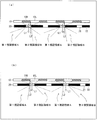
- the center line L1 of the opening 21 is shifted to the first direction side (left side of the drawing) with respect to the boundary line L2.
- the first viewing area A in the first direction is positioned on the horizontal direction side (the side closer to the display panel 10) with respect to the display panel 10, and the second viewing area B in the second direction is It is located on the front direction side (away from the display panel 10).
- the center line L1 of the opening 21 is shifted to the second direction side (right side of the drawing) with respect to the boundary line L2, the first viewing region in the first direction is displayed.
- A is located on the front direction side of the display panel 10
- the second viewing region B in the second direction is located on the horizontal direction side with respect to the display panel 10.
- FIG. 4 schematically shows a visual recognition region in the entire liquid crystal display device 1.
- 4A corresponds to FIG. 3A
- FIG. 4B corresponds to FIG. 3B.
- FIGS. 5 and 6 show the simulation results of the relationship between the deviation (offset) of the center line L1 of the opening 21 with respect to the boundary line L2 and the visual recognition area.
- the boundary line L2 as a reference, the left side (first direction side) of the paper surface is positive, and the right side of the paper surface (second direction side) is negative.
- the first viewing area A and the second viewing area B are arranged so as to be symmetric (laterally symmetric) in the first direction and the second direction.
- the first visual recognition area A is arranged on the horizontal direction side with respect to the liquid crystal display device 1
- the second visual recognition area B is on the front direction side of the liquid crystal display device 1.
- the offsets are set to ⁇ 50 ⁇ m and ⁇ 100 ⁇ m
- the first viewing area A is arranged on the front side of the liquid crystal display device 1
- the second viewing area B is on the horizontal side with respect to the liquid crystal display device 1.
- the liquid crystal display device 1 As described above, in the liquid crystal display device 1 according to the present embodiment, a viewing region that is asymmetric in the first direction and the second direction is formed, and therefore, the liquid crystal display device 1 is applied to many uses that cannot be achieved by a conventional display device. be able to. Below, the application example of the liquid crystal display device 1 is demonstrated.
- FIG. 8 shows a case where the liquid crystal display device 1 is applied to a car navigation system.
- the first visual recognition area A on the passenger seat side (first direction) or the second visual recognition area B on the driver seat side (second direction) is set to the liquid crystal display device 1.
- the driving safety can be improved as compared with the conventional dual-view display car navigation system. If the navigation screen is not used frequently, install the car navigation system closer to the passenger seat than the center of the passenger compartment, making it easier to view TV programs from the passenger seat and, if necessary, the driver's seat. The navigation screen can be seen from the side.
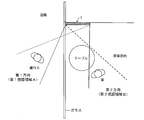
- FIG. 9 shows a case where the liquid crystal display device 1 is applied to a store (for example, a coffee shop).
- the liquid crystal display device 1 is installed near the corner window in the store, and displays a first image (for example, a coffee shop menu or advertisement) to passers-by outside the store, and at the same time, to customers in the store.
- a second image for example, a television program.
- the first visual recognition area A on the outside of the store can be brought close to the horizontal direction of the liquid crystal display device 1. It is possible to display an image appropriately for a person.
- the liquid crystal display device 1 can also be installed on the floor of an entrance / exit of a store (for example, a coffee shop). Specifically, the present liquid crystal display device 1 is embedded in the floor of the entrance / exit of the store so that the display surface faces upward, and displays the first image for the customer entering the store, and the customer leaving the store For the second image. In the present liquid crystal display device 1, the first visual recognition area A on the outside of the store (first direction side) can be brought close to the horizontal direction of the liquid crystal display device 1, so that customers who are away from the store are guided to the store. It is possible to provide information faster than customers who go out of the store. In such an application, the liquid crystal display device 1 can be installed on the ceiling.
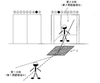
- FIG. 10 shows a case where the liquid crystal display device 1 is installed on a floor in front of an elevator in a store (for example, a department store). Specifically, this liquid crystal display device 1 is embedded in the floor of the elevator hall (hall) so that the display surface faces upward, and displays the first image for customers away from the elevator, A second image is displayed for the passengers getting off the elevator.
- a store for example, a department store.
- the first visual recognition area A in the direction away from the elevator can be brought closer to the horizontal direction of the liquid crystal display device 1
- the second visual recognition area B on the elevator side is Since it can approach the front direction of the liquid crystal display device 1, guidance for the elevator hall and the like are displayed for customers who are away from the elevator, and guidance for the floor and the like are displayed for customers who get off the elevator. be able to.
- this liquid crystal display device 1 can also be installed on a ceiling.
- the present liquid crystal display device 1 by controlling the display state of the image by the display control circuit, the same image is displayed in the first image display region 10L and the second image display region 10R, so that the viewing regions are mutually connected.
- the same image can be displayed in different first and second directions (single-screen display) ((b) in FIG. 2).
- the liquid crystal display device 1 there are cases where the first image and the second image are overlapped when viewed from the front direction (crosstalk). As one image.
- the configuration including the parallax barrier 20 as means for giving a viewing angle characteristic to an image from the display panel 10 (hereinafter, also referred to as “viewing angle control means”) has been described.
- the viewing angle control means that can be used for the form is not limited to the parallax barrier.
- the viewing angle control means it is possible to use a parallax barrier capable of electrically switching between viewing angle control effectiveness and invalidity.
- a parallax barrier when such a parallax barrier is used, when the parallax barrier effect is made effective, the openings 21 and the closing portions 22 are formed so as to be alternately arranged so that dual view display is performed and the effect of the parallax barrier is improved.
- the opening 21 is formed on the entire surface of the display panel 10 (total transmission), thereby enabling single view display. That is, according to the above configuration, dual view display and single view display can be switched between each other. Furthermore, since one image can be displayed using both the first image display area 10L and the second image display area 10R, an effect of increasing the resolution of the display screen can be obtained.
- a well-known method can be adopted as a method of generating dual view display images (right image and left image). For example, a method for creating a right image and a left image for an original still image or video corresponding to the size of the display screen, and separately transmitting the created image data (right image and left image) to the display panel, There is a method for transmitting pre-combined image data.
- the right image and the left image to be created are created as a single image or a combination of multiple images (for example, still images and still images, still images and moving images, moving images and moving images, still images) Picture and telop).
- one of the images is mirror-inverted so that one or more images look the same on the left and right at the stage of combining the images. This can be realized by arranging them at the same position.
- software for executing transmission processing Depending on the application, a right image and a left image that are partially the same image may be created.
- a display panel, and viewing angle control means in which openings that transmit light and closed portions that block light are alternately arranged,
- the viewing angle control means is configured such that the first image passes through the opening and is displayed in the first direction, and the second image passes through the opening and is displayed in the second direction.
- it may be configured to be provided on the front surface of the display panel.
- the center of each opening in the viewing angle control means is on the first direction side or the second side with respect to the boundary between the first pixel and the second pixel. It can also be set as the structure which has shifted
- the center of each opening in the viewing angle control means is shifted toward the first direction with respect to the boundary between the first pixel and the second pixel.
- the second image is displayed on the front side of the display panel.
- the center of each opening in the viewing angle control means is shifted toward the second direction with respect to the boundary between the first pixel and the second pixel.
- the first image can be displayed on the front side of the display panel.
- At least a part of the first image displayed in the first direction and at least a part of the second image displayed in the second direction are different from or identical to each other. You can also.
- first image and second image can be simultaneously viewed from different directions (first direction and second direction).
- images first image and second image
- the viewing angle control means can switch between valid and invalid viewing angle control, When the viewing angle control is effective, while the opening and the closing portion are alternately arranged, When the viewing angle control is invalid, the opening may be formed on the entire surface of the display panel.
- the display device of the present invention can be suitably used for various applications such as a car navigation system and a TV.
- SYMBOLS 1 Liquid crystal display device 10 Display panel 10L 1st image display area (1st pixel) 10R second image display area (second pixel) 20 Parallax barrier 21 Opening portion 22 Closing portion 30 Backlight L1 Center line L2 (of the opening portion 21 of the parallax barrier 20) Boundary line A (of the first image display region 10L and the second image display region 10R) A First viewing region B Second viewing area
Landscapes
- Physics & Mathematics (AREA)
- General Physics & Mathematics (AREA)
- Engineering & Computer Science (AREA)
- Theoretical Computer Science (AREA)
- Chemical & Material Sciences (AREA)
- Crystallography & Structural Chemistry (AREA)
- Nonlinear Science (AREA)
- Optics & Photonics (AREA)
- Marketing (AREA)
- Accounting & Taxation (AREA)
- Mathematical Physics (AREA)
- Business, Economics & Management (AREA)
- Computer Hardware Design (AREA)
- Liquid Crystal Display Device Control (AREA)
- Control Of Indicators Other Than Cathode Ray Tubes (AREA)
- Devices For Indicating Variable Information By Combining Individual Elements (AREA)
Abstract
複数の画像を複数の表示方向に同時に表示することができる液晶表示装置(1)であって、画像表示面に対して左右の斜め方向である第1方向および第2方向において、第1方向に表示される第1画像を視認できる第1視認領域(A)と、第2方向に表示される第2画像を視認できる第2視認領域(B)とが、画像表示面に対して左右非対称に配置されている。
Description
本発明は、同一の表示画面から、複数の表示方向それぞれに、互いに異なる複数の画像を同時に表示するマルチビュー表示を可能とする表示装置に関するものである。
液晶表示装置等の従来の表示装置では、表示パネルに対してどの視認方向から見ても同一の画像が観察されるシングルビュー表示モードが一般的である。近年、このシングルビュー表示モードに加えて、表示パネルに対して異なる視認方向から観察を行った場合、それぞれの視認方向に対して異なる画像を観察可能とする表示装置が提案されている。
特許文献1には、表示パネルに対して左方向から見た場合と右方向から見た場合とで異なる画像を観察可能とするデュアルビュー表示モード技術が開示されている。特許文献1におけるデュアルビュー表示の原理を、図11を参照して説明する。
図11に示す表示装置100は、表示パネル101の前面側(表示面側)に視差バリア(パララックスバリア)102が設けられ、表示パネル101の背面側にバックライト103が設けられている。表示パネル101には、第1画像を表示する画素101Lと、第2画像を表示する画素101Rとが交互に並んで配されている。
バックライト103から出射され、表示パネル101を通過する光は、視差バリア102によって特定の視野角を与えられ、左方向および右方向の少なくともいずれか一方向に出力される。例えば、図11の構成では、画素101Lを透過する光は液晶パネル101から見て右側(第1方向)へ出射され、画素101R(ハッチングで示す部分)を透過する光は液晶パネル101から見て左側(第2方向)へ出射される。これにより、画素101Lでは第1画像の表示を行い、画素101Rでは第2画像の表示を行うことができる。そして、表示パネル101に対して異なる視認方向から観察を行った場合に、それぞれの視認方向において、互いに異なる画像を観察することができる。
このような表示装置の具体的な用途の一例としては、カーナビゲーションシステムへの適用が挙げられる。これにより、運転席側および助手席側のそれぞれに、ナビゲーション画面およびテレビ番組等といった、互いに異なる画像を同時に表示することが可能となる。
ここで、従来のマルチビュー表示モードでは、第1方向に位置する観察者が第1画像を視認できる範囲(第1視認領域)と、第2方向に位置する観察者が第2画像を視認できる範囲(第2視認領域)とが同じ範囲(表示画面に対して左右対称)になるように設定されている。そのため、第1方向および第2方向から表示装置に対してほぼ同じ角度の範囲で視認するケースでは、それぞれの観察者にとって適正な表示が行われる。
しかしながら、第1方向および第2方向から表示装置に対して互いに異なる角度の範囲で視認するケースでは、それぞれの観察者にとって適正な表示が行われない。例えば、従来の表示装置をカーナビゲーションシステムに適用した場合に、当該表示装置を、運転席と助手席との中間位置よりも運転席側に取り付けた場合、運転席および助手席はクロストークが生じる(第1画像および第2画像が重なり合って見える)範囲(視認領域外)に位置してしまうおそれがある。このような場合、運転席側からはナビゲーション画面を適切に視認することができず、助手席側からもテレビ番組を適切に視認することができないという問題が生じる。
このように、従来の表示装置では、第1視認領域および第2視認領域が左右対称に配置されているため、その用途が限定されてしまう。
そこで、本発明では、マルチビュー表示を行う表示装置の用途を拡大し得る構成を提案する。
本発明に係る表示装置は、上記の課題を解決するために、
複数の画像を複数の表示方向に同時に表示することができる表示装置であって、
画像表示面に対して左右の斜め方向である第1方向および第2方向において、該第1方向に表示される第1画像を該第1方向側から視認できる第1視認領域と、該第2方向に表示される第2画像を該第2方向側から視認できる第2視認領域とが、画像表示面に対して左右非対称に配置されていることを特徴とする。
複数の画像を複数の表示方向に同時に表示することができる表示装置であって、
画像表示面に対して左右の斜め方向である第1方向および第2方向において、該第1方向に表示される第1画像を該第1方向側から視認できる第1視認領域と、該第2方向に表示される第2画像を該第2方向側から視認できる第2視認領域とが、画像表示面に対して左右非対称に配置されていることを特徴とする。
上記の構成によれば、上記第1視認領域と上記第2視認領域とが、画像表示面に対して左右非対称に配置される。そのため、本表示装置を、例えば、カーナビゲーションシステムに適用した場合、カーナビゲーションシステムを車両室内の中央よりも運転席側に設置しても、従来と同様、運転席側からは第1画像(ナビゲーション画面)を適切に視認することができ、助手席側からも第2画像(テレビ番組)を適切に視認することができる。また、カーナビゲーションシステムを運転席側に設置することにより、運転者によるカーナビゲーションシステムの操作性を向上させることができ、さらに、運転者が運転中にナビゲーション画面を確認する際の視線の動きを低減することもできる。よって、従来のデュアルビュー表示のカーナビゲーションシステムよりも、運転の安全性を高めることができる。
このように、上記第1視認領域と上記第2視認領域とを画像表示面に対して左右非対称に配置する構成を備えることにより、マルチビュー表示を行う表示装置の用途を拡大することができる。
以上のように、本発明に係る表示装置では、画像表示面に対して左右の斜め方向である第1方向および第2方向において、該第1方向に表示される第1画像を該第1方向側から視認できる第1視認領域と、該第2方向に表示される第2画像を該第2方向側から視認できる第2視認領域とが、画像表示面に対して左右非対称に配置されている構成である。これにより、マルチビュー表示を行う表示装置の用途を拡大することができる。
本発明の一実施の形態について図1に基づいて説明すると以下の通りである。まず、本実施の形態に係る液晶表示装置の構成について図1を参照して説明する。
図1に示す液晶表示装置1は、表示パネル10と、視差バリア20と、バックライト30と、各種駆動回路(データ信号線駆動回路、走査信号線駆動回路等;図示せず)と、表示制御回路(図示せず)を備えている。
表示パネル10は、周知の構成を採用することができる。例えば、表示パネル10は、ガラス等でなる絶縁性を有するアクティブマトリクス基板と、このアクティブマトリクス基板に対して所定の間隔で対向するガラス等でなる光透過性を有する対向基板と、アクティブマトリクス基板と対向基板との間に挟持された液晶層とで構成される。液晶層としては、種々のタイプの液晶層を用いることができる。
表示パネル10には、列方向に延伸するデータ信号線、行方向に延伸する走査信号線および容量配線、行および列方向に並べられた画素(後述の第1画素および第2画素)が設けられている。各種信号線はアクティブマトリクス基板に設けられている。
各画素の構造は同一の構成であり、1つの画素に対応して、少なくとも1つの画素電極が設けられ、データ信号線と走査信号線と容量配線とがそれぞれ1本ずつ設けられている。各画素では、アクティブマトリクス基板において、画素電極が、走査信号線に接続されたトランジスタ(TFT)を介してデータ信号線に接続されており、対向基板に設けられた対向電極との間に液晶容量が形成されている。
各画素に設けられたトランジスタは、ドレイン電極が画素電極に接続され、ソース電極がデータ信号線に接続され、ゲート電極が走査信号線に接続されている。これにより、トランジスタは、走査信号線から供給される走査信号(ゲート信号)によってオン/オフ制御され、データ信号線に供給されるデータ信号に応じた電圧が液晶層に印加され、トランジスタがオフ時に、該電圧が保持される構成となっている。
表示制御回路は、タイミングコントローラから供給されるタイミング制御信号に基づいて画像表示タイミングを検知して、外部から入力された表示データおよび同期信号に基づいて、表示パネル10に画像を表示するための表示制御信号を生成する。そして、生成した表示制御信号を各種駆動回路に供給して各種駆動回路の動作を制御する。
走査信号線駆動回路は、表示制御回路から出力される表示制御信号に基づいて、走査信号(ゲート信号)を、各走査信号線に順次供給する。これにより、走査信号が供給された走査信号線に接続されたトランジスタがオン状態になる。
データ信号線駆動回路は、表示制御信号に基づいて、データ信号をデータ信号線に供給する。これにより、オン状態になっているトランジスタを介して液晶層にデータ信号に応じた電圧が印加されて画像情報が書き込まれる。
バックライト30は、表示パネル10の背面側に配置され、表示パネル10に対して表示光を入射する。なお、バックライト30は、液晶表示装置1に含まれるものであってもよく、あるいは、液晶表示装置1に対して外付けされるものであってもよい。
視差バリア20は、表示パネル10の前面側(観察者に近い側)に、視差バリア20の表面と表示パネル10の表示面とが互いに平行になるように、樹脂材料により貼り合わされている。視差バリア20は、表示パネル10から出力される表示画像(第1画像、第2画像)を通過させる開口部21と、該表示画像を遮断する閉口部22とを備えている。開口部21および閉口部22は、表示パネル10の画素に対応して、交互に並んで形成されている。
続いて、液晶表示装置1におけるデュアルビュー表示の表示原理について説明する。なお、液晶表示装置1は、複数の画像を複数の表示方向に同時に表示する機能を有するものであればデュアルビュー方式の液晶表示装置に限定されず、マルチビュー表示方式の液晶表示装置であっても良い。また、デュアルビュー方式またはマルチビュー表示方式は、液晶表示装置以外でも実現可能であるため、例えば有機ELパネルやCRT等を用いることもできる。以下では、図2の(a)および(b)に示すデュアルビュー表示について具体的に説明する。
図2の(a)および(b)は、液晶表示装置1の画面表示を説明するための模式図である。液晶表示装置1は、図2の(a)に示すように、液晶表示装置1から第1方向に向けて第1画像を表示すると同時に、液晶表示装置1から、第1方向とは異なる第2方向に向けて第1画像とは異なる第2画像を表示する機能、つまり、互いに異なる方向へ、互いに異なる2つの画像を同時に表示する機能を有する。なお、液晶表示装置1は、同時に表示する第1画像および第2画像のそれぞれの一部を、互いに同一にするあるいは異ならせる機能を有していてもよい。
上記「第1方向」および「第2方向」は、それぞれ、液晶表示装置1の表示方向を表す。また、ここでは、説明の便宜上、液晶表示装置1(表示パネル10)から見て右斜め前方の方向を第1方向、液晶表示装置1(表示パネル10)から見て左斜め前方の方向を第2方向とする。また、ここでは、第1方向に対する画像を第1画像、第2方向に対する画像を第2画像と称する。さらに、「正面方向」とは、第1方向と第2方向との中間の方向を表す。すなわち、「正面方向」とは、液晶表示装置1の2つの表示方向の間の方向ということもできる。また、正面方向に対する画像を正面画像と称する。
また、液晶表示装置1が備える表示制御回路(図示せず)により、画像を単画面表示処理すれば、液晶表示装置1は、図2の(b)に示すように、第1方向、第2方向、および正面方向の、いずれの方向からも同一の画像を視認可能であるように表示させることもできる。本明細書において、この表示を単画面表示と称する。
ここで、液晶表示装置1の構造について、より詳細に説明する。液晶表示装置1は、上述したように、バックライト30と、表示パネル10と、視差バリア20とがこの順に重ね合わされた構造を有している(図1参照)。バックライト30は、照明装置であり、表示パネル10に対して光を照射する。表示パネル10は、バックライト30からの光を透過・遮光させることで、画像を作り出す。視差バリア20は、表示パネル10により作り出された画像に、視野角特性を与える。なお、表示パネル10には、カラーフィルタ(図示しない)を設け、カラー表示が可能な構成としてもよい。
表示パネル10は、図1に示すように、第1画像を表示する第1画像表示領域10Lと、第2画像を表示する第2画像表示領域10Rとが、交互に並んで短冊状(ストライプ状)に構成されている。第1画像表示領域10Lおよび第2画像表示領域10Rは、それぞれ1つの画素(第1画素および第2画素)に対応する。また、視差バリア20は、表示パネル10の表示画像(第1画像、第2画像)を通過させる開口部21と、表示パネル10の表示画像を遮断する閉口部22とが、交互に並んで形成されている。
このような構造を有する表示パネル10と視差バリア20とを重ね合わせることによって、第1画像表示領域10Lに表示された第1画像は、開口部21を通過して、第1方向に位置する観察者から視認される。一方、第2画像表示領域10Rに表示された第2画像は閉口部22に遮断されるので、第1方向に位置する観察者からは視認されない。
また、第2画像表示領域10Rに表示された第2画像は、開口部21を通過して、第2方向に位置する観察者から視認される。一方、第1画像表示領域10Lに表示された第1画像は閉口部22に遮断されるので、第2方向に位置する観察者からは視認されない。
このようにして液晶表示装置1は、第1方向と第2方向とのそれぞれに、第1画像と第2画像とを同時に表示することが可能となる。
ここで、本実施の形態に係る液晶表示装置1では、第1方向に表示される第1画像を視認できる第1視認領域と、第2方向に表示される第2画像を視認できる第2視認領域とが、画像表示面(液晶表示装置1)に対して左右非対称に配置されるように構成されている。なお、「視認領域」とは、一方向に表示される画像のみを適正に視認できる領域(範囲)であって、複数の画像が重なって見える(クロストークが生じる)領域を除いた領域をいう。
具体的には、図3の(a)および(b)に示すように、視差バリア20の開口部21の中心線L1が、第1画像表示領域10L(第1画素)および第2画像表示領域10R(第2画素)の境界線L2に対して、第1方向側または第2方向側にずれた状態で、表示パネル10と視差バリア20とが重ね合わされている。図3の(a)では、開口部21の中心線L1が、境界線L2に対して第1方向側(紙面左側)にずれている。これにより、第1方向の第1視認領域Aは、表示パネル10に対して水平方向側(表示パネル10に近い方)に位置し、第2方向の第2視認領域Bは、表示パネル10の正面方向側(表示パネル10から遠い方)に位置する。これに対して、図3の(b)では、開口部21の中心線L1が、境界線L2に対して第2方向側(紙面右側)にずれているため、第1方向の第1視認領域Aは、表示パネル10の正面方向側に位置し、第2方向の第2視認領域Bは、表示パネル10に対して水平方向側に位置する。
図4には、液晶表示装置1全体における視認領域を模式的に示している。図4の(a)は、図3の(a)に対応しており、図4の(b)は図3の(b)に対応している。
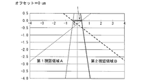
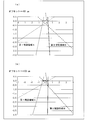
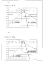
ここで、境界線L2に対する開口部21の中心線L1のずれ(オフセット)と視認領域との関係についてシミュレーションした結果を図5および図6に示す。なお、境界線L2を基準として紙面左側(第1方向側)を正、紙面右側(第2方向側)を負とする。図5は、オフセット=0の状態(従来の表示装置に相当)を示し、図6の(a)は、オフセット=+50umの状態を示し、図6の(b)は、オフセット=+100umの状態を示している。また、図7の(a)は、オフセット=-50umの状態を示し、図7の(b)は、オフセット=-100umの状態を示している。
オフセット=0の状態(図5)では、第1視認領域Aおよび第2視認領域Bが、第1方向および第2方向に対称(左右対称)となるように配置される。これに対して、オフセット=+50um、+100umに設定することにより、第1視認領域Aは液晶表示装置1に対して水平方向側に配置され、第2視認領域Bは液晶表示装置1の正面方向側に配置される(図6の(a)および(b))。また、オフセット=-50um、-100umに設定することにより、第1視認領域Aは液晶表示装置1の正面方向側に配置され、第2視認領域Bは液晶表示装置1に対して水平方向側に配置される(図7の(a)および(b))。なお、第1視認領域Aおよび第2視認領域Bの位置とオフセット値の関係は、表示パネル10および画素のサイズ、視差バリア20の設計値などに応じて変化するため、液晶表示装置1の用途に応じてオフセットの値を設定することが好ましい。
このように、本実施の形態に係る液晶表示装置1では、第1方向および第2方向に非対称となる視認領域が形成されるため、従来の表示装置ではなし得なかった多くの用途に適用することができる。
以下では、液晶表示装置1の適用例について説明する。
以下では、液晶表示装置1の適用例について説明する。
(適用例1)
図8は、液晶表示装置1をカーナビゲーションシステムに適用した場合を示している。本液晶表示装置1を搭載したカーナビゲーションシステムでは、助手席側(第1方向)の第1視認領域Aまたは運転席側(第2方向)の第2視認領域Bを、液晶表示装置1に対して正面方向側に配置することができる。そのため、例えばカーナビゲーションシステムを車両室内の中央よりも運転席側に設置しても、従来と同様、運転席側からはナビゲーション画面を適切に視認することができ、助手席側からもテレビ番組を適切に視認することができる。また、カーナビゲーションシステムを運転席側に設置することにより、運転者によるカーナビゲーションシステムの操作性を向上させることができ、さらに、運転者が運転中にナビゲーション画面を確認する際の視線の動きを低減することもできる。よって、従来のデュアルビュー表示のカーナビゲーションシステムよりも、運転の安全性を高めることができる。また、ナビゲーション画面の使用頻度が低い場合等は、カーナビゲーションシステムを車両室内の中央よりも助手席側に設置することにより、助手席側からテレビ番組をより見易くするとともに、必要に応じて運転席側からはナビゲーション画面を視認することができる。
図8は、液晶表示装置1をカーナビゲーションシステムに適用した場合を示している。本液晶表示装置1を搭載したカーナビゲーションシステムでは、助手席側(第1方向)の第1視認領域Aまたは運転席側(第2方向)の第2視認領域Bを、液晶表示装置1に対して正面方向側に配置することができる。そのため、例えばカーナビゲーションシステムを車両室内の中央よりも運転席側に設置しても、従来と同様、運転席側からはナビゲーション画面を適切に視認することができ、助手席側からもテレビ番組を適切に視認することができる。また、カーナビゲーションシステムを運転席側に設置することにより、運転者によるカーナビゲーションシステムの操作性を向上させることができ、さらに、運転者が運転中にナビゲーション画面を確認する際の視線の動きを低減することもできる。よって、従来のデュアルビュー表示のカーナビゲーションシステムよりも、運転の安全性を高めることができる。また、ナビゲーション画面の使用頻度が低い場合等は、カーナビゲーションシステムを車両室内の中央よりも助手席側に設置することにより、助手席側からテレビ番組をより見易くするとともに、必要に応じて運転席側からはナビゲーション画面を視認することができる。
(適用例2)
図9は、液晶表示装置1を店舗(例えば喫茶店)に適用した場合を示している。本液晶表示装置1は、店内のコーナー部分の窓際に設置され、店外の通行人に対して第1画像(例えば、喫茶店のメニューや宣伝広告など)を表示し、同時に、店内の客に対して第2画像(例えば、テレビ番組など)を表示する。本液晶表示装置1では、店外側(第1方向側)の第1視認領域Aを液晶表示装置1の水平方向に近づけることができるため、店外の通行人(特に、店から離れている通行人)に対しても適切に画像を表示することができる。
図9は、液晶表示装置1を店舗(例えば喫茶店)に適用した場合を示している。本液晶表示装置1は、店内のコーナー部分の窓際に設置され、店外の通行人に対して第1画像(例えば、喫茶店のメニューや宣伝広告など)を表示し、同時に、店内の客に対して第2画像(例えば、テレビ番組など)を表示する。本液晶表示装置1では、店外側(第1方向側)の第1視認領域Aを液晶表示装置1の水平方向に近づけることができるため、店外の通行人(特に、店から離れている通行人)に対しても適切に画像を表示することができる。
(適用例3)
液晶表示装置1を店舗(例えば喫茶店)の出入り口の床に設置することもできる。具体的には、本液晶表示装置1は、店内の出入り口の床に、表示面が上向きになるように埋め込まれており、店内に入る客に対して第1画像を表示し、店内から出る客に対して第2画像を表示する。本液晶表示装置1では、店外側(第1方向側)の第1視認領域Aを液晶表示装置1の水平方向に近づけることができるため、店から離れている客に対して、店内への案内を表示するなど、店内から外へ出る客よりも早く情報を提供することができる。このような用途では、本液晶表示装置1を、天井に設置することもできる。
液晶表示装置1を店舗(例えば喫茶店)の出入り口の床に設置することもできる。具体的には、本液晶表示装置1は、店内の出入り口の床に、表示面が上向きになるように埋め込まれており、店内に入る客に対して第1画像を表示し、店内から出る客に対して第2画像を表示する。本液晶表示装置1では、店外側(第1方向側)の第1視認領域Aを液晶表示装置1の水平方向に近づけることができるため、店から離れている客に対して、店内への案内を表示するなど、店内から外へ出る客よりも早く情報を提供することができる。このような用途では、本液晶表示装置1を、天井に設置することもできる。
(適用例4)
図10は、液晶表示装置1を店舗(例えばデパート)内のエレベータ前の床に設置した場合を示している。具体的には、本液晶表示装置1は、エレベータ乗り場(ホール)の床に、表示面が上向きになるように埋め込まれており、エレベータから離れている客に対して第1画像を表示し、エレベータから降りる客に対して第2画像を表示する。本液晶表示装置1では、エレベータから離れる方向(第1方向)の第1視認領域Aを液晶表示装置1の水平方向に近づけることができ、エレベータ側(第2方向)の第2視認領域Bを液晶表示装置1の正面方向に近づけることができるため、エレベータから離れている客に対して、エレベータ乗り場の案内等などを表示するとともに、エレベータから降りる客に対して、フロアの案内等を表示することができる。なお、本液晶表示装置1を、天井に設置することもできる。
図10は、液晶表示装置1を店舗(例えばデパート)内のエレベータ前の床に設置した場合を示している。具体的には、本液晶表示装置1は、エレベータ乗り場(ホール)の床に、表示面が上向きになるように埋め込まれており、エレベータから離れている客に対して第1画像を表示し、エレベータから降りる客に対して第2画像を表示する。本液晶表示装置1では、エレベータから離れる方向(第1方向)の第1視認領域Aを液晶表示装置1の水平方向に近づけることができ、エレベータ側(第2方向)の第2視認領域Bを液晶表示装置1の正面方向に近づけることができるため、エレベータから離れている客に対して、エレベータ乗り場の案内等などを表示するとともに、エレベータから降りる客に対して、フロアの案内等を表示することができる。なお、本液晶表示装置1を、天井に設置することもできる。
以上のように、本液晶表示装置1は、第1方向に位置する観察者が第1画像を視認できる範囲(第1視認領域A)と、第2方向に位置する観察者が第2画像を視認できる範囲(第2視認領域B)とを異ならせる(非対称とする)ことができるため、デュアルビュー表示を行う液晶表示装置を様々な用途に利用することができる。
なお、本液晶表示装置1では、表示制御回路によって画像の表示状態を制御することにより、第1画像表示領域10Lおよび第2画像表示領域10Rに同一の画像を表示させることにより、視認領域が互いに異なる第1方向および第2方向に、同一の画像を表示させることもできる(単画面表示)(図2の(b))。
また、液晶表示装置1の構成によっては、正面方向から視認した際に、第1画像と第2画像とが重なって視認される場合(クロストーク)があるが、単画面表示の際には1つの画像として視認される。
また、本実施の形態では、表示パネル10からの画像に視野角特性を与える手段(以下、「視野角制御手段」ともいう)として視差バリア20を備える構成について説明したが、本発明の実施の形態に用いることが可能な視野角制御手段は視差バリアに限定されるものではない。例えば、視野角制御手段としては、視野角制御の有効および無効を、電気的に相互に切り替え可能な視差バリアを用いることができる。このような視差バリアを用いれば、視差バリアの効果を有効にした場合は、開口部21および閉口部22が交互に並ぶように形成されることにより、デュアルビュー表示を行い、視差バリアの効果を無効にした場合は、開口部21が表示パネル10に対して全面に形成されることにより(全透過)、シングルビュー表示を行うことが可能となる。すなわち、上記構成によれば、デュアルビュー表示とシングルビュー表示とを相互に切り替えることができる。さらに、第1画像表示領域10Lおよび第2画像表示領域10Rの両方を用いて、1つの画像を表示できるので、表示画面の解像度を上げる効果も得られる。
また、デュアルビュー表示の画像(右用画像および左用画像)の生成方法は周知の方法を採用することができる。例えば、表示画面の大きさに対応する元の静止画あるいは動画について右用画像および左用画像を作成し、作成した画像データ(右用画像および左用画像)を別々に表示パネルに送信する方法や、予め合成した画像データを送信する方法がある。なお、作成する右用画像および左用画像は、1枚の画像として作成する場合や、複数の画像を組み合わせて作成する場合(例えば、静止画と静止画、静止画と動画、動画と動画、静止画とテロップなど)がある。また、右用画像および左用画像のそれぞれの一部を同一画像にする場合は、画像を組み合わせる段階で、1つ以上の画像を左右同じに見えるように、一方の画像をミラー反転させ、左右で同一の位置に配置することにより実現できる。なお、作成した画像データ(右用画像および左用画像)を別々に表示パネルに送信する方法では、上記のように一方の画像を予めミラー反転させる構成の他、例えば、送信処理を実行するソフト(アプリケーション)により、一部が同一画像となる右用画像および左用画像を作成する構成とすることもできる。
本発明の実施の形態に係る表示装置では、
表示パネルと、光を通過する開口部および光を遮断する閉口部が交互に並んで配されている視野角制御手段とを備え、
上記表示パネルには、上記第1方向に上記第1画像を表示する第1画素と、上記第2方向に上記第2画像を表示する第2画素とが交互に並んで配されており、
上記視野角制御手段は、上記第1画像が上記開口部を通過して上記第1方向に表示されるとともに、上記第2画像が上記開口部を通過して上記第2方向に表示されるように、上記表示パネルの前面に設けられている構成とすることもできる。
表示パネルと、光を通過する開口部および光を遮断する閉口部が交互に並んで配されている視野角制御手段とを備え、
上記表示パネルには、上記第1方向に上記第1画像を表示する第1画素と、上記第2方向に上記第2画像を表示する第2画素とが交互に並んで配されており、
上記視野角制御手段は、上記第1画像が上記開口部を通過して上記第1方向に表示されるとともに、上記第2画像が上記開口部を通過して上記第2方向に表示されるように、上記表示パネルの前面に設けられている構成とすることもできる。
上記の構成によれば、簡易な構成によりデュアルビュー表示が可能となる。
本発明の実施の形態に係る表示装置では、
上記表示パネルを正面方向から見たときに、上記視野角制御手段における上記各開口部の中心が、上記第1画素および上記第2画素の境界に対して、上記第1方向側または上記第2方向側にずれている構成とすることもできる。
上記表示パネルを正面方向から見たときに、上記視野角制御手段における上記各開口部の中心が、上記第1画素および上記第2画素の境界に対して、上記第1方向側または上記第2方向側にずれている構成とすることもできる。
上記の構成によれば、簡易な構成により上記第1視認領域と上記第2視認領域とを画像表示面に対して左右非対称に配置する構成を実現することができる。
本発明の実施の形態に係る表示装置では、
上記表示パネルを正面方向から見たときに、上記視野角制御手段における上記各開口部の中心が、上記第1画素および上記第2画素の境界に対して、上記第1方向側にずれている場合は、上記表示パネルの正面側に上記第2画像が表示される一方、
上記表示パネルを正面方向から見たときに、上記視野角制御手段における上記各開口部の中心が、上記第1画素および上記第2画素の境界に対して、上記第2方向側にずれている場合は、上記表示パネルの正面側に上記第1画像が表示される構成とすることもできる。
上記表示パネルを正面方向から見たときに、上記視野角制御手段における上記各開口部の中心が、上記第1画素および上記第2画素の境界に対して、上記第1方向側にずれている場合は、上記表示パネルの正面側に上記第2画像が表示される一方、
上記表示パネルを正面方向から見たときに、上記視野角制御手段における上記各開口部の中心が、上記第1画素および上記第2画素の境界に対して、上記第2方向側にずれている場合は、上記表示パネルの正面側に上記第1画像が表示される構成とすることもできる。
本発明の実施の形態に係る表示装置では、
上記第1方向に表示される上記第1画像の少なくとも一部と、上記第2方向に表示される上記第2画像の少なくとも一部とが、互いに異なっているあるいは互いに同一である構成とすることもできる。
上記第1方向に表示される上記第1画像の少なくとも一部と、上記第2方向に表示される上記第2画像の少なくとも一部とが、互いに異なっているあるいは互いに同一である構成とすることもできる。
上記の構成によれば、異なる方向(第1方向および第2方向)から異なる画像(第1画像および第2画像)を同時に視認することができる。また、異なる方向(第1方向および第2方向)から、一部のみが同一あるいは異なる画像(第1画像および第2画像)を同時に視認することもできる。
本発明の実施の形態に係る表示装置では、
上記視野角制御手段は、視野角制御の有効および無効を相互に切り替え可能であり、
上記視野角制御が有効のときは、上記開口部および上記閉口部が交互に並ぶように形成される一方、
上記視野角制御が無効のときは、上記開口部が上記表示パネルに対して全面に形成される構成とすることもできる。
上記視野角制御手段は、視野角制御の有効および無効を相互に切り替え可能であり、
上記視野角制御が有効のときは、上記開口部および上記閉口部が交互に並ぶように形成される一方、
上記視野角制御が無効のときは、上記開口部が上記表示パネルに対して全面に形成される構成とすることもできる。
これにより、デュアルビュー表示とシングルビュー表示とを相互に切り替えることができる。
本発明は上述した各実施形態に限定されるものではなく、請求項に示した範囲で種々の変更が可能であり、異なる実施形態にそれぞれ開示された技術的手段を適宜組み合わせて得られる実施形態についても本発明の技術的範囲に含まれる。
本発明の表示装置は、カーナビゲーションシステム、TV等の各種用途に好適に用いることができる。
1 液晶表示装置
10 表示パネル
10L 第1画像表示領域(第1画素)
10R 第2画像表示領域(第2画素)
20 視差バリア
21 開口部
22 閉口部
30 バックライト
L1 (視差バリア20の開口部21の)中心線
L2 (第1画像表示領域10Lおよび第2画像表示領域10Rの)境界線
A 第1視認領域
B 第2視認領域
10 表示パネル
10L 第1画像表示領域(第1画素)
10R 第2画像表示領域(第2画素)
20 視差バリア
21 開口部
22 閉口部
30 バックライト
L1 (視差バリア20の開口部21の)中心線
L2 (第1画像表示領域10Lおよび第2画像表示領域10Rの)境界線
A 第1視認領域
B 第2視認領域
Claims (6)
- 複数の画像を複数の表示方向に同時に表示することができる表示装置であって、
画像表示面に対して左右の斜め方向である第1方向および第2方向において、該第1方向に表示される第1画像を該第1方向側から視認できる第1視認領域と、該第2方向に表示される第2画像を該第2方向側から視認できる第2視認領域とが、画像表示面に対して左右非対称に配置されていることを特徴とする表示装置。 - 表示パネルと、光を通過する開口部および光を遮断する閉口部が交互に並んで配されている視野角制御手段とを備え、
上記表示パネルには、上記第1方向に上記第1画像を表示する第1画素と、上記第2方向に上記第2画像を表示する第2画素とが交互に並んで配されており、
上記視野角制御手段は、上記第1画像が上記開口部を通過して上記第1方向に表示されるとともに、上記第2画像が上記開口部を通過して上記第2方向に表示されるように、上記表示パネルの前面に設けられていることを特徴とする請求項1に記載の表示装置。 - 上記表示パネルを正面方向から見たときに、上記視野角制御手段における上記各開口部の中心が、上記第1画素および上記第2画素の境界に対して、上記第1方向側または上記第2方向側にずれていることを特徴とする請求項2に記載の表示装置。
- 上記表示パネルを正面方向から見たときに、上記視野角制御手段における上記各開口部の中心が、上記第1画素および上記第2画素の境界に対して、上記第1方向側にずれている場合は、上記表示パネルの正面側に上記第2画像が表示される一方、
上記表示パネルを正面方向から見たときに、上記視野角制御手段における上記各開口部の中心が、上記第1画素および上記第2画素の境界に対して、上記第2方向側にずれている場合は、上記表示パネルの正面側に上記第1画像が表示されることを特徴とする請求項3に記載の表示装置。 - 上記第1方向に表示される上記第1画像の少なくとも一部と、上記第2方向に表示される上記第2画像の少なくとも一部とが、互いに異なっているあるいは互いに同一であることを特徴とする請求項1に記載の表示装置。
- 上記視野角制御手段は、視野角制御の有効および無効を相互に切り替え可能であり、
上記視野角制御が有効のときは、上記開口部および上記閉口部が交互に並ぶように形成される一方、
上記視野角制御が無効のときは、上記開口部が上記表示パネルに対して全面に形成されることを特徴とする請求項2に記載の表示装置。
Applications Claiming Priority (2)
| Application Number | Priority Date | Filing Date | Title |
|---|---|---|---|
| JP2011-057255 | 2011-03-15 | ||
| JP2011057255 | 2011-03-15 |
Publications (1)
| Publication Number | Publication Date |
|---|---|
| WO2012124600A1 true WO2012124600A1 (ja) | 2012-09-20 |
Family
ID=46830673
Family Applications (1)
| Application Number | Title | Priority Date | Filing Date |
|---|---|---|---|
| PCT/JP2012/055972 Ceased WO2012124600A1 (ja) | 2011-03-15 | 2012-03-08 | 表示装置 |
Country Status (1)
| Country | Link |
|---|---|
| WO (1) | WO2012124600A1 (ja) |
Cited By (4)
| Publication number | Priority date | Publication date | Assignee | Title |
|---|---|---|---|---|
| CN104064658A (zh) * | 2014-07-05 | 2014-09-24 | 福州大学 | 一种led显示屏及其3d显示装置 |
| JP2015046671A (ja) * | 2013-08-27 | 2015-03-12 | 三菱電機株式会社 | 携帯端末装置 |
| JP2015046669A (ja) * | 2013-08-27 | 2015-03-12 | 三菱電機株式会社 | 携帯端末装置 |
| CN113602924A (zh) * | 2020-05-04 | 2021-11-05 | 奥的斯电梯公司 | 向不同个体提供不同信息的电梯系统显示器 |
Citations (8)
| Publication number | Priority date | Publication date | Assignee | Title |
|---|---|---|---|---|
| JP2005078076A (ja) * | 2003-08-30 | 2005-03-24 | Sharp Corp | マルチプルビュー方向ディスプレイ |
| JP2005099787A (ja) * | 2003-08-30 | 2005-04-14 | Sharp Corp | ディスプレイおよびリフレクタ |
| JP2006184860A (ja) * | 2004-11-30 | 2006-07-13 | Fujitsu Ten Ltd | マルチビュー表示装置 |
| JP2006184859A (ja) * | 2004-11-30 | 2006-07-13 | Fujitsu Ten Ltd | 表示制御装置、及び表示装置 |
| JP2007298838A (ja) * | 2006-05-01 | 2007-11-15 | Sharp Corp | 表示装置、および、これを備える情報処理装置並びに通信装置 |
| WO2008126283A1 (ja) * | 2007-03-30 | 2008-10-23 | Pioneer Corporation | 画像表示装置 |
| JP2009500737A (ja) * | 2005-07-08 | 2009-01-08 | シャープ株式会社 | マルチビュー表示システム |
| JP2009250994A (ja) * | 2008-04-01 | 2009-10-29 | Epson Imaging Devices Corp | 電気光学装置 |
-
2012
- 2012-03-08 WO PCT/JP2012/055972 patent/WO2012124600A1/ja not_active Ceased
Patent Citations (8)
| Publication number | Priority date | Publication date | Assignee | Title |
|---|---|---|---|---|
| JP2005078076A (ja) * | 2003-08-30 | 2005-03-24 | Sharp Corp | マルチプルビュー方向ディスプレイ |
| JP2005099787A (ja) * | 2003-08-30 | 2005-04-14 | Sharp Corp | ディスプレイおよびリフレクタ |
| JP2006184860A (ja) * | 2004-11-30 | 2006-07-13 | Fujitsu Ten Ltd | マルチビュー表示装置 |
| JP2006184859A (ja) * | 2004-11-30 | 2006-07-13 | Fujitsu Ten Ltd | 表示制御装置、及び表示装置 |
| JP2009500737A (ja) * | 2005-07-08 | 2009-01-08 | シャープ株式会社 | マルチビュー表示システム |
| JP2007298838A (ja) * | 2006-05-01 | 2007-11-15 | Sharp Corp | 表示装置、および、これを備える情報処理装置並びに通信装置 |
| WO2008126283A1 (ja) * | 2007-03-30 | 2008-10-23 | Pioneer Corporation | 画像表示装置 |
| JP2009250994A (ja) * | 2008-04-01 | 2009-10-29 | Epson Imaging Devices Corp | 電気光学装置 |
Cited By (6)
| Publication number | Priority date | Publication date | Assignee | Title |
|---|---|---|---|---|
| JP2015046671A (ja) * | 2013-08-27 | 2015-03-12 | 三菱電機株式会社 | 携帯端末装置 |
| JP2015046669A (ja) * | 2013-08-27 | 2015-03-12 | 三菱電機株式会社 | 携帯端末装置 |
| CN104064658A (zh) * | 2014-07-05 | 2014-09-24 | 福州大学 | 一种led显示屏及其3d显示装置 |
| CN113602924A (zh) * | 2020-05-04 | 2021-11-05 | 奥的斯电梯公司 | 向不同个体提供不同信息的电梯系统显示器 |
| EP3907167A1 (en) * | 2020-05-04 | 2021-11-10 | Otis Elevator Company | Elevator system display that provides different information to different individuals |
| CN113602924B (zh) * | 2020-05-04 | 2023-04-07 | 奥的斯电梯公司 | 向不同个体提供不同信息的电梯系统显示器 |
Similar Documents
| Publication | Publication Date | Title |
|---|---|---|
| US9874770B2 (en) | Display device | |
| CN103517053B (zh) | 视差栅栏型立体图像显示设备 | |
| JP4530408B2 (ja) | マルチプルビュー方向ディスプレイ | |
| JP5722106B2 (ja) | 表示パネル、表示装置および電子機器 | |
| JP5969699B2 (ja) | 立体表示装置 | |
| CN100474359C (zh) | 显示器件 | |
| CN103325322A (zh) | 显示设备和电子设备 | |
| JP4200056B2 (ja) | 表示装置 | |
| US20180067328A1 (en) | Display device | |
| WO2017198027A1 (zh) | 显示面板组件、显示装置及其驱动方法 | |
| CN105372822A (zh) | 切换屏障和具有该切换屏障的3d显示装置 | |
| CN100501500C (zh) | 立体显示设备及其驱动方法 | |
| WO2015060011A1 (ja) | 立体表示装置 | |
| WO2012124600A1 (ja) | 表示装置 | |
| CN101263545B (zh) | 显示装置 | |
| US20130181968A1 (en) | Drive circuit of display device, display device, and method of driving display device | |
| JP2008185964A (ja) | 表示装置 | |
| JP6009648B2 (ja) | 立体表示装置 | |
| KR20130064325A (ko) | 입체 영상 표시용 패럴랙스 배리어 및 이를 이용한 표시 장치 | |
| US20140022241A1 (en) | Display apparatus and method based on symmetrically spb | |
| JP6698768B2 (ja) | バリアパネルを含む立体映像表示装置 | |
| KR101282290B1 (ko) | 3차원 영상표시장치 | |
| JP2006330018A (ja) | マルチ視野ディスプレイ | |
| KR20180037982A (ko) | 몰입감을 향상시킨 입체영상장치 및 이를 이용한 게임장치 | |
| JP3634486B2 (ja) | 立体映像の表示方法 |
Legal Events
| Date | Code | Title | Description |
|---|---|---|---|
| 121 | Ep: the epo has been informed by wipo that ep was designated in this application |
Ref document number: 12758323 Country of ref document: EP Kind code of ref document: A1 |
|
| NENP | Non-entry into the national phase |
Ref country code: DE |
|
| 122 | Ep: pct application non-entry in european phase |
Ref document number: 12758323 Country of ref document: EP Kind code of ref document: A1 |
|
| NENP | Non-entry into the national phase |
Ref country code: JP |