WO2012124554A1 - 電力貯蔵装置並びにそれを備えた電源装置及び移動体 - Google Patents
電力貯蔵装置並びにそれを備えた電源装置及び移動体 Download PDFInfo
- Publication number
- WO2012124554A1 WO2012124554A1 PCT/JP2012/055741 JP2012055741W WO2012124554A1 WO 2012124554 A1 WO2012124554 A1 WO 2012124554A1 JP 2012055741 W JP2012055741 W JP 2012055741W WO 2012124554 A1 WO2012124554 A1 WO 2012124554A1
- Authority
- WO
- WIPO (PCT)
- Prior art keywords
- battery
- storage device
- power
- power storage
- equalization
- Prior art date
- Legal status (The legal status is an assumption and is not a legal conclusion. Google has not performed a legal analysis and makes no representation as to the accuracy of the status listed.)
- Ceased
Links
Images




Classifications
-
- H—ELECTRICITY
- H01—ELECTRIC ELEMENTS
- H01M—PROCESSES OR MEANS, e.g. BATTERIES, FOR THE DIRECT CONVERSION OF CHEMICAL ENERGY INTO ELECTRICAL ENERGY
- H01M10/00—Secondary cells; Manufacture thereof
- H01M10/42—Methods or arrangements for servicing or maintenance of secondary cells or secondary half-cells
- H01M10/44—Methods for charging or discharging
- H01M10/441—Methods for charging or discharging for several batteries or cells simultaneously or sequentially
-
- H—ELECTRICITY
- H02—GENERATION; CONVERSION OR DISTRIBUTION OF ELECTRIC POWER
- H02J—ELECTRIC POWER NETWORKS; CIRCUIT ARRANGEMENTS OR SYSTEMS FOR SUPPLYING OR DISTRIBUTING ELECTRIC POWER; SYSTEMS FOR STORING ELECTRIC ENERGY
- H02J7/00—Circuit arrangements for charging or discharging batteries or for supplying loads from batteries
- H02J7/34—Parallel operation in networks using both storage and other DC sources, e.g. providing buffering
- H02J7/342—The other DC source being a battery actively interacting with the first one, i.e. battery to battery charging
-
- H—ELECTRICITY
- H02—GENERATION; CONVERSION OR DISTRIBUTION OF ELECTRIC POWER
- H02J—ELECTRIC POWER NETWORKS; CIRCUIT ARRANGEMENTS OR SYSTEMS FOR SUPPLYING OR DISTRIBUTING ELECTRIC POWER; SYSTEMS FOR STORING ELECTRIC ENERGY
- H02J7/00—Circuit arrangements for charging or discharging batteries or for supplying loads from batteries
- H02J7/50—Circuit arrangements for charging or discharging batteries or for supplying loads from batteries acting upon multiple batteries simultaneously or sequentially
- H02J7/52—Circuit arrangements for charging or discharging batteries or for supplying loads from batteries acting upon multiple batteries simultaneously or sequentially for charge balancing, e.g. equalisation of charge between batteries
- H02J7/54—Passive balancing, e.g. using resistors or parallel MOSFETs
-
- H—ELECTRICITY
- H02—GENERATION; CONVERSION OR DISTRIBUTION OF ELECTRIC POWER
- H02J—ELECTRIC POWER NETWORKS; CIRCUIT ARRANGEMENTS OR SYSTEMS FOR SUPPLYING OR DISTRIBUTING ELECTRIC POWER; SYSTEMS FOR STORING ELECTRIC ENERGY
- H02J7/00—Circuit arrangements for charging or discharging batteries or for supplying loads from batteries
- H02J7/50—Circuit arrangements for charging or discharging batteries or for supplying loads from batteries acting upon multiple batteries simultaneously or sequentially
- H02J7/575—Parallel/serial switching of connection of batteries to charge or load circuit
-
- Y—GENERAL TAGGING OF NEW TECHNOLOGICAL DEVELOPMENTS; GENERAL TAGGING OF CROSS-SECTIONAL TECHNOLOGIES SPANNING OVER SEVERAL SECTIONS OF THE IPC; TECHNICAL SUBJECTS COVERED BY FORMER USPC CROSS-REFERENCE ART COLLECTIONS [XRACs] AND DIGESTS
- Y02—TECHNOLOGIES OR APPLICATIONS FOR MITIGATION OR ADAPTATION AGAINST CLIMATE CHANGE
- Y02E—REDUCTION OF GREENHOUSE GAS [GHG] EMISSIONS, RELATED TO ENERGY GENERATION, TRANSMISSION OR DISTRIBUTION
- Y02E60/00—Enabling technologies; Technologies with a potential or indirect contribution to GHG emissions mitigation
- Y02E60/10—Energy storage using batteries
Definitions
- the present invention relates to a power storage device, a power supply device including the power storage device, and a moving body, and more particularly to a power storage device capable of equalization processing for equalizing a charge state among a plurality of batteries, a power supply device including the power storage device, and a mobile device. About the body.
- the power storage device that separates the battery module (battery module) to be equalized from the load and the power source System
- Patent Document 1 the power storage device (storage battery) that separates the battery module (battery module) to be equalized from the load and the power source System) is disclosed in, for example, Patent Document 1.
- JP 2010-45923 (Summary, paragraph 0067)
- the present invention improves the equalization processing capacity and, as a result, improves the power capacity that can be used, the power storage device including the power storage device, and the movement including the power storage device.
- the purpose is to provide a body.
- a power storage device is a power storage device connected to a load that consumes power and a power source that supplies power to the outside, and includes a plurality of batteries. At least two of them include a plurality of battery assemblies connected in series, a battery assembly to be equalized is selected from the plurality of battery assemblies, and the battery assembly to be equalized is the load and And a control unit that starts an equalization process for equalizing the state of charge of the plurality of batteries with respect to the battery assembly to be equalized after being disconnected from the power source, and the control unit includes the plurality of battery assemblies.
- the maximum number of equalization target battery aggregates that can be selected from the body is variable according to a time zone, and the battery is a cell group in which a plurality of battery cells are connected in parallel, or , A structure having a single battery cell.
- a power supply device includes a power storage device having the above configuration and a power conversion unit connected to the power storage device.
- a mobile body includes an electric power storage device having the above-described configuration, a motor driven by electric power output from the electric power storage device, and between the electric power storage device and the motor. It is set as the structure provided with the connected power converter.
- the ability of equalization processing to equalize the state of charge among a plurality of batteries is improved, and as a result, the usable power capacity is improved.
- FIG. 1 A configuration of a power storage device according to an embodiment of the present invention will be described with reference to FIGS. 1, 2A, 2B, 2C, 3, 4, and 5.
- FIG. 1 A configuration of a power storage device according to an embodiment of the present invention will be described with reference to FIGS. 1, 2A, 2B, 2C, 3, 4, and 5.
- FIG. 1 A configuration of a power storage device according to an embodiment of the present invention will be described with reference to FIGS. 1, 2A, 2B, 2C, 3, 4, and 5.
- the battery module 1 has a configuration in which a plurality of batteries 2 are connected in series as shown in FIG. Further, the battery module 1 is configured to include a plurality of equalization circuits 3 connected in parallel to the battery 2 as shown in FIG.
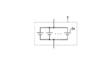
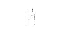
- the battery 2 has a configuration having a cell group in which a plurality of battery cells 2a are connected in parallel as shown in FIG. 2A, or a configuration having a single battery cell 2a as shown in FIG. 2B.
- the battery 2 may include a configuration other than the battery cell.
- FIG. 2C A configuration example of the equalization circuit 3 is shown in FIG. 2C.
- the equalization circuit 3 is a discharge circuit having a resistor 3a and a switch 3b connected in series with each other. The discharge circuit discharges the battery 2 connected in parallel when the switch 3b is in the ON state.
- the state of charge (SOC) of each battery 2 is equalized by adjusting the amount of discharge of each battery 2 by each discharge circuit so that the state of charge of each battery 2 is aligned. can do.
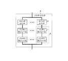
- the battery pack 4 has a configuration in which one or more battery modules 1 connected in series (hereinafter referred to as a battery module string) 5 are connected in parallel. That is, the battery pack 4 is configured to include one or more battery modules 1.
- the battery module 1 is also referred to as a battery module string when the number of battery modules 1 in series is 1, a single battery module 1 is also included in the battery module string 5.
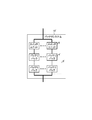
- the battery pack 4 is a structure which has one or more switch units 6 as shown in FIG. Each switch unit 6 corresponds to each battery module string 5. The switch unit 6 has a function of disconnecting the corresponding battery module string 5 from the load 12 and the power source 14 (see FIG. 5 described later).
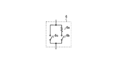
- the switch unit 6 includes a resistor 6a and a switch 6b that are connected in series with each other, and a switch 6c that is connected in parallel to the series circuit including the resistor 6a and the switch 6b. is there.
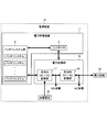
- the power storage device 7 includes a battery system group 8 and a controller 9 that controls the battery system group 8 as shown in FIG.
- the controller 9 corresponds to an example of the “control unit” recited in the claims
- the battery system group 8 includes the “plurality of battery aggregates” recited in the claims, and includes a battery module.
- the string 5 corresponds to an example of a “battery assembly” recited in the claims.
- the battery system group 8 has a configuration in which one or more battery systems 10 are connected in series and / or in parallel.
- FIG. 5 illustrates a battery system group 8 having a configuration in which one or more battery systems 10 are connected in parallel.
- the battery system 10 has a configuration in which one or more battery packs 4 are connected in series and / or in parallel.
- the battery system group 8 is configured to include two or more battery module strings 5.
- the battery system group 8 is connected to the load 12 via the switch 11 and connected to the power source 14 via the switch 13.
- the load 12 consumes electric power from various electronic devices and motors, and the power source 14 supplies electric power from a system power source and a generator to the outside.
- the power storage device 7 according to an embodiment of the present invention discharges when connected to the load 12 and charges when connected to the power source 14. Therefore, charging / discharging of the power storage device 7 according to the embodiment of the present invention can be switched depending on which of the switches 11 and 13 is turned on.
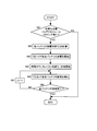
- the power storage device 7 executes the entire operation flow shown in FIG.
- the overall operation flow shown in FIG. 6 is the basic function of the power storage device 7 according to the embodiment of the present invention (voltage / current / temperature measurement and general battery control. Also, step S41 in FIG. Including the acquisition of the maximum capacity change amount in each of the charge / discharge directions in FIG.
- the controller 9 When the controller 9 starts the overall operation flow shown in FIG. 6, it first acquires the current time (step S1). Next, the controller 9 determines whether or not the current time has entered a new time zone t (step S2). Although there is no particular restriction on the setting of each time zone, in this embodiment, the width of each time zone is set to 4 hours as shown in FIG.
- step S2 If the current time is not within the new time zone t (NO in step S2), the process returns to step S1. On the other hand, if the current time is in the new time zone t (YES in step S2), the controller 9 performs all equalization processing if there is a battery module string 5 in the battery system group 8 that is continuing the equalization processing. The operation is forcibly stopped (step S3).
- step S3 the controller 9 executes a statistical process regarding the maximum capacity change amount in the charging direction / discharging direction of the battery system group 8 in the immediately preceding time zone (t-1) (step S4).
- step S4 the controller 9 selects the equalization target battery module string (step S5).
- step S5 the controller 9 controls the switch unit 6 to disconnect the equalization target battery module string from the load 12 and the power source 14 (step S6), and then executes a stabilization process (step S7). Further, equalization processing (step S8) is then performed. After the equalization process is started, the process returns to step S1 without waiting for the end of the equalization process.
- the statistical processing in step S4 is as shown in the operation flow in FIG.
- the controller 9 determines the maximum capacity change amount Qc [t ⁇ 1] in the charging direction of the battery system group 8 in the immediately preceding time zone (t ⁇ 1) and the battery system group 8 in the immediately preceding time zone (t ⁇ 1).
- the maximum capacity change amount Qd [t ⁇ 1] in the discharge direction is acquired (step S41).
- the maximum capacity change amount in the immediately preceding time zone (t ⁇ 1) refers to the maximum value of the change amount of the remaining capacity in the immediately preceding time zone (t ⁇ 1).
- Qini be the remaining capacity of the battery system group 8 at the time of entering the immediately preceding time zone (t ⁇ 1)
- Qnow be the remaining capacity of the battery system group 8 at a certain time in the immediately preceding time zone (t ⁇ 1).
- Qc [t ⁇ 1] and Qd [t ⁇ 1] can be obtained as follows.
- the max function in the following formula means taking the maximum value
- the min function in the following formula means taking the minimum value
- the abs function in the following formula takes an absolute value.
- Qc [t ⁇ 1] max (Qnow ⁇ Qini)
- Qd [t ⁇ 1] abs (min (Qnow ⁇ Qini))
- step S41 the controller 9 determines that the maximum capacity change amount Qc [t ⁇ 1] in the charging direction acquired in step S41 this time is the maximum value Qcmax [t in the maximum capacity change amount in the charging direction acquired in the past. ⁇ 1] is determined (step S42).
- step S42 If Qc [t-1] is not larger than Qcmax [t-1] (NO in step S42), the process proceeds to step S44 without executing the process in step S43. On the other hand, if Qc [t-1] is larger than Qcmax [t-1] (YES in step S42), Qc [t-1] is set as a new Qcmax [t-1] (step S43), and then the process goes to step S44. Transition.
- step S44 the controller 9 determines that the maximum capacity change amount Qd [t ⁇ 1] in the discharge direction acquired in step S41 this time is the maximum value Qdmax [t ⁇ 1] in the past acquired maximum capacity change amount in the discharge direction. ] Is determined.
- step S44 If Qd [t-1] is not larger than Qdmax [t-1] (NO in step S44), the operation flow shown in FIG. 7 is terminated without executing the process of step S45. On the other hand, if Qd [t-1] is larger than Qdmax [t-1] (YES in step S44), Qd [t-1] is set as a new Qdmax [t-1] (step S45), and then FIG. The operation flow shown is finished.
- Qcmax [t ⁇ 1] and Qdmax [t ⁇ 1] are updated according to the operation record of the power storage device 7 according to the embodiment of the present invention by the operation flow shown in FIG.
- the controller 9 calculates the maximum value of the maximum capacity change amount in the charging direction acquired in the past in each time period and the maximum value in the maximum capacity change amount in the discharge direction acquired in the time period of each. I remember it.
- the battery module string selection process for equalization in step S5 is as shown in the operation flow in FIG.
- the controller 9 calculates the SOC maximum value (SOCmax) of the battery 2, the SOC minimum value (SOCmin) of the battery 2, and the SOC deviation ⁇ SOC (SOCmax ⁇ SOCmin). 5 is stored (step S51).
- step S51 the controller 9 calculates a currently allowable charge capacity Ahc and discharge capacity Ahd for each battery module string 5, and stores Ahc and Ahd of each battery module string 5 (step S52).
- the controller 9 After the end of step S52, the controller 9 temporarily selects a battery module string whose ⁇ SOC is greater than the threshold value D (D is a positive constant) as an equalization target battery module string, and sets the battery module string being temporarily selected as ⁇ . (Step S53). It is not necessary to provide an upper limit for ⁇ . Therefore, there is a possibility that the equalization target battery module strings that are temporarily selected are all battery module strings in the battery system group 8. In addition, there is a possibility that the number of equalization target battery module strings temporarily selected is zero.
- step S53 the controller 9 uses the sum ⁇ Ahc of allowable charge capacities of usable battery module strings other than the equalization target battery module string being temporarily selected and uses other than the equalization target battery module string being temporarily selected.
- a sum ⁇ Ahd of allowable discharge capacities of possible battery module strings is calculated (step S54).
- “a battery module string that can be used other than the equalization target battery module string that is temporarily selected” means “all currently selected battery module strings other than the equalization target battery module string that is temporarily selected”. The battery module string that can be connected to the load 12 and the power source 14 without going through the “equalization target battery module string”.
- step S54 the controller 9 obtains a value obtained by multiplying the maximum value Qcmax [t] in the maximum capacity change amount in the charging direction obtained in the past in the time zone t by ⁇ ( ⁇ is a constant of 1 or more). It is determined whether or not ⁇ Ahc is larger (step S55). Note that ⁇ in step S55 corresponds to the case where the maximum capacity change amount in the charging direction in the current time zone t exceeds the maximum value in the maximum capacity change amount in the charging direction acquired in the past in the time zone t. Margin.
- the value obtained by multiplying the maximum value Qcmax [t] by the maximum capacity change amount in the charging direction acquired in the past in the time zone t by ⁇ is the maximum in the charging direction of the battery system group 8 in the current time zone t. This is the predicted maximum value of the capacity change amount.
- step S55 If ⁇ Ahc is not larger than the value obtained by multiplying Qcmax [t] by ⁇ (NO in step S55), if the equalizing target battery module string is determined as the equalizing target battery module string, The power storage device 7 according to an embodiment of the present invention may have insufficient charging capacity in the time zone t. Therefore, if ⁇ Ahc is not larger than the value obtained by multiplying Qcmax [t] by ⁇ (NO in step S55), the equalization target battery module string being temporarily selected is equalized with the smallest ⁇ SOC. Remove from the target battery module string (step S58). As a result, the value of ⁇ is decreased by one (step S58).
- step S55 determines the maximum value in the maximum capacity change amount in the discharge direction obtained in the past in the time zone t. It is determined whether or not ⁇ Ahd is larger than a value obtained by multiplying Qdmax [t] by ⁇ ( ⁇ is a constant equal to or greater than 1) (step S56). Note that ⁇ in step S56 corresponds to a case where the maximum capacity change amount in the discharge direction in the current time zone t exceeds the maximum value in the maximum capacity change amount in the discharge direction obtained in the past in the time zone t. Margin.
- the value obtained by multiplying the maximum value Qdmax [t] in the maximum capacity change amount in the discharge direction obtained in the past in the time zone t by ⁇ is the maximum in the discharge direction of the battery system group 8 in the current time zone t. This is the predicted maximum value of the capacity change amount.
- step S56 If ⁇ Ahd is not larger than the value obtained by multiplying Qdmax [t] by ⁇ (NO in step S56), if the equalization target battery module string is determined as the equalization target battery module string, There exists a possibility that the discharge capability in the time slot
- step S56 determines the equalization target battery module string as the equalization target battery module string. Then, the operation flow shown in FIG.
- step S58 the controller 9 determines whether or not ⁇ is 0 (step S59). If ⁇ is not 0 (NO in step S59), the process returns to step S54. On the other hand, if ⁇ is 0 (YES in step S59), the operation flow shown in FIG. 8 ends with no equalization target battery module string.
- step S6 The stabilization process in step S6 is as shown in the operation flow in FIG.
- the controller 9 initializes the time counter s to 0, and then starts time measurement using the time counter s (step S71).
- step S71 the controller 9 sets ⁇ ( ⁇ is a constant satisfying 0 ⁇ ⁇ 1) as the maximum capacity change amount in the discharge direction after entering the current time zone t in the sum ⁇ Ahd of the allowable discharge capacity. It is determined whether or not the multiplication is exceeded (step S72).
- step S72 If the maximum capacity change amount in the discharge direction after entering the current time zone t does not exceed the sum of the allowable discharge capacity ⁇ Ahd multiplied by ⁇ (NO in step S72), the process immediately proceeds to step S76.
- step S72 if the maximum capacity change amount in the discharge direction after entering the current time zone t exceeds the sum of the allowable discharge capacity ⁇ Ahd multiplied by ⁇ (YES in step S72), the controller 9 is equalized. Among the battery module strings to be normalized, those having the smallest ⁇ SOC stored in step S51 are removed from the equalization targets and reconnected to the load 12 or the power source 14 (step S73). As a result, the value of ⁇ is decreased by one (step S73).
- step S74 the controller 9 determines whether ⁇ is 0 (step S74). If ⁇ is not 0 (NO in step S74), the process proceeds to step S75. On the other hand, if ⁇ is 0 (YES in step S74), the operation flow shown in FIG. 9 ends with no equalization target battery module string.
- step S75 the controller 9 uses the allowable charge capacity Ahc and allowable discharge capacity Ahd stored in step S52 to equalize the sum ⁇ Ahc of the allowable charge capacities of usable battery module strings other than the equalization target battery module string.
- the sum ⁇ Ahd of allowable discharge capacities of usable battery module strings other than the activation target battery module string is recalculated, and then the process proceeds to step S76.
- step S76 the controller 9 determines whether or not the time counter s is equal to or greater than a certain time Trest. If the time counter s is not equal to or longer than the predetermined time Trest (NO in step S76), the process returns to step S72. On the other hand, if the time counter s is equal to or longer than the predetermined time Trest (YES in step S76), the operation flow shown in FIG.
- the fixed time Trest is preferably about 15 to 30 minutes or more.
- step S6 By executing the stabilization process in step S6, the SOC of the battery 2 in the battery module string to be equalized is stabilized, and the equalization accuracy in the equalization process in step S8 is increased.
- step S8 The equalization process in step S8 is as shown in the operation flow in FIG. Note that the controller 9 performs the processes of steps S82 to S85, which will be described later, on each equalization target battery module string in parallel.
- step S81 the controller 9 first determines whether or not there is an equalization target battery module string. If there is no equalization target battery module string (NO in step S81), the operation flow shown in FIG. 10 is immediately terminated. On the other hand, if there is at least one equalization target battery module string (YES in step S81), the process proceeds to step S82.
- step S82 the controller 9 calculates the discharge time T [i] of each battery for aligning the SOC of each battery in the equalization target battery module string.
- the calculation of the discharge time T [i] is, for example, a value (Ah) obtained by multiplying the difference between the target SOC after discharge and the current SOC by the full charge capacity of the battery, and the resistance 3a (see FIG. 2C) and the discharge current (A) obtained from the voltage of the battery 2.
- step S83 discharging is started for the battery having T [i] greater than zero. This discharge is performed using the equalization circuit 3.
- step S84 following step 83 the controller 9 initializes the time counter s to 0 and then starts measuring time by the time counter s.
- step S85 the controller 9 stops discharging the battery whose T [i] is equal to or less than the time counter s.
- step S86 the controller 9 determines whether or not the discharging of all the batteries that started discharging in step S83 is completed. If the discharging of all the batteries that have started discharging in step S83 is not completed (NO in step S86), the time counter s is incremented and the discharging is continued (step S87), and the process returns to step S85. On the other hand, if the discharging of all the batteries that have started discharging in step S83 has ended (YES in step S86), the time counting by the time counter s is ended, and the operation flow shown in FIG. 10 is ended. When the operation flow shown in FIG. 10 is completed, the equalization process has been completed for the batteries in the equalization target battery module string.
- step S8 the equalization target battery module string is always disconnected from the load 12 and the power source 14, and after the equalization process in step S8 is completed, the equalization target battery module string is reconnected to the load 12 or the power supply 14.
- the equalization target battery module string is always disconnected from the load 12 and the power source 14 only during the period until step S83 ends, and after the end of step S83, the equalization target battery module string is connected to the load 12 or You may make it reconnect to the power supply 14.
- step S8 When re-connecting the battery module string disconnected from the load 12 and the power source 14 to the load 12 or the power source 14 after the end of the equalization process in step S8, after the end of step S83, or in step S73 described above First, the switch 6b connected in series to the resistor 6a of the switch unit 6 is turned on, and when the voltage difference between the reconnected battery module string and the battery module string connected in parallel thereto falls within a predetermined range, The switch 6c not connected in series to the resistor 6a is turned on, and then the switch 6b connected in series to the resistor 6a is turned off. As a result, it is possible to prevent the current of the reconnected battery module string from becoming excessive during reconnection.
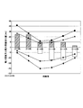
- FIG. 11 shows an example of the power capacity and the maximum capacity change amount in each time zone.
- the hatched bar graph in FIG. 11 indicates a value obtained by multiplying the maximum value Qcmax [t] in the maximum capacity change amount in the past charging direction used in step S55 by ⁇ . Also, the white bar graph in FIG. 11 shows the positive / negative inversion value of the value obtained by multiplying the maximum value Qdmax [t] at the maximum capacity change amount in the discharge direction acquired in the past in step S56 by ⁇ . ing.
- the black square line indicates the total sum of the allowable charge capacities Ahc of all battery module strings.
- the black rhombus polygonal line in FIG. 11 indicates the positive / negative inversion value of the sum of the allowable discharge capacity Ahd of all the battery module strings.
- step S53 represents the total sum of the allowable charge capacities Ahc of usable battery module strings other than the equalization target battery module strings temporarily selected in step S53.
- the black broken line in FIG. 11 indicates the positive / negative inversion value of the sum of the allowable discharge capacities Ahc of battery module strings that can be used other than the equalization target battery module string temporarily selected in step S53.
- the equalization target battery module string temporarily selected in step S53 can be determined as the equalization target battery module string as it is, but in other time zones, The number of equalization target battery module strings is reduced so as to satisfy both the conditions of step S55 and step S56.
- optimization is performed by varying the number of equalization target battery module strings in each time zone, and the power consumption of the load is small and the power supply from the power source is even in the time zone.
- the number of battery module strings to be converted can be increased.
- FIG. 12 shows a schematic configuration example of a power supply device including the power storage device 7 according to an embodiment of the present invention.
- a power supply device 15 shown in FIG. 12 includes a power storage device 7 according to an embodiment of the present invention and a power conversion unit 16.
- the power storage device 7 according to an embodiment of the present invention includes a battery system group 8 and a controller 9.
- the power conversion unit 16 includes a bidirectional DC / DC conversion unit 17 and a bidirectional DC / AC conversion unit 18.
- the controller 9 controls not only the battery system group 8 but also the power conversion unit 16.
- the power supply device 15 shown in FIG. 12 also includes a solar cell 19.
- the bidirectional DC / DC converter 17 converts the DC power output from the battery system group 8 by the discharge of the battery system group 8 into DC power having different voltage values, and both To the DC / AC converter 18.
- the DC power output from the bidirectional DC / DC converter 17 is also used for DC power feeding to a DC electronic device (not shown).
- the bidirectional DC / AC converter 18 converts the DC power output from the bidirectional DC / DC converter 17 into AC power and outputs the AC power to the external power system 20.
- the AC power output from the bidirectional DC / AC converter 18 is also used for AC power feeding to an AC electronic device (not shown).
- a DC electronic device (not shown) and an AC electronic device (not shown) correspond to the load 12 in FIG.
- the bidirectional DC / AC conversion unit 18 converts AC power supplied from the external power system 20 into DC power and outputs the DC power to the bidirectional DC / DC conversion unit 17.
- the bidirectional DC / DC conversion unit 17 converts the DC power supplied from the bidirectional DC / AC conversion unit 18 and / or the DC power output from the solar cell 19 into DC power having different voltage values.
- the solar cell 19 and the power system 20 correspond to the power source 14 in FIG.
- FIG. 13 shows a schematic configuration of an electric vehicle 21 that is an example of a moving body on which the power storage device 7 according to an embodiment of the present invention is mounted (the electric vehicle 21 includes an electric vehicle, HEV (hybrid electric vehicle)). PHEV (Plug-in Hybrid Electric Vehicle) etc. are included).
- HEV hybrid electric vehicle
- PHEV Plug-in Hybrid Electric Vehicle
- An electric vehicle 21 shown in FIG. 13 includes a power storage device 7, a power conversion unit 16, a motor 22, and a generator 23 according to an embodiment of the present invention.
- the power storage device 7 according to an embodiment of the present invention includes a battery system group 8 and a controller 9.
- the power conversion unit 16 includes a bidirectional DC / DC conversion unit 17 and a bidirectional DC / AC conversion unit 18.
- the controller 9 controls not only the battery system group 8 but also the power conversion unit 16.
- the motor 22 is a traveling motor that causes the electric vehicle 21 to travel, and the generator 23 is a generator that generates power using energy when the electric vehicle 21 is regeneratively braked.
- the electric vehicle 21 shown in FIG. 13 also includes a solar cell 19.
- the bidirectional DC / DC converter 17 converts the DC power output from the battery system group 8 by the discharge of the battery system group 8 to DC having different voltage values. It is converted into electric power and output to the bidirectional DC / AC converter 18.
- the bidirectional DC / AC converter 18 converts the DC power output from the bidirectional DC / DC converter 17 into AC power and supplies the AC power to the motor 22.
- the motor 22 corresponds to the load 12 in FIG.
- the motor 22 drives drive wheels (not shown).
- the bidirectional DC / AC conversion unit 18 converts the AC power supplied from the generator 23 into DC power to generate bidirectional DC / AC. Output to the DC converter 17.
- the bidirectional DC / DC conversion unit 17 converts the DC power supplied from the bidirectional DC / AC conversion unit 18 and / or the DC power output from the solar cell 19 into DC power having different voltage values.
- the generator 23 corresponds to the power source 14 in FIG.
- examples of the mobile body equipped with the power storage device according to the present invention include an electric assist bicycle, a ship, an aircraft, a walking robot, and an elevator.
- the motor 22 is an assist motor.
- the motor 22 drives a screw.
- the motor 22 drives the propeller.
- the moving body is a walking robot
- the motor 22 drives the walking foot.
- the motor 22 is a hoisting motor for a lifting rope attached to the bag.
- the use of the power storage device according to the present invention is not limited to the above-described use, but the effect exhibited by the present invention is higher when the application has a high correlation between the time zone and the charge / discharge amount of the power storage device according to the present invention. . Therefore, for example, as in the above-described application, a form used with a solar cell having a high correlation between the time zone and the amount of power generation is preferable.
- the seasonal process is not considered in the statistical process in step S4, but the statistical process may be divided, for example, on a monthly basis.
- the daily unit can also be considered.
- the battery discharge stop timing is controlled by the battery discharge time.
- the battery discharge stop timing is controlled by other general controls. Good.
- the target SOC of the battery is set, the SOC of the battery is calculated at any time during the discharge of the battery, and the time when the target SOC is reached is set as the battery discharge stop timing.
- SOC is used as an indicator of the state of charge of the battery.
- the present invention is not limited to this, and the battery voltage, depth of discharge (DOD), storage amount [Ah], etc. You may use as a parameter
- the battery pack 4 in which the switch unit 6 is provided is used.
- a configuration in which the switch unit is not provided may be used, and the battery system 10 ′ shown in FIG. 14 may be used instead of the battery system 10.
- the battery pack string 5 ′ corresponds to an example of a “battery assembly” recited in the claims.
- the battery system 10 ' has a configuration in which one or more battery packs 4' connected in series (hereinafter referred to as a battery pack string) 5 'are connected in parallel as shown in FIG. That is, the battery system 10 ′ is configured to include one or more battery packs 4 ′. Since the battery pack 4 ′ in series is also referred to as a battery pack string, the single battery pack 4 ′ is also included in the battery pack string 5 ′. Further, the battery system 10 ′ has a configuration having one or more switch units 6 as shown in FIG. 14. Each switch unit 6 corresponds to each battery pack string 5 '. The switch unit 6 has a function of disconnecting the corresponding battery pack string 5 ′ from the load 12 and the power source 14 (see FIG. 5).
- the operation of the power storage device when the battery system 10 ′ shown in FIG. 14 is used instead of the battery system 10 is that the “battery module string” in FIGS. 6 to 10 may be replaced with the “battery pack string”. Detailed description will be omitted.
Landscapes
- Engineering & Computer Science (AREA)
- Power Engineering (AREA)
- Manufacturing & Machinery (AREA)
- Chemical & Material Sciences (AREA)
- Chemical Kinetics & Catalysis (AREA)
- Electrochemistry (AREA)
- General Chemical & Material Sciences (AREA)
- Charge And Discharge Circuits For Batteries Or The Like (AREA)
- Secondary Cells (AREA)
Abstract
負荷及び電源に接続される電力貯蔵装置は、複数のバッテリを含み前記複数のバッテリのうち少なくとも2つは直列に接続されているバッテリ集合体を複数個備え、前記複数個のバッテリ集合体の中から均等化対象バッテリ集合体を選択し、前記均等化対象バッテリ集合体を前記負荷及び前記電源から切り離した後、前記均等化対象バッテリ集合体に対して前記複数のバッテリの充電状態を均等化する均等化処理を開始するコントローラを備える。前記コントローラは、前記複数個のバッテリ集合体の中から選択し得る前記均等化対象バッテリ集合体の最大個数を時間帯に応じて可変する。前記バッテリは、複数のバッテリセルを並列接続したセル群、又は、単一のバッテリセルを有する。
Description
本発明は、電力貯蔵装置並びにそれを備えた電源装置及び移動体に関し、特に、複数のバッテリ間で充電状態を均等化する均等化処理が可能な電力貯蔵装置並びにそれを備えた電源装置及び移動体に関する。
従来より、複数のバッテリ間で充電状態を均等化する均等化処理が可能な電力貯蔵装置が開発されている。
そして、電力貯蔵装置が大電流で充放電を行っている場合でも、均等化処理を高精度に行うために、均等化対象のバッテリモジュール(電池モジュール)を負荷及び電源から切り離す電力貯蔵装置(蓄電システム)が例えば特許文献1に開示されている。
しかしながら、特許文献1に開示されている電力貯蔵装置(蓄電システム)では、同時に均等化処理可能なバッテリモジュール(電池モジュール)の最大個数が固定されているため、均等化処理能力が制限されてしまっていた。
本発明は、上記の状況に鑑み、均等化処理能力が向上し、その結果、使用可能な電力容量が向上する電力貯蔵装置、当該電力貯蔵装置を備える電源装置、及び当該電力貯蔵装置を備える移動体を提供することを目的とする。
上記目的を達成するために本発明に係る電力貯蔵装置は、電力を消費する負荷及び電力を外部に供給する電源に接続される電力貯蔵装置であって、複数のバッテリを含み前記複数のバッテリのうち少なくとも2つは直列に接続されているバッテリ集合体を複数個備え、前記複数個のバッテリ集合体の中から均等化対象バッテリ集合体を選択し、前記均等化対象バッテリ集合体を前記負荷及び前記電源から切り離した後、前記均等化対象バッテリ集合体に対して前記複数のバッテリの充電状態を均等化する均等化処理を開始する制御部を備え、前記制御部は、前記複数個のバッテリ集合体の中から選択し得る前記均等化対象バッテリ集合体の最大個数を時間帯に応じて可変し、前記バッテリは、複数のバッテリセルを並列接続したセル群、又は、単一のバッテリセルを有する構成とする。
上記目的を達成するために本発明に係る電源装置は、上記構成の電力貯蔵装置と、前記電力貯蔵装置に接続される電力変換部とを備える構成とする。
上記目的を達成するために本発明に係る移動体は、上記構成の電力貯蔵装置と、前記電力貯蔵装置から出力される電力により駆動されるモータと、前記電力貯蔵装置と前記モータとの間に接続された電力変換部とを備える構成とする。
本発明によると、複数のバッテリ間で充電状態を均等化する均等化処理の能力が向上し、その結果、使用可能な電力容量が向上する。
本発明の実施形態について図面を参照して以下に説明する。なお、各図において同一の部分には同一の符号を付す。
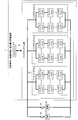
本発明の一実施形態に係る電力貯蔵装置の構成について図1、図2A、図2B、図2C、図3、図4、及び図5を参照して説明する。
<バッテリモジュールの構成>
バッテリモジュール1は、図1に示すように複数のバッテリ2を直列に接続した構成である。また、バッテリモジュール1は、図1に示すようにバッテリ2に並列に接続される均等化回路3を複数備える構成である。
バッテリモジュール1は、図1に示すように複数のバッテリ2を直列に接続した構成である。また、バッテリモジュール1は、図1に示すようにバッテリ2に並列に接続される均等化回路3を複数備える構成である。
バッテリ2は、図2Aに示すように複数のバッテリセル2aが並列接続されたセル群を有する構成、又は、図2Bに示すように単一のバッテリセル2aを有する構成である。なお、バッテリ2はバッテリセル以外の構成を含んでいてもよい。
均等化回路3の一構成例を図2Cに示す。図2Cに示す構成例では、均等化回路3は、互いに直列接続されている抵抗3a及びスイッチ3bを有する放電回路である。当該放電回路は、並列接続されているバッテリ2をスイッチ3bがON状態のときに放電させる。図2Cに示す構成例では、各バッテリ2の充電状態が揃うように各放電回路による各バッテリ2の放電量を調整することで、各バッテリ2の充電状態(state of charge:SOC)を均等化することができる。
<バッテリパックの構成>
バッテリパック4は、図3に示すように1つ以上のバッテリモジュール1を直列に接続したもの(以下、バッテリモジュールストリング)5を1つ以上並列に接続した構成である。すなわち、バッテリパック4は、1つ以上のバッテリモジュール1を有する構成である。なお、バッテリモジュール1の直列数が1である場合もバッテリモジュールストリングと称するので、単一のバッテリモジュール1もバッテリモジュールストリング5に含まれる。また、バッテリパック4は、図3に示すように1以上のスイッチユニット6を有する構成である。各スイッチユニット6は各バッテリモジュールストリング5に対応している。スイッチユニット6は、対応しているバッテリモジュールストリング5を負荷12及び電源14(後述する図5参照)から切り離す機能を有している。
バッテリパック4は、図3に示すように1つ以上のバッテリモジュール1を直列に接続したもの(以下、バッテリモジュールストリング)5を1つ以上並列に接続した構成である。すなわち、バッテリパック4は、1つ以上のバッテリモジュール1を有する構成である。なお、バッテリモジュール1の直列数が1である場合もバッテリモジュールストリングと称するので、単一のバッテリモジュール1もバッテリモジュールストリング5に含まれる。また、バッテリパック4は、図3に示すように1以上のスイッチユニット6を有する構成である。各スイッチユニット6は各バッテリモジュールストリング5に対応している。スイッチユニット6は、対応しているバッテリモジュールストリング5を負荷12及び電源14(後述する図5参照)から切り離す機能を有している。
スイッチユニット6の一構成例を図4に示す。図4に示す構成例では、スイッチユニット6は、互いに直列接続されている抵抗6a及びスイッチ6bと、抵抗6a及びスイッチ6bからなる直列回路に対して並列に接続されるスイッチ6cとを有する構成である。
<本発明の一実施形態に係る電力貯蔵装置の構成>
本発明の一実施形態に係る電力貯蔵装置7は、図5に示すようにバッテリシステム群8と、バッテリシステム群8を制御するコントローラ9とを備えている。本実施形態では、コントローラ9が請求項に記載されている「制御部」の一例に相当し、バッテリシステム群8が請求項に記載されている「複数個のバッテリ集合体」を備え、バッテリモジュールストリング5が請求項に記載されている「バッテリ集合体」の一例に相当する。
本発明の一実施形態に係る電力貯蔵装置7は、図5に示すようにバッテリシステム群8と、バッテリシステム群8を制御するコントローラ9とを備えている。本実施形態では、コントローラ9が請求項に記載されている「制御部」の一例に相当し、バッテリシステム群8が請求項に記載されている「複数個のバッテリ集合体」を備え、バッテリモジュールストリング5が請求項に記載されている「バッテリ集合体」の一例に相当する。
バッテリシステム群8は、1つ以上のバッテリシステム10を直列及び/又は並列に接続した構成である。なお、図5では、1つ以上のバッテリシステム10を並列に接続した構成のバッテリシステム群8を図示している。そして、バッテリシステム10は1つ以上のバッテリパック4を直列及び/又は並列に接続した構成である。ただし、バッテリシステム群8は、2つ以上のバッテリモジュールストリング5を有する構成である。
本実施形態では、図5に示す通り、バッテリシステム群8が、スイッチ11を介して負荷12に接続され尚かつスイッチ13を介して電源14に接続されて使用される。負荷12は、各種電子機器やモータなどの電力を消費するものであり、電源14は、系統電源や発電機などの電力を外部に供給するものである。本発明の一実施形態に係る電力貯蔵装置7は、負荷12と接続されているときに放電し、電源14と接続されているときに充電する。したがって、スイッチ11と13のいずれをオンするかによって、本発明の一実施形態に係る電力貯蔵装置7の充放電を切り替えることができる。
<本発明の一実施形態に係る電力貯蔵装置の動作>
次に、本発明の一実施形態に係る電力貯蔵装置7の動作について図6~図10を参照して説明する。
次に、本発明の一実施形態に係る電力貯蔵装置7の動作について図6~図10を参照して説明する。
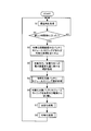
本発明の一実施形態に係る電力貯蔵装置7は図6に示す全体動作フローを実行する。なお、図6に示す全体動作フローは、本発明の一実施形態に係る電力貯蔵装置7の基本機能(電圧・電流・温度の測定や一般的なバッテリ制御。また、後述する図7のステップS41での充放電方向各々への最大容量変化量の取得も含む。)と並行して実行される。
コントローラ9は、図6に示す全体動作フローを開始すると、まず始めに現在時刻を取得する(ステップS1)。次に、コントローラ9は、現在時刻が新しい時間帯tに入ったか否かを判定する(ステップS2)。各時間帯の設定に特に制約は無いが、本実施形態では一例として後述する図11のように各時間帯の幅を4時間にする。
現在時刻が新しい時間帯tに入っていなければ(ステップS2のNO)、ステップS1に戻る。一方、現在時刻が新しい時間帯tに入っていれば(ステップS2のYES)、コントローラ9は、バッテリシステム群8内に均等化処理継続中のバッテリモジュールストリング5があれば、均等化処理を全て強制的に中止する(ステップS3)。
ステップS3の終了後、コントローラ9は、直前の時間帯(t-1)におけるバッテリシステム群8の充電方向/放電方向への最大容量変化量に関する統計処理を実行する(ステップS4)。
ステップS4の終了後、コントローラ9は、均等化対象バッテリモジュールストリングを選択する(ステップS5)。
ステップS5の終了後、コントローラ9は、スイッチユニット6を制御することによって、均等化対象バッテリモジュールストリングを負荷12及び電源14から切り離し(ステップS6)、その後安定化処理(ステップS7)を実行し、さらにその後均等化処理(ステップS8)を実行する。均等化処理の開始後は均等化処理の終了を待たずにステップS1に戻る。
ステップS4の統計処理は、図7に示す動作フローのようになる。コントローラ9は、直前の時間帯(t-1)におけるバッテリシステム群8の充電方向への最大容量変化量Qc[t-1]と、直前の時間帯(t-1)におけるバッテリシステム群8の放電方向への最大容量変化量Qd[t-1]とを取得する(ステップS41)。ここで、直前の時間帯(t-1)における最大容量変化量とは、直前の時間帯(t-1)中の残存容量の変化幅の最大値をいう。直前の時間帯(t-1)に入った時点のバッテリシステム群8の残存容量をQini、直前の時間帯(t-1)中の或る時点のバッテリシステム群8の残存容量をQnowとすると、Qc[t-1]及びQd[t-1]は以下のように求めることができる。なお、下記式中のmax関数は最大値をとることを意味しており、下記式中のmin関数は最小値をとることを意味しており、下記式中のabs関数は絶対値をとることを意味している。
Qc[t-1]=max(Qnow-Qini)
Qd[t-1]=abs(min(Qnow-Qini))
Qc[t-1]=max(Qnow-Qini)
Qd[t-1]=abs(min(Qnow-Qini))
ステップS41の終了後、コントローラ9は、今回ステップS41で取得した充電方向への最大容量変化量Qc[t-1]が、過去取得した充電方向への最大容量変化量での最大値Qcmax[t-1]より大きいか否かを判定する(ステップS42)。
Qc[t-1]がQcmax[t-1]より大きくなければ(ステップS42のNO)、ステップS43の処理を実行せずにステップS44に移行する。一方、Qc[t-1]がQcmax[t-1]より大きければ(ステップS42のYES)、Qc[t-1]を新たなQcmax[t-1]とし(ステップS43)、その後ステップS44に移行する。
ステップS44において、コントローラ9は、今回ステップS41で取得した放電方向への最大容量変化量Qd[t-1]が、過去取得した放電方向への最大容量変化量での最大値Qdmax[t-1]より大きいか否かを判定する。
Qd[t-1]がQdmax[t-1]より大きくなければ(ステップS44のNO)、ステップS45の処理を実行せずに図7に示す動作フローを終了する。一方、Qd[t-1]がQdmax[t-1]より大きければ(ステップS44のYES)、Qd[t-1]を新たなQdmax[t-1]とし(ステップS45)、その後図7に示す動作フローを終了する。
図7に示す動作フローにより、Qcmax[t-1]及びQdmax[t-1]が本発明の一実施形態に係る電力貯蔵装置7の稼働実績に応じて更新される。なお、コントローラ9は、各時間帯それぞれにおける過去取得した充電方向への最大容量変化量での最大値と、各時間帯それぞれにおける過去取得した放電方向への最大容量変化量での最大値とを記憶している。
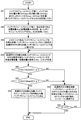
ステップS5の均等化対象バッテリモジュールストリング選択処理は、図8に示す動作フローのようになる。コントローラ9は、バッテリモジュールストリング5毎に、バッテリ2のSOC最大値(SOCmax)と、バッテリ2のSOC最小値(SOCmin)と、SOC偏差ΔSOC(SOCmax-SOCmin)とを計算し、各バッテリモジュールストリング5のΔSOCを記憶する(ステップS51)。
ステップS51の終了後、コントローラ9は、バッテリモジュールストリング5毎に、現在許容できる充電容量Ahcと放電容量Ahdを計算し、各バッテリモジュールストリング5のAhc及びAhdを記憶する(ステップS52)。
ステップS52の終了後、コントローラ9は、ΔSOCが閾値D(Dは正の定数)より大きいバッテリモジュールストリングを、均等化対象バッテリモジュールストリングとして仮選択し、仮選択中のバッテリモジュールストリングをβ個とする(ステップS53)。なお、β個に上限を設ける必要はない。従って、仮選択される均等化対象バッテリモジュールストリングはバッテリシステム群8内の全バッテリモジュールストリングである可能性もある。また、仮選択される均等化対象バッテリモジュールストリングが0個である可能性もある。
ステップS53の終了後、コントローラ9は、仮選択中の均等化対象バッテリモジュールストリング以外の使用可能なバッテリモジュールストリングの許容充電容量の総和ΣAhcと、仮選択中の均等化対象バッテリモジュールストリング以外の使用可能なバッテリモジュールストリングの許容放電容量の総和ΣAhdとを計算する(ステップS54)。ここで、「仮選択中の均等化対象バッテリモジュールストリング以外の使用可能なバッテリモジュールストリング」とは、「仮選択中の均等化対象バッテリモジュールストリング以外の全バッテリモジュールストリング」のうち「仮選択中の均等化対象バッテリモジュールストリング」を経由せずに負荷12及び電源14に接続可能なバッテリモジュールストリングをいう。
ステップS54の終了後、コントローラ9は、時間帯tにおける過去取得した充電方向への最大容量変化量での最大値Qcmax[t]にα(αは1以上の定数)を乗算して得られる値よりΣAhcが大きいか否かを判定する(ステップS55)。なお、ステップS55でのαは、今回の時間帯tにおける充電方向への最大容量変化量が時間帯tにおける過去取得した充電方向への最大容量変化量での最大値を超える場合に対応するためのマージンである。時間帯tにおける過去取得した充電方向への最大容量変化量での最大値Qcmax[t]にαを乗算して得られる値が、今回の時間帯tにおけるバッテリシステム群8の充電方向への最大容量変化量の予測最大値である。
Qcmax[t]にαを乗算して得られる値よりΣAhcが大きくなければ(ステップS55のNO)、仮選択中の均等化対象バッテリモジュールストリングを均等化対象バッテリモジュールストリングに決定してしまうと、本発明の一実施形態に係る電力貯蔵装置7の時間帯tにおける充電能力が不足してしまうおそれがある。このため、Qcmax[t]にαを乗算して得られる値よりΣAhcが大きくなければ(ステップS55のNO)、仮選択中の均等化対象バッテリモジュールストリングの中でΔSOCが最小のものを均等化対象バッテリモジュールストリングから取り除く(ステップS58)。これにより、βの値が1つだけ小さくなる(ステップS58)。
一方、Qcmax[t]にαを乗算して得られる値よりΣAhcが大きければ(ステップS55のYES)、コントローラ9は、時間帯tにおける過去取得した放電方向への最大容量変化量での最大値Qdmax[t]にα(αは1以上の定数)を乗算して得られる値よりΣAhdが大きいか否かを判定する(ステップS56)。なお、ステップS56でのαは、今回の時間帯tにおける放電方向への最大容量変化量が時間帯tにおける過去取得した放電方向への最大容量変化量での最大値を超える場合に対応するためのマージンである。時間帯tにおける過去取得した放電方向への最大容量変化量での最大値Qdmax[t]にαを乗算して得られる値が、今回の時間帯tにおけるバッテリシステム群8の放電方向への最大容量変化量の予測最大値である。
Qdmax[t]にαを乗算して得られる値よりΣAhdが大きくなければ(ステップS56のNO)、仮選択中の均等化対象バッテリモジュールストリングを均等化対象バッテリモジュールストリングに決定してしまうと、本発明の一実施形態に係る電力貯蔵装置7の時間帯tにおける放電能力が不足してしまうおそれがある。このため、Qdmax[t]にαを乗算して得られる値よりΣAhdが大きくなければ(ステップS56のNO)、仮選択中の均等化対象バッテリモジュールストリングの中でΔSOCが最小のものを均等化対象バッテリモジュールストリングから取り除く(ステップS58)。これにより、βの値が1つだけ小さくなる(ステップS58)。
一方、Qdmax[t]にαを乗算して得られる値よりΣAhdが大きければ(ステップS56のYES)、コントローラ9は、仮選択中の均等化対象バッテリモジュールストリングを均等化対象バッテリモジュールストリングと決定し、図8に示す動作フローを終了する。
なお、ステップS58の終了後、コントローラ9は、βが0であるか否かを判定する(ステップS59)。βが0でなければ(ステップS59のNO)、ステップS54に戻る。一方、βが0であれば(ステップS59のYES)、均等化対象バッテリモジュールストリングが無い状態で図8に示す動作フローを終了する。
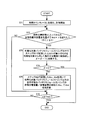
ステップS6の安定化処理は、図9に示す動作フローのようになる。コントローラ9は、時間カウンタsを0に初期化してから、時間カウンタsによる計時を開始する(ステップS71)。
ステップS71の終了後、コントローラ9は、現在の時間帯tに入ってからの放電方向への最大容量変化量が許容放電容量の総和ΣAhdにγ(γは0<γ≦1を満たす定数)を乗算したものを超えたか否かを判定する(ステップS72)。
現在の時間帯tに入ってからの放電方向への最大容量変化量が許容放電容量の総和ΣAhdにγを乗算したものを超えていなければ(ステップS72のNO)、直ちにステップS76に移行する。
一方、現在の時間帯tに入ってからの放電方向への最大容量変化量が許容放電容量の総和ΣAhdにγを乗算したものを超えていれば(ステップS72のYES)、コントローラ9は、均等化対象バッテリモジュールストリングの中でステップS51で記憶したΔSOCが最小のものを均等化対象から外して負荷12又は電源14に再接続する(ステップS73)。これにより、βの値が1つだけ小さくなる(ステップS73)。
ステップS73の終了後、コントローラ9は、βが0であるか否かを判定する(ステップS74)。βが0でなければ(ステップS74のNO)、ステップS75に移行する。一方、βが0であれば(ステップS74のYES)、均等化対象バッテリモジュールストリングが無い状態で図9に示す動作フローを終了する。
ステップS75では、コントローラ9は、ステップS52で記憶した許容充電容量Ahc及び許容放電容量Ahdを用いて、均等化対象バッテリモジュールストリング以外の使用可能なバッテリモジュールストリングの許容充電容量の総和ΣAhcと、均等化対象バッテリモジュールストリング以外の使用可能なバッテリモジュールストリングの許容放電容量の総和ΣAhdとを再計算し、その後ステップS76に移行する。
ステップS76では、コントローラ9は、時間カウンタsが一定時間Trest以上であるか否かを判定する。時間カウンタsが一定時間Trest以上でなければ(ステップS76のNO)、ステップS72に戻る。一方、時間カウンタsが一定時間Trest以上であれば(ステップS76のYES)、図9に示す動作フローを終了する。なお、一定時間Trestは、15分~30分程度以上が望ましい。
ステップS6の安定化処理を実行することにより、均等化対象バッテリモジュールストリング内のバッテリ2のSOCが安定し、ステップS8の均等化処理における均等化の精度が高くなる。
ステップS8の均等化処理は、図10に示す動作フローのようになる。なお、コントローラ9は、各均等化対象バッテリモジュールストリングに対して後述するステップS82~S85の処理を並列に実行する。
コントローラ9は、図10に示す動作フローを開始すると、まず始めに均等化対象バッテリモジュールストリングが有るか否かを判定する(ステップS81)。均等化対象バッテリモジュールストリングがなければ(ステップS81のNO)、直ちに図10に示す動作フローを終了する。一方、均等化対象バッテリモジュールストリングが少なくとも1つ有れば(ステップS81のYES)、ステップS82に移行する。
ステップS82において、コントローラ9は、均等化対象バッテリモジュールストリング内の各バッテリのSOCを揃えるための各バッテリの放電時間T[i]を計算する。放電時間T[i]の計算は、例えば、放電後の目標となるSOCと現在のSOCとの差にバッテリの満充電容量を乗じた値(Ah)と、均等化回路3の抵抗3a(図2C参照)の抵抗値とバッテリ2の電圧から求まる放電電流(A)とを用いて求められる。
ステップS82に続くステップS83において、T[i]が0より大きいバッテリに対して放電を開始する。この放電は、均等化回路3を用いて実行される。
ステップ83に続くステップS84において、コントローラ9は、時間カウンタsを0に初期化させてから、時間カウンタsによる計時を開始する。
ステップS84に続くステップS85において、コントローラ9は、T[i]が時間カウンタs以下になったバッテリの放電を停止させる。
ステップS85に続くステップS86において、コントローラ9は、ステップS83において放電を開始した全バッテリの放電が終了したか否かを判定する。ステップS83において放電を開始した全バッテリの放電が終了していなければ(ステップS86のNO)、時間カウンタsをインクリメントするとともに放電を継続し(ステップS87)、ステップS85に戻る。一方、ステップS83において放電を開始した全バッテリの放電が終了していれば(ステップS86のYES)、時間カウンタsによる計時を終了して、図10に示す動作フローを終了する。図10に示す動作フローが終了した時点で、均等化対象バッテリモジュールストリング内のバッテリについて均等化処理が終了していることになる。
なお、ステップS8の均等化処理中は均等化対象バッテリモジュールストリングを負荷12及び電源14から常時切り離しておきステップS8の均等化処理の終了後に均等化対象バッテリモジュールストリングを負荷12又は電源14に再接続するようにしても良いが、ステップS83が終了する迄の期間のみ均等化対象バッテリモジュールストリングを常時負荷12及び電源14から切り離し、ステップS83の終了後は均等化対象バッテリモジュールストリングを負荷12又は電源14に再接続するようにしても良い。
ステップS8の均等化処理の終了後、ステップS83の終了後、あるいは、上述したステップS73において、負荷12及び電源14から切り離されていたバッテリモジュールストリングを負荷12又は電源14に再接続する際には、まずスイッチユニット6の抵抗6aに直列接続されているスイッチ6bをオンにし、再接続されたバッテリモジュールストリングとそれに並列接続されるバッテリモジュールストリングとの電圧差が所定範囲内になった時点で、抵抗6aに直列接続されていないスイッチ6cをオンにし、その後抵抗6aに直列接続されているスイッチ6bをオフにする。これにより、再接続の際に、再接続されたバッテリモジュールストリングの電流が過大になることを防止することができる。
ここで、図11に各時間帯における電力容量及び最大容量変化量の一例を示す。
図11中の斜線棒グラフは、ステップS55で用いた過去取得した充電方向への最大容量変化量での最大値Qcmax[t]にαを乗算して得られる値を示している。また、図11中の白塗り棒グラフは、ステップS56で用いた過去取得した放電方向への最大容量変化量での最大値Qdmax[t]にαを乗算して得られる値の正負反転値を示している。
図11中の黒塗り四角の折れ線は、全バッテリモジュールストリングの許容充電容量Ahcの総和を示している。また、図11中の黒塗り菱形の折れ線は、全バッテリモジュールストリングの許容放電容量Ahdの総和の正負反転値を示している。
図11中の黒塗り三角の折れ線は、ステップS53で仮選択した均等化対象バッテリモジュールストリング以外の使用可能なバッテリモジュールストリングの許容充電容量Ahcの総和を示している。また、図11中の黒塗り丸の折れ線は、ステップS53で仮選択した均等化対象バッテリモジュールストリング以外の使用可能なバッテリモジュールストリングの許容放電容量Ahcの総和の正負反転値を示している。
図11の例では、22~2時の時間帯では、ステップS53で仮選択した均等化対象バッテリモジュールストリングをそのまま均等化対象バッテリモジュールストリングと決定することができるが、それ以外の時間帯では、ステップS55、ステップS56の両方の条件を満たすように均等化対象バッテリモジュールストリングの個数を減らす。
特許文献1に開示されている電力貯蔵装置のように、同時に均等化処理可能なバッテリモジュールの最大個数が固定される場合、各時間帯において電力貯蔵装置の放電能力や充電能力が不足しないようにするためには、図11の例では10~14時において充電能力に余裕がないため、同時に均等化処理可能なバッテリモジュール(電池モジュール)の最大個数は非常に少なくなってしまう。また、特許文献1の段落0067に記載されているように、平均的な負荷を賄える数に設定すると、図11の例では22~2時や14~18時で均等化処理能力が制限されてしまうことになるとともに、6~10時や10~14時において充電能力が不足し、18~22時において放電能力が不足することになる。
これに対して、本発明では、各時間帯で均等化対象バッテリモジュールストリングの個数を可変して最適化を図り、負荷の消費電力が小さく、且つ、電源からの供給電力が小さい時間帯に均等化対象バッテリモジュールストリングの個数を多くすることができる。これにより、均等化処理能力が向上し、その結果、使用可能な電力容量が向上する。
<本発明の一実施形態に係る電力貯蔵装置の用途例>
本発明の一実施形態に係る電力貯蔵装置7は、例えば電源装置に用いられる。本発明の一実施形態に係る電力貯蔵装置7を備える電源装置の概略構成例を図12に示す。
本発明の一実施形態に係る電力貯蔵装置7は、例えば電源装置に用いられる。本発明の一実施形態に係る電力貯蔵装置7を備える電源装置の概略構成例を図12に示す。
図12に示す電源装置15は、本発明の一実施形態に係る電力貯蔵装置7と、電力変換部16と、を備えている。本発明の一実施形態に係る電力貯蔵装置7は、バッテリシステム群8と、コントローラ9とを備えている。電力変換部16は、双方向DC/DC変換部17と、双方向DC/AC変換部18とを備えている。コントローラ9は、バッテリシステム群8のみならず、電力変換部16も制御する。また、図12に示す電源装置15は、太陽電池19も備えている。
電源装置15の放電動作モードにおいて、双方向DC/DC変換部17は、バッテリシステム群8の放電によりバッテリシステム群8から出力されるDC電力を、異なる電圧値のDC電力に変換して、双方向DC/AC変換部18に出力する。双方向DC/DC変換部17から出力されるDC電力はDC電子機器(不図示)へのDC給電にも用いられる。双方向DC/AC変換部18は、双方向DC/DC変換部17から出力されるDC電力を、AC電力に変換して、外部の電力系統20に出力する。双方向DC/AC変換部18から出力されるAC電力はAC電子機器(不図示)へのAC給電にも用いられる。DC電子機器(不図示)やAC電子機器(不図示)は図5中の負荷12に相当するものである。
電源装置15の充電動作モードにおいて、双方向DC/AC変換部18は、外部の電力系統20から供給されるAC電力を、DC電力に変換して、双方向DC/DC変換部17に出力する。双方向DC/DC変換部17は、双方向DC/AC変換部18から供給されるDC電力及び/又は太陽電池19から出力されるDC電力を、異なる電圧値のDC電力に変換して、バッテリシステム群8に出力し、バッテリシステム群8を充電する。太陽電池19及び電力系統20は図5中の電源14に相当するものである。
また、本発明の一実施形態に係る電力貯蔵装置7は、移動体に搭載されてもよい。本発明の一実施形態に係る電力貯蔵装置7を搭載する移動体の一例である電動車輌21の概略構成を図13に示す(なお、電動車輌21には、電気自動車、HEV(hybrid electric vehicle)、PHEV(Plug-in Hybrid Electric Vehicle)等が含まれる)。
図13に示す電動車輌21は、本発明の一実施形態に係る電力貯蔵装置7と、電力変換部16と、モータ22と、発電機23とを備えている。本発明の一実施形態に係る電力貯蔵装置7は、バッテリシステム群8と、コントローラ9とを備えている。電力変換部16は、双方向DC/DC変換部17と、双方向DC/AC変換部18とを備えている。コントローラ9は、バッテリシステム群8のみならず、電力変換部16も制御する。モータ22は電動車輌21を走行させる走行用モータであり、発電機23は電動車輌21を回生制動する時のエネルギーを利用して発電を行う発電機である。また、図13に示す電動車輌21は、太陽電池19も備えている。
モータ22の駆動により電動車輌21が走行しているときにおいて、双方向DC/DC変換部17は、バッテリシステム群8の放電によりバッテリシステム群8から出力されるDC電力を、異なる電圧値のDC電力に変換して、双方向DC/AC変換部18に出力する。双方向DC/AC変換部18は、双方向DC/DC変換部17から出力されるDC電力を、AC電力に変換して、モータ22に供給する。モータ22は図5中の負荷12に相当するものである。モータ22は駆動輪(不図示)を駆動する。
電動車輌21の回生制動により発電機23が発電しているときにおいて、双方向DC/AC変換部18は、発電機23から供給されるAC電力を、DC電力に変換して、双方向DC/DC変換部17に出力する。双方向DC/DC変換部17は、双方向DC/AC変換部18から供給されるDC電力及び/又は太陽電池19から出力されるDC電力を、異なる電圧値のDC電力に変換して、バッテリシステム群8に出力し、バッテリシステム群8を充電する。発電機23は図5中の電源14に相当するものである。
なお、本発明に係る電力貯蔵装置を搭載する移動体としては、電動車輌の他にも、例えば電動アシスト自転車、船舶、航空機、歩行ロボット、エレベータ等がある。移動体が電動アシスト自転車の場合、モータ22はアシストモータとなる。また、移動体が船舶の場合、モータ22はスクリューを駆動する。また、移動体が航空機の場合、モータ22はプロペラを駆動する。また、移動体が歩行ロボットの場合、モータ22は歩行足を駆動する。また、移動体がエレベータの場合、モータ22は籠に付いた昇降用ロープの巻上げモータとなる。
本発明に係る電力貯蔵装置の用途は、上述した用途に限定されないが、時間帯と本発明に係る電力貯蔵装置の充放電量との相関が高い用途の方が本発明の奏する効果が高くなる。従って、例えば上述した用途のように、時間帯と発電量との相関が高い太陽電池とともに用いる形態が好適である。なお、上述した実施形態では、ステップS4の統計処理において、季節などを考慮していないが、例えば月単位で統計処理を区分けするようにしてもよい。その他に、曜日などによって負荷消費電流が異なることがあるため、日単位も考慮可能である。
<変形例等>
以上、本発明に係る実施形態について説明したが、本発明の範囲はこれに限定されるものではなく、発明の主旨を逸脱しない範囲で種々の変更を加えて実行することができる。
以上、本発明に係る実施形態について説明したが、本発明の範囲はこれに限定されるものではなく、発明の主旨を逸脱しない範囲で種々の変更を加えて実行することができる。
例えば、上述した実施形態では、ステップS8の均等化処理において、バッテリの放電時間によってバッテリの放電停止タイミングが制御されているが、他の一般的な制御によりバッテリの放電停止タイミングが制御されてもよい。他の一般的な制御としては、例えば、バッテリの目標SOCを設定し、バッテリの放電中随時バッテリのSOCを計算し、目標SOCに達した時点をバッテリの放電停止タイミングとする制御がある。
また、例えば、上述した実施形態では、バッテリの充電状態の指標としてSOCを用いているが、これに限らず、バッテリの電圧、放電深度(Depth of discharge:DOD)、蓄電量[Ah]等をバッテリ又はモジュールの充電状態の指標として用いてもよい。
また、例えば、上述した実施形態では、内部にスイッチユニット6が設けられたバッテリパック4を用いたが、バッテリパック4の代わりに、内部にスイッチユニットが設けられていない構成(例えばバッテリパック4からスイッチユニット6を取り除いた構成)のバッテリパック4’を用い、さらに、バッテリシステム10の代わりに、図14に示すバッテリシステム10’を用いるようにしても良い。本変形例では、バッテリパックストリング5’が請求項に記載されている「バッテリ集合体」の一例に相当する。
バッテリシステム10’は、図14に示すように1つ以上のバッテリパック4’を直列に接続したもの(以下、バッテリパックストリング)5’を1つ以上並列に接続した構成である。すなわち、バッテリシステム10’は、1つ以上のバッテリパック4’を有する構成である。なお、バッテリパック4’の直列数が1である場合もバッテリパックストリングと称するので、単一のバッテリパック4’もバッテリパックストリング5’に含まれる。また、バッテリシステム10’は、図14に示すように1以上のスイッチユニット6を有する構成である。各スイッチユニット6は各バッテリパックストリング5’に対応している。スイッチユニット6は、対応しているバッテリパックストリング5’を負荷12及び電源14(図5参照)から切り離す機能を有している。
バッテリシステム10の代わりに、図14に示すバッテリシステム10’を用いた場合の電力貯蔵装置の動作は、図6~図10において「バッテリモジュールストリング」を「バッテリパックストリング」に置換すれば良いので、詳細な説明を省略する。
1 バッテリモジュール
2 バッテリ
2a バッテリセル
3 均等化回路
3a 抵抗
3b スイッチ
4、4’ バッテリパック
5 バッテリモジュールストリング
5’ バッテリパックストリング
6 スイッチユニット
6a 抵抗
6b、6c スイッチ
7 本発明の一実施形態に係る電力貯蔵装置
8 バッテリシステム群
9 コントローラ
10、10’ バッテリシステム
11、13 スイッチ
12 負荷
14 電源
15 電源装置
16 電力変換部
17 双方向DC/DC変換部
18 双方向DC/AC変換部
19 太陽電池
20 電力系統
21 電動車輌
22 モータ
23 発電機
2 バッテリ
2a バッテリセル
3 均等化回路
3a 抵抗
3b スイッチ
4、4’ バッテリパック
5 バッテリモジュールストリング
5’ バッテリパックストリング
6 スイッチユニット
6a 抵抗
6b、6c スイッチ
7 本発明の一実施形態に係る電力貯蔵装置
8 バッテリシステム群
9 コントローラ
10、10’ バッテリシステム
11、13 スイッチ
12 負荷
14 電源
15 電源装置
16 電力変換部
17 双方向DC/DC変換部
18 双方向DC/AC変換部
19 太陽電池
20 電力系統
21 電動車輌
22 モータ
23 発電機
Claims (7)
- 電力を消費する負荷及び電力を外部に供給する電源に接続される電力貯蔵装置であって、
複数のバッテリを含み前記複数のバッテリのうち少なくとも2つは直列に接続されているバッテリ集合体を複数個備え、
前記複数個のバッテリ集合体の中から均等化対象バッテリ集合体を選択し、前記均等化対象バッテリ集合体を前記負荷及び前記電源から切り離した後、前記均等化対象バッテリ集合体に対して前記複数のバッテリの充電状態を均等化する均等化処理を開始する制御部を備え、
前記制御部は、前記複数個のバッテリ集合体の中から選択し得る前記均等化対象バッテリ集合体の最大個数を時間帯に応じて可変し、
前記バッテリは、複数のバッテリセルを並列接続したセル群、又は、単一のバッテリセルを有することを特徴とする電力貯蔵装置。 - 前記制御部は、前記複数のバッテリの充電状態の最大値と最小値との差が所定値以下であるバッテリ集合体を前記均等化対象バッテリ集合体の候補から外して、前記均等化対象バッテリ集合体を選択する請求項1に記載の電力貯蔵装置。
- 各時間帯での前記複数個のバッテリ集合体全体の最大容量変化量の予測値に基づいて、前記複数個のバッテリ集合体の中から選択し得る前記均等化対象バッテリ集合体の最大個数を時間帯に応じて可変する請求項1または請求項2に記載の電力貯蔵装置。
- 前記制御部は、前記均等化対象バッテリ集合体を前記負荷及び前記電源から切り離した後、所定の期間が経過してから、前記均等化処理を開始する請求項1~3のいずれか1項に記載の電力貯蔵装置。
- 前記制御部は、前記所定の期間中に、現在の時間帯に入ってからの前記複数個のバッテリ集合体の最大容量変化量の実績値が所定の閾値を超えた場合に、前記均等化対象バッテリ集合体の少なくとも一つを均等化対象から外す請求項4に記載の電力貯蔵装置。
- 請求項1~5のいずれか1項に記載の電力貯蔵装置と、
前記電力貯蔵装置に接続される電力変換部とを備えることを特徴とする電源装置。 - 請求項1~5のいずれか1項に記載の電力貯蔵装置と、
前記電力貯蔵装置から出力される電力により駆動されるモータと、
前記電力貯蔵装置と前記モータとの間に接続された電力変換部とを備えることを特徴とする移動体。
Applications Claiming Priority (2)
| Application Number | Priority Date | Filing Date | Title |
|---|---|---|---|
| JP2011059117 | 2011-03-17 | ||
| JP2011-059117 | 2011-03-17 |
Publications (1)
| Publication Number | Publication Date |
|---|---|
| WO2012124554A1 true WO2012124554A1 (ja) | 2012-09-20 |
Family
ID=46830627
Family Applications (1)
| Application Number | Title | Priority Date | Filing Date |
|---|---|---|---|
| PCT/JP2012/055741 Ceased WO2012124554A1 (ja) | 2011-03-17 | 2012-03-07 | 電力貯蔵装置並びにそれを備えた電源装置及び移動体 |
Country Status (1)
| Country | Link |
|---|---|
| WO (1) | WO2012124554A1 (ja) |
Cited By (3)
| Publication number | Priority date | Publication date | Assignee | Title |
|---|---|---|---|---|
| CN106542102A (zh) * | 2016-11-26 | 2017-03-29 | 杭州迅蚁网络科技有限公司 | 一种无人机电源管理系统及其控制方法 |
| JP2018125965A (ja) * | 2017-01-31 | 2018-08-09 | 株式会社デンソーテン | 蓄電装置および蓄電制御方法 |
| WO2020244588A1 (zh) * | 2019-06-05 | 2020-12-10 | 深圳市道通智能航空技术有限公司 | 电池管理系统、电池管理方法、电源模块及无人机 |
Citations (4)
| Publication number | Priority date | Publication date | Assignee | Title |
|---|---|---|---|---|
| JP2000324712A (ja) * | 1999-03-09 | 2000-11-24 | Asahi Glass Co Ltd | 電気二重層コンデンサ装置とその電圧制御方法 |
| JP2008160993A (ja) * | 2006-12-25 | 2008-07-10 | Toshiba Corp | エネルギー均等化装置 |
| JP2009081989A (ja) * | 2007-09-25 | 2009-04-16 | O2 Micro Inc | セルバランスのためのシステムおよび方法 |
| JP2010045923A (ja) * | 2008-08-13 | 2010-02-25 | Mitsubishi Heavy Ind Ltd | 蓄電システム |
-
2012
- 2012-03-07 WO PCT/JP2012/055741 patent/WO2012124554A1/ja not_active Ceased
Patent Citations (4)
| Publication number | Priority date | Publication date | Assignee | Title |
|---|---|---|---|---|
| JP2000324712A (ja) * | 1999-03-09 | 2000-11-24 | Asahi Glass Co Ltd | 電気二重層コンデンサ装置とその電圧制御方法 |
| JP2008160993A (ja) * | 2006-12-25 | 2008-07-10 | Toshiba Corp | エネルギー均等化装置 |
| JP2009081989A (ja) * | 2007-09-25 | 2009-04-16 | O2 Micro Inc | セルバランスのためのシステムおよび方法 |
| JP2010045923A (ja) * | 2008-08-13 | 2010-02-25 | Mitsubishi Heavy Ind Ltd | 蓄電システム |
Cited By (3)
| Publication number | Priority date | Publication date | Assignee | Title |
|---|---|---|---|---|
| CN106542102A (zh) * | 2016-11-26 | 2017-03-29 | 杭州迅蚁网络科技有限公司 | 一种无人机电源管理系统及其控制方法 |
| JP2018125965A (ja) * | 2017-01-31 | 2018-08-09 | 株式会社デンソーテン | 蓄電装置および蓄電制御方法 |
| WO2020244588A1 (zh) * | 2019-06-05 | 2020-12-10 | 深圳市道通智能航空技术有限公司 | 电池管理系统、电池管理方法、电源模块及无人机 |
Similar Documents
| Publication | Publication Date | Title |
|---|---|---|
| US11230199B2 (en) | Motor-driven vehicle and control method for motor-driven vehicle | |
| CN105703447B (zh) | 充电电池组的直接平衡充电方法 | |
| KR101677679B1 (ko) | 2차 전지 스택을 위한 전력 관리 회로 | |
| JP6293010B2 (ja) | 蓄電システム | |
| CN102574470B (zh) | 车辆的充电系统及包含该车辆的充电系统的电动车辆 | |
| CN103795104B (zh) | 蓄电系统以及电源系统 | |
| US10559963B2 (en) | Balance correction apparatus and electric storage system | |
| CN104813560B (zh) | 电池组 | |
| JP6777510B2 (ja) | バッテリ制御方法、バッテリ制御装置、及びバッテリパック | |
| US20160156202A1 (en) | Battery pack and method for controlling the same | |
| EP2372865A2 (en) | Power supply device capable of equalizing electrical properties of batteries | |
| EP2367261A2 (en) | Direct-current power source apparatus | |
| WO2012105448A1 (ja) | バッテリモジュール、バッテリシステム、電源装置、及び移動体 | |
| CN102097835A (zh) | 组式电池 | |
| US20120299545A1 (en) | Rechargeable battery power supply starter and cell balancing apparatus | |
| EP3070809B1 (en) | Charge/discharge system | |
| CN105150874B (zh) | 动力电池管理系统及其供电控制方法 | |
| CN105517838A (zh) | 车辆以及电池充电状态监测 | |
| JP2018133851A (ja) | 制御装置、バランス補正装置、蓄電システム、及び、装置 | |
| JP2019041497A (ja) | 電源管理装置 | |
| CN107615561A (zh) | 蓄电装置以及连接控制方法 | |
| CN102934314A (zh) | 电池包 | |
| EP3081425A1 (en) | Vehicle power management device | |
| KR20190071459A (ko) | 배터리 충전 시스템 및 이를 이용한 배터리 모듈의 최대용량 충전 제어방법 | |
| JP2017060313A (ja) | 車両の電源システム |
Legal Events
| Date | Code | Title | Description |
|---|---|---|---|
| 121 | Ep: the epo has been informed by wipo that ep was designated in this application |
Ref document number: 12757829 Country of ref document: EP Kind code of ref document: A1 |
|
| NENP | Non-entry into the national phase |
Ref country code: DE |
|
| 122 | Ep: pct application non-entry in european phase |
Ref document number: 12757829 Country of ref document: EP Kind code of ref document: A1 |
|
| NENP | Non-entry into the national phase |
Ref country code: JP |