WO2012124536A1 - 風力発電装置 - Google Patents
風力発電装置 Download PDFInfo
- Publication number
- WO2012124536A1 WO2012124536A1 PCT/JP2012/055631 JP2012055631W WO2012124536A1 WO 2012124536 A1 WO2012124536 A1 WO 2012124536A1 JP 2012055631 W JP2012055631 W JP 2012055631W WO 2012124536 A1 WO2012124536 A1 WO 2012124536A1
- Authority
- WO
- WIPO (PCT)
- Prior art keywords
- rotor head
- actuator
- rod
- main shaft
- axis
- Prior art date
- Legal status (The legal status is an assumption and is not a legal conclusion. Google has not performed a legal analysis and makes no representation as to the accuracy of the status listed.)
- Ceased
Links
Images






Classifications
-
- F—MECHANICAL ENGINEERING; LIGHTING; HEATING; WEAPONS; BLASTING
- F03—MACHINES OR ENGINES FOR LIQUIDS; WIND, SPRING, OR WEIGHT MOTORS; PRODUCING MECHANICAL POWER OR A REACTIVE PROPULSIVE THRUST, NOT OTHERWISE PROVIDED FOR
- F03D—WIND MOTORS
- F03D7/00—Controlling wind motors
- F03D7/02—Controlling wind motors the wind motors having rotation axis substantially parallel to the air flow entering the rotor
- F03D7/022—Adjusting aerodynamic properties of the blades
- F03D7/0224—Adjusting blade pitch
-
- F—MECHANICAL ENGINEERING; LIGHTING; HEATING; WEAPONS; BLASTING
- F05—INDEXING SCHEMES RELATING TO ENGINES OR PUMPS IN VARIOUS SUBCLASSES OF CLASSES F01-F04
- F05B—INDEXING SCHEME RELATING TO WIND, SPRING, WEIGHT, INERTIA OR LIKE MOTORS, TO MACHINES OR ENGINES FOR LIQUIDS COVERED BY SUBCLASSES F03B, F03D AND F03G
- F05B2260/00—Function
- F05B2260/70—Adjusting of angle of incidence or attack of rotating blades
- F05B2260/74—Adjusting of angle of incidence or attack of rotating blades by turning around an axis perpendicular the rotor centre line
-
- F—MECHANICAL ENGINEERING; LIGHTING; HEATING; WEAPONS; BLASTING
- F05—INDEXING SCHEMES RELATING TO ENGINES OR PUMPS IN VARIOUS SUBCLASSES OF CLASSES F01-F04
- F05B—INDEXING SCHEME RELATING TO WIND, SPRING, WEIGHT, INERTIA OR LIKE MOTORS, TO MACHINES OR ENGINES FOR LIQUIDS COVERED BY SUBCLASSES F03B, F03D AND F03G
- F05B2260/00—Function
- F05B2260/70—Adjusting of angle of incidence or attack of rotating blades
- F05B2260/76—Adjusting of angle of incidence or attack of rotating blades the adjusting mechanism using auxiliary power sources
-
- F—MECHANICAL ENGINEERING; LIGHTING; HEATING; WEAPONS; BLASTING
- F05—INDEXING SCHEMES RELATING TO ENGINES OR PUMPS IN VARIOUS SUBCLASSES OF CLASSES F01-F04
- F05B—INDEXING SCHEME RELATING TO WIND, SPRING, WEIGHT, INERTIA OR LIKE MOTORS, TO MACHINES OR ENGINES FOR LIQUIDS COVERED BY SUBCLASSES F03B, F03D AND F03G
- F05B2260/00—Function
- F05B2260/70—Adjusting of angle of incidence or attack of rotating blades
- F05B2260/79—Bearing, support or actuation arrangements therefor
-
- Y—GENERAL TAGGING OF NEW TECHNOLOGICAL DEVELOPMENTS; GENERAL TAGGING OF CROSS-SECTIONAL TECHNOLOGIES SPANNING OVER SEVERAL SECTIONS OF THE IPC; TECHNICAL SUBJECTS COVERED BY FORMER USPC CROSS-REFERENCE ART COLLECTIONS [XRACs] AND DIGESTS
- Y02—TECHNOLOGIES OR APPLICATIONS FOR MITIGATION OR ADAPTATION AGAINST CLIMATE CHANGE
- Y02E—REDUCTION OF GREENHOUSE GAS [GHG] EMISSIONS, RELATED TO ENERGY GENERATION, TRANSMISSION OR DISTRIBUTION
- Y02E10/00—Energy generation through renewable energy sources
- Y02E10/70—Wind energy
- Y02E10/72—Wind turbines with rotation axis in wind direction
Definitions
- the present invention relates to a wind turbine generator.
- This application claims priority based on Japanese Patent Application No. 2011-054265 filed in Japan on March 11, 2011 and Japanese Patent Application No. 2012-45618 filed in Japan on March 1, 2012. Is hereby incorporated by reference.
- the wind turbine generator includes a tower, a nacelle, a main shaft, a rotor head, a plurality of blades, and a pitch axis rotation mechanism that are erected on the ground.
- the nacelle (rear nacelle) is arranged at the top of the tower.
- the main shaft is disposed in the nacelle and is rotatable.
- the rotor head (front nacelle) is disposed at the tip of the main shaft and protrudes from the nacelle.
- the plurality of blades project radially from the rotor head around the axis of the main shaft.
- the pitch axis rotation mechanism (variable pitch device) rotates the blade around its pitch axis.
- the pitch axis rotation mechanism includes an actuator body (hydraulic cylinder) having an actuator body fixed to the nacelle and a rod that can be expanded and contracted from the actuator body, a link structure that connects the rod and the blade, Is provided.
- the link structure includes a pitch control shaft that is coupled to the rod tip via a rod bearing portion, and a plurality of joints (links and arms) that connect the pitch control shaft and the blade.
- the pitch control shaft passes through the nacelle generator and the main shaft into the rotor head.
- the pitch control shaft can reciprocate in the axial direction of the main shaft as the rod expands and contracts with respect to the actuator body.
- the pitch control shaft can be rotated with respect to the rod by the rod bearing portion.
- the conventional wind power generator has the following problems.
- the number of parts of the link structure for transmitting the rod expansion / contraction of the actuator to the blade is large, and the structure is complicated.
- Such a complicated structure requires time and labor for assembly and maintenance (hereinafter referred to as assembly).
- the generator, main shaft, and rotor head are arranged between the actuator and the blade, the distance from the actuator to the blade becomes longer.
- the total length of the rod and link structure connecting them becomes long. Therefore, the rod and the link structure may be buckled by a large load (thrust) in the axial direction transmitted from the actuator or blade.
- the present invention has been made in view of such circumstances, and an object of the present invention is to provide a wind turbine generator that can improve safety and durability.
- a wind turbine generator includes a nacelle disposed on an upper portion of a tower, a rotatable main shaft disposed on the nacelle, and a rotor head disposed on a tip of the main shaft and protruding from the nacelle.
- the pitch axis rotation mechanism includes an actuator main body supported by the rotor head, an actuator having a rod that can be expanded and contracted from the actuator main body, and a link structure that connects the rod and the blade. It is characterized by extending on the axis of the main shaft.
- the safety and durability of the wind turbine generator can be improved.
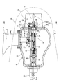
- FIG. 4 is a side cross-sectional view illustrating the internal structure of the rotor head 6.
- FIG. 4 is a front view for explaining the internal structure of the rotor head 6 (as seen from the arrow AA in FIG. 3; a part of the rotor head 6 is shown through).
- FIG. 4 is a front sectional view for explaining the internal structure of the rotor head 6 (taken along the line AA in FIG. 3; a BB sectional view of the rotor head 6).
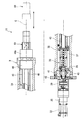
- FIG. 3 is a side sectional view for explaining the structure of an actuator 11.
- FIG. It is the front view which looked at the actuator 11 from the axis C direction. 3 is an enlarged side sectional view showing the vicinity of a tip portion of an actuator body 9.
- the wind turbine generator 1 is a horizontal axis wind turbine generator.
- the wind power generator 1 includes a tower 2, a nacelle 3, and a rotating structure 4.
- the tower 2 is erected on the ground F.
- the nacelle 3 is disposed on the top of the tower 2.
- the rotating structure 4 turns the nacelle 3 around the axis of the tower 2 (about the yaw axis) with respect to the tower 2.
- the wind turbine generator 1 includes a main shaft 5, a rotor head 6, a plurality of blades 7, and a pitch axis rotation mechanism 8.
- the main shaft 5 is disposed so as to be rotatable with respect to the nacelle 3.
- the rotor head 6 is disposed at the tip of the main shaft 5 and protrudes from the nacelle 3.
- the plurality of blades 7 project radially from the rotor head 6 around the axis C of the main shaft 5.
- the pitch axis rotation mechanism 8 is provided in the rotor head 6 and rotates the blade 7 around the pitch axis P.
- the rotor head 6 side (right side in FIG. 2) along the axis C direction of the main shaft 5 is referred to as the distal end side, and the opposite side (left side in FIG. 2) from the rotor head 6 is referred to as the proximal end side.
- a generator (not shown) is disposed on the proximal end side of the main shaft 5. The generator generates electric power by converting mechanical energy obtained by rotating the main shaft 5 around the axis C into electric energy.
- the pitch axis rotation mechanism 8 includes an actuator 11 and a link structure 12 that connects the rod 10 and the blade 7.
- the actuator 11 includes an actuator main body 9 supported by the rotor head 6 and a rod 10 that can extend and contract from the actuator main body 9.
- the proximity switch 13 is a sensor that detects the expansion / contraction position of the rod 10 with respect to the actuator body 9.
- the encoder 14 is a sensor that detects the rotational position of the blade 7 around the pitch axis P.
- the hydraulic brake 15 is a hydraulic brake that restricts the rotation of the blade 7 about the pitch axis P.
- a slip ring 16 In the nacelle 3, a slip ring 16, a hydraulic rotary joint (flexible joint) 17, a hydraulic booster 18, and a small air compressor 19 are disposed.
- the hydraulic booster 18 and the small air compressor 19 may be hydraulic pumps.
- a power cable of a motor 32, a cable of the proximity switch 13, and a cable of the encoder 14 described later are drawn out. These cables pass through the cylindrical main shaft 5 from the base end portion of the rotor head 6 and are connected to a slip ring 16 disposed at the base end portion of the main shaft 5.
- the hydraulic brake 15 passes through the main shaft 5 from the base end portion of the rotor head 6, passes through the cylindrical slip ring 16, and is connected to the hydraulic rotary joint 17.
- a hydraulic booster 18 is connected to the proximal end side of the hydraulic rotary joint 17.
- a small air compressor 19 is connected to the proximal end side of the hydraulic booster 18.
- a driver 20 is installed below the tower 2 on the ground F side.
- a controller 21 is connected to the driver 20.
- the driver 20 is connected to the slip ring 16.
- the controller 21 is connected to the small air compressor 19.
- the driver 20 is not necessarily arranged on the ground. For example, it may be disposed in the nacelle 3.
- the rotor head 6 includes a cylindrical rotor head main body 22 having a hollow inner space, and a disk-shaped rotor head lid 23 disposed at the tip of the rotor head main body 22. And comprising.
- the cross-sectional shape of the rotor head body 22 is substantially triangular (see FIG. 4).
- the blade 7 is supported by the rotor head body 22 so as to be rotatable around the pitch axis P.
- a disk-shaped disk 27 disposed in the rotor head 6 is integrally connected to the blade 7.
- a rod cover 24 is disposed on the surface facing the distal end side of the rotor head lid 23.
- the rod cover 24 covers the rod 10 and the tip side portion of the link structure 12 connected to the rod 10.
- the rod 10 projects from the rotor head lid 23 toward the tip side.
- the rotor head cover 25 is disposed so as to cover the rotor head 6 and the rod cover 24.
- the actuator 11 extends on the axis C of the main shaft 5.
- the proximal end portion of the actuator body 9 (one of the actuator body 9) is fixed to the proximal end portion of the rotor head body 22.
- the tip of the actuator body 9 (the other of the actuator bodies 9) is supported by the rotor head lid 23 via the spherical bearing 26.
- the rod 10 of the actuator 11 is projected from the actuator body 9 toward the tip side.
- the amount of protrusion of the rod 10 toward the tip side can be changed.
- the rod 10 is movable along the axis C direction of the main shaft 5 with respect to the actuator body 9.
- the detailed structure of the actuator 11 will be described later.
- the link structure 12 includes a link angle 28 disposed at the tip of the rod 10 and a link bar 29 that connects the link angle 28 and the disk 27 of the blade 7.
- the link bar 29 includes a link bar main body 31 extending along the direction of the axis C, and link bearings 30 disposed at both ends of the link bar main body 31.
- the link bearing 30 connects the link angle 28 or the disk 27 and the link bar body 31 so as to be relatively rotatable.
- FIG. 6 shows a state where the protruding amount of the rod 10 with respect to the actuator body 9 is the smallest.
- the angle ⁇ 1 formed between the connecting portion of the link rod 29 and the disk 27 (the center of the link bearing 30), the imaginary line L1 passing through the pitch axis P, and the imaginary line LC perpendicular to the axis C is 45 °.
- the imaginary line L2 is an imaginary line that passes through the connecting portion and the pitch axis P in the state where the protruding amount of the rod 10 with respect to the actuator body 9 is the largest.
- An angle ⁇ 2 formed by the virtual line L2 and the virtual line LC is 45 °.
- the pitch axis P extends between the virtual line L1 and the virtual line L2 with the virtual line LC at the center (reference). Can rotate (swing) around.
- Each link bar 29 includes a length adjusting mechanism M.
- a male screw shaft 51 ⁇ / b> L and a male screw shaft 51 ⁇ / b> R are formed at both ends of the link rod main body 31.
- the male screw shaft 51L is a left-hand thread (counterclockwise screw: left-hand thread).
- the male screw shaft 51R is a right-hand thread (right-hand thread).
- a right-handed female thread 52R is formed on the link bearing 30 (30R) connected to the link angle 28.
- the female screw 52L of the link bearing 30L is fitted to the male screw shaft 51L of the link rod body 31.
- the female screw 52R of the link bearing 30R is fitted to the male screw shaft 51R of the link rod main body 31.
- each link bar 29 includes a length adjustment mechanism M.
- the blade 7 is integrally connected to the disk 27.
- the attachment angle of the disk 27 with respect to the blade 7 (rotation angle around the pitch axis P) differs for each blade 7. Therefore, if the lengths S of the three link rods 29 are the same, the pitch angles of the three blades 7 are different (varied). If the pitch angles of the three blades 7 are different, the power generation efficiency of the wind power generator 1 is significantly reduced. Therefore, the length of each link rod 29 is adjusted by the length adjusting mechanism M so that the pitch angles of the three blades 7 coincide with a predetermined angle. For example, in a state where the protruding amount of the rod 10 with respect to the actuator body 9 is the smallest, all the three blades 7 are made to coincide with the pitch angle of 0 °.
- the mounting angle of the disk 27 with respect to the blade 7 is measured in advance for each blade 7 before assembly.
- the length S of each link rod 29 is adjusted using the adjusting mechanism M before assembly. Therefore, when the wind power generator 1 is assembled, the work of adjusting the length of the link rod 29 on the tower 2 becomes unnecessary.
- the wind power generator 1 matches the pitch angle of the three blades 7 by the length adjusting mechanism M, it is possible to prevent a decrease in power generation efficiency.
- the graph showing the relationship between the protrusion amount of the rod 10 and the rotation amount of the disk 27 about the pitch axis P is linear.
- the horizontal axis represents the pitch rotation angle
- the vertical axis represents the actuator stroke.
- the actuator 11 includes an electric drive motor 32, a ball screw 33, a ball spline 34, and a casing 38.
- the ball screw 33 converts the rotational motion energy of the motor 32 into linear motion energy along the axis C direction of the main shaft 5.
- the ball spline 34 is connected to the ball screw 33 and linearly guides the rod 10 in the direction of the axis C of the main shaft 5 with respect to the actuator body 9.
- the casing 38 is formed in a cylindrical shape so as to cover the ball screw 33 and the ball spline 34.
- a reduction gear 35 is disposed at the tip of the motor 32.
- the speed reducer 35 is connected to the screw shaft 36 of the ball screw 33 via a coupling 39.
- the ball screw 33 includes a screw shaft 36 extending along the axis C direction and a cylindrical ball screw nut 37 into which the screw shaft 36 is inserted.
- a rolling element rolling surface (not shown) that is a spiral groove extending in the direction of the axis C while rotating around the axis C is formed on the outer peripheral surface of the screw shaft 36.
- the ball screw nut 37 is formed with an endless infinite circulation path (not shown) including a loaded rolling element rolling surface which is a spiral groove facing the rolling element rolling surface.
- a plurality of balls (rolling elements) are held in the endless circulation path so as to be circulated (not shown).
- the ball screw nut 37 is assembled to the screw shaft 36 through these balls.
- the ball screw nut 37 can reciprocate in the direction of the axis C with respect to the screw shaft 36 by rolling and circulation of the ball.
- the base end portion of the screw shaft 36 is rotatably supported by the angular bearing 40.
- the angular bearing 40 is supported by a housing 41 disposed on the base end side of the casing 38.
- a flange 42 is disposed on the proximal end side of the housing 41.
- the casing 38, the housing 41, and the flange 42 are fixed and integrated with each other.
- the ball spline 34 includes a spline shaft 43 and a spline nut 44.
- the spline shaft 43 is connected to the tip of the ball screw nut 37 and extends along the direction of the axis C.
- the spline shaft 43 is formed in a cylindrical shape, and the screw shaft 36 is inserted therein.
- the spline nut 44 is formed in a cylindrical shape, and the spline shaft 43 is inserted therein.
- the spline nut 44 is fixed to the tip of the casing 38.
- the tip portion 44a of the spline nut 44 protrudes from the casing 38 toward the tip side.
- a plurality of rolling element rolling surfaces 45 which are linear grooves extending along the direction of the axis C, are formed on the outer peripheral surface of the spline shaft 43.
- the spline nut 44 is formed with an endless infinite circuit (not shown) including a loaded rolling element rolling surface which is a linear groove facing the rolling element rolling surface 45.
- a plurality of balls (not shown) are circulated and held in the infinite circulation path.
- the spline nut 44 is assembled to the spline shaft 43 through these balls.
- the spline shaft 43 can reciprocate in the direction of the axis C with respect to the spline nut 44 by rolling and circulation of the ball.
- the spline shaft 43 is the rod 10 that moves in the direction of the axis C with respect to the actuator body 9.
- the actuator body 9 is provided with a cylindrical stand 46 that is connected to the proximal end side of the flange 42 and covers the motor 32.
- the base end portion of the stand 46 is fixed to the base end portion of the rotor head main body 22 with a bolt or the like.
- the base end portion of the actuator body 9 is configured to receive loads in the axial, thrust and bending directions.
- the inside of the stand 46 and the inside of the main shaft 5 communicate with each other.
- the spherical bearing 26 is fitted to the tip end portion 44 a of the spline nut 44 of the actuator body 9.
- the spherical bearing 26 is disposed on the rotor head lid 23 via a spherical bearing flange 47.
- a mounting hole 23 a penetrating in the direction of the axis C is formed in the center of the rotor head lid 23.
- a spherical bearing flange 47 is mounted in the mounting hole 23a.
- the spherical bearing 26 is a support structure for the actuator 11 that is a beam of the rotor head 6 and receives a load in the thrust direction.
- the spherical bearing flange 47 is formed in a cylindrical portion 48 to be inserted into the mounting hole 23a, and a disc-shaped flange portion 49 which is formed at the distal end portion of the cylindrical portion 48 and fixed to the surface facing the distal end side of the rotor head lid 23. And comprising.
- the spherical bearing 26 is inserted into the cylindrical portion 48.
- the spherical bearing 26 is slidable in the direction of the axis C with respect to the cylindrical portion 48.
- the fitting accuracy between the cylindrical portion 48 and the spherical bearing 26 and the fitting accuracy between the spherical bearing 26 and the spline nut 44 are set to a clearance (fitting allowance) that can move relative to each other in the direction of the axis C.
- a through hole 49a penetrating in the direction of the axis C is formed in the center of the flange portion 49. The rod 10 is inserted into the through hole 49a.
- a gap G ⁇ b> 1 is provided between a surface facing the distal end side of the spherical bearing 26 and a surface facing the proximal end side of the flange portion 49. Thereby, the spherical bearing 26 can move in the direction of the axis C of the main shaft 5 with respect to the rotor head 6.
- a gap G2 is provided between the outer peripheral surface of the cylindrical portion 48 and the inner peripheral surface of the mounting hole 23a.
- the pitch axis rotation mechanism 8 that rotates the blade 7 around the pitch axis P is provided in the rotor head 6.
- An actuator 11 of the pitch axis rotation mechanism 8 extends on the axis C of the main shaft 5.
- the rod 10 of the actuator 11 can expand and contract along the axis C direction of the main shaft 5 with respect to the actuator body 9.
- the distance from the actuator 11 to the blade 7 can be shortened (see FIG. 3).
- the overall length of the rod 10 and the link structure 12 of the actuator 11 can be shortened. Therefore, the number of parts of the link structure 12 can be reduced and the configuration can be simplified. Thereby, the wind power generator 1 becomes easy to assemble. Since the total length of the rod 10 and the link structure 12 can be shortened, buckling of the link rod 29 of the rod 10 and the link structure 12 can be prevented by a large load (thrust) in the direction of the axis C transmitted from the actuator 11 and the blade 7. .
- the actuator 11 is disposed in the rotor head 6, a slip ring 16 and a hydraulic rotary joint 17 are installed at the base end portion (rotary structure end) of the main shaft 5 that rotates together with the rotor head 6. Yes (see FIG. 2). Thereby, the motor 32 of the actuator 11 can be disposed in the rotor head 6. Sensors such as a proximity switch 13 and an encoder 14 and a hydraulic brake 15 can be disposed in the rotor head 6. Therefore, the safety and durability of the wind turbine generator 1 are increased.
- the actuator 11 is disposed at the rotation center of the rotor head 6 on the axis C of the main shaft 5. Therefore, the deviation (eccentricity) of the center of gravity of the rotor head 6 is suppressed, and the vibration caused by the eccentricity is suppressed. Occurrence is reduced. Since the rod 10 expansion and contraction of the actuator 11 is performed along the axis C of the main shaft 5, no eccentricity due to the rod 10 expansion and contraction occurs. Therefore, the rotor head 6 rotates stably over a long period. Thus, since the rotation of the rotor head 6 is stabilized, the installation amount of the balancer for balancing the rotation can be reduced.
- the tip end portion of the actuator body 9 is supported by the rotor head 6 via the spherical bearing 26, so that the deviation angle due to misalignment can be canceled.
- the spherical bearing 26 can move in the radial direction perpendicular to the axis C direction of the main shaft 5 with respect to the rotor head 6. Thereby, the eccentricity by misalignment can be canceled.
- the spherical bearing 26 can move in the direction of the axis C of the main shaft 5 with respect to the rotor head 6. Thereby, when the actuator main body 9 etc. expands (contracts) thermally and expands and contracts in the direction of the axis C, the expansion / contraction amount can be absorbed.
- the wind power generator 1 prevents the vibration of the rotor head 6 and the stress on the members such as the spherical bearing 26 from being generated, stable power generation is possible. Since the wind power generator 1 can cancel or absorb the mounting error due to misalignment and the displacement error due to thermal expansion, the processing accuracy of the components may be rough, and the steps such as adjustment work during assembly can be reduced. Thus, productivity is improved and manufacturing costs are reduced.
- the actuator 11 includes a motor 32, a ball screw 33, and a ball spline 34 (see FIG. 3). As a result, the following effects are obtained.
- the actuator 11 can be easily assembled as compared with a conventional actuator such as a hydraulic cylinder.
- the actuator 11 does not leak oil and is easy to maintain.
- the actuator 11 uses an electric drive motor 32 as a drive source, the actuator 11 is excellent in responsiveness. Since the wind power generator 1 is driven by receiving the natural wind W in which the wind direction and the wind speed fluctuate greatly, the actuator 11 of the pitch axis rotation mechanism 8 is required to have high responsiveness.
- the actuator 11 (electrically driven motor 32) can sufficiently meet such requirements.
- the ball screw 33 is used as the speed reduction mechanism of the motor 32, high thrust and low backlash can be realized.
- the external force that the blade 7 of the wind power generator 1 receives from the wind W is very large.
- the actuator 11 of the pitch axis rotation mechanism 8 is required to have high thrust and low backlash.
- the actuator 11 (ball screw 33) can sufficiently meet such requirements.
- the rod 10 is expanded and contracted with respect to the actuator body 9 only by the rolling guide structure of the ball screw 33 and the ball spline 34, so that the accuracy of the expansion and contraction amount of the rod 10 is sufficiently ensured. Therefore, the resistance accompanying the expansion and contraction is small and highly efficient. Thereby, since the capacity
- the connecting portion between the link rod 29 and the disk 27 (the center of the link bearing 30) is located on the virtual line L 1 around the virtual line LC perpendicular to the axis C as the rod 10 extends and contracts. It rotates around the pitch axis P between the lines L2 (see FIG. 6). As a result, the following effects are obtained.
- the graph showing the relationship between the protrusion amount of the rod 10 and the rotation amount of the disk 27 about the pitch axis P is linear, and therefore shows a substantially proportional relationship.
- the portion where the connecting portion is located on the virtual line LC becomes an inflection point so as to connect the concave and convex curves before and after the graph of this portion.
- the efficiency of converting the thrust of the expansion and contraction of the rod 10 along the direction of the axis C into the rotational torque around the pitch axis P is increased, so that the control can be simplified.
- the hydraulic brake 15 that restricts the rotation of the disk 27 of the blade 7 around the pitch axis P is provided, so that the actuator 11 is not operating (the rod 10 is in a stopped state with respect to the actuator body 9). The transmission of external force and vibration in can be prevented.
- the spherical bearing 26 is not limited to the case where the spherical bearing 26 is disposed at the tip portion 44 a of the spline nut 44.
- the spherical bearing 26 may be disposed at the tip of the casing 38.
- one base end portion of the actuator body 9 is fixed to the rotor head 6, and the other tip end portion of the actuator body 9 is supported by the rotor head 6 via the spherical bearing 26.
- a spherical bearing 26 may be disposed at the proximal end portion of the rotor head body 22. In this case, one end of the actuator body 9 is fixed to the rotor head 6. Further, the base end portion which is the other side of the actuator body 9 is supported by the rotor head 6 via the spherical bearing 26.
- the wind power generator 1 is not limited to using balls as rolling elements for the ball screw 33 and the ball spline 34. It may be a rolling element other than a ball such as a cylindrical roller or roller.
- SYMBOLS 1 Wind power generator, 2 ... Tower, 3 ... Nacelle, 5 ... Main shaft, 6 ... Rotor head, 7 ... Blade, 8 ... Pitch axis rotation mechanism, 9 ... Actuator body, 10 ... Rod, 11 ... Actuator, 12 ... Link Structure: 26 ... spherical bearing, 29 ... link rod, 32 ... motor, 33 ... ball screw, 34 ... ball spline, C ... axis of main axis, P ... pitch axis, M ... length adjustment mechanism
Landscapes
- Engineering & Computer Science (AREA)
- Physics & Mathematics (AREA)
- Fluid Mechanics (AREA)
- Life Sciences & Earth Sciences (AREA)
- Sustainable Development (AREA)
- Sustainable Energy (AREA)
- Chemical & Material Sciences (AREA)
- Combustion & Propulsion (AREA)
- Mechanical Engineering (AREA)
- General Engineering & Computer Science (AREA)
- Wind Motors (AREA)
Abstract
Description
本願は、2011年3月11日に日本に出願された特願2011-054265号及び2012年3月1日に日本に出願された特願2012-45618号に基づき優先権を主張し、その内容をここに援用する。
風力発電装置は、地面に立設されたタワー、ナセル、主軸、ロータヘッド、複数のブレード及びピッチ軸回転機構を備える。
ナセル(後部ナセル)は、タワーの上部に配設される。主軸は、ナセルに配設されて回転可能である。ロータヘッド(前部ナセル)は、主軸の先端に配設されてナセルから突出する。複数のブレードは、ロータヘッドから主軸の軸線回りに放射状に突設される。ピッチ軸回転機構(可変ピッチ装置)は、ブレードをそのピッチ軸回りに回転させる。
リンク構造は、ロッド軸受け部を介してロッド先端に連結されるピッチ制御軸と、このピッチ制御軸とブレードとを繋ぐ複数の継ぎ手(リンク及びアーム)と、を含んでいる。
ピッチ制御軸は、ナセルの発電機内及び主軸内を通ってロータヘッド内に至る。ピッチ制御軸は、アクチュエータ本体に対するロッドの伸縮に伴って主軸の軸線方向に往復移動可能である。ピッチ制御軸は、ロッド軸受け部によりロッドに対して回転可能である。
アクチュエータのロッド伸縮をブレードに伝達するためのリンク構造の部品点数が多く、構造が複雑である。このような複雑な構造により、組立やメンテナンス(以下、組立等)に手間がかかる。
図1に示すように、本実施形態に係る風力発電装置1は、水平軸型の風力発電装置である。風力発電装置1は、タワー2、ナセル3及び回転構造4を備える。
タワー2は、地面Fに立設する。ナセル3は、タワー2の上部に配設される。回転構造4は、タワー2に対してナセル3をタワー2の軸回り(ヨー軸回り)に旋回させる。
主軸5は、ナセル3に対して回転可能に配設される。ロータヘッド6は、主軸5の先端に配設されて、ナセル3から突出する。複数のブレード7は、ロータヘッド6から主軸5の軸線C回りに放射状に突設される。ピッチ軸回転機構8は、ロータヘッド6内に設けられて、ブレード7をそのピッチ軸P回りに回転させる。
ナセル3において、主軸5の基端側には、発電機(不図示)が配設される。発電機は、主軸5が軸線C回りに回転することで得られる機械エネルギーを電気エネルギーに変換して電力を発電する。
油圧ブレーキ15は、ロータヘッド6の基端部から主軸5内を通り、筒状のスリップリング16内を通って、油圧ロータリージョイント17に接続される。油圧ロータリージョイント17の基端側には、油圧ブースタ18が接続される。油圧ブースタ18の基端側には、小型空気圧縮機19が接続される。
ドライバ20は、必ずしも地上に配設する必要はない。例えばナセル3内に配設されていてもよい。
ブレード7は、ロータヘッド本体22にピッチ軸P回りに回動可能に支持される。ブレード7には、ロータヘッド6内に配設された円板状のディスク27が一体に連結される。
ロッドカバー24は、ロッド10及びロッド10に連結されるリンク構造12の先端側部分を覆う。ロッド10は、ロータヘッド蓋23から先端側へ向けて突出する。
ロータヘッドカバー25は、ロータヘッド6及びロッドカバー24を覆うように配設される。
アクチュエータ本体9の基端部(アクチュエータ本体9の一方)は、ロータヘッド本体22の基端部に固定される。アクチュエータ本体9の先端部(アクチュエータ本体9の他方)は、球面軸受26を介してロータヘッド蓋23に支持される。
アクチュエータ11の詳しい構造については、後述する。
リンク棒29は、軸線C方向に沿うように延びるリンク棒本体31と、リンク棒本体31の両端部に配設されたリンク軸受30と、を備える。リンク軸受30は、リンクアングル28又はディスク27とリンク棒本体31とを相対回動可能に連結する。
仮想線L2は、アクチュエータ本体9に対するロッド10の突出量が最も大きくなった状態において、連結部分及びピッチ軸Pを通る仮想線である。この仮想線L2と、仮想線LCとのなす角度θ2は、45°である。
図6及び図7に示すように、リンク棒本体31の両端には、雄ねじ軸51Lと雄ねじ軸51Rが形成される。雄ねじ軸51Lは、左ねじ(反時計回りのねじ:left-hand thread)である。雄ねじ軸51Rは、右ねじ(時計回りのねじ:right-hand thread)である。
ディスク27に連結されたリンク軸受30(30L)には、左ねじの雌ねじ52Lが形成される。リンクアングル28に連結されたリンク軸受30(30R)には、右ねじの雌ねじ52Rが形成される。
リンク棒本体31の雄ねじ軸51Lに対して、リンク軸受30Lの雌ねじ52Lが嵌まる。リンク棒本体31の雄ねじ軸51Rに対して、リンク軸受30Rの雌ねじ52Rが嵌まる。
ナット53をリンク軸受30端面から離間させた状態では、リンク棒本体31を軸回転させると、リンク棒29の長さ(リンク長)Sを変更(調整)することができる。
リンク棒29の長さSを調整した後に、各ナット53をリンク軸受30(30R,30L)の端面に押付けることにより、リンク棒29の長さSを固定できる。
このように、各リンク棒29は、それぞれ長さ調整機構Mを備える。
そこで、各リンク棒29の長さを長さ調整機構Mにより調整して、3枚のブレード7のピッチ角を所定の角度に一致させる。例えば、アクチュエータ本体9に対するロッド10の突出量が最も小さくなった状態において、3枚のブレード7を全てピッチ角0°に一致させる。
このように、風力発電装置1は、長さ調整機構Mにより3枚のブレード7のピッチ角を一致させるので、発電効率の低下を防止できる。
ボールねじ33は、モータ32の回転運動のエネルギーを主軸5の軸線C方向に沿う直線運動のエネルギーに変換する。ボールスプライン34は、ボールねじ33に連結されて、アクチュエータ本体9に対して、ロッド10を主軸5の軸線C方向に直線案内する。ケーシング38は、ボールねじ33及びボールスプライン34を覆うように、筒状に形成される。
ねじ軸36の外周面には、軸線C回りに周回しつつ、軸線C方向に延びる螺旋状の溝である転動体転走面(不図示)が形成される。ボールねじナット37には、転動体転走面に対向する螺旋状の溝である負荷転動体転走面を含む無端の無限循環路(不図示)が形成される。無限循環路には、複数のボール(転動体)が循環可能に保持される(不図示)。
スプライン軸43は、ボールねじナット37の先端部に連結されて、軸線C方向に沿って延びる。スプライン軸43は、筒状に形成されて、ねじ軸36が挿入される。スプラインナット44は、筒状に形成されて、スプライン軸43が挿入される。スプラインナット44は、ケーシング38の先端部に固定される。スプラインナット44の先端部分44aは、ケーシング38から先端側へ向けて突出する。
これにより、アクチュエータ本体9の基端部において、アキシャル、スラスト及び曲げ方向の各方向の負荷を受けとめるように構成される。スタンド46の内部と主軸5の内部とは、互いに連通する。
球面軸受26は、球面軸受フランジ47を介して、ロータヘッド蓋23に配設される。ロータヘッド蓋23の中央には、軸線C方向に貫通する取付孔23aが形成される。この取付孔23aに球面軸受フランジ47が装着される。球面軸受26は、ロータヘッド6の梁であるアクチュエータ11の支持構造であり、スラスト方向の荷重を受けとめる。
筒部48内には、球面軸受26が挿入される。球面軸受26は、筒部48に対して軸線C方向に摺動可能である。筒部48と球面軸受26とのはめあい精度及び球面軸受26とスプラインナット44とのはめあい精度は、互いに軸線C方向に相対移動可能なクリアランス(しめ代)に設定される。
フランジ部49の中央には、軸線C方向に貫通する貫通孔49aが形成される。貫通孔49aにはロッド10が挿入される。
組立等が完了した際には、球面軸受フランジ47とロータヘッド蓋23とは、ボルト50によって互いに固定されて、径方向への相対移動が規制される。
このような特別な構成により、下記の顕著な効果を奏する。
これにより、風力発電装置1は、組立等が容易となる。ロッド10及びリンク構造12の全長を短くできるので、アクチュエータ11やブレード7から伝達される軸線C方向への大きな荷重(推力)によって、ロッド10やリンク構造12のリンク棒29の座屈を防止できる。
これにより、ロータヘッド6内に、アクチュエータ11のモータ32を配設できる。ロータヘッド6内に、近接スイッチ13、エンコーダ14等のセンサ及び油圧ブレーキ15を配設できる。
よって、風力発電装置1の安全性や耐久性が高まる。
アクチュエータ11のロッド10伸縮は主軸5の軸線C上に沿って行われるので、ロッド10伸縮による偏心が生じない。
よって、ロータヘッド6は、長期に亘り安定して回転する。このようにロータヘッド6の回転が安定するため、回転バランスをとるためのバランサーの設置量を削減できる。
隙間G1が形成されることにより、球面軸受26がロータヘッド6に対して主軸5の軸線C方向に移動可能である。これにより、アクチュエータ本体9等が熱膨張(収縮)して軸線C方向に伸縮した際に、その伸縮量を吸収できる。
風力発電装置1は、ミスアライメントによる取り付け誤差や熱膨張による変位誤差をキャンセル又は吸収できるため、部品の加工精度が粗くてもよくなり、組立時の調整作業等の工程を削減できる。よって、生産性が向上するとともに製造費用が削減される。
アクチュエータ11は、駆動源として電気駆動のモータ32を用いているので、応答性に優れる。風力発電装置1は、風向きや風速が大きく変動する自然の風Wを受けて駆動するため、ピッチ軸回転機構8のアクチュエータ11には高い応答性が要求される。アクチュエータ11(電気駆動のモータ32)は、このような要求に十分に対応できる。
風力発電装置1のブレード7が風Wから受ける外力は非常に大きい。ブレード7をピッチ軸P回りに回動させために、ピッチ軸回転機構8のアクチュエータ11には、高推力かつ低バックラッシが要求される。アクチュエータ11(ボールねじ33)は、このような要求に十分に対応できる。
これにより、軸線C方向に沿うロッド10伸縮の推力を、ピッチ軸P回りの回転トルクに変換する効率が高くなるので、制御の簡略化ができる。
Claims (5)
- タワーの上部に配設されたナセルと、
前記ナセルに配設された回転可能な主軸と、
前記主軸の先端に配設されて、前記ナセルから突出するロータヘッドと、
前記ロータヘッドから前記主軸の軸線回りに放射状に突設された複数のブレードと、
前記ロータヘッド内に設けられ、前記ブレードをピッチ軸回りに回転させるピッチ軸回転機構と、
を備え、
前記ピッチ軸回転機構は、
前記ロータヘッドに支持されたアクチュエータ本体及び前記アクチュエータ本体から伸縮可能なロッドを有するアクチュエータと、
前記ロッドと前記ブレードとを連結するリンク構造と、を備え、
前記アクチュエータは、前記主軸の軸線上に延設されることを特徴とする風力発電装置。 - 請求項1に記載の風力発電装置であって、
前記アクチュエータ本体の一方が前記ロータヘッドに固定され、
前記アクチュエータ本体の他方が球面軸受を介して前記ロータヘッドに支持されることを特徴とする風力発電装置。 - 請求項2に記載の風力発電装置であって、
前記球面軸受は、前記ロータヘッドに対して、前記主軸の軸線方向に垂直な径方向及び前記軸線方向に移動可能であることを特徴とする風力発電装置。 - 請求項1に記載の風力発電装置であって、
前記アクチュエータは、
モータと、
前記モータの回転運動のエネルギーを前記主軸の軸線方向に沿う直線運動のエネルギーに変換するボールねじと、
前記ボールねじに連結されて、前記アクチュエータ本体に対して前記ロッドを前記主軸の軸線方向に直線案内するボールスプラインと、を含むことを特徴とする風力発電装置。 - 請求項1に記載の風力発電装置であって、
前記リンク構造は、
前記ロッドの先端部と前記ブレードの基端部を連結すると共に、長さ調整機構を有するリンク棒を備えることを特徴とする風力発電装置。
Priority Applications (3)
| Application Number | Priority Date | Filing Date | Title |
|---|---|---|---|
| CN201280012045.XA CN103403347B (zh) | 2011-03-11 | 2012-03-06 | 风力发电装置 |
| US13/985,200 US9410531B2 (en) | 2011-03-11 | 2012-03-06 | Wind turbine generator |
| DE112012001182T DE112012001182T5 (de) | 2011-03-11 | 2012-03-06 | Windturbinengenerator |
Applications Claiming Priority (4)
| Application Number | Priority Date | Filing Date | Title |
|---|---|---|---|
| JP2011-054265 | 2011-03-11 | ||
| JP2011054265 | 2011-03-11 | ||
| JP2012-045618 | 2012-03-01 | ||
| JP2012045618A JP5165804B2 (ja) | 2011-03-11 | 2012-03-01 | 風力発電装置 |
Publications (1)
| Publication Number | Publication Date |
|---|---|
| WO2012124536A1 true WO2012124536A1 (ja) | 2012-09-20 |
Family
ID=46830611
Family Applications (1)
| Application Number | Title | Priority Date | Filing Date |
|---|---|---|---|
| PCT/JP2012/055631 Ceased WO2012124536A1 (ja) | 2011-03-11 | 2012-03-06 | 風力発電装置 |
Country Status (5)
| Country | Link |
|---|---|
| US (1) | US9410531B2 (ja) |
| JP (1) | JP5165804B2 (ja) |
| CN (1) | CN103403347B (ja) |
| DE (1) | DE112012001182T5 (ja) |
| WO (1) | WO2012124536A1 (ja) |
Cited By (1)
| Publication number | Priority date | Publication date | Assignee | Title |
|---|---|---|---|---|
| CN111520599A (zh) * | 2020-04-29 | 2020-08-11 | 中国人民解放军国防科技大学 | 一种轻微型光电吊舱及设备 |
Families Citing this family (5)
| Publication number | Priority date | Publication date | Assignee | Title |
|---|---|---|---|---|
| DE102013012844B3 (de) * | 2013-08-02 | 2014-11-20 | Voith Patent Gmbh | Turbine für ein Strömungskraftwerk |
| JP2015102000A (ja) * | 2013-11-25 | 2015-06-04 | 株式会社明電舎 | 風車ピッチ用ブレーキ機能検出装置 |
| DE102015105249B3 (de) | 2015-04-07 | 2016-09-29 | Technische Universität Berlin | Rotor und Verfahren zum Einstellen eines Blattstellwinkels eines Rotorblatts am Rotor |
| WO2020108714A1 (en) * | 2018-11-27 | 2020-06-04 | Vestas Wind Systems A/S | A wind turbine blade pitch system |
| KR102725063B1 (ko) * | 2024-05-02 | 2024-11-01 | 주식회사 와이이씨 | 풍력발전기의 블레이드 피치 자동조절장치 |
Citations (6)
| Publication number | Priority date | Publication date | Assignee | Title |
|---|---|---|---|---|
| JPH0835482A (ja) * | 1994-07-26 | 1996-02-06 | Mitsubishi Heavy Ind Ltd | 風車の可変ピッチ機構 |
| EP1126163A1 (en) * | 2000-02-16 | 2001-08-22 | Turbowinds N.V./S.A. | Blade pitch angle control device for wind turbine |
| JP2003206846A (ja) * | 2002-01-10 | 2003-07-25 | Mitsubishi Heavy Ind Ltd | 径方向伸縮式風車及びその運転方法 |
| JP2005113823A (ja) * | 2003-10-09 | 2005-04-28 | Yanmar Co Ltd | 風力発電装置 |
| DE102007022511A1 (de) * | 2007-05-14 | 2008-11-20 | Repower Systems Ag | Rotorblattverstellvorrichtung für eine Windenergieanlage |
| EP1998042A1 (de) * | 2007-05-30 | 2008-12-03 | ICEC Holding AG | Rotoreinheit und deren Verwendung |
Family Cites Families (10)
| Publication number | Priority date | Publication date | Assignee | Title |
|---|---|---|---|---|
| US3082826A (en) * | 1958-07-02 | 1963-03-26 | Doman Helicopters Inc | Rotor head with collective pitch control |
| US3736010A (en) * | 1970-12-03 | 1973-05-29 | Lockheed Aircraft Corp | Pitch link assembly and locking device therewith |
| US5042967A (en) * | 1986-09-30 | 1991-08-27 | The Boeing Company | Drive shaft and rotor hub for helicopter flexible rotor system |
| JPH06300106A (ja) * | 1993-04-10 | 1994-10-28 | T H K Kk | 電動アクチュエータ |
| US7071578B1 (en) * | 2002-01-10 | 2006-07-04 | Mitsubishi Heavy Industries, Ltd. | Wind turbine provided with a controller for adjusting active annular plane area and the operating method thereof |
| JP2006046107A (ja) | 2004-08-02 | 2006-02-16 | Yanmar Co Ltd | 風力発電装置 |
| CN101037988A (zh) | 2006-03-16 | 2007-09-19 | 沈阳风电设备发展有限责任公司 | 一种风力发电机变桨距装置 |
| SE533903C2 (sv) * | 2009-01-07 | 2011-03-01 | Morphic Technologies Ab | Vindturbinenhet innefattande en nödbroms med två samverkande gängade delar |
| US8182967B2 (en) | 2009-08-31 | 2012-05-22 | General Electric Company | Optical data storage media and methods for using the same |
| JP5152288B2 (ja) | 2010-08-27 | 2013-02-27 | 株式会社飯塚製作所 | ディフューザの製造方法 |
-
2012
- 2012-03-01 JP JP2012045618A patent/JP5165804B2/ja active Active
- 2012-03-06 CN CN201280012045.XA patent/CN103403347B/zh active Active
- 2012-03-06 DE DE112012001182T patent/DE112012001182T5/de active Pending
- 2012-03-06 WO PCT/JP2012/055631 patent/WO2012124536A1/ja not_active Ceased
- 2012-03-06 US US13/985,200 patent/US9410531B2/en active Active
Patent Citations (6)
| Publication number | Priority date | Publication date | Assignee | Title |
|---|---|---|---|---|
| JPH0835482A (ja) * | 1994-07-26 | 1996-02-06 | Mitsubishi Heavy Ind Ltd | 風車の可変ピッチ機構 |
| EP1126163A1 (en) * | 2000-02-16 | 2001-08-22 | Turbowinds N.V./S.A. | Blade pitch angle control device for wind turbine |
| JP2003206846A (ja) * | 2002-01-10 | 2003-07-25 | Mitsubishi Heavy Ind Ltd | 径方向伸縮式風車及びその運転方法 |
| JP2005113823A (ja) * | 2003-10-09 | 2005-04-28 | Yanmar Co Ltd | 風力発電装置 |
| DE102007022511A1 (de) * | 2007-05-14 | 2008-11-20 | Repower Systems Ag | Rotorblattverstellvorrichtung für eine Windenergieanlage |
| EP1998042A1 (de) * | 2007-05-30 | 2008-12-03 | ICEC Holding AG | Rotoreinheit und deren Verwendung |
Cited By (2)
| Publication number | Priority date | Publication date | Assignee | Title |
|---|---|---|---|---|
| CN111520599A (zh) * | 2020-04-29 | 2020-08-11 | 中国人民解放军国防科技大学 | 一种轻微型光电吊舱及设备 |
| CN111520599B (zh) * | 2020-04-29 | 2022-05-17 | 中国人民解放军国防科技大学 | 一种轻微型光电吊舱及设备 |
Also Published As
| Publication number | Publication date |
|---|---|
| CN103403347B (zh) | 2016-06-08 |
| CN103403347A (zh) | 2013-11-20 |
| US20130323059A1 (en) | 2013-12-05 |
| JP2012207662A (ja) | 2012-10-25 |
| JP5165804B2 (ja) | 2013-03-21 |
| US9410531B2 (en) | 2016-08-09 |
| DE112012001182T5 (de) | 2013-12-12 |
Similar Documents
| Publication | Publication Date | Title |
|---|---|---|
| JP5165804B2 (ja) | 風力発電装置 | |
| RU2523515C2 (ru) | Устройство с подвижным силовым цилиндром для управления ориентацией лопатками вентилятора турбовинтового двигателя | |
| KR102310184B1 (ko) | 헬리콥터 안티-토크 로터 | |
| JP5107353B2 (ja) | ブレードピッチ角制御装置及び風力発電装置 | |
| EP1371845A2 (en) | Wind turbine hub | |
| US20070003411A1 (en) | Variable displacement turbine liner | |
| EP2597304B1 (en) | Wind turbine with a mechanism for synchronously varying the pitch of a multi-blade rotor | |
| CN110228545A (zh) | 一种直线关节及腿足机器人 | |
| US20080218006A1 (en) | Method of assembling a rotor shaft assembly | |
| US12529414B2 (en) | Linear driving mechanism | |
| RU2732083C1 (ru) | Регулировочный блок для регулировки по азимуту и/или для регулировки угла атаки ветроэнергетической установки, соответствующие устройства регулировки с таким регулировочным блоком, ветроэнергетическая установка, способ регулировки роторной лопасти, способ отслеживания направления ветра, а также применение регулировочного блока | |
| CN107208605A (zh) | 手动型叶片节距控制模块 | |
| JP2691136B2 (ja) | 風車の可変ピッチ機構 | |
| CN115473376B (zh) | 一种内外嵌套的并联布局紧凑型光机轴系结构 | |
| CA2114724C (en) | Compensation for kinematic foreshortening effect in pitch control system for rotary wing aircraft | |
| KR101508649B1 (ko) | 풍력발전기용 블레이드 피치 조절장치 및 이를 포함하는 풍력발전기 | |
| US9435378B1 (en) | Roller bearing outer race for hydraulic unit | |
| KR101629354B1 (ko) | 풍력발전기용 블레이드 피치 조절장치 및 이를 포함하는 풍력발전기 | |
| JP2020525709A (ja) | 風力発電装置用回転結合機構、及び風力発電装置用回転結合機構を備えた風力発電装置 | |
| EP2703644B1 (en) | Angular positioning system for a wind turbine | |
| KR101557593B1 (ko) | 풍력 발전 장치 | |
| RU2649723C1 (ru) | Устройство поворота плоского сопла турбореактивного двигателя | |
| JPS6354144B2 (ja) | ||
| WO2014097427A1 (ja) | 再生可能エネルギー型発電装置 | |
| US9528552B2 (en) | Roller bearing outer race for hydraulic unit |
Legal Events
| Date | Code | Title | Description |
|---|---|---|---|
| 121 | Ep: the epo has been informed by wipo that ep was designated in this application |
Ref document number: 12757150 Country of ref document: EP Kind code of ref document: A1 |
|
| WWE | Wipo information: entry into national phase |
Ref document number: 13985200 Country of ref document: US |
|
| WWE | Wipo information: entry into national phase |
Ref document number: 112012001182 Country of ref document: DE Ref document number: 1120120011821 Country of ref document: DE |
|
| 122 | Ep: pct application non-entry in european phase |
Ref document number: 12757150 Country of ref document: EP Kind code of ref document: A1 |