WO2012124379A1 - Hydrocarbon feedstock gasification furnace - Google Patents
Hydrocarbon feedstock gasification furnace Download PDFInfo
- Publication number
- WO2012124379A1 WO2012124379A1 PCT/JP2012/051467 JP2012051467W WO2012124379A1 WO 2012124379 A1 WO2012124379 A1 WO 2012124379A1 JP 2012051467 W JP2012051467 W JP 2012051467W WO 2012124379 A1 WO2012124379 A1 WO 2012124379A1
- Authority
- WO
- WIPO (PCT)
- Prior art keywords
- heat transfer
- gasification furnace
- gasifier
- raw material
- transfer surface
- Prior art date
Links
Images


Classifications
-
- C—CHEMISTRY; METALLURGY
- C10—PETROLEUM, GAS OR COKE INDUSTRIES; TECHNICAL GASES CONTAINING CARBON MONOXIDE; FUELS; LUBRICANTS; PEAT
- C10J—PRODUCTION OF PRODUCER GAS, WATER-GAS, SYNTHESIS GAS FROM SOLID CARBONACEOUS MATERIAL, OR MIXTURES CONTAINING THESE GASES; CARBURETTING AIR OR OTHER GASES
- C10J3/00—Production of combustible gases containing carbon monoxide from solid carbonaceous fuels
- C10J3/72—Other features
- C10J3/723—Controlling or regulating the gasification process
-
- C—CHEMISTRY; METALLURGY
- C10—PETROLEUM, GAS OR COKE INDUSTRIES; TECHNICAL GASES CONTAINING CARBON MONOXIDE; FUELS; LUBRICANTS; PEAT
- C10J—PRODUCTION OF PRODUCER GAS, WATER-GAS, SYNTHESIS GAS FROM SOLID CARBONACEOUS MATERIAL, OR MIXTURES CONTAINING THESE GASES; CARBURETTING AIR OR OTHER GASES
- C10J3/00—Production of combustible gases containing carbon monoxide from solid carbonaceous fuels
- C10J3/46—Gasification of granular or pulverulent flues in suspension
- C10J3/48—Apparatus; Plants
- C10J3/485—Entrained flow gasifiers
-
- C—CHEMISTRY; METALLURGY
- C10—PETROLEUM, GAS OR COKE INDUSTRIES; TECHNICAL GASES CONTAINING CARBON MONOXIDE; FUELS; LUBRICANTS; PEAT
- C10J—PRODUCTION OF PRODUCER GAS, WATER-GAS, SYNTHESIS GAS FROM SOLID CARBONACEOUS MATERIAL, OR MIXTURES CONTAINING THESE GASES; CARBURETTING AIR OR OTHER GASES
- C10J3/00—Production of combustible gases containing carbon monoxide from solid carbonaceous fuels
- C10J3/72—Other features
- C10J3/721—Multistage gasification, e.g. plural parallel or serial gasification stages
-
- C—CHEMISTRY; METALLURGY
- C10—PETROLEUM, GAS OR COKE INDUSTRIES; TECHNICAL GASES CONTAINING CARBON MONOXIDE; FUELS; LUBRICANTS; PEAT
- C10J—PRODUCTION OF PRODUCER GAS, WATER-GAS, SYNTHESIS GAS FROM SOLID CARBONACEOUS MATERIAL, OR MIXTURES CONTAINING THESE GASES; CARBURETTING AIR OR OTHER GASES
- C10J2300/00—Details of gasification processes
- C10J2300/09—Details of the feed, e.g. feeding of spent catalyst, inert gas or halogens
- C10J2300/0913—Carbonaceous raw material
- C10J2300/093—Coal
-
- C—CHEMISTRY; METALLURGY
- C10—PETROLEUM, GAS OR COKE INDUSTRIES; TECHNICAL GASES CONTAINING CARBON MONOXIDE; FUELS; LUBRICANTS; PEAT
- C10J—PRODUCTION OF PRODUCER GAS, WATER-GAS, SYNTHESIS GAS FROM SOLID CARBONACEOUS MATERIAL, OR MIXTURES CONTAINING THESE GASES; CARBURETTING AIR OR OTHER GASES
- C10J2300/00—Details of gasification processes
- C10J2300/09—Details of the feed, e.g. feeding of spent catalyst, inert gas or halogens
- C10J2300/0953—Gasifying agents
- C10J2300/0956—Air or oxygen enriched air
-
- C—CHEMISTRY; METALLURGY
- C10—PETROLEUM, GAS OR COKE INDUSTRIES; TECHNICAL GASES CONTAINING CARBON MONOXIDE; FUELS; LUBRICANTS; PEAT
- C10J—PRODUCTION OF PRODUCER GAS, WATER-GAS, SYNTHESIS GAS FROM SOLID CARBONACEOUS MATERIAL, OR MIXTURES CONTAINING THESE GASES; CARBURETTING AIR OR OTHER GASES
- C10J2300/00—Details of gasification processes
- C10J2300/12—Heating the gasifier
- C10J2300/1246—Heating the gasifier by external or indirect heating
-
- C—CHEMISTRY; METALLURGY
- C10—PETROLEUM, GAS OR COKE INDUSTRIES; TECHNICAL GASES CONTAINING CARBON MONOXIDE; FUELS; LUBRICANTS; PEAT
- C10J—PRODUCTION OF PRODUCER GAS, WATER-GAS, SYNTHESIS GAS FROM SOLID CARBONACEOUS MATERIAL, OR MIXTURES CONTAINING THESE GASES; CARBURETTING AIR OR OTHER GASES
- C10J2300/00—Details of gasification processes
- C10J2300/16—Integration of gasification processes with another plant or parts within the plant
- C10J2300/1603—Integration of gasification processes with another plant or parts within the plant with gas treatment
- C10J2300/1618—Modification of synthesis gas composition, e.g. to meet some criteria
-
- C—CHEMISTRY; METALLURGY
- C10—PETROLEUM, GAS OR COKE INDUSTRIES; TECHNICAL GASES CONTAINING CARBON MONOXIDE; FUELS; LUBRICANTS; PEAT
- C10J—PRODUCTION OF PRODUCER GAS, WATER-GAS, SYNTHESIS GAS FROM SOLID CARBONACEOUS MATERIAL, OR MIXTURES CONTAINING THESE GASES; CARBURETTING AIR OR OTHER GASES
- C10J2300/00—Details of gasification processes
- C10J2300/16—Integration of gasification processes with another plant or parts within the plant
- C10J2300/164—Integration of gasification processes with another plant or parts within the plant with conversion of synthesis gas
- C10J2300/1643—Conversion of synthesis gas to energy
- C10J2300/165—Conversion of synthesis gas to energy integrated with a gas turbine or gas motor
-
- C—CHEMISTRY; METALLURGY
- C10—PETROLEUM, GAS OR COKE INDUSTRIES; TECHNICAL GASES CONTAINING CARBON MONOXIDE; FUELS; LUBRICANTS; PEAT
- C10J—PRODUCTION OF PRODUCER GAS, WATER-GAS, SYNTHESIS GAS FROM SOLID CARBONACEOUS MATERIAL, OR MIXTURES CONTAINING THESE GASES; CARBURETTING AIR OR OTHER GASES
- C10J2300/00—Details of gasification processes
- C10J2300/16—Integration of gasification processes with another plant or parts within the plant
- C10J2300/164—Integration of gasification processes with another plant or parts within the plant with conversion of synthesis gas
- C10J2300/1656—Conversion of synthesis gas to chemicals
- C10J2300/1665—Conversion of synthesis gas to chemicals to alcohols, e.g. methanol or ethanol
-
- C—CHEMISTRY; METALLURGY
- C10—PETROLEUM, GAS OR COKE INDUSTRIES; TECHNICAL GASES CONTAINING CARBON MONOXIDE; FUELS; LUBRICANTS; PEAT
- C10K—PURIFYING OR MODIFYING THE CHEMICAL COMPOSITION OF COMBUSTIBLE GASES CONTAINING CARBON MONOXIDE
- C10K3/00—Modifying the chemical composition of combustible gases containing carbon monoxide to produce an improved fuel, e.g. one of different calorific value, which may be free from carbon monoxide
- C10K3/02—Modifying the chemical composition of combustible gases containing carbon monoxide to produce an improved fuel, e.g. one of different calorific value, which may be free from carbon monoxide by catalytic treatment
- C10K3/04—Modifying the chemical composition of combustible gases containing carbon monoxide to produce an improved fuel, e.g. one of different calorific value, which may be free from carbon monoxide by catalytic treatment reducing the carbon monoxide content, e.g. water-gas shift [WGS]
-
- Y—GENERAL TAGGING OF NEW TECHNOLOGICAL DEVELOPMENTS; GENERAL TAGGING OF CROSS-SECTIONAL TECHNOLOGIES SPANNING OVER SEVERAL SECTIONS OF THE IPC; TECHNICAL SUBJECTS COVERED BY FORMER USPC CROSS-REFERENCE ART COLLECTIONS [XRACs] AND DIGESTS
- Y02—TECHNOLOGIES OR APPLICATIONS FOR MITIGATION OR ADAPTATION AGAINST CLIMATE CHANGE
- Y02E—REDUCTION OF GREENHOUSE GAS [GHG] EMISSIONS, RELATED TO ENERGY GENERATION, TRANSMISSION OR DISTRIBUTION
- Y02E20/00—Combustion technologies with mitigation potential
- Y02E20/16—Combined cycle power plant [CCPP], or combined cycle gas turbine [CCGT]
- Y02E20/18—Integrated gasification combined cycle [IGCC], e.g. combined with carbon capture and storage [CCS]
Definitions
- the present invention relates to a hydrocarbon raw material gasification furnace that gasifies, for example, coal as a hydrocarbon raw material.
- the two-stage, two-chamber entrained bed gasifier proposed as a coal gasifier is the coal, gasifier, and char (non-coal gas in the coal gasification gas) that are put into the first (lower) stage in the gasifier main body.
- Combustor that is operated at high temperature (reacted carbon + ash separated and recovered), and a reductor that gasifies the coal that has been input to the second (upper) stage by the energy of the high-temperature gas from the combustor ( Patent Documents 1 and 2).
- the reaction in the coal gasifier appropriately sets the operating conditions of the gasifier depending on the amount of coal input to the gasifier and the amount and ratio of the gasifying agent (air, oxygen, water vapor, CO 2, etc.). It was set.
- coal gasification gas for example, development of a chemical gasification furnace for obtaining chemical raw materials such as liquid fuel of methanol (CH 3 OH) and gas fuel such as methane (CH 4 ) has been demanded.
- gasifier capable of controlling the composition (H 2 / CO ratio) in the product gas to a desired value is eagerly desired.
- an object of the present invention is to provide a hydrocarbon raw material gasifier capable of controlling the composition in the product gas from the gasifier to a desired value.
- a first invention of the present invention for solving the above-mentioned problems is a heat transfer surface provided in a gasification region of a gasification furnace main body that generates a gasification gas by partially oxidizing a hydrocarbon raw material, and the heat transfer surface.
- a hydrocarbon feedstock gasifier comprising a heat exchanger for exchanging heat of a circulating medium, and a circulation pump for circulating the circulating medium, interposed in a circulation line of a circulating medium circulating in a hot surface is there.
- the heat transfer surface is a panel heat transfer surface, and a plurality of the heat transfer surfaces are provided along the inner surface of the peripheral wall of the gasification furnace main body. It is in.
- a third aspect of the present invention is the hydrocarbon raw material according to the first aspect, wherein the heat transfer surface is a panel-type heat transfer surface and a plurality of the heat transfer surfaces are provided at predetermined intervals in the space of the gasification furnace main body. Located in the gasifier.
- a fourth invention is the carbonization according to the first invention, wherein the heat transfer surface is a panel-type heat transfer surface, and a plurality of the heat transfer surfaces are radially provided in the space of the gasification furnace main body with a predetermined interval. Located in the hydrogen feed gasifier.
- the fifth invention is a hydrocarbon raw material gasification furnace according to any one of the first to fourth inventions, wherein steam is further added in addition to the normal operation conditions of gasification.
- the gasification furnace according to any one of the first to fourth aspects, wherein the gasification furnace includes a combustor provided below the gasification furnace main body and a reductor provided on the upper side of the combustor. It is in a hydrocarbon feedstock gasifier characterized by being a bed gasifier.
- the seventh invention is the hydrocarbon raw material gasifier according to the sixth invention, wherein in addition to normal operation conditions for gasification, steam is introduced into one or both of the reductor and combustor.
- thermometer for measuring the temperature of the product gas at the outlet of the reductor of the gasifier furnace, and the outlet temperature of the product gas to be a predetermined temperature.
- a hydrocarbon raw material gasifier having control means for controlling either or both of the temperature and flow rate of the circulating medium supplied to the heat transfer surface.
- a ninth invention is the gas composition analyzer according to any one of the first to seventh inventions, wherein the gas composition analyzer for measuring the gas composition of the product gas at the outlet of the gasifier furnace and the gas composition of the product gas has a predetermined composition.
- the hydrocarbon raw material gasification furnace has a control means for controlling either or both of the temperature and the flow rate of the circulating medium supplied to the heat transfer surface.
- the heat transfer surface is provided in the gasifier main body reductor, and the fluid temperature and flow rate of the circulating medium supplied to the heat transfer surface are made variable, so that the generated gas in the gasifier main body reductor As a result, the generated gas temperature at the outlet of the gasifier main body reductor can be adjusted.
- the temperature of the product gas By controlling the temperature of the product gas, the composition (H 2 / CO ratio) in the product gas can be controlled, which is required for methanol synthesis and methane (CH 4 ) -rich alternative natural gas (SNG fuel). It becomes possible to supply a gas having a H 2 / CO ratio of 2 or 3, and various chemical raw materials can be provided.
- FIG. 1 is a schematic view of a hydrocarbon raw material gasifier according to a first embodiment.
- FIG. 2 is a diagram showing the relationship between the temperature of the product gas and the composition (H 2 / CO ratio) in the product gas.
- FIG. 3 is a diagram showing an example of equipment using the hydrocarbon raw material gasifier of the present embodiment.
- FIG. 4A is a schematic diagram of a hydrocarbon raw material gasifier according to the second embodiment.
- FIG. 4-2 is a schematic plan view of the gasifier.
- FIG. 4-3 is a schematic plan view of the gasifier.
- FIG. 5 is a schematic view of a hydrocarbon raw material gasifier according to the third embodiment.
- FIG. 6 is a schematic view of a hydrocarbon raw material gasifier according to the fourth embodiment.
- FIG. 1 is a schematic view of a hydrocarbon raw material gasifier according to a first embodiment.
- FIG. 2 is a diagram showing the relationship between the temperature of the product gas and the composition (H 2 / CO ratio) in the
- FIG. 7 is a schematic view of a hydrocarbon raw material gasifier according to the fifth embodiment.
- FIG. 8-1 is a graph showing the relationship between the temperature of the product gas and the composition (H 2 / CO ratio) in the product gas when steam is added (25% addition of steam).
- FIG. 8-2 is a graph showing the relationship between the temperature of the product gas and the composition (H 2 / CO ratio) in the product gas when steam is added (addition of 70% steam).
- FIG. 1 is a schematic view of a hydrocarbon raw material gasifier according to a first embodiment.
- a hydrocarbon raw material gasification furnace (hereinafter referred to as “gasification furnace”) 10 ⁇ / b>
- A is a pressure vessel that generates a product gas 12 by partially oxidizing coal 11 that is a hydrocarbon raw material.
- the heat transfer surface 15 provided in the gasification region of the gasification furnace main body 13 and the circulation line 17 of the circulation medium 16 that circulates in the heat transfer surface 15, and heat that exchanges heat with the circulation medium 16.
- An exchanger 18 and a circulation pump 19 that circulates the circulation medium 16 are provided.
- the gasification furnace 10A is a two-stage entrained bed gasification furnace including a combustor 21 provided below the gasification furnace main body 13 and a reductor 22 provided on the upper side of the combustor 21.
- the coal (pulverized coal) 11 passes through the fuel supply passage 23A, and the gasifying agent (air) 24 passes through the gasifying agent supply passage through a burner (not shown).
- High-temperature combustion gas is generated mainly by partial combustion of the coal 11.
- the recovered char 28 contained in the product gas 12 is separated by a cyclone, a filter, and the like, and is supplied into the combustor 21 through the fuel supply passage 23C.
- the molten slag 25 produced and separated in the high-temperature gas in the combustor adheres to the furnace wall or falls to the furnace bottom, and is discharged downward from the slag tap 26. Further, below the slag tap 26, cooling water 27 for cooling the discharged molten slag 25 is stored at the bottom. Further, coal (pulverized coal) 11 is also introduced into the reductor 22 through a fuel supply passage 23B via a burner (not shown), and mixed with the high-temperature combustion gas generated in the combustor 21 in the reductor 22; A gasification reaction is performed in a high-temperature reducing atmosphere field to obtain a product gas 12.
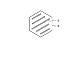
- a plurality of heat transfer surfaces 15 are provided along the wall surface of the reductor 22 of the gasifier main body 13.
- the heat transfer surface 15 is a panel type heat transfer surface along the inner surface of the peripheral wall tube of the gasifier, and a circulation pump 19 that circulates water as the circulation medium 16 on the heat transfer surface 15. And a heat exchanger 18 are interposed in the circulation line 17. Then, the amount of heat absorbed from the product gas 12 in the gasification furnace reductor 22 is controlled by controlling the fluid temperature and the circulation flow rate of the circulation medium 16 supplied to the heat transfer surface 15 with a control device (not shown). .
- a panel type heat transfer surface is used.
- the panel type heat transfer surface is not limited to the panel type as long as the product gas 12 and the circulation medium 16 can exchange heat.
- thermometer (not shown) and the gas composition of the product gas 12 at the outlet of the reductor 22 is measured. Any method of measuring and controlling with a gas composition analyzer may be used.
- reaction gas temperature of the product gas 12 at the outlet of the reductor 22 of the gasification furnace main body 13 is adjusted by controlling the amount of heat absorbed from the product gas 12 in the reductor 22.
- the composition (H 2 / CO ratio) in the product gas 12 can be controlled.
- FIG. 2 is a diagram showing the relationship between the temperature of the product gas and the composition (H 2 / CO ratio) in the product gas.
- the H 2 / CO ratio increases from the time when the reaction temperature decreases to 1,000 ° C.
- H 2 required for methanol synthesis becomes (2CO + 3CO 2).
- the amount of heat absorbed by the product gas 12 in the reductor 22 of the gasification furnace main body 13 is controlled by varying the temperature and flow rate of the fluid supplied to the heat transfer surface 15.
- the product gas temperature at the outlet of the reductor 12 of the gasifier main body 13 is adjusted, and the gas composition (H 2 / CO ratio) in the product gas 12 is adjusted. It can be controlled to achieve a desired ratio.
- FIG. 3 shows an example of equipment using the hydrocarbon raw material gasifier of the present embodiment.
- the purified product gas 12 is supplied to the gas turbine combustor 41, and the gas turbine 42 is driven to generate electricity 44 from the generator 43.
- the obtained methanol and methane can be used not only as fuel but also as starting materials for chemical raw materials. Further, the liquid fuel 34 may be used as an auxiliary fuel for the gasifier or a fuel at the time of startup.
- a two-stage entrained bed gasification furnace comprising a combustor and a reductor provided on the upper side is illustrated, but the present invention is not limited to this, and a one-stage entrained bed gasification furnace. Etc.
- hydrocarbon raw material various carbon raw materials such as coal (bituminous coal, subbituminous coal, brown coal (low-grade coal)), biomass, petroleum coke and the like can be used.
- FIG. 4A is a schematic diagram of a hydrocarbon raw material gasifier according to the second embodiment.
- the hydrocarbon raw material gasifier 10B according to the present embodiment is not provided along the peripheral wall as in the first embodiment, and the heat transfer surface 15 is suspended by a suspension member (not shown). I try to lower it.
- FIGS. 4-2 and 4-3 are schematic plan views of the gasifier.
- a plurality of suspended heat transfer surfaces 15 are arranged in the gasifier main body 13 with a predetermined interval.
- a plurality of suspended heat transfer surfaces 15 are arranged radially in the gasifier main body 13.
- the gasifier cross-sectional temperature can be made more uniform.
- FIG. 5 is a schematic view of a hydrocarbon raw material gasifier according to the third embodiment.
- the hydrocarbon raw material gasification furnace 10C according to the present embodiment is similar to the gasification furnace 10A of the first embodiment, in which steam 50 is further fed into the reductor 22 via a steam supply passage (not shown). Supply.
- the gas composition in the product gas 12 is introduced by introducing steam 50.
- the H 2 / CO ratio can be increased.
- Steam 50 may be charged by introducing steam alone into the reductor 22 or mixing it into a coal nozzle. It should be noted that a single charging and a mixed charging may be combined.
- FIGS. 8A and 8B are diagrams showing the relationship between the temperature of the product gas and the composition (H 2 / CO ratio) in the product gas, depending on the difference in the amount of steam input.
- H 2 / CO ratio 25% of the generated gas
- FIG. 8-2 70% of the generated gas is input as steam.
- FIG. 6 is a schematic view of a hydrocarbon feed gasifier.
- the hydrocarbon raw material gasifier 10D according to the present embodiment is similar to the gasifier 10A according to the first embodiment, in which steam 50 is further supplied into the combustor 21 via a steam supply passage (not shown). Supply.
- steam is introduced into the reductor 22, but in this embodiment, by introducing the steam 50 into the combustor 21, it can be introduced into the gasifier 10D as higher temperature (higher activity) steam. .
- the gas composition H 2 / CO ratio of the product gas 12 can be further increased than in the third embodiment.
- FIG. 7 is a schematic view of a hydrocarbon feed gasifier.
- the hydrocarbon raw material gasification furnace 10E according to the present embodiment combines the third and fourth embodiments, and supplies the steam 50 into the steam supply passage (see FIG. (Not shown).
- the operating range as a gasifier can be widened, and the gas composition H 2 / CO ratio of the product gas 12 can be increased.
- the heat transfer surface 15 is provided in the reductor 22 of the gasification furnace main body 13, and the fluid temperature and flow rate of the circulating medium 16 supplied to the heat transfer surface 15 are variable.
- the amount of heat absorbed from the product gas 12 in the reductor 22 of the gasifier main body 13 can be controlled, and as a result, the temperature of the product gas 12 at the outlet of the reductor 22 of the gasifier main body 13 can be adjusted.
- the composition of the product gas 12 (H 2 / CO ratio) can be controlled by controlling the temperature of the product gas 12, whereby methane (CH 4 ) rich alternative natural gas by methanol synthesis and methanation reaction. It becomes possible to supply gas close to the H 2 / CO ratios 2 and 3 required for (SNG fuel), and various chemical raw materials can be provided.
Abstract
A hydrocarbon feedstock gasification furnace (gasification furnace) (10A) is provided with: a heat transmission surface (15) disposed within the gasification region of a gasification furnace main body (13) configured from a pressure vessel for generating produced gas (12) by partially oxidizing coal (11) which is a hydrocarbon feedstock; a heat exchanger (18) disposed on the path of a circulation line (17) for a circulation medium (16) circulating within the heat transmission surface (15) and for exchanging the heat of the circulation medium (16); and a circulation pump (19) for circulating the circulation medium (16).
Description
本発明は、例えば炭化水素原料として例えば石炭をガス化する炭化水素原料ガス化炉に関する。
The present invention relates to a hydrocarbon raw material gasification furnace that gasifies, for example, coal as a hydrocarbon raw material.
固体の炭化水素原料である石炭を石炭ガス化炉によって石炭ガス化ガスに変換し、ガスタービン複合発電に用いる石炭ガス化複合発電(Integrated coal Gasification Combined Cycle:IGCC)が知られている。
この石炭ガス化複合発電は、埋蔵量が豊富な石炭資源を利用している点、従来の微粉炭火力発電よりも熱効率が高く、二酸化炭素等の大気汚染物質の排出量が少ない点、石炭の灰がガラス質の溶融スラグとして排出され、体積が小さくなる点等の利点を有している。そのため、石炭ガス化複合発電は、今後の石炭火力発電の主力となる技術として開発が進められている。 There is known an integrated coal gasification combined cycle (IGCC) used for gas turbine combined power generation by converting coal, which is a solid hydrocarbon raw material, into coal gasification gas by a coal gasification furnace.
This coal gasification combined power generation uses abundant reserves of coal resources, has higher thermal efficiency than conventional pulverized coal thermal power generation, and emits less air pollutants such as carbon dioxide. The ash is discharged as a glassy molten slag and has advantages such as a reduction in volume. Therefore, coal gasification combined cycle power generation is being developed as a technology that will become the main force of future coal-fired power generation.
石炭ガス化炉として提案される2段2室噴流床ガス化炉は、ガス化炉本体内に1段(下段)目に投入される石炭とガス化剤及びチャー(石炭ガス化ガス中の未反応炭素+灰分を分離回収、リサイクルしたもの)により高温で操業されるコンバスタと、コンバスタからの高温ガスのエネルギにより2段(上段)目に投入された石炭をガス化するリダクタから構成される(特許文献1、2)。
The two-stage, two-chamber entrained bed gasifier proposed as a coal gasifier is the coal, gasifier, and char (non-coal gas in the coal gasification gas) that are put into the first (lower) stage in the gasifier main body. Combustor that is operated at high temperature (reacted carbon + ash separated and recovered), and a reductor that gasifies the coal that has been input to the second (upper) stage by the energy of the high-temperature gas from the combustor ( Patent Documents 1 and 2).
ところで、石炭ガス化炉での反応は、ガス化炉に投入する石炭の量、ガス化剤(空気、酸素、水蒸気、CO2等)の量・割合により、ガス化炉の運転条件を適正に設定していた。
By the way, the reaction in the coal gasifier appropriately sets the operating conditions of the gasifier depending on the amount of coal input to the gasifier and the amount and ratio of the gasifying agent (air, oxygen, water vapor, CO 2, etc.). It was set.
この結果、ガス化炉リダクタの温度は、対象ガス化炉においてガス化炉運転条件を設定したら、同条件で決まり、ガス化炉の出口温度の制御は出来なかった。
As a result, when the gasifier operating conditions were set in the target gasifier, the temperature of the gasifier reductor was determined by the same conditions, and the outlet temperature of the gasifier could not be controlled.
近年、石炭ガス化ガスの適用として、例えばメタノール(CH3OH)の液体燃料、メタン(CH4)等のガス燃料等の化学原料を得る化学用ガス化炉の開発が求められており、そのために、生成ガス中の組成(H2/CO比)を所望の値に制御することが出来るガス化炉の出現が切望されている。
In recent years, as an application of coal gasification gas, for example, development of a chemical gasification furnace for obtaining chemical raw materials such as liquid fuel of methanol (CH 3 OH) and gas fuel such as methane (CH 4 ) has been demanded. In addition, the advent of a gasifier capable of controlling the composition (H 2 / CO ratio) in the product gas to a desired value is eagerly desired.
本発明は、前記問題に鑑み、ガス化炉からの生成ガス中の組成を所望の値に制御することが出来る炭化水素原料ガス化炉を提供することを課題とする。
In view of the above problems, an object of the present invention is to provide a hydrocarbon raw material gasifier capable of controlling the composition in the product gas from the gasifier to a desired value.
上述した課題を解決するための本発明の第1の発明は、炭化水素原料を部分酸化してガス化ガスを生成するガス化炉本体のガス化領域内に設けられる伝熱面と、該伝熱面内を循環する循環媒体の循環ラインに介装され、循環媒体を熱交換する熱交換器と、前記循環媒体を循環する循環ポンプとを有することを特徴とする炭化水素原料ガス化炉にある。
A first invention of the present invention for solving the above-mentioned problems is a heat transfer surface provided in a gasification region of a gasification furnace main body that generates a gasification gas by partially oxidizing a hydrocarbon raw material, and the heat transfer surface. A hydrocarbon feedstock gasifier comprising a heat exchanger for exchanging heat of a circulating medium, and a circulation pump for circulating the circulating medium, interposed in a circulation line of a circulating medium circulating in a hot surface is there.
第2の発明は、第1の発明において、前記伝熱面がパネル型伝熱面であり、ガス化炉本体の周壁内面に沿って複数設けてなることを特徴とする炭化水素原料ガス化炉にある。
According to a second invention, in the first invention, the heat transfer surface is a panel heat transfer surface, and a plurality of the heat transfer surfaces are provided along the inner surface of the peripheral wall of the gasification furnace main body. It is in.
第3の発明は、第1の発明において、前記伝熱面がパネル型伝熱面であり、ガス化炉本体の空間内に所定間隔を持って複数設けてなることを特徴とする炭化水素原料ガス化炉にある。
A third aspect of the present invention is the hydrocarbon raw material according to the first aspect, wherein the heat transfer surface is a panel-type heat transfer surface and a plurality of the heat transfer surfaces are provided at predetermined intervals in the space of the gasification furnace main body. Located in the gasifier.
第4の発明は、第1の発明において、前記伝熱面がパネル型伝熱面であり、ガス化炉本体の空間内に所定間隔を持って放射状に複数設けてなることを特徴とする炭化水素原料ガス化炉にある。
A fourth invention is the carbonization according to the first invention, wherein the heat transfer surface is a panel-type heat transfer surface, and a plurality of the heat transfer surfaces are radially provided in the space of the gasification furnace main body with a predetermined interval. Located in the hydrogen feed gasifier.
第5の発明は、第1乃至4のいずれか一つの発明において、ガス化の通常運転条件に加え、さらに蒸気を投入することを特徴とする炭化水素原料ガス化炉にある。
The fifth invention is a hydrocarbon raw material gasification furnace according to any one of the first to fourth inventions, wherein steam is further added in addition to the normal operation conditions of gasification.
第6の発明は、第1乃至4のいずれか一つの発明において、ガス化炉が、ガス化炉本体内部下方に設けたコンバスタと、該コンバスタの上方側に設けたリダクタとからなる2段噴流床ガス化炉であることを特徴とする炭化水素原料ガス化炉にある。
According to a sixth aspect of the present invention, the gasification furnace according to any one of the first to fourth aspects, wherein the gasification furnace includes a combustor provided below the gasification furnace main body and a reductor provided on the upper side of the combustor. It is in a hydrocarbon feedstock gasifier characterized by being a bed gasifier.
第7の発明は、第6の発明において、ガス化の通常運転条件に加え、リダクタ及びコンバスタのいずれか一方又は両方に蒸気を投入することを特徴とする炭化水素原料ガス化炉にある。
The seventh invention is the hydrocarbon raw material gasifier according to the sixth invention, wherein in addition to normal operation conditions for gasification, steam is introduced into one or both of the reductor and combustor.
第8の発明は、第1乃至7のいずれか一つの発明において、ガス化炉本体のリダクタ出口の生成ガスの温度を計測する温度計と、生成ガスの出口温度を所定の温度となるように、伝熱面に供給する循環媒体の温度、流量のいずれか一方又は両方を制御する制御手段とを有することを特徴とする炭化水素原料ガス化炉にある。
According to an eighth invention, in any one of the first to seventh inventions, a thermometer for measuring the temperature of the product gas at the outlet of the reductor of the gasifier furnace, and the outlet temperature of the product gas to be a predetermined temperature. And a hydrocarbon raw material gasifier having control means for controlling either or both of the temperature and flow rate of the circulating medium supplied to the heat transfer surface.
第9の発明は、第1乃至7のいずれか一つの発明において、ガス化炉本体のリダクタ出口の生成ガスのガス組成を計測するガス組成分析計と、生成ガスのガス組成を所定組成となるように、伝熱面に供給する循環媒体の温度、流量のいずれか一方又は両方を制御する制御手段とを有することを特徴とする炭化水素原料ガス化炉にある。
A ninth invention is the gas composition analyzer according to any one of the first to seventh inventions, wherein the gas composition analyzer for measuring the gas composition of the product gas at the outlet of the gasifier furnace and the gas composition of the product gas has a predetermined composition. Thus, the hydrocarbon raw material gasification furnace has a control means for controlling either or both of the temperature and the flow rate of the circulating medium supplied to the heat transfer surface.
本発明によれば、ガス化炉本体のリダクタに伝熱面を設け、該伝熱面に供給する循環媒体の流体温度・流量を可変とすることにより、ガス化炉本体のリダクタでの生成ガスからの吸熱量を制御し、その結果、ガス化炉本体リダクタ出口での生成ガス温度を調整することが出来る。生成ガスの温度の制御により、生成ガス中の組成(H2/CO比)を制御することができ、これによりメタノール合成、メタン(CH4)リッチな代替天然ガス(SNG燃料)に要求されるH2/CO比2又は3に近いガスを供給することが可能となり、各種化学原料を提供することが出来る。
According to the present invention, the heat transfer surface is provided in the gasifier main body reductor, and the fluid temperature and flow rate of the circulating medium supplied to the heat transfer surface are made variable, so that the generated gas in the gasifier main body reductor As a result, the generated gas temperature at the outlet of the gasifier main body reductor can be adjusted. By controlling the temperature of the product gas, the composition (H 2 / CO ratio) in the product gas can be controlled, which is required for methanol synthesis and methane (CH 4 ) -rich alternative natural gas (SNG fuel). It becomes possible to supply a gas having a H 2 / CO ratio of 2 or 3, and various chemical raw materials can be provided.
以下、この発明につき図面を参照しつつ詳細に説明する。なお、この実施例により本発明が限定されるものではなく、また、実施例が複数ある場合には、各実施例を組み合わせて構成するものも含むものである。また、下記実施例における構成要素には、当業者が容易に想定出来るもの、あるいは実質的に同一のものが含まれる。
Hereinafter, the present invention will be described in detail with reference to the drawings. In addition, this invention is not limited by this Example, Moreover, when there exists multiple Example, what comprises combining each Example is also included. In addition, constituent elements in the following embodiments include those that can be easily assumed by those skilled in the art or those that are substantially the same.
本発明による実施例に係る炭化水素原料ガス化炉について、図面を参照して説明する。図1は、実施例1に係る炭化水素原料ガス化炉の概略図である。
図1に示すように、本実施例に係る炭化水素原料ガス化炉(以下「ガス化炉」という)10Aは、炭化水素原料である石炭11を部分酸化して生成ガス12を生成する圧力容器からなるガス化炉本体13のガス化領域内に設けられる伝熱面15と、該伝熱面15内を循環する循環媒体16の循環ライン17に介装され、循環媒体16を熱交換する熱交換器18と、前記循環媒体16を循環する循環ポンプ19とを有する。 A hydrocarbon raw material gasifier according to an embodiment of the present invention will be described with reference to the drawings. FIG. 1 is a schematic view of a hydrocarbon raw material gasifier according to a first embodiment.
As shown in FIG. 1, a hydrocarbon raw material gasification furnace (hereinafter referred to as “gasification furnace”) 10 </ b> A according to the present embodiment is a pressure vessel that generates aproduct gas 12 by partially oxidizing coal 11 that is a hydrocarbon raw material. The heat transfer surface 15 provided in the gasification region of the gasification furnace main body 13 and the circulation line 17 of the circulation medium 16 that circulates in the heat transfer surface 15, and heat that exchanges heat with the circulation medium 16. An exchanger 18 and a circulation pump 19 that circulates the circulation medium 16 are provided.
図1に示すように、本実施例に係る炭化水素原料ガス化炉(以下「ガス化炉」という)10Aは、炭化水素原料である石炭11を部分酸化して生成ガス12を生成する圧力容器からなるガス化炉本体13のガス化領域内に設けられる伝熱面15と、該伝熱面15内を循環する循環媒体16の循環ライン17に介装され、循環媒体16を熱交換する熱交換器18と、前記循環媒体16を循環する循環ポンプ19とを有する。 A hydrocarbon raw material gasifier according to an embodiment of the present invention will be described with reference to the drawings. FIG. 1 is a schematic view of a hydrocarbon raw material gasifier according to a first embodiment.
As shown in FIG. 1, a hydrocarbon raw material gasification furnace (hereinafter referred to as “gasification furnace”) 10 </ b> A according to the present embodiment is a pressure vessel that generates a
ここで、本実施例に係るガス化炉10Aは、ガス化炉本体13内下方に設けたコンバスタ21と、該コンバスタ21の上方側に設けたリダクタ22とからなる2段噴流床ガス化炉としている。
そして、コンバスタ21内には、燃料供給流路23Aを通って石炭(微粉炭)11が、ガス化剤供給流路を通ってガス化剤(空気)24が図示しないバーナを介して投入され、主に石炭11の部分燃焼により高温燃焼ガスが発生される。なお、生成ガス12中に含まれる回収されたチャー28は、サイクロン、フィルタ等により分離され、燃料供給通路23Cによりコンバスタ21内に供給されている。
また、コンバスタ内高温ガス中で生成分離される溶融スラグ25が炉壁へ付着、又は炉底へ落下し、スラグタップ26から下方へ排出される。
さらに、スラグタップ26の下方には排出された溶融スラグ25を冷却する冷却水27が底部に溜められている。
また、リダクタ22内にも、燃料供給通路23Bを通って石炭(微粉炭)11が図示しないバーナを介して投入され、このリダクタ22内において、コンバスタ21で発生した高温燃焼ガスと混合して、高温の還元雰囲気場においてガス化反応が行われて、生成ガス12を得ている。 Here, thegasification furnace 10A according to the present embodiment is a two-stage entrained bed gasification furnace including a combustor 21 provided below the gasification furnace main body 13 and a reductor 22 provided on the upper side of the combustor 21. Yes.
In thecombustor 21, the coal (pulverized coal) 11 passes through the fuel supply passage 23A, and the gasifying agent (air) 24 passes through the gasifying agent supply passage through a burner (not shown). High-temperature combustion gas is generated mainly by partial combustion of the coal 11. The recovered char 28 contained in the product gas 12 is separated by a cyclone, a filter, and the like, and is supplied into the combustor 21 through the fuel supply passage 23C.
Moreover, themolten slag 25 produced and separated in the high-temperature gas in the combustor adheres to the furnace wall or falls to the furnace bottom, and is discharged downward from the slag tap 26.
Further, below theslag tap 26, cooling water 27 for cooling the discharged molten slag 25 is stored at the bottom.
Further, coal (pulverized coal) 11 is also introduced into thereductor 22 through a fuel supply passage 23B via a burner (not shown), and mixed with the high-temperature combustion gas generated in the combustor 21 in the reductor 22; A gasification reaction is performed in a high-temperature reducing atmosphere field to obtain a product gas 12.
そして、コンバスタ21内には、燃料供給流路23Aを通って石炭(微粉炭)11が、ガス化剤供給流路を通ってガス化剤(空気)24が図示しないバーナを介して投入され、主に石炭11の部分燃焼により高温燃焼ガスが発生される。なお、生成ガス12中に含まれる回収されたチャー28は、サイクロン、フィルタ等により分離され、燃料供給通路23Cによりコンバスタ21内に供給されている。
また、コンバスタ内高温ガス中で生成分離される溶融スラグ25が炉壁へ付着、又は炉底へ落下し、スラグタップ26から下方へ排出される。
さらに、スラグタップ26の下方には排出された溶融スラグ25を冷却する冷却水27が底部に溜められている。
また、リダクタ22内にも、燃料供給通路23Bを通って石炭(微粉炭)11が図示しないバーナを介して投入され、このリダクタ22内において、コンバスタ21で発生した高温燃焼ガスと混合して、高温の還元雰囲気場においてガス化反応が行われて、生成ガス12を得ている。 Here, the
In the
Moreover, the
Further, below the
Further, coal (pulverized coal) 11 is also introduced into the
本実施例では、ガス化炉本体13のリダクタ22の壁面に沿って伝熱面15を複数設けている。
In this embodiment, a plurality of heat transfer surfaces 15 are provided along the wall surface of the reductor 22 of the gasifier main body 13.
この伝熱面15は、本実施例ではガス化炉の周壁管の内面に沿ったパネル型伝熱面を用いており、伝熱面15には循環媒体16である水を循環する循環ポンプ19と、熱交換器18とを循環ライン17に介装している。
そして、伝熱面15に供給する循環媒体16の流体温度及び循環流量を図示しない制御装置で制御することにより、ガス化炉リダクタ22での生成ガス12からの吸熱量を制御するようにしている。
本実施例ではパネル型伝熱面を用いているが、生成ガス12と循環媒体16とを熱交換することが出来るものであればパネル型に限定されるものではない。 In this embodiment, theheat transfer surface 15 is a panel type heat transfer surface along the inner surface of the peripheral wall tube of the gasifier, and a circulation pump 19 that circulates water as the circulation medium 16 on the heat transfer surface 15. And a heat exchanger 18 are interposed in the circulation line 17.
Then, the amount of heat absorbed from theproduct gas 12 in the gasification furnace reductor 22 is controlled by controlling the fluid temperature and the circulation flow rate of the circulation medium 16 supplied to the heat transfer surface 15 with a control device (not shown). .
In the present embodiment, a panel type heat transfer surface is used. However, the panel type heat transfer surface is not limited to the panel type as long as theproduct gas 12 and the circulation medium 16 can exchange heat.
そして、伝熱面15に供給する循環媒体16の流体温度及び循環流量を図示しない制御装置で制御することにより、ガス化炉リダクタ22での生成ガス12からの吸熱量を制御するようにしている。
本実施例ではパネル型伝熱面を用いているが、生成ガス12と循環媒体16とを熱交換することが出来るものであればパネル型に限定されるものではない。 In this embodiment, the
Then, the amount of heat absorbed from the
In the present embodiment, a panel type heat transfer surface is used. However, the panel type heat transfer surface is not limited to the panel type as long as the
生成ガス12のリダクタ22出口温度を制御するには、リダクタ12出口の生成ガス12の温度を図示しない温度計により計測して制御する方法と、リダクタ22出口の生成ガス12のガス組成を計測するガス組成分析計により計測して制御する方法のいずれを用いるようにしてもよい。
In order to control the temperature of the product gas 12 at the outlet of the reductor 22, the temperature of the product gas 12 at the outlet of the reductor 12 is measured by a thermometer (not shown) and the gas composition of the product gas 12 at the outlet of the reductor 22 is measured. Any method of measuring and controlling with a gas composition analyzer may be used.
そして、リダクタ22での生成ガス12からの吸熱量を制御することにより、ガス化炉本体13のリダクタ22出口における生成ガス12の反応ガス温度を調整するようにしている。
この温度調整の結果、生成ガス12中の組成(H2/CO比)を制御することが出来ることとなる。 Then, the reaction gas temperature of theproduct gas 12 at the outlet of the reductor 22 of the gasification furnace main body 13 is adjusted by controlling the amount of heat absorbed from the product gas 12 in the reductor 22.
As a result of this temperature adjustment, the composition (H 2 / CO ratio) in theproduct gas 12 can be controlled.
この温度調整の結果、生成ガス12中の組成(H2/CO比)を制御することが出来ることとなる。 Then, the reaction gas temperature of the
As a result of this temperature adjustment, the composition (H 2 / CO ratio) in the
ここで、ガス化ガスにおける主反応は下記に示す反応式(1)のように進行するが、この反応は発熱反応(ΔH2 98=-9.8kcal/mol)であるので、反応温度を制御して温度を低下することにより、下記式(1)の反応が右側に進行する。
このとき反応の進行により発熱するため、同反応発熱量を吸熱制御する事により、効率的に、生成ガス12中の組成(H2/CO比)をH2リッチとなるように、制御することが出来る。 Here, the main reaction in the gasification gas proceeds as shown in the following reaction formula (1). Since this reaction is an exothermic reaction (ΔH 2 98 = −9.8 kcal / mol), the reaction temperature is controlled. By lowering the temperature, the reaction of the following formula (1) proceeds to the right.
At this time, heat is generated due to the progress of the reaction, so that the composition (H 2 / CO ratio) in theproduct gas 12 is efficiently controlled to be H 2 rich by controlling the heat generated by the reaction. I can do it.
このとき反応の進行により発熱するため、同反応発熱量を吸熱制御する事により、効率的に、生成ガス12中の組成(H2/CO比)をH2リッチとなるように、制御することが出来る。 Here, the main reaction in the gasification gas proceeds as shown in the following reaction formula (1). Since this reaction is an exothermic reaction (ΔH 2 98 = −9.8 kcal / mol), the reaction temperature is controlled. By lowering the temperature, the reaction of the following formula (1) proceeds to the right.
At this time, heat is generated due to the progress of the reaction, so that the composition (H 2 / CO ratio) in the
CO+H2O→CO2+H2 ・・・(1)
CO + H 2 O → CO 2 + H 2 (1)
図2は、生成ガスの温度と、生成ガス中の組成(H2/CO比)との関係を示す図である。図2に示すように、反応温度が1,000℃を低下するあたりから、H2/CO比が上昇して、メタノール合成反応(CO+2H2→CH3OH)に必要な生成ガス組成(H2/CO比=2.0)に近づいていくことが確認された。
なお、メタネーション反応(CO+3H2→CH4+H2O)に必要な生成ガス組成は、H2/CO比=3.0である。 FIG. 2 is a diagram showing the relationship between the temperature of the product gas and the composition (H 2 / CO ratio) in the product gas. As shown in FIG. 2, the H 2 / CO ratio increases from the time when the reaction temperature decreases to 1,000 ° C., and the product gas composition (H 2 ) required for the methanol synthesis reaction (CO + 2H 2 → CH 3 OH). / CO ratio = 2.0).
The product gas composition necessary for the methanation reaction (CO + 3H 2 → CH 4 + H 2 O) is H 2 / CO ratio = 3.0.
よって、生成ガスをガス化炉で発生する生成ガスのガス組成をメタノール合成、メタネーションに必要な水素リッチの状態に制御することで、ガス化炉の後流側に別途設置し、COシフト触媒を有するCOシフト反応器のコンパクト化を図ることが出来る。
Therefore, by controlling the gas composition of the product gas generated in the gasification furnace to a hydrogen-rich state necessary for methanol synthesis and methanation, it is installed separately on the downstream side of the gasification furnace, and the CO shift catalyst The CO shift reactor having the above can be made compact.
このように、ガス化炉内部において、生成ガス12中の組成(H2/CO比)を制御することにより、メタノール合成、メタン(CH4)リッチな代替天然ガス(SNG燃料)に要求されるH2/CO比2、3に近いガスを供給することが可能となる。
Thus, by controlling the composition (H 2 / CO ratio) in the product gas 12 inside the gasifier, it is required for methanol synthesis and methane (CH 4 ) -rich alternative natural gas (SNG fuel). It becomes possible to supply a gas having a H 2 / CO ratio of 2 or 3.
ここで、メタノール合成の化学反応式を下記(2)及び(3)に示す。
CO+2H2→CH3OH・・・(2)
CO2+3H2→CH3OH・・・(3) Here, chemical reaction formulas for methanol synthesis are shown in the following (2) and (3).
CO + 2H 2 → CH 3 OH (2)
CO 2 + 3H 2 → CH 3 OH (3)
CO+2H2→CH3OH・・・(2)
CO2+3H2→CH3OH・・・(3) Here, chemical reaction formulas for methanol synthesis are shown in the following (2) and (3).
CO + 2H 2 → CH 3 OH (2)
CO 2 + 3H 2 → CH 3 OH (3)
これにより、メタノール合成に必要なH2は(2CO+3CO2)となる。
ただし、炭化水素原料として石炭を用いる場合は、CがH2に対し多いため、式(2)反応での合成を主反応とし、メタノール合成装置の入口前にシフト触媒を有するCOシフト反応器及びCOシフト反応で発生したCO2を除去する脱CO2装置を設置して、メタノール合成に適したガス組成(H2/CO比=2.0)となるように調整している。 Thus, H 2 required for methanol synthesis becomes (2CO + 3CO 2).
However, when coal is used as the hydrocarbon feedstock, since C is more than H 2 , the synthesis by the formula (2) reaction is the main reaction, and a CO shift reactor having a shift catalyst in front of the methanol synthesizer and A de-CO 2 device that removes CO 2 generated by the CO shift reaction is installed and adjusted to have a gas composition suitable for methanol synthesis (H 2 / CO ratio = 2.0).
本実施例では、伝熱面15に供給する流体温度・流量を可変することにより、ガス化炉本体13のリダクタ22での生成ガス12の吸熱量を制御するようにしている。
リダクタ22での生成ガス12からの吸熱量を制御することにより、ガス化炉本体13のリダクタ12出口での生成ガス温度を調整し、生成ガス12中のガス組成(H2/CO比)を所望の比率となるように制御することが出来る。 In this embodiment, the amount of heat absorbed by theproduct gas 12 in the reductor 22 of the gasification furnace main body 13 is controlled by varying the temperature and flow rate of the fluid supplied to the heat transfer surface 15.
By controlling the amount of heat absorbed from theproduct gas 12 in the reductor 22, the product gas temperature at the outlet of the reductor 12 of the gasifier main body 13 is adjusted, and the gas composition (H 2 / CO ratio) in the product gas 12 is adjusted. It can be controlled to achieve a desired ratio.
リダクタ22での生成ガス12からの吸熱量を制御することにより、ガス化炉本体13のリダクタ12出口での生成ガス温度を調整し、生成ガス12中のガス組成(H2/CO比)を所望の比率となるように制御することが出来る。 In this embodiment, the amount of heat absorbed by the
By controlling the amount of heat absorbed from the
図3は、本実施例の炭化水素原料ガス化炉を用いた設備の一例を示す。
ガス化炉10Aからの生成ガス12は、必要に応じて設けたガス精製手段30を経た後、COシフト反応器31及び脱炭酸装置(図示せず)を経て、メタノール合成に必要なガス組成(H2/CO比=2.0)として、メタノール合成装置33に供給され、液体燃料(メタノール)34を得ている。
また、同様にCOシフト反応器31でメタネーションに必要なガス組成(H2/CO比=3.0)として、メタン合成装置35に供給され、ガス燃料(合成天然ガス(SNG))36を得ている。
さらには、精製した生成ガス12をガスタービン燃焼器41に供給し、ガスタービン42を駆動して発電機43より電気44を発電するようにしている。 FIG. 3 shows an example of equipment using the hydrocarbon raw material gasifier of the present embodiment.
Theproduct gas 12 from the gasification furnace 10A passes through a gas purification means 30 provided as necessary, and then passes through a CO shift reactor 31 and a decarboxylation device (not shown), and then a gas composition necessary for methanol synthesis ( H 2 / CO ratio = 2.0) is supplied to the methanol synthesizer 33 to obtain a liquid fuel (methanol) 34.
Similarly, a gas composition (H 2 / CO ratio = 3.0) required for methanation in theCO shift reactor 31 is supplied to the methane synthesizer 35 and gas fuel (synthetic natural gas (SNG)) 36 is supplied. It has gained.
Further, the purifiedproduct gas 12 is supplied to the gas turbine combustor 41, and the gas turbine 42 is driven to generate electricity 44 from the generator 43.
ガス化炉10Aからの生成ガス12は、必要に応じて設けたガス精製手段30を経た後、COシフト反応器31及び脱炭酸装置(図示せず)を経て、メタノール合成に必要なガス組成(H2/CO比=2.0)として、メタノール合成装置33に供給され、液体燃料(メタノール)34を得ている。
また、同様にCOシフト反応器31でメタネーションに必要なガス組成(H2/CO比=3.0)として、メタン合成装置35に供給され、ガス燃料(合成天然ガス(SNG))36を得ている。
さらには、精製した生成ガス12をガスタービン燃焼器41に供給し、ガスタービン42を駆動して発電機43より電気44を発電するようにしている。 FIG. 3 shows an example of equipment using the hydrocarbon raw material gasifier of the present embodiment.
The
Similarly, a gas composition (H 2 / CO ratio = 3.0) required for methanation in the
Further, the purified
得られたメタノールやメタンは燃料に利用する他、化学原料の出発原料として利用することが出来る。また液体燃料34は、ガス化炉の補助燃料や起動時の燃料として用いてもよい。
The obtained methanol and methane can be used not only as fuel but also as starting materials for chemical raw materials. Further, the liquid fuel 34 may be used as an auxiliary fuel for the gasifier or a fuel at the time of startup.
本実施例では、コンバスタとその上方側に設けたリダクタとからなる2段噴流床ガス化炉を例示しているが、本発明はこれに限定されるものではなく、1段噴流床ガス化炉等に適用出来る。
In the present embodiment, a two-stage entrained bed gasification furnace comprising a combustor and a reductor provided on the upper side is illustrated, but the present invention is not limited to this, and a one-stage entrained bed gasification furnace. Etc.
また、炭化水素原料として、例えば石炭(瀝青炭、亜瀝青炭、褐炭(低品位炭))、バイオマス、石油コークス等の様々な炭素原料を用いることが出来る。
Also, as the hydrocarbon raw material, various carbon raw materials such as coal (bituminous coal, subbituminous coal, brown coal (low-grade coal)), biomass, petroleum coke and the like can be used.
本発明による実施例に係る炭化水素原料ガス化炉について、図面を参照して説明する。図4-1は、実施例2に係る炭化水素原料ガス化炉の概略図である。
図4-1に示すように、本実施例に係る炭化水素原料ガス化炉10Bは、実施例1のように周壁に沿って設けずに、図示しない吊り下げ部材により、伝熱面15を吊り下げるようにしている。 A hydrocarbon raw material gasifier according to an embodiment of the present invention will be described with reference to the drawings. FIG. 4A is a schematic diagram of a hydrocarbon raw material gasifier according to the second embodiment.
As shown in FIG. 4A, the hydrocarbonraw material gasifier 10B according to the present embodiment is not provided along the peripheral wall as in the first embodiment, and the heat transfer surface 15 is suspended by a suspension member (not shown). I try to lower it.
図4-1に示すように、本実施例に係る炭化水素原料ガス化炉10Bは、実施例1のように周壁に沿って設けずに、図示しない吊り下げ部材により、伝熱面15を吊り下げるようにしている。 A hydrocarbon raw material gasifier according to an embodiment of the present invention will be described with reference to the drawings. FIG. 4A is a schematic diagram of a hydrocarbon raw material gasifier according to the second embodiment.
As shown in FIG. 4A, the hydrocarbon
図4-2及び図4-3はガス化炉の平面概略図である。
図4-2においては、ガス化炉本体13内に、複数の吊り下げ式の伝熱面15を所定間隔をもって配置している。
図4-3においては、ガス化炉本体13内に、複数の吊り下げ式の伝熱面15を放射状に配置している。 FIGS. 4-2 and 4-3 are schematic plan views of the gasifier.
In FIG. 4B, a plurality of suspended heat transfer surfaces 15 are arranged in the gasifiermain body 13 with a predetermined interval.
In FIG. 4-3, a plurality of suspended heat transfer surfaces 15 are arranged radially in the gasifiermain body 13.
図4-2においては、ガス化炉本体13内に、複数の吊り下げ式の伝熱面15を所定間隔をもって配置している。
図4-3においては、ガス化炉本体13内に、複数の吊り下げ式の伝熱面15を放射状に配置している。 FIGS. 4-2 and 4-3 are schematic plan views of the gasifier.
In FIG. 4B, a plurality of suspended heat transfer surfaces 15 are arranged in the gasifier
In FIG. 4-3, a plurality of suspended heat transfer surfaces 15 are arranged radially in the gasifier
実施例1の周壁に沿って設ける場合に比べ、ガス化炉断面温度をより均一化することが可能となる。
Compared to the case where the gasifier is provided along the peripheral wall of the first embodiment, the gasifier cross-sectional temperature can be made more uniform.
さらに、周壁に沿って設置よりも伝熱面を多くすることが可能となり、その結果、吸熱量を制御しやすく、その結果ガス化炉出口反応ガス温度を制御しやすいものとなる。
なお、複数の吊り下げ式の伝熱面15の配置は本実施例に限定されるものではない。 Furthermore, it is possible to increase the heat transfer surface along the peripheral wall as compared with the installation, and as a result, the heat absorption amount can be easily controlled, and as a result, the gasification furnace outlet reaction gas temperature can be easily controlled.
In addition, arrangement | positioning of the several suspension type heat-transfer surface 15 is not limited to a present Example.
なお、複数の吊り下げ式の伝熱面15の配置は本実施例に限定されるものではない。 Furthermore, it is possible to increase the heat transfer surface along the peripheral wall as compared with the installation, and as a result, the heat absorption amount can be easily controlled, and as a result, the gasification furnace outlet reaction gas temperature can be easily controlled.
In addition, arrangement | positioning of the several suspension type heat-
本発明による実施例に係る炭化水素原料ガス化炉について、図面を参照して説明する。図5は、実施例3に係る炭化水素原料ガス化炉の概略図である。
図5に示すように、本実施例に係る炭化水素原料ガス化炉10Cは、実施例1のガス化炉10Aにおいて、さらにリダクタ22内に蒸気50を蒸気供給通路(図示せず)を介して供給している。 A hydrocarbon raw material gasifier according to an embodiment of the present invention will be described with reference to the drawings. FIG. 5 is a schematic view of a hydrocarbon raw material gasifier according to the third embodiment.
As shown in FIG. 5, the hydrocarbon rawmaterial gasification furnace 10C according to the present embodiment is similar to the gasification furnace 10A of the first embodiment, in which steam 50 is further fed into the reductor 22 via a steam supply passage (not shown). Supply.
図5に示すように、本実施例に係る炭化水素原料ガス化炉10Cは、実施例1のガス化炉10Aにおいて、さらにリダクタ22内に蒸気50を蒸気供給通路(図示せず)を介して供給している。 A hydrocarbon raw material gasifier according to an embodiment of the present invention will be described with reference to the drawings. FIG. 5 is a schematic view of a hydrocarbon raw material gasifier according to the third embodiment.
As shown in FIG. 5, the hydrocarbon raw
実施例1のガス化炉10Aにおける通常運転条件(石炭の量、ガス化剤(空気、酸素、水蒸気、CO2等))に加え、蒸気50を投入することで、生成ガス12中のガス組成H2/CO比を大きくすることが出来る。
In addition to normal operating conditions (amount of coal, gasifying agent (air, oxygen, water vapor, CO 2, etc.)) in the gasification furnace 10A of Example 1, the gas composition in the product gas 12 is introduced by introducing steam 50. The H 2 / CO ratio can be increased.
蒸気50の投入はリダクタ22への蒸気単独投入、もしくは石炭ノズルへ混合投入するようにすればよい。なお、単独投入と混合投入の併用投入とするようにしてもよい。
Steam 50 may be charged by introducing steam alone into the reductor 22 or mixing it into a coal nozzle. It should be noted that a single charging and a mixed charging may be combined.
図8-1及び図8-2は蒸気投入量の相違による、生成ガスの温度と、生成ガス中の組成(H2/CO比)との関係を示す図である。図8-1では、蒸気を生成ガスの25%を供給しており、図8-2では蒸気を生成ガスの70%を投入している。
このように、投入蒸気50の量を増大することで、H2/CO比の上昇度合いが高温側でも、メタノール合成に必要な生成ガス組成(H2/CO比=2.0)、メタネーションに必要な生成ガス組成(H2/CO比=3.0)に近づいていくことが確認された。 FIGS. 8A and 8B are diagrams showing the relationship between the temperature of the product gas and the composition (H 2 / CO ratio) in the product gas, depending on the difference in the amount of steam input. In FIG. 8-1, 25% of the generated gas is supplied as steam, and in FIG. 8-2, 70% of the generated gas is input as steam.
Thus, by increasing the amount of theinput steam 50, even when the increase in the H 2 / CO ratio is high, the product gas composition necessary for methanol synthesis (H 2 / CO ratio = 2.0), methanation It was confirmed that the product gas composition (H 2 / CO ratio = 3.0) required for the process was approached.
このように、投入蒸気50の量を増大することで、H2/CO比の上昇度合いが高温側でも、メタノール合成に必要な生成ガス組成(H2/CO比=2.0)、メタネーションに必要な生成ガス組成(H2/CO比=3.0)に近づいていくことが確認された。 FIGS. 8A and 8B are diagrams showing the relationship between the temperature of the product gas and the composition (H 2 / CO ratio) in the product gas, depending on the difference in the amount of steam input. In FIG. 8-1, 25% of the generated gas is supplied as steam, and in FIG. 8-2, 70% of the generated gas is input as steam.
Thus, by increasing the amount of the
本発明による実施例に係る炭化水素原料ガス化炉について、図面を参照して説明する。図6は、炭化水素原料ガス化炉の概略図である。
図6に示すように、本実施例に係る炭化水素原料ガス化炉10Dは、実施例1のガス化炉10Aにおいて、さらにコンバスタ21内に蒸気50を蒸気供給通路(図示せず)を介して供給している。
実施例3ではリダクタ22内に蒸気を投入していたが、本実施例ではコンバスタ21へ蒸気50を投入することにより、より高温(活性の高い)蒸気としてガス化炉10Dに投入することが出来る。この結果、実施例3よりもさらに生成ガス12のガス組成H2/CO比を大きくする事が出来る。 A hydrocarbon raw material gasifier according to an embodiment of the present invention will be described with reference to the drawings. FIG. 6 is a schematic view of a hydrocarbon feed gasifier.
As shown in FIG. 6, the hydrocarbonraw material gasifier 10D according to the present embodiment is similar to the gasifier 10A according to the first embodiment, in which steam 50 is further supplied into the combustor 21 via a steam supply passage (not shown). Supply.
In the third embodiment, steam is introduced into thereductor 22, but in this embodiment, by introducing the steam 50 into the combustor 21, it can be introduced into the gasifier 10D as higher temperature (higher activity) steam. . As a result, the gas composition H 2 / CO ratio of the product gas 12 can be further increased than in the third embodiment.
図6に示すように、本実施例に係る炭化水素原料ガス化炉10Dは、実施例1のガス化炉10Aにおいて、さらにコンバスタ21内に蒸気50を蒸気供給通路(図示せず)を介して供給している。
実施例3ではリダクタ22内に蒸気を投入していたが、本実施例ではコンバスタ21へ蒸気50を投入することにより、より高温(活性の高い)蒸気としてガス化炉10Dに投入することが出来る。この結果、実施例3よりもさらに生成ガス12のガス組成H2/CO比を大きくする事が出来る。 A hydrocarbon raw material gasifier according to an embodiment of the present invention will be described with reference to the drawings. FIG. 6 is a schematic view of a hydrocarbon feed gasifier.
As shown in FIG. 6, the hydrocarbon
In the third embodiment, steam is introduced into the
本発明による実施例に係る炭化水素原料ガス化炉について、図面を参照して説明する。図7は、炭化水素原料ガス化炉の概略図である。
図7に示すように、本実施例に係る炭化水素原料ガス化炉10Eは、実施例3及び実施例4を組みあせて、コンバスタ21内とリダクタ22内とに蒸気50を蒸気供給通路(図示せず)を介して供給している。 A hydrocarbon raw material gasifier according to an embodiment of the present invention will be described with reference to the drawings. FIG. 7 is a schematic view of a hydrocarbon feed gasifier.
As shown in FIG. 7, the hydrocarbon rawmaterial gasification furnace 10E according to the present embodiment combines the third and fourth embodiments, and supplies the steam 50 into the steam supply passage (see FIG. (Not shown).
図7に示すように、本実施例に係る炭化水素原料ガス化炉10Eは、実施例3及び実施例4を組みあせて、コンバスタ21内とリダクタ22内とに蒸気50を蒸気供給通路(図示せず)を介して供給している。 A hydrocarbon raw material gasifier according to an embodiment of the present invention will be described with reference to the drawings. FIG. 7 is a schematic view of a hydrocarbon feed gasifier.
As shown in FIG. 7, the hydrocarbon raw
本実施例では、ガス化炉としての運用範囲が広く取れ、生成ガス12のガス組成H2/CO比を大きくする事が出来る。
In this embodiment, the operating range as a gasifier can be widened, and the gas composition H 2 / CO ratio of the product gas 12 can be increased.
以上、実施例と共に説明したように、本発明では、ガス化炉本体13のリダクタ22に伝熱面15を設け、該伝熱面15に供給する循環媒体16の流体温度・流量を可変とすることにより、ガス化炉本体13のリダクタ22での生成ガス12からの吸熱量を制御し、その結果、ガス化炉本体13のリダクタ22出口での生成ガス12温度を調整することが出来る。
また、生成ガス12の温度の制御により、生成ガス12中の組成(H2/CO比)を制御することができ、これによりメタノール合成、メタネーション反応によるメタン(CH4)リッチな代替天然ガス(SNG燃料)に要求されるH2/CO比2、3に近いガスを供給することが可能となり、各種化学原料を提供することが出来る。 As described above with the embodiment, in the present invention, theheat transfer surface 15 is provided in the reductor 22 of the gasification furnace main body 13, and the fluid temperature and flow rate of the circulating medium 16 supplied to the heat transfer surface 15 are variable. Thus, the amount of heat absorbed from the product gas 12 in the reductor 22 of the gasifier main body 13 can be controlled, and as a result, the temperature of the product gas 12 at the outlet of the reductor 22 of the gasifier main body 13 can be adjusted.
In addition, the composition of the product gas 12 (H 2 / CO ratio) can be controlled by controlling the temperature of theproduct gas 12, whereby methane (CH 4 ) rich alternative natural gas by methanol synthesis and methanation reaction. It becomes possible to supply gas close to the H 2 / CO ratios 2 and 3 required for (SNG fuel), and various chemical raw materials can be provided.
また、生成ガス12の温度の制御により、生成ガス12中の組成(H2/CO比)を制御することができ、これによりメタノール合成、メタネーション反応によるメタン(CH4)リッチな代替天然ガス(SNG燃料)に要求されるH2/CO比2、3に近いガスを供給することが可能となり、各種化学原料を提供することが出来る。 As described above with the embodiment, in the present invention, the
In addition, the composition of the product gas 12 (H 2 / CO ratio) can be controlled by controlling the temperature of the
10A~10E 炭化水素原料ガス化炉(ガス化炉)
11 石炭
12 生成ガス
15 伝熱面
16 循環媒体
17 循環ライン
18 熱交換器
19 循環ポンプ 10A-10E Hydrocarbon feed gasifier (gasifier)
DESCRIPTION OFSYMBOLS 11 Coal 12 Product gas 15 Heat-transfer surface 16 Circulation medium 17 Circulation line 18 Heat exchanger 19 Circulation pump
11 石炭
12 生成ガス
15 伝熱面
16 循環媒体
17 循環ライン
18 熱交換器
19 循環ポンプ 10A-10E Hydrocarbon feed gasifier (gasifier)
DESCRIPTION OF
Claims (9)
- 炭化水素原料を部分酸化してガス化ガスを生成するガス化炉本体のガス化領域内に設けられる伝熱面と、
該伝熱面内を循環する循環媒体の循環ラインに介装され、循環媒体を熱交換する熱交換器と、
前記循環媒体を循環する循環ポンプとを有することを特徴とする炭化水素原料ガス化炉。 A heat transfer surface provided in a gasification region of a gasification furnace main body that partially oxidizes a hydrocarbon raw material to generate a gasification gas;
A heat exchanger which is interposed in a circulation line of a circulation medium circulating in the heat transfer surface and exchanges heat of the circulation medium;
A hydrocarbon feedstock gasifier having a circulation pump for circulating the circulation medium. - 請求項1において、
前記伝熱面がパネル型伝熱面であり、ガス化炉本体の周壁内面に沿って複数設けてなることを特徴とする炭化水素原料ガス化炉。 In claim 1,
A hydrocarbon raw material gasification furnace, wherein the heat transfer surface is a panel heat transfer surface, and a plurality of the heat transfer surfaces are provided along the inner surface of the peripheral wall of the gasification furnace main body. - 請求項1において、
前記伝熱面がパネル型伝熱面であり、ガス化炉本体の空間内に所定間隔を持って複数設けてなることを特徴とする炭化水素原料ガス化炉。 In claim 1,
A hydrocarbon raw material gasification furnace, wherein the heat transfer surface is a panel-type heat transfer surface, and a plurality of the heat transfer surfaces are provided at predetermined intervals in the space of the gasification furnace main body. - 請求項1において、
前記伝熱面がパネル型伝熱面であり、ガス化炉本体の空間内に所定間隔を持って放射状に複数設けてなることを特徴とする炭化水素原料ガス化炉。 In claim 1,
A hydrocarbon raw material gasification furnace characterized in that the heat transfer surface is a panel type heat transfer surface, and a plurality of the heat transfer surfaces are radially provided in the space of the gasification furnace main body with a predetermined interval. - 請求項1乃至4のいずれか一つにおいて、
ガス化の通常運転条件に加え、さらに蒸気を投入することを特徴とする炭化水素原料ガス化炉。 In any one of Claims 1 thru | or 4,
A hydrocarbon raw material gasification furnace characterized by further adding steam in addition to normal operation conditions for gasification. - 請求項1乃至4のいずれか一つにおいて、
ガス化炉が、
ガス化炉本体内部下方に設けたコンバスタと、
該コンバスタの上方側に設けたリダクタとからなる2段噴流床ガス化炉であることを特徴とする炭化水素原料ガス化炉。 In any one of Claims 1 thru | or 4,
Gasifier,
A combustor provided inside the gasifier main body, and
A hydrocarbon raw material gasification furnace comprising a two-stage entrained bed gasification furnace comprising a reductor provided above the combustor. - 請求項6において、
ガス化の通常運転条件に加え、リダクタ及びコンバスタのいずれか一方又は両方に蒸気を投入することを特徴とする炭化水素原料ガス化炉。 In claim 6,
A hydrocarbon raw material gasification furnace characterized by adding steam to one or both of a reductor and a combustor in addition to normal operation conditions for gasification. - 請求項1乃至7のいずれか一つにおいて、
ガス化炉本体のリダクタ出口の生成ガスの温度を計測する温度計と、
生成ガスの出口温度を所定の温度となるように、伝熱面に供給する循環媒体の温度、流量のいずれか一方又は両方を制御する制御手段とを有することを特徴とする炭化水素原料ガス化炉。 In any one of Claims 1 thru | or 7,
A thermometer that measures the temperature of the product gas at the outlet of the gasifier furnace,
Hydrocarbon feed gasification characterized by having control means for controlling either or both of the temperature and flow rate of the circulating medium supplied to the heat transfer surface so that the outlet temperature of the product gas becomes a predetermined temperature Furnace. - 請求項1乃至7のいずれか一つにおいて、
ガス化炉本体のリダクタ出口の生成ガスのガス組成を計測するガス組成分析計と、
生成ガスのガス組成を所定組成となるように、伝熱面に供給する循環媒体の温度、流量のいずれか一方又は両方を制御する制御手段とを有することを特徴とする炭化水素原料ガス化炉。 In any one of Claims 1 thru | or 7,
A gas composition analyzer for measuring the gas composition of the product gas at the outlet of the gasifier furnace,
A hydrocarbon raw material gasifier having control means for controlling either or both of the temperature and flow rate of the circulating medium supplied to the heat transfer surface so that the gas composition of the product gas becomes a predetermined composition .
Priority Applications (1)
| Application Number | Priority Date | Filing Date | Title |
|---|---|---|---|
| US13/819,850 US20130247465A1 (en) | 2011-03-17 | 2012-01-24 | Hydrocarbon feedstock gasifier |
Applications Claiming Priority (2)
| Application Number | Priority Date | Filing Date | Title |
|---|---|---|---|
| JP2011-059518 | 2011-03-17 | ||
| JP2011059518A JP5583062B2 (en) | 2011-03-17 | 2011-03-17 | Hydrocarbon feed gasifier |
Publications (1)
| Publication Number | Publication Date |
|---|---|
| WO2012124379A1 true WO2012124379A1 (en) | 2012-09-20 |
Family
ID=46830460
Family Applications (1)
| Application Number | Title | Priority Date | Filing Date |
|---|---|---|---|
| PCT/JP2012/051467 WO2012124379A1 (en) | 2011-03-17 | 2012-01-24 | Hydrocarbon feedstock gasification furnace |
Country Status (3)
| Country | Link |
|---|---|
| US (1) | US20130247465A1 (en) |
| JP (1) | JP5583062B2 (en) |
| WO (1) | WO2012124379A1 (en) |
Cited By (1)
| Publication number | Priority date | Publication date | Assignee | Title |
|---|---|---|---|---|
| CN103712201A (en) * | 2013-12-11 | 2014-04-09 | 王强 | Gas producer |
Families Citing this family (2)
| Publication number | Priority date | Publication date | Assignee | Title |
|---|---|---|---|---|
| CN102660339B (en) * | 2012-04-27 | 2014-04-30 | 阳光凯迪新能源集团有限公司 | Gas-steam efficient cogeneration process and system based on biomass gasification and methanation |
| CN112831352B (en) | 2021-01-09 | 2021-09-07 | 中国华能集团清洁能源技术研究院有限公司 | Efficient gasification furnace and working method thereof |
Citations (4)
| Publication number | Priority date | Publication date | Assignee | Title |
|---|---|---|---|---|
| JPH0894265A (en) * | 1994-09-27 | 1996-04-12 | Mitsubishi Heavy Ind Ltd | Slug removing device for gasificating furnace |
| JPH1036862A (en) * | 1996-07-24 | 1998-02-10 | Ishikawajima Harima Heavy Ind Co Ltd | Crude gas cooler |
| JPH10279961A (en) * | 1997-04-01 | 1998-10-20 | Nippon Steel Corp | Heat recovery from gas containing tar and its apparatus |
| WO2010047159A1 (en) * | 2008-10-22 | 2010-04-29 | 三菱重工業株式会社 | Coal gasification furnace |
Family Cites Families (4)
| Publication number | Priority date | Publication date | Assignee | Title |
|---|---|---|---|---|
| US4188915A (en) * | 1975-12-05 | 1980-02-19 | Dr. C. Otto & Comp. G.M.B.H. | Water-cooled, high-temperature gasifier |
| WO2007131239A2 (en) * | 2006-05-05 | 2007-11-15 | Plasco Energy Group Inc. | A control system for the conversion of a carbonaceous feedstock into gas |
| US8211191B2 (en) * | 2007-08-07 | 2012-07-03 | Phillips 66 Company | Upright gasifier |
| US20090130001A1 (en) * | 2007-11-16 | 2009-05-21 | General Electric Company | Methods for fabricating syngas cooler platens and syngas cooler platens |
-
2011
- 2011-03-17 JP JP2011059518A patent/JP5583062B2/en active Active
-
2012
- 2012-01-24 US US13/819,850 patent/US20130247465A1/en not_active Abandoned
- 2012-01-24 WO PCT/JP2012/051467 patent/WO2012124379A1/en active Application Filing
Patent Citations (4)
| Publication number | Priority date | Publication date | Assignee | Title |
|---|---|---|---|---|
| JPH0894265A (en) * | 1994-09-27 | 1996-04-12 | Mitsubishi Heavy Ind Ltd | Slug removing device for gasificating furnace |
| JPH1036862A (en) * | 1996-07-24 | 1998-02-10 | Ishikawajima Harima Heavy Ind Co Ltd | Crude gas cooler |
| JPH10279961A (en) * | 1997-04-01 | 1998-10-20 | Nippon Steel Corp | Heat recovery from gas containing tar and its apparatus |
| WO2010047159A1 (en) * | 2008-10-22 | 2010-04-29 | 三菱重工業株式会社 | Coal gasification furnace |
Cited By (1)
| Publication number | Priority date | Publication date | Assignee | Title |
|---|---|---|---|---|
| CN103712201A (en) * | 2013-12-11 | 2014-04-09 | 王强 | Gas producer |
Also Published As
| Publication number | Publication date |
|---|---|
| JP5583062B2 (en) | 2014-09-03 |
| JP2012193306A (en) | 2012-10-11 |
| US20130247465A1 (en) | 2013-09-26 |
Similar Documents
| Publication | Publication Date | Title |
|---|---|---|
| Karl et al. | Steam gasification of biomass in dual fluidized bed gasifiers: A review | |
| De Sales et al. | Experimental study on biomass (eucalyptus spp.) gasification in a two-stage downdraft reactor by using mixtures of air, saturated steam and oxygen as gasifying agents | |
| AU2008347043B2 (en) | Method and apparatus to facilitate substitute natural gas production | |
| US7176246B2 (en) | Process for converting heavy crude oils and petroleum coke to syngas using external source of radiation | |
| US20070183966A1 (en) | Waste heat recovery apparatus, waste heat recovery system, and method of recovering waste heat | |
| JP4835581B2 (en) | Circulating fluidized bed reformer | |
| JPWO2008029689A1 (en) | Separation type fluidized bed gasification method and gasification apparatus for solid fuel | |
| CN102277200A (en) | Method for preparing coal gas by virtue of pulverized coal grading gasification | |
| PL165321B1 (en) | Method of and system for generating mechanical energy | |
| CA2711249A1 (en) | Method and apparatus to facilitate substitute natural gas production | |
| CA2730323A1 (en) | Coal gasifier | |
| Liu et al. | Steady state modelling of steam-gasification of biomass for H2-rich syngas production | |
| US20150005399A1 (en) | Method and device for producing synthetic gas and method and device for synthesizing liquid fuel | |
| Sarafraz et al. | The thermo-chemical potential liquid chemical looping gasification with bismuth oxide | |
| JP5583062B2 (en) | Hydrocarbon feed gasifier | |
| JP2014074144A (en) | Co-gasification method of coal and biomass by three bed type circulation layer and its device | |
| Kiso et al. | A simulation study on the enhancement of the shift reaction by water injection into a gasifier | |
| Adnan et al. | Transformation of low-rank coal to clean syngas and power via thermochemical route | |
| Chen et al. | Energy and exergy analysis of gas production from biomass intermittent gasification | |
| JP5827511B2 (en) | Coal gas production method and methane production method | |
| JP5427579B2 (en) | Coal gasification combined power generation facility | |
| KASAEİAN | Evaluating integration of biomass gasification process with solid oxide fuel cell and torrefaction process | |
| JP3904161B2 (en) | Method and apparatus for producing hydrogen / carbon monoxide mixed gas | |
| JP2008222480A (en) | Method for synthesizing ammonia | |
| JPH05523B2 (en) |
Legal Events
| Date | Code | Title | Description |
|---|---|---|---|
| 121 | Ep: the epo has been informed by wipo that ep was designated in this application |
Ref document number: 12757656 Country of ref document: EP Kind code of ref document: A1 |
|
| WWE | Wipo information: entry into national phase |
Ref document number: 13819850 Country of ref document: US |
|
| NENP | Non-entry into the national phase |
Ref country code: DE |
|
| 122 | Ep: pct application non-entry in european phase |
Ref document number: 12757656 Country of ref document: EP Kind code of ref document: A1 |