WO2012124156A1 - 充電制御装置、および駆動負荷モジュール - Google Patents
充電制御装置、および駆動負荷モジュール Download PDFInfo
- Publication number
- WO2012124156A1 WO2012124156A1 PCT/JP2011/056962 JP2011056962W WO2012124156A1 WO 2012124156 A1 WO2012124156 A1 WO 2012124156A1 JP 2011056962 W JP2011056962 W JP 2011056962W WO 2012124156 A1 WO2012124156 A1 WO 2012124156A1
- Authority
- WO
- WIPO (PCT)
- Prior art keywords
- voltage
- power storage
- storage unit
- power
- load
- Prior art date
- Legal status (The legal status is an assumption and is not a legal conclusion. Google has not performed a legal analysis and makes no representation as to the accuracy of the status listed.)
- Ceased
Links
Images



Classifications
-
- H—ELECTRICITY
- H02—GENERATION; CONVERSION OR DISTRIBUTION OF ELECTRIC POWER
- H02J—ELECTRIC POWER NETWORKS; CIRCUIT ARRANGEMENTS OR SYSTEMS FOR SUPPLYING OR DISTRIBUTING ELECTRIC POWER; SYSTEMS FOR STORING ELECTRIC ENERGY
- H02J7/00—Circuit arrangements for charging or discharging batteries or for supplying loads from batteries
- H02J7/80—Circuit arrangements for charging or discharging batteries or for supplying loads from batteries including monitoring or indicating arrangements
- H02J7/82—Control of state of charge [SOC]
- H02J7/825—Detection of fully charged condition
-
- H—ELECTRICITY
- H02—GENERATION; CONVERSION OR DISTRIBUTION OF ELECTRIC POWER
- H02J—ELECTRIC POWER NETWORKS; CIRCUIT ARRANGEMENTS OR SYSTEMS FOR SUPPLYING OR DISTRIBUTING ELECTRIC POWER; SYSTEMS FOR STORING ELECTRIC ENERGY
- H02J7/00—Circuit arrangements for charging or discharging batteries or for supplying loads from batteries
- H02J7/34—Parallel operation in networks using both storage and other DC sources, e.g. providing buffering
-
- H—ELECTRICITY
- H02—GENERATION; CONVERSION OR DISTRIBUTION OF ELECTRIC POWER
- H02J—ELECTRIC POWER NETWORKS; CIRCUIT ARRANGEMENTS OR SYSTEMS FOR SUPPLYING OR DISTRIBUTING ELECTRIC POWER; SYSTEMS FOR STORING ELECTRIC ENERGY
- H02J7/00—Circuit arrangements for charging or discharging batteries or for supplying loads from batteries
- H02J7/34—Parallel operation in networks using both storage and other DC sources, e.g. providing buffering
- H02J7/35—Parallel operation in networks using both storage and other DC sources, e.g. providing buffering with light sensitive cells
-
- H—ELECTRICITY
- H02—GENERATION; CONVERSION OR DISTRIBUTION OF ELECTRIC POWER
- H02J—ELECTRIC POWER NETWORKS; CIRCUIT ARRANGEMENTS OR SYSTEMS FOR SUPPLYING OR DISTRIBUTING ELECTRIC POWER; SYSTEMS FOR STORING ELECTRIC ENERGY
- H02J7/00—Circuit arrangements for charging or discharging batteries or for supplying loads from batteries
- H02J7/90—Regulation of charging or discharging current or voltage
-
- H—ELECTRICITY
- H02—GENERATION; CONVERSION OR DISTRIBUTION OF ELECTRIC POWER
- H02J—ELECTRIC POWER NETWORKS; CIRCUIT ARRANGEMENTS OR SYSTEMS FOR SUPPLYING OR DISTRIBUTING ELECTRIC POWER; SYSTEMS FOR STORING ELECTRIC ENERGY
- H02J7/00—Circuit arrangements for charging or discharging batteries or for supplying loads from batteries
- H02J7/60—Circuit arrangements for charging or discharging batteries or for supplying loads from batteries including safety or protection arrangements
- H02J7/61—Circuit arrangements for charging or discharging batteries or for supplying loads from batteries including safety or protection arrangements against overcharge
-
- H—ELECTRICITY
- H02—GENERATION; CONVERSION OR DISTRIBUTION OF ELECTRIC POWER
- H02J—ELECTRIC POWER NETWORKS; CIRCUIT ARRANGEMENTS OR SYSTEMS FOR SUPPLYING OR DISTRIBUTING ELECTRIC POWER; SYSTEMS FOR STORING ELECTRIC ENERGY
- H02J7/00—Circuit arrangements for charging or discharging batteries or for supplying loads from batteries
- H02J7/60—Circuit arrangements for charging or discharging batteries or for supplying loads from batteries including safety or protection arrangements
- H02J7/63—Circuit arrangements for charging or discharging batteries or for supplying loads from batteries including safety or protection arrangements against overdischarge
Definitions
- the present invention relates to a charge control device that performs charge control of a power storage unit that stores and supplies power for driving a load.
- the power generated by the environmental energy is stored in a power storage device or the like and used for driving the load in order to obtain stability or the like.
- charge state the charged state or the state in which the charge is released
- the timing of charging by the timer and the actual charging state of the power storage device do not always suitably correspond to each other, so there is a possibility that overcharging will occur or the time required for charging will become longer.
- the timing may not necessarily be appropriate.
- the width of the upper limit voltage (threshold value for indicating a fully charged state) and the lower limit voltage (threshold value for indicating that the battery is to be charged) set in the detection device is set.
- the present invention has been made in view of the above problems, and provides a charge control device that can execute charge control of a power storage unit that stores electric power from a power source using environmental energy for driving a load at an appropriate timing.
- the purpose is to provide.
- a voltage drop generated in the power storage unit due to a resistance component and a load current in the power storage unit is used when driving a load by supplying power from the power storage unit.
- a configuration for controlling the charging timing of the power storage unit was adopted.
- the change in the storage voltage of the power storage unit is not necessarily large enough to be detected, but the voltage drop in the power storage unit during load driving is the change in the storage voltage. Therefore, it can be expected to be charged at an appropriate timing.
- the present invention stores the power supplied from the power source and stores the power stored in the power storage unit that supplies the stored power to the load, and the voltage between the terminals of the power storage unit is equal to or higher than a predetermined upper limit voltage.
- a voltage monitoring unit that determines that charging is necessary when the voltage between the terminals of the power storage unit is equal to or lower than a predetermined lower limit voltage that is lower than the predetermined upper limit voltage; and the voltage between the terminals of the power storage unit
- a charge control unit that controls charging of the power storage unit, based on the charge control device that controls a charge state of the power storage unit.
- the charge control unit charges the power storage unit from the power source and determines the voltage across the terminals of the power storage unit. More than the predetermined upper limit voltage.
- the charge control device In a configuration in which load driving is performed using a power storage unit that stores power supplied from a power source that uses predetermined environmental energy, the charge control device according to the present invention is in a charged state of the power storage unit, that is, during charging.
- the charge control unit controls the state or the state in which the charge is released.
- the predetermined environmental energy here is energy by an environmental element that is routinely present in the vicinity of those skilled in the art. In other words, the environmental element that is the source of energy is easily available energy, such as sunlight, Although vibration, heat, electromagnetic waves, etc. can be illustrated, it is not limited to these.
- the charging control of the power storage unit by the charge control unit is performed based on the voltage between the terminals of the power storage unit, which is detected and determined by the voltage monitoring unit.
- a predetermined upper limit voltage and a predetermined lower limit voltage are set as voltages serving as reference values for determining the state related to the amount of power stored in the power storage unit, and the predetermined upper limit voltage is higher than the predetermined lower limit voltage. It is a voltage value.
- the voltage monitoring unit determines that the power for driving the load is sufficiently stored in the power storage unit.
- the voltage between the terminals of the power storage unit is equal to or lower than the predetermined lower limit voltage, it is determined that the power for driving the load is not sufficiently stored in the power storage unit. Therefore, the predetermined upper limit voltage and the predetermined lower limit voltage are appropriately set based on the power required for driving the load.
- the voltage drop generated inside the power storage unit that is, the current for driving the load and the inside of the power storage unit
- This drop in the voltage between the terminals of the power storage unit during load driving is a phenomenon that occurs as long as the current flows during load driving, rather than a change in the voltage between the terminals of the power storage unit due to the energy consumption of the load before and after load driving. This is a voltage change that appears greatly.
- the charge control unit when the voltage monitoring unit determines that the power storage unit needs to be charged in accordance with the voltage drop, charging from the power source to the power storage unit is performed by the charge control unit. At this time, the battery is charged so that the voltage between the terminals of the power storage unit is equal to or higher than the predetermined upper limit voltage set higher than the predetermined lower limit voltage. It can be set as the state accumulate
- the charge control device reduces the voltage drop in the power storage unit during load driving in a state where the voltage monitoring unit is monitored by the voltage monitoring unit in which the predetermined upper limit voltage and the predetermined lower limit voltage are set. Utilizing this, the charging timing of the power storage unit is determined. With this configuration, the power storage unit is charged at an appropriate timing in order to supplement the power consumed according to the driving of the load, and after charging, the voltage between the terminals of the power storage unit is equal to or higher than the predetermined upper limit voltage. Therefore, stable load driving can be expected.
- the inter-terminal voltage of the power storage unit is maintained at or above a predetermined driving voltage necessary for stable driving of the load while the load performs the predetermined operation.
- the present invention can be understood from the aspect of the method for controlling the state of charge of the power storage unit.
- the present invention is a charge control method for storing a power supplied from a power source and controlling a charge state of a power storage unit that supplies the stored power to a load, the inter-terminal voltage of the power storage unit Is determined to be in a fully charged state when the voltage is equal to or higher than a predetermined upper limit voltage, and is determined to be charged if the voltage between the terminals of the power storage unit is equal to or lower than a predetermined lower limit voltage lower than the predetermined upper limit voltage
- the charging state is controlled according to the voltage drop caused in the power storage unit due to the resistance component and the load current in the power storage unit when the load is driven by the power supply from the power storage unit.
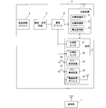
- FIG. 1 It is a figure which shows schematic structure of the radio
- a wireless communication module 1 shown in FIG. 1 includes a load 3 that includes a plurality of load elements, a vibration power generation device 4 that generates driving power for the load 3, and a power storage device that stores the generated power. 6, and a rectifying / transforming circuit 5 that is provided between the vibration power generation device 4 and the power storage device 6, rectifies the power generation current of the vibration power generation device 4, transforms it, and applies it to the power storage device 6.
- the vibration power generation device 4 is a power source using so-called environmental energy, and an example thereof is a power generation device using electret material. Since the vibration power generation device itself is a known technique, the detailed description thereof in this specification is omitted.
- a vibration power generation device using an electret material having a power generation amount of 20 to 100 ⁇ W and an output voltage of 30 to 80 Vp-p is employed, but the application of the present invention is not limited to the apparatus.
- a power generation device other than the vibration power generation device for example, a solar power generation device, a thermoelectric power generation device, an electromagnetic induction power generation (CT power generation) device, a bioelectric power generation device, etc. Good. Since these devices are also well-known techniques, their detailed description in this specification is omitted. Further, since the rectification / transformation circuit is a known technique, a detailed description thereof will be omitted.
- the power storage device 6 any power storage device can be adopted as long as it can store the power generated by the vibration power generation device 4 and can supply the power necessary for driving the load 3. .
- an electric double layer capacitor or other secondary battery can be employed as the electricity storage device 6.
- the load 3 includes two acceleration sensors 31 and 32 and wireless communication that wirelessly communicates detection values of the sensors to the base station 7 that exists outside the wireless communication module 1.
- a device 33 is included.
- the communication method of the wireless communication device 33 is not limited to a specific method, but as an example, it is preferable to employ a communication method with low power consumption conforming to the standard ZigBee.
- the acceleration sensors 31 and 32 are devices that detect accelerations in different predetermined directions at predetermined locations where the wireless communication module 1 is disposed, and are also well-known techniques in the present specification. The detailed explanation of is omitted.
- the wireless communication module 1 configured as described above integrally includes the vibration power generation device 4 and acceleration sensors 31 and 32 as load elements for acquiring information and a wireless communication device 33 as a further load element. Since the acquired information is wirelessly communicated to the outside, it functions as a self-supporting information collecting device. Therefore, the place where the wireless communication module 1 is placed is not particularly limited, and can be appropriately placed at any place, and information collection via the base station 7 can be easily realized. As described above, the wireless communication module 1 can be said to be a module having a very useful function. However, in order to drive the load 3 composed of a plurality of load elements mounted therein without any trouble, the power required for driving the load 3 is not limited. It must continue to be properly supplied. Therefore, the wireless communication module 1 according to the present invention is equipped with a control device 2 that performs control related to the power storage state of the power storage device 6 that supplies power to the load 3. Yes. Below, the control regarding the electrical storage state is demonstrated in detail.
- the control device 2 includes functional units such as a charge control unit 21, a discharge control unit 22, and a voltage monitoring unit 23. These functional units represent the control functions related to the power storage state of the power storage device 6 performed by the control device 2, and these functions correspond to the corresponding controls provided in the control device 2.
- the control device 2 is a computer, it may be realized by a control program executed on the computer, or may be realized by cooperation of the control circuit and the control program. Also good.
- the control device 2 may have functional units other than the functional units shown in FIG.
- the charging control unit 21 is a functional unit that controls the charging of the power storage device 6, and in order to drive the load 3 constantly and stably, the inter-terminal voltage of the power storage device 6 is guaranteed to be the minimum drive voltage. It is necessary to maintain above. Therefore, the charging control unit 21 controls charging from the vibration power generation device 4 as a power source to the power storage device 6 from the viewpoint of stable driving of the load 3. On the other hand, the discharge control unit 22 performs control related to discharging the electric power stored in the power storage device 6 for driving the load 3. In addition, the voltage monitoring unit 23 monitors the charge state of the power storage device 6, for example, the voltage across the terminals of the power storage device 6, in order to perform charge control by the charge control unit 21 and discharge control by the discharge monitoring unit 22 at appropriate timing.
- control device 2 includes the charge control unit 21 and the voltage monitoring unit 23 as described above, the control device 2 can correspond to the charge control device according to the present invention.
- these functional units are distinguished as shown in FIG. 1 for convenience of explanation, in a specific embodiment, as long as the above functions themselves are exhibited, the functional units are integrated, Alternatively, the functional unit may be subdivided.
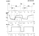
- FIG. 2A shows a control timing chart relating to the state of charge of the electricity storage device 6 realized by the voltage monitoring unit 23 and the charge control unit 21.
- an upper stage, a middle stage, and a lower stage are respectively shown in a timing chart schematically showing a charge / discharge operation of the electricity storage device 6, a transition of voltage between terminals of the electricity storage device 6, and a voltage monitoring unit 23.
- the transition of the determined voltage state of the power storage device 6 is shown, and the timing chart of each stage is arranged so that the time axis is common in FIG. 2A, and the timings at twelve locations t1 to t12 are shown. Marked.
- the voltage monitoring unit 23 is composed of a voltage monitoring IC chip, in which an upper limit monitoring voltage VH and a lower limit monitoring voltage VL are set, and the upper limit monitoring voltage VH has a higher correlation than the lower limit monitoring voltage VL. Have.
- the output of the voltage monitoring unit 23 is switched to the L signal state.
- the output of the voltage monitoring unit 23 is switched to the H signal state.
- the threshold value at which the voltage state determined by the voltage monitoring unit 23 is switched varies depending on the voltage fluctuation direction. In other words, the voltage state is performed based on a threshold value having hysteresis. The magnitude of this hysteresis, that is, the difference between the upper limit monitoring voltage VH and the lower limit monitoring voltage VL will be described later.
- FIG. 2A shows an enlarged view of the transition of the voltage between the terminals in the vicinity of the period t1-t4. Although timings t2 'and t4' not shown in FIG. 2A are shown in FIG. 2B, these will be sequentially described below including these timings.
- the voltage drop of the voltage between the terminals of the power storage device 6 caused by the drive current that starts to flow when the load 3 starts to be driven is referred to as “driving voltage drop”.
- This voltage drop during driving occurs from timing t1 to timing t2 ′ to be described later, and the voltage between the terminals interrupts the lower limit monitoring voltage VL at timing t2 in the middle. Note that in the period t1-t2, the output of the voltage monitoring unit 23 remains in the L signal state.
- Period t2-t3 In the period t2-t3, the power supply from the power storage device 6 to the load 3 is continued and the driving of the load 3 is continued. Therefore, the voltage drop during driving is completed at the timing t2 ′ in the middle, that is, even after the steep drive current rise itself at the start of load driving is completed, the voltage between the terminals of the electricity storage device 6 is compared with the voltage drop during driving. Will be moderate but will decrease over time.
- the period is a period from when the inter-terminal voltage interrupts the lower limit monitoring voltage VL at the timing t2 until the predetermined first period ⁇ tL elapses as described above.
- the predetermined first period ⁇ tL is a threshold for the voltage monitoring unit 23 to detect a state in which the voltage between the terminals is equal to or lower than the lower limit monitoring voltage VL, and the voltage between the terminals is equal to or lower than the lower limit monitoring voltage VL.
- the output of the voltage monitoring unit 23 is switched from the L signal state to the H signal state when the current state continues for the predetermined first period ⁇ tL or more, that is, when the timing t3 is reached.
- charging of the electricity storage device 6 is started at timing t3, triggered by the fact that the driving voltage drop in the electricity storage device 6 caused by driving the load 3 has fallen below the lower limit monitoring voltage VL for a predetermined period ⁇ tL. .
- the charging of the power storage device 6 is continued while the output of the voltage monitoring unit 23 remains in the H signal state.
- the voltage between the terminals of the power storage device 6 does not reach the upper limit monitoring voltage VH. Not reach. Therefore, the voltage between the terminals is increased by charging from the vibration power generation device 4 continued after the timing t3. As a result, the voltage between the terminals reaches the upper limit monitoring voltage VH at the timing t5, but the output of the voltage monitoring unit 23 remains in the H signal state even at that time.
- Period t5-t6 As described above, charging from the vibration power generation device 4 to the power storage device 6 is continued even at the timing t5, and the inter-terminal voltage is the upper limit monitoring voltage VH.
- the period is a period from when the inter-terminal voltage reaches the upper limit monitoring voltage VH at timing t5 until the predetermined second period ⁇ tH elapses.
- the predetermined second period ⁇ tH is a threshold for the voltage monitoring unit 23 to detect a state in which the inter-terminal voltage is equal to or higher than the upper limit monitoring voltage VH, and the inter-terminal voltage is equal to or higher than the upper limit monitoring voltage VH.
- the output of the voltage monitoring unit 23 is switched from the H signal state to the L signal state when the current state continues for the predetermined second period ⁇ tH or more, that is, when the timing t6 is reached. Charging from the vibration power generation device 4 to the power storage device 6 is terminated using the change in the output of the voltage monitoring unit 23 as a trigger.
- Period t6-t7 and subsequent period t7-t12 The period t6-t7 is a waiting period until the next load operation starts in the wireless communication module 1. Therefore, since the stored power of the power storage device 6 is not consumed during the period, the battery is maintained in a fully charged state.
- the next load operation may be started after elapse of a preset time, or may be started in accordance with an instruction from the outside of the module or based on a determination on the module side.
- the period t7-t12 corresponds to the next load operation.
- Each of the timings t7 to t12 corresponds to the timings t1 to t6 described above, and therefore a detailed description of each timing is omitted.
- the power storage device is based on the result of voltage monitoring by the voltage monitoring unit 23 in which two voltage thresholds having hysteresis, the lower limit monitoring voltage VL and the upper limit monitoring voltage VH are set. 6 charging timing is controlled. That is, a lower limit at which the threshold value for starting charging and the threshold value for stopping charging are set different from each other, and the voltage across the terminals of the power storage device 6 becomes a threshold value due to a voltage drop during driving that occurs when the load 3 is driven.
- the configuration is such that charging of the electricity storage device 6 is triggered when the voltage falls below the monitoring voltage VL.
- the energy consumption required for one load operation is extremely small in the current flow in which each load element mounted thereon is reduced in size.
- the upper limit monitoring voltage is 3.57 V
- the lower limit monitoring voltage is 3.4 V
- the capacity of the power storage device 6 is 0.033 F
- a series of operations of the load 3 acceleration sensors 31, 32 described above.
- the transition of the voltage between the terminals of the electricity storage device 6 at this time is indicated by a one-dot chain line L2 in the middle stage of FIG. 2A.
- the voltage difference before and after the load driving is only 0.02 V, and it can be said that it is not easy to accurately detect the voltage difference of 0.02 V in consideration of the error of voltage detection and the influence of noise.
- the drive voltage supplied to the load 3 must always exceed the drive voltage Vmin (see FIGS. 2A and 2B) for guaranteeing the drive.
- the load drive starts for the second time as shown by a one-dot chain line L2 in FIG. 2A.
- a voltage drop at the time of driving that occurs sometimes causes the voltage between the terminals of the electricity storage device 6 to fall below the driving voltage Vmin, and the stable driving of the load 3 may not be maintained.
- the wireless communication module 1 since the wireless communication module 1 according to the present invention has the above-described configuration related to charging, the power consumption of the storage capacitor 6 by driving the load 3, in other words, the storage capacitor 6 needs to be charged. It can be detected based on the voltage state of the voltage between the terminals due to the voltage drop during driving. Therefore, as shown by the solid line L1 in FIG. 2A, it is possible to reliably avoid that the voltage between the terminals of the power storage device 6 falls below the drive voltage Vmin in the process of driving the load 3. In particular, when the driving of the load 3 is continuously repeated, the determination of the charging timing of the power storage device 6 is extremely important in order to realize the driving constantly.
- the difference VH ⁇ VL between the inter-terminal voltage VH when the power storage device 6 is fully charged and the threshold voltage VL that triggers the start of charging is preferably determined so as to satisfy the following expression 1.
- VH ⁇ VL ⁇ Vd ⁇ Vn (Formula 1)
- Vd Voltage drop during driving
- ⁇ Vn Margin term for absorbing voltage fluctuation due to noise, etc.
- the voltage monitoring part 23 monitors the voltage state of the electrical storage device 6, the voltage between the terminals will become immediately below the lower limit monitoring voltage VL, or immediately after becoming the upper limit monitoring voltage VH or more.
- a configuration is adopted in which the signal is switched after the elapse of the predetermined first period ⁇ tL or the predetermined second period ⁇ tH without switching the H signal or the L signal indicating the voltage state.
- the predetermined first period ⁇ tL is preferably determined so as to satisfy the following expression 2.
- ⁇ T1 Time from the timing t2 when the voltage between the terminals has interrupted the lower limit monitoring voltage VL due to the voltage drop during driving to the timing t2 ′ when the voltage drop during driving is completed
- ⁇ T2 the voltage during driving due to the stop of driving the load from the above t2 ′
- the maximum value of the predetermined second period ⁇ tH is preferably set to such an extent that the continuous operation of the load 3 is not hindered, that is, the period t5-t7 shown in FIG. 2A is not unnecessarily long.
- the predetermined first period ⁇ tL and the predetermined second period ⁇ tH can each be set to about 30 ⁇ sec.
- FIG. 3 shows a modification of the charging control of the power storage device 6 by the control device 2 included in the wireless communication module 1 according to the present invention.
- the charging control of the power storage device 6 is performed after the load 3 performs a plurality of operations (in this example, two operations).
- the outline of the charge control will be described below.
- the amount of power required for one driving is the example shown in FIG. 2A by limiting the number of driving acceleration sensors to one, for example. It should be smaller than
- Period t21-t22 During the period, the first driving of the load 3 is performed. In this period, the voltage between the terminals of the electricity storage device 6 including the driving voltage drop does not become lower than the lower limit monitoring voltage VL.
- Period t22-t23 During the period, the driving of the load 3 is stopped. However, as described above, the inter-terminal voltage does not become lower than the lower limit monitoring voltage VL, so that the vibration power generation device 4 is not charged. Therefore, the inter-terminal voltage in the period is maintained at the voltage in a state where the voltage drop during driving is eliminated without returning to the voltage VH.
- the voltage monitoring unit 23 remains in the L signal state because the inter-terminal voltage does not become lower than the lower limit monitoring voltage VL for the predetermined first time ⁇ tL.
- Period t23-t24 At timing t23, the second driving of the load 3 is started. Therefore, after the timing t23, the voltage between the terminals greatly decreases due to the driving voltage drop, and becomes the lower limit monitoring voltage VL or less at the timing t24.
- Period t24-t25 This period is a period from the timing t24 until the predetermined first period ⁇ tL elapses. During this period, the inter-terminal voltage is below the lower limit monitoring voltage VL. Therefore, when the timing t25 is reached, the output of the voltage monitoring unit 23 is switched from the L signal state to the H signal state, and a trigger to start charging the power storage device 6 is generated.
- Period t25-t26 During this period, charging of the power storage device 6 is continued, and driving of the load 3 is stopped at timing t26.
- Period t27-t28 This period is a period from the timing t27 until the predetermined second period ⁇ tH elapses. In this period, the inter-terminal voltage is initially in the state of the upper limit monitoring voltage VH, and when the timing t28 is reached, the output of the voltage monitoring unit 23 is switched from the H signal state to the L signal state. Thus, a charging end trigger of 6 is generated.
- the charging control of the power storage device 6 may be started based on the driving voltage drop.
- the voltage between the terminals may not fall below the operating voltage Vmin during a plurality of operations. Desired.
- the electric power consumed by the load driving for two times is replenished by one charge control (charge control from the period t25 to t28), so that each time the load drive is performed. There is a possibility that the charging time until the fully charged state is made longer than in the case of performing the charging control.
- the VL is controlled so that the charge control is performed for each operation of the load 3. It can be said that it is preferable to adjust the value of.
- FIG. 4 shows a modification of the wireless communication module 1 according to the present invention.
- the load 3 includes dummy load circuits 34 and 35 in addition to the acceleration sensors 31 and 32 and the wireless communication device 33.
- the dummy load circuits 34 and 35 are not functional load elements that perform acquisition of specific data, wireless communication of the acquired data to the outside, and the like. It is a load element as a power consuming circuit for consuming. It is assumed that the power consumption capacity of the dummy load circuit 34 is smaller than that of the dummy load circuit 35.
- the dummy load circuits 34 and 35 are connected or cut off so that power can be supplied from the power storage device 6 by turning on and off the switches 36 and 37, respectively.
- the charging start timing of the power storage device 6 is reliably controlled. Is possible. For example, when the voltage drop during driving of the load 3 in which only the acceleration sensor 31 is driven as shown in FIG. 3 is small, the voltage between the terminals of the power storage device 6 is lower than the lower limit monitoring voltage VL in the first load driving. Since it does not become below, charge control of the electrical storage device 6 is not started.
- this modification by supplying power to the dummy load circuit 34 along with driving of the acceleration sensor 31, the power required for driving the entire load 3 can be increased and the voltage drop during driving can be increased. It becomes possible. As a result, even when a small load element is driven, it is possible to charge the power storage device 6 at an appropriate timing for each driving.
- Such power supply to the dummy load circuit 34 corresponds to the forced operation of the load according to the present invention.
- only the dummy load circuit 35 may be driven to ensure that the power storage device 6 is fully charged before driving the load 3.
- power is supplied to the dummy load circuit 35 immediately before the driving.
- the dummy load circuit 35 is a load element that causes a voltage drop during driving sufficient to generate a trigger for starting charging control of the power storage device 6 from its power consumption capability.
- the driving voltage Vmin is 2.0 V
- load elements constituting the load 3 are shown below.
- two types of wireless communication devices are shown in Table 1, and six types of sensors including acceleration sensors are shown in Table 2.
- the sum of the voltage drop during driving caused by each load element appears as a voltage drop amount of the entire load 3 to generate a trigger for starting the charge control of the storage sensor 6. Therefore, the upper limit monitoring voltage VH and the lower limit monitoring voltage VL in the control device 2 may be set in consideration of the types and number of wireless communication devices and sensors used.
- load element is one example, and various other load elements can be incorporated in the module according to the present invention.
- the predetermined upper limit voltage and the predetermined lower limit voltage Difference between the terminals of the power storage unit at the predetermined upper limit voltage is less than or equal to the predetermined lower limit voltage due to a voltage drop in the power storage unit that occurs when the load performs the predetermined operation.
- the amount of stored electricity can be made suitable for load driving at an appropriate timing without putting the power storage unit in an overcharged state, and charging is performed for each predetermined load operation.
- the charging time required for charging can be shortened as much as possible, and the next load operation after charging can be executed promptly.
- Such a configuration is particularly useful when the load repeatedly performs a predetermined operation.
- the voltage drop in the power storage unit is eliminated by stopping the load that the charge control unit is driving. After the voltage between the terminals recovers, the power supply from the power source may be controlled so that at least the difference between the voltage between the terminals at that time and the predetermined upper limit voltage is charged. In other words, when the load drive is stopped, the drive current stops flowing and the voltage drop that triggered the charging disappears, and as a result, the voltage between the terminals of the power storage unit rises and recovers. By charging until the voltage between the terminals after the increase becomes equal to or higher than the predetermined upper limit voltage, an appropriate amount of charging can be expected.
- the charging by the charging control unit may be performed after the load driving is stopped, and the voltage between the terminals of the power storage unit becomes equal to or lower than a predetermined lower limit voltage based on the voltage increase due to the elimination of the voltage drop.
- the charging may be started as quickly as possible, preferably before the load driving stops.
- the voltage monitoring unit is in a state where the voltage between the terminals of the power storage unit becomes equal to or lower than the predetermined lower limit voltage due to a voltage drop in the power storage unit when the load is driven.
- the power storage unit needs to be charged when it continues for a predetermined time or more.
- the load when the load performs a predetermined operation in the charge control device, a predetermined forced operation other than the predetermined operation is performed, and more current is consumed by the load than in the predetermined operation. You may make it further provide a forced drive part.
- the forcible driving unit causes the load to perform the predetermined forcible operation, if the voltage between the terminals of the power storage unit becomes equal to or lower than the predetermined lower limit voltage due to a voltage drop in the power storage unit, the charge control unit The power storage unit may be charged from the power source, and the voltage between the terminals of the power storage unit may be equal to or higher than the predetermined upper limit voltage.
- a trigger for charging the power storage unit is obtained by causing a voltage drop in the power storage unit by a forced operation that is an operation other than the predetermined operation.
- the current value consumed by the predetermined operation by the load is small, the amount of voltage drop due to the resistance component in the power storage unit and the load current at the time of driving the load is small, so the power storage unit should be charged. It becomes difficult to determine the timing to do appropriately. Therefore, in such a case, by using the voltage drop in the power storage unit by the forced drive unit, it is possible to cause a larger voltage drop, and thus a useful configuration from the viewpoint of charging at an appropriate timing It can be said.
- the charging timing is determined by appropriately mixing the predetermined operation and the forcing operation, so that there is no leakage. Appropriate charging can be realized.
- the present invention can also be understood from the side of a drive load module that includes the above-described charge control device and is configured with a driven load. That is, the present invention is a drive load module, and includes at least the charge control device described above, a power source that supplies power to the power storage unit, and a load that is supplied with drive power from the power storage unit. It may be configured. Thereby, it can be unified as a drive load module together with a power storage unit, a power source, and a load capable of continuously executing load-driven power supply.
- the driving load module is arranged such that one or more sensors for detecting a predetermined environmental parameter around the driving load module and the detection values of the one or more sensors are separated from the driving load module.
- a wireless transmission unit that wirelessly transmits to a predetermined reception unit. That is, by including the sensor and the wireless transmission unit of the detected value in the driving load module according to the present invention, the continuous power supply and sensor can be performed within the module without continuous power supply from the outside. Detection and transmission of detected values to the outside can be performed comprehensively, and the convenience of the module can be improved. Further, by integrating one or a plurality of sensors and the wireless communication unit as a load according to the present invention, the amount of voltage drop in the power storage unit that occurs during load driving can be increased. Even when the power is small, it is possible to more reliably detect a voltage drop in the power storage unit.
- the power source is a power source using predetermined environmental energy, and may include a vibration power generation device that converts external vibration energy into power or a solar power generation device that performs solar power generation. .
- a vibration power generation device that converts external vibration energy into power
- a solar power generation device that performs solar power generation.
- the power source includes one environmental power generation device that converts environmental energy into power, and further includes another environmental power generation device or a power supply device that can be discharged to the outside.
- a configuration including at least can be adopted.
- the power storage unit is supplied with power selectively from the one environmental power generation device and the power supply device or simultaneously from the one environmental power generation device and the power supply device. That is, a stable power supply to the load can be realized by adopting a so-called hybrid configuration including a plurality of power supply devices and power generation devices.
- a primary battery can be adopted as a power supply device that can be discharged to the outside.
- one environmental power generation device may be operated as a main power supply device, and when it becomes difficult to generate power, the primary battery may support power supply to the power storage unit. By doing in this way, a primary battery can be used as long as possible.
- another power storage device that stores power generated by another power generation device or an AC power supply device may be adopted as the “power supply device that can be discharged to the outside”. Note that the power supply to the power storage unit from one environmental power generation device and the power supply device is a simultaneous supply mode performed by both devices, even if one device performs a selective supply mode. In addition, each form may be appropriately executed alternately.
Landscapes
- Engineering & Computer Science (AREA)
- Power Engineering (AREA)
- Charge And Discharge Circuits For Batteries Or The Like (AREA)
- Secondary Cells (AREA)
Abstract
Description
タイミングt1より以前においては、負荷3は駆動されておらず、蓄電デバイス6は満充電状態にあり、故にその端子間電圧は上限監視電圧VHと同じ最大電圧値を示している。なお、このとき電圧監視部23の出力はL信号状態である。ここで、タイミングt1では蓄電デバイス6から負荷3に電力供給(放電)が開始され、負荷3を構成する加速度センサ31、32、無線通信デバイス33を駆動するのに必要な駆動電流が蓄電デバイス6から流れ始める。蓄電デバイス6は幾ばくかの内部抵抗を有することから、この駆動開始時の電流の急峻な立ち上がりとの相関によって蓄電デバイス6の端子間電圧が急激に電圧降下する。本明細書においては、負荷3を駆動開始した際に流れ始める駆動電流によって引き起こされる蓄電デバイス6の端子間電圧の電圧降下を、「駆動時電圧降下」と称することとする。なお、この駆動時電圧降下は、タイミングt1から後述するタイミングt2’までの間、生じており、その途中のタイミングt2においては当該端子間電圧が下限監視電圧VLを割り込む。なお、期間t1-t2では、電圧監視部23の出力はL信号状態のままである。
期間t2-t3では、蓄電デバイス6から負荷3への電力供給が引き続き行われ当該負荷3の駆動が継続されている。そのため、途中のタイミングt2’で駆動時電圧降下が完了し、すなわち負荷駆動開始時の急峻な駆動電流の立ち上がり自体は完了した後も、蓄電デバイス6の端子間電圧は駆動時電圧降下に比べては緩やかとなるが時間の経過とともに低下していく。そして、当該期間は、上記の通りタイミングt2で端子間電圧が下限監視電圧VLを割り込んでから所定第一期間ΔtLが経過するまでの期間である。この所定第一期間ΔtLは、電圧監視部23が、当該端子間電圧が下限監視電圧VL以下となっている状態を検知するための閾値であり、当該端子間電圧が下限監視電圧VL以下となっている状態が所定第一期間ΔtL以上続いたときに、すなわちタイミングt3に到達した時点で、電圧監視部23の出力が、L信号状態からH信号状態に切り替わる。
タイミングt3以降では、蓄電デバイス6から負荷3への電力供給が引き続き行われ当該負荷3の駆動が継続され、そしてタイミングt4に到達した時点で、当該負荷3の駆動が停止される。そのため、蓄電デバイス6からの放電はタイミングt4で終了し、以てその端子間電圧の降下もタイミングt4で終了することとなる。一方で、上記期間t2-t3において、電圧監視部23の出力が、L信号状態からH信号状態に切り替わったことをもって、タイミングt3以降では振動発電デバイス4から蓄電デバイス6への充電が開始される。そのため、蓄電デバイス6の端子間電圧の降下程度もある程度緩和されている。すなわち、負荷3の駆動により生じた蓄電デバイス6での駆動時電圧降下が下限監視電圧VLを所定期間ΔtL下回ったことをトリガーとして、タイミングt3において蓄電デバイス6への充電が開始されることになる。なお、この蓄電デバイス6への充電は、電圧監視部23の出力がH信号状態で有り続ける間、継続されることになる。
上記のとおりタイミングt4の時点で、負荷3の駆動が停止されることから、その駆動に要する駆動電流の蓄電デバイス6から負荷3側への流れが停止されることになる。そのため、期間t1-t2’で生じていた駆動時電圧降下分の電圧上昇がタイミングt4以降で生じる。この電圧上昇の過程において、途中のタイミングt4’で端子間電圧が下限監視電圧VLを通過するが、電圧監視部23の出力には変化はない。なお、期間t1-t4で負荷3を駆動していたため蓄電デバイス6の蓄電電力が消費され、その結果、上記電圧上昇が生じたとしても蓄電デバイス6の端子間電圧は上限監視電圧VHにまでは到達しない。そこで、タイミングt3以降継続されている振動発電デバイス4からの充電により、その端子間電圧の上昇が図られる。この結果、タイミングt5の時点で、当該端子間電圧が上限監視電圧VHに到達するが、その時点でも電圧監視部23の出力はH信号状態のままである。
上記の通りタイミングt5の時点でも振動発電デバイス4から蓄電デバイス6への充電は継続されており、その端子間電圧は上限監視電圧VHである。そして、当該期間は、タイミングt5で端子間電圧が上限監視電圧VHに到達してから所定第二期間ΔtHが経過するまでの期間である。この所定第二期間ΔtHは、電圧監視部23が、当該端子間電圧が上限監視電圧VH以上となっている状態を検知するための閾値であり、当該端子間電圧が上限監視電圧VH以上となっている状態が所定第二期間ΔtH以上続いたときに、すなわちタイミングt6に到達した時点で、電圧監視部23の出力が、H信号状態からL信号状態に切り替わる。この電圧監視部23の出力の変更をトリガーとして、振動発電デバイス4から蓄電デバイス6への充電が終了される。
期間t6-t7は、無線通信モジュール1において、次の負荷動作が始まるまでの待機期間である。したがって、当該期間では蓄電デバイス6の蓄電電力は消費されないため、満充電状態に維持される。なお、次の負荷動作は、予め設定された時間の経過後に開始されてもよく、また、モジュール外部からの指示に従って、もしくはモジュール側の判断に基づいて開始するようにしてもよい。ここで、期間t7-t12については、次の負荷動作に対応したものである。タイミングt7-t12のそれぞれは、上述したタイミングt1-t6に対応するものであり、そのため各タイミングに関する詳細な説明は割愛する。
VH-VL<Vd-ΔVn ・・・(式1)
Vd:駆動時電圧降下
ΔVn:ノイズ等による電圧変動を吸収するマージン項
このような差分VH-VLの設定を行うことで、負荷3が一連の動作(上述した加速度センサ31、32、無線通信デバイス33の駆動動作)を行う毎に、図2Aに示すように蓄電デバイス6の充電開始のトリガーが発生することになり、新たな負荷動作が開始される時点には蓄電デバイス6は満充電状態にされているため、無線通信モジュール1の安定的な連続動作を確保することが可能となる。
ΔtL<ΔT1+ΔT2・・・(式2)
ΔT1:駆動時電圧降下により端子間電圧が下限監視電圧VLを割り込んだタイミングt2から、駆動時電圧降下が完了したタイミングt2’までの時間
ΔT2:上記t2’から、負荷の駆動停止により駆動時電圧降下が解消することで端子間電圧が急上昇し下限監視電圧VLを超えたタイミングt4’までの時間
このように所定第一期間ΔtLを設定することで、上記のようにノイズ等の外乱の影響を排除しながら安定的な負荷3の駆動を確保することができる。また、所定第二期間ΔtHの最大値については、負荷3の連続動作が妨げられない程度に、すなわち図2Aで示す期間t5-t7がいたずらに長くならない程度に設定するのが好ましい。以上を踏まえ、例えば、所定第一期間ΔtL、所定第二期間ΔtHは、それぞれ約30μ秒に設定することができる。
図3に本発明に係る無線通信モジュール1に含まれる制御装置2による蓄電デバイス6の充電制御の変形例を示す。図3に示す例では、図2Aに示す例と異なり、負荷3が複数の動作(本例では2回の動作)を行った後に蓄電デバイス6の充電制御が行われる。以下、その充電制御の概略を説明する。なお、本変形例で行われる負荷3の駆動については、その一回当たりの駆動に要する電力量は、例えば駆動する加速度センサの台数を1台に制限する等して、図2Aに示した例と比べて小さいものとする。
当該期間では、負荷3の一回目の駆動が行われる。この期間では、駆動時電圧降下を含めて、蓄電デバイス6の端子間電圧は下限監視電圧VL以下とはならない。
(2)期間t22-t23
当該期間では負荷3の駆動が停止されるが、上記のとおり端子間電圧が下限監視電圧VL以下とはならないことから、振動発電デバイス4からの充電も行われない。したがって、当該期間での端子間電圧は、電圧VHに戻らずに駆動時電圧降下が解消した状態での電圧で維持される。
タイミングt23において、二回目の負荷3の駆動が開始される。そのため、タイミングt23以降で、端子間電圧が駆動時電圧降下によって大きく低下し、タイミングt24の時点で下限監視電圧VL以下となる。
当該期間は、タイミングt24以降、所定第一期間ΔtLが経過するまでの期間である。当該期間において、端子間電圧は下限監視電圧VLを下回った状態にある。したがって、タイミングt25に到達した時点で、電圧監視部23の出力が、L信号状態からH信号状態に切り替えられ、蓄電デバイス6の充電開始のトリガーが生成されることになる。
当該期間では蓄電デバイス6の充電が継続されるとともに、タイミングt26の時点で負荷3の駆動が停止される。
上記のとおり、タイミングt26で負荷3の駆動が停止されることから、当該期間では駆動時電圧降下が解消される。そのため、端子間電圧が急激に上昇し、更に蓄電デバイス6への充電が継続される。そして、タイミングt27の時点で端子間電圧が上限監視電圧VHに到達する。
当該期間は、タイミングt27以降、所定第二期間ΔtHが経過するまでの期間である。当該期間において、初めは端子間電圧は上限監視電圧VHとなった状態にあり、タイミングt28に到達した時点で、電圧監視部23の出力が、H信号状態からL信号状態に切り替えられ、蓄電デバイス6の充電終了のトリガーが生成されることになる。
図4に本発明に係る無線通信モジュール1の変形例を示す。図4に示す例では、図1に示す例と異なり、負荷3に、加速度センサ31、32および無線通信デバイス33の他に、ダミー負荷回路34、35が含まれる構成となっている。このダミー負荷回路34、35は、加速度センサ31等と異なり、特定のデータの取得や取得データの外部への無線通信等を行う機能的な負荷要素ではなく、蓄電デバイス6から供給される電力を消費するための電力消費回路として負荷要素である。消費電力能力は、ダミー負荷回路34の方がダミー負荷回路35よりも小さいものとする。そして、ダミー負荷回路34、35は、それぞれスイッチ36、37のON、OFFによって、蓄電デバイス6からの電力供給が可能となるように接続、又は遮断される。
本発明に係る制御装置2および無線通信モジュール1の実施例を以下に示す。
下限監視電圧VL:3.4V
蓄電デバイス6の内部抵抗:50Ω
このとき、負荷3の駆動時電流を10mAとなるように負荷3内の負荷要素(加速度センサ等)を選定する。そうすると、駆動時電圧降下は0.5Vとなり、電圧降下後の蓄電デバイス6の端子間電圧が3.07Vとなるため、外乱による端子間電圧の変動を考慮しても安定的な負荷3の駆動が期待できる。


2・・・・制御装置
3・・・・負荷
4・・・・振動発電デバイス
6・・・・蓄電デバイス
21・・・・充電制御部
22・・・・放電制御部
23・・・・電圧監視部
34、35・・・・ダミー負荷回路
Claims (11)
- 電源からの供給電力を蓄電するとともに、蓄電された電力を負荷に供給する蓄電部と、
前記蓄電部の端子間電圧が所定上限電圧以上であると該蓄電部は満充電状態にあると判断し、該蓄電部の端子間電圧が該所定上限電圧より低い所定下限電圧以下であると充電が必要と判断する電圧監視部と、
前記蓄電部の端子間電圧に基づいて、前記蓄電部への充電を制御する充電制御部と、
を備える、前記蓄電部への充電状態を制御する充電制御装置であって、
前記負荷が前記蓄電部からの電力供給によって駆動しているときに該蓄電部内の抵抗成分と負荷電流とに起因して該蓄電部内で生じる電圧降下により該蓄電部の端子間電圧が前記所定下限電圧以下になることで、前記電圧監視部が前記蓄電部の充電が必要と判断すると、前記充電制御部は、前記電源から前記蓄電部への充電を行い該蓄電部の端子間電圧を前記所定上限電圧以上とする、
充電制御装置。 - 前記負荷は、前記蓄電部からの電力供給によって単一の動作又は複数の動作からなる所定の動作を実行するものであって、
前記所定上限電圧と前記所定下限電圧との差分は、前記負荷が前記所定の動作を行っている際に生じる前記蓄電部内での電圧降下によって、該所定上限電圧にある該蓄電部の端子間電圧が、該所定下限電圧以下となるように設定される、
請求項1に記載の充電制御装置。 - 前記蓄電部の端子間電圧は、前記負荷が前記所定の動作を行っている間において、該負荷の駆動のために必要な所定の駆動電圧以上に維持される、
請求項2に記載の充電制御装置。 - 前記充電制御部は、駆動していた負荷が停止することで前記蓄電部内の電圧降下が解消してその端子間電圧が回復したときの端子間電圧と前記所定上限電圧との差分を少なくとも充電するように、前記電源からの電力供給を制御する、
請求項1から請求項3の何れか一項に記載の充電制御装置。 - 前記電圧監視部は、前記負荷が駆動しているときに前記蓄電部内での電圧降下により該蓄電部の端子間電圧が前記所定下限電圧以下になった状態が、所定時間以上継続したときに、前記蓄電部への充電が必要と判断する、
請求項1から請求項4の何れか一項に記載の充電制御装置。 - 前記負荷に、前記所定の動作以外の所定の強制動作を行わせて、該所定の動作の際より多くの電流を該負荷に消費させる強制駆動部を更に備え、
前記強制駆動部が前記負荷に前記所定の強制動作を行わせたときに前記蓄電部内での電圧降下により該蓄電部の端子間電圧が前記所定下限電圧以下になると、前記充電制御部は、前記電源から前記蓄電部への充電を行い該蓄電部の端子間電圧を前記所定上限電圧以上とする、
請求項2又は請求項3に記載の充電制御装置。 - 請求項1から請求項6の何れか一項に記載の充電制御装置と、
前記蓄電部に電力を供給する電源と、
前記蓄電部から駆動電力が供給される負荷と、
を備える、駆動負荷モジュール。 - 前記負荷は、
前記駆動負荷モジュールの周囲の所定の環境パラメータを検出する一又は複数のセンサと、
前記一又は複数のセンサの検出値を、前記駆動負荷モジュールとは離れて位置する所定の受信部へ無線で送信する無線送信部と、
を含む、請求項7に記載の駆動負荷モジュール。 - 前記電源は、外部からの振動エネルギーを電力変換する振動発電装置又は太陽光発電を行う太陽光発電装置を含む、
請求項7又は請求項8に記載の駆動負荷モジュール。 - 前記電源は、環境エネルギーを電力変換する一の環境型発電装置を含み、さらに、他の環境型発電装置又は外部に放電可能な電源装置からなる電力供給装置を少なくとも含むように構成され、
前記蓄電部は、前記一の環境型発電装置および前記電力供給装置から選択的に、もしくは該一の環境型発電装置および該電力供給装置から同時に電力供給される、
請求項7又は請求項8に記載の駆動負荷モジュール。 - 電源からの供給電力を蓄電するとともに、蓄電された電力を負荷に供給する蓄電部への充電状態を制御する充電制御方法であって、
前記蓄電部の端子間電圧が所定上限電圧以上であると該蓄電部は満充電状態にあると判断し、該蓄電部の端子間電圧が該所定上限電圧より低い所定下限電圧以下であると充電が必要と判断する判断基準に従い、前記充電状態の制御が行われ、
前記負荷が前記蓄電部からの電力供給によって駆動しているときに該蓄電部内の抵抗成分と負荷電流とに起因して該蓄電部内で生じる電圧降下により該蓄電部の端子間電圧が前記所定下限電圧以下になることを検出するステップと、
前記蓄電部の端子間電圧が前記所定下限電圧以下になると、前記電源から前記蓄電部への充電を行い該蓄電部の端子間電圧を前記所定上限電圧以上とするステップと、
を含んでなる充電制御方法。
Priority Applications (2)
| Application Number | Priority Date | Filing Date | Title |
|---|---|---|---|
| GB1315390.3A GB2502479B (en) | 2011-03-15 | 2011-03-23 | Charge control device and drive load module |
| US14/004,766 US9484764B2 (en) | 2011-03-15 | 2011-03-23 | Charge control device and drive load module |
Applications Claiming Priority (2)
| Application Number | Priority Date | Filing Date | Title |
|---|---|---|---|
| JP2011-056380 | 2011-03-15 | ||
| JP2011056380A JP5408162B2 (ja) | 2011-03-15 | 2011-03-15 | 充電制御装置、および駆動負荷モジュール |
Publications (1)
| Publication Number | Publication Date |
|---|---|
| WO2012124156A1 true WO2012124156A1 (ja) | 2012-09-20 |
Family
ID=46830264
Family Applications (1)
| Application Number | Title | Priority Date | Filing Date |
|---|---|---|---|
| PCT/JP2011/056962 Ceased WO2012124156A1 (ja) | 2011-03-15 | 2011-03-23 | 充電制御装置、および駆動負荷モジュール |
Country Status (4)
| Country | Link |
|---|---|
| US (1) | US9484764B2 (ja) |
| JP (1) | JP5408162B2 (ja) |
| GB (1) | GB2502479B (ja) |
| WO (1) | WO2012124156A1 (ja) |
Cited By (1)
| Publication number | Priority date | Publication date | Assignee | Title |
|---|---|---|---|---|
| JP2022049092A (ja) * | 2020-09-16 | 2022-03-29 | 株式会社東芝 | 状態監視システム及び状態監視プログラム |
Families Citing this family (9)
| Publication number | Priority date | Publication date | Assignee | Title |
|---|---|---|---|---|
| WO2015015527A1 (ja) * | 2013-07-29 | 2015-02-05 | パナソニックIpマネジメント株式会社 | 給電制御装置 |
| JP6239897B2 (ja) * | 2013-08-09 | 2017-11-29 | Kyb株式会社 | センサ装置 |
| US20160324077A1 (en) * | 2015-05-05 | 2016-11-10 | Helical Holdings, Llc | Portable hydroponic greenhouse assembly and method of using same |
| US10700527B2 (en) * | 2016-03-25 | 2020-06-30 | Sharp Kabushiki Kaisha | Power generation system, power conditioner, power control device, power control method, and power control program |
| KR102433146B1 (ko) | 2017-09-28 | 2022-08-17 | 주식회사 엘지에너지솔루션 | 배터리 셀의 스웰링을 방지하는 방법 및 이를 이용한 배터리 팩 |
| JP7306212B2 (ja) * | 2019-10-17 | 2023-07-11 | 日本ゼオン株式会社 | 電源装置 |
| CN112744101B (zh) * | 2020-12-25 | 2023-02-17 | 中国第一汽车股份有限公司 | 充放电控制系统、方法及交通工具 |
| KR102434036B1 (ko) * | 2021-06-17 | 2022-08-19 | 삼성전자주식회사 | 보조 전원 장치의 수명을 위한 충전 전압 제어 방법 및 이를 수행하는 스토리지 장치 |
| TWI908444B (zh) * | 2024-11-05 | 2025-12-11 | 群光電子股份有限公司 | 觸控板裝置 |
Citations (3)
| Publication number | Priority date | Publication date | Assignee | Title |
|---|---|---|---|---|
| JPH1066271A (ja) * | 1996-08-12 | 1998-03-06 | Toshiba Home Technol Corp | 充電制御装置およびこの充電制御装置を備えた電気ポット |
| JP2005242441A (ja) * | 2004-02-24 | 2005-09-08 | Tateyama Kagaku Kogyo Kk | 事象検知システム |
| JP2008539561A (ja) * | 2005-04-28 | 2008-11-13 | ローズマウント インコーポレイテッド | フィールド装置用の充電システム |
Family Cites Families (7)
| Publication number | Priority date | Publication date | Assignee | Title |
|---|---|---|---|---|
| JPS6154820A (ja) * | 1984-08-23 | 1986-03-19 | シャープ株式会社 | 光発電システムの直交変換装置 |
| JPH06323154A (ja) | 1993-05-11 | 1994-11-22 | Isuzu Motors Ltd | 車両の電力制御装置 |
| US6301198B1 (en) | 1997-12-11 | 2001-10-09 | Citizen Watch Co., Ltd. | Electronic timepiece |
| JP2004236381A (ja) | 2003-01-28 | 2004-08-19 | Honda Motor Co Ltd | 蓄電池の充放電制御装置および車両用蓄電池の充放電制御装置 |
| WO2007086472A1 (ja) * | 2006-01-27 | 2007-08-02 | Sharp Kabushiki Kaisha | 電力供給システム |
| US7671567B2 (en) * | 2007-06-15 | 2010-03-02 | Tesla Motors, Inc. | Multi-mode charging system for an electric vehicle |
| US20110193518A1 (en) * | 2010-02-10 | 2011-08-11 | James Wright | Battery override |
-
2011
- 2011-03-15 JP JP2011056380A patent/JP5408162B2/ja not_active Expired - Fee Related
- 2011-03-23 WO PCT/JP2011/056962 patent/WO2012124156A1/ja not_active Ceased
- 2011-03-23 US US14/004,766 patent/US9484764B2/en active Active
- 2011-03-23 GB GB1315390.3A patent/GB2502479B/en active Active
Patent Citations (3)
| Publication number | Priority date | Publication date | Assignee | Title |
|---|---|---|---|---|
| JPH1066271A (ja) * | 1996-08-12 | 1998-03-06 | Toshiba Home Technol Corp | 充電制御装置およびこの充電制御装置を備えた電気ポット |
| JP2005242441A (ja) * | 2004-02-24 | 2005-09-08 | Tateyama Kagaku Kogyo Kk | 事象検知システム |
| JP2008539561A (ja) * | 2005-04-28 | 2008-11-13 | ローズマウント インコーポレイテッド | フィールド装置用の充電システム |
Cited By (2)
| Publication number | Priority date | Publication date | Assignee | Title |
|---|---|---|---|---|
| JP2022049092A (ja) * | 2020-09-16 | 2022-03-29 | 株式会社東芝 | 状態監視システム及び状態監視プログラム |
| JP7414679B2 (ja) | 2020-09-16 | 2024-01-16 | 株式会社東芝 | 状態監視システム、状態監視プログラム及びコントローラ |
Also Published As
| Publication number | Publication date |
|---|---|
| JP5408162B2 (ja) | 2014-02-05 |
| GB201315390D0 (en) | 2013-10-16 |
| JP2012196001A (ja) | 2012-10-11 |
| US20140002029A1 (en) | 2014-01-02 |
| GB2502479A (en) | 2013-11-27 |
| US9484764B2 (en) | 2016-11-01 |
| GB2502479B (en) | 2017-04-12 |
Similar Documents
| Publication | Publication Date | Title |
|---|---|---|
| JP5408162B2 (ja) | 充電制御装置、および駆動負荷モジュール | |
| CN104283297B (zh) | 独立电源系统 | |
| JP6152919B1 (ja) | エナジーハーベスト端末 | |
| JP5310662B2 (ja) | 電圧変換回路、および電子機器 | |
| EP2413465A1 (en) | Battery heating circuit | |
| TW201822423A (zh) | 能量採集系統與能量採集系統的控制方法 | |
| US20120091968A1 (en) | Method and apparatus for tracking maximum power point | |
| JPWO2015115654A1 (ja) | センサノード、及びセンサノードの制御方法 | |
| JP5790197B2 (ja) | 画像形成装置および電源制御方法 | |
| JP6145741B1 (ja) | エナジーハーベスト端末 | |
| CN101951033A (zh) | 基于无线传感器网络的节点智能供电装置及方法 | |
| JP6357966B2 (ja) | 電源制御装置および電子装置 | |
| JP2014143087A (ja) | 電池劣化計測装置および方法 | |
| CN105141009B (zh) | 电源管理方法、电源管理芯片和电子系统 | |
| JP5960641B2 (ja) | 充電装置 | |
| CN110768537B (zh) | 一种双边反馈和控制dsr架构 | |
| US20150280554A1 (en) | Multiple power path management with micro-energy harvesting | |
| CN103384072B (zh) | 具有充电放电控制电路的电子设备 | |
| CN102386671B (zh) | 用于无线通信系统的电源设备和方法及传感器组件 | |
| JP2016226130A (ja) | 充電装置、電子機器、及び充電方法 | |
| JP2007209056A (ja) | 蓄電装置 | |
| CN100440612C (zh) | 一种光电充电器、充电方法及其应用的电子产品 | |
| JP2019193524A (ja) | 太陽電池充電装置および太陽電池充電方法 | |
| JP2013247716A (ja) | 二次電池充電システム及び二次電池充電方法 | |
| CN204068336U (zh) | 一种充电电路 |
Legal Events
| Date | Code | Title | Description |
|---|---|---|---|
| 121 | Ep: the epo has been informed by wipo that ep was designated in this application |
Ref document number: 11860760 Country of ref document: EP Kind code of ref document: A1 |
|
| ENP | Entry into the national phase |
Ref document number: 1315390 Country of ref document: GB Kind code of ref document: A Free format text: PCT FILING DATE = 20110323 |
|
| WWE | Wipo information: entry into national phase |
Ref document number: 1315390.3 Country of ref document: GB |
|
| WWE | Wipo information: entry into national phase |
Ref document number: 14004766 Country of ref document: US |
|
| NENP | Non-entry into the national phase |
Ref country code: DE |
|
| 122 | Ep: pct application non-entry in european phase |
Ref document number: 11860760 Country of ref document: EP Kind code of ref document: A1 |