WO2012124122A1 - Line connection device, line connection method, and program - Google Patents
Line connection device, line connection method, and program Download PDFInfo
- Publication number
- WO2012124122A1 WO2012124122A1 PCT/JP2011/056464 JP2011056464W WO2012124122A1 WO 2012124122 A1 WO2012124122 A1 WO 2012124122A1 JP 2011056464 W JP2011056464 W JP 2011056464W WO 2012124122 A1 WO2012124122 A1 WO 2012124122A1
- Authority
- WO
- WIPO (PCT)
- Prior art keywords
- connection
- hold
- holdee
- line
- operator
- Prior art date
Links
Images


Classifications
-
- H—ELECTRICITY
- H04—ELECTRIC COMMUNICATION TECHNIQUE
- H04W—WIRELESS COMMUNICATION NETWORKS
- H04W4/00—Services specially adapted for wireless communication networks; Facilities therefor
- H04W4/16—Communication-related supplementary services, e.g. call-transfer or call-hold
-
- H—ELECTRICITY
- H04—ELECTRIC COMMUNICATION TECHNIQUE
- H04M—TELEPHONIC COMMUNICATION
- H04M3/00—Automatic or semi-automatic exchanges
- H04M3/42—Systems providing special services or facilities to subscribers
- H04M3/428—Arrangements for placing incoming calls on hold
-
- H—ELECTRICITY
- H04—ELECTRIC COMMUNICATION TECHNIQUE
- H04M—TELEPHONIC COMMUNICATION
- H04M2203/00—Aspects of automatic or semi-automatic exchanges
- H04M2203/20—Aspects of automatic or semi-automatic exchanges related to features of supplementary services
- H04M2203/2088—Call or conference reconnect, e.g. resulting from isdn terminal portability
-
- H—ELECTRICITY
- H04—ELECTRIC COMMUNICATION TECHNIQUE
- H04M—TELEPHONIC COMMUNICATION
- H04M3/00—Automatic or semi-automatic exchanges
- H04M3/42—Systems providing special services or facilities to subscribers
- H04M3/42025—Calling or Called party identification service
- H04M3/42034—Calling party identification service
- H04M3/42059—Making use of the calling party identifier
-
- H—ELECTRICITY
- H04—ELECTRIC COMMUNICATION TECHNIQUE
- H04M—TELEPHONIC COMMUNICATION
- H04M3/00—Automatic or semi-automatic exchanges
- H04M3/42—Systems providing special services or facilities to subscribers
- H04M3/42025—Calling or Called party identification service
- H04M3/42085—Called party identification service
- H04M3/42102—Making use of the called party identifier
-
- H—ELECTRICITY
- H04—ELECTRIC COMMUNICATION TECHNIQUE
- H04M—TELEPHONIC COMMUNICATION
- H04M3/00—Automatic or semi-automatic exchanges
- H04M3/42—Systems providing special services or facilities to subscribers
- H04M3/48—Arrangements for recalling a calling subscriber when the wanted subscriber ceases to be busy
Landscapes
- Engineering & Computer Science (AREA)
- Signal Processing (AREA)
- Computer Networks & Wireless Communication (AREA)
- Telephonic Communication Services (AREA)
Abstract
A line connection device is configured to: place on-hook a holding person terminal of a holding person who has placed a line on hold, and send the audio of the person on hold for whom the line was placed on hold to the holding person terminal, as well as associate and record holding person identification data for the holding person and person-on-hold identification data for the person on hold in a connection control database for managing line holds and releases of said holds, when a hold is recognized on a connected line; and, if disconnection of the held line is recognized, obtains from the holding person for whom the line was disconnected connection conditions locking the line so that a reconnection request from the same person on hold who was disconnected while on hold is answered by the holding person terminal, stores same in the connection control database in association with the holding person identification data and, in accordance with the reconnection request by the same person on hold, browses the connection control database and causes the holding person terminal to answer, in accordance with the obtained connection conditions and on the basis of the holding person identification data associated with the person-on-hold identification data.
Description
本発明は、保留後に切断された通話回線の再接続に関する。
The present invention relates to reconnection of a telephone line disconnected after being put on hold.
従来より、電話対応において、発呼者からの接続要求応じて着呼し、発呼者からの質問、要望などに対応するために回線が保留状態となった際に、その保留状態を被保留者から解除するための種々の提案がなされている。
Conventionally, when a call is received in response to a connection request from a caller and the line is put on hold to respond to a question or request from the caller, the hold state is held. Various proposals have been made for canceling the system.
例えば、被保留者側で特番をダイヤル、保留解除要求信号を送出する等によって保留者の電話機のスピーカーをオンにし音声にて保留者との通話を可能とする技術、被保留者によって録音されたメッセージを保留者の電話番号に対応付けた技術、被保留者が保留中の通話の切断を通知する技術などが知られている。
For example, a technology that enables a call to the holder by voice by turning on the speaker of the holder's phone by dialing a special number on the holdee side, sending a hold release request signal, etc., recorded by the holdee A technique in which a message is associated with a telephone number of a holdee, a technique in which a holdee notifies the disconnection of a call on hold, and the like are known.
また、無線通信端末の通信状態又は電池残量に応じて保留に設定後、所定時間以内に再接続可能となった場合に保留解除して通信状態を復旧する技術、保留中に被保留者側が切断した際に、その被保留者の電話番号を記憶し、保留者側から再接続できるようにした技術、予め占有状態で接続し、切断後には接続に係る占有文字列の一致で再接続する技術などが提案されている。
In addition, after setting to hold depending on the communication status of the wireless communication terminal or the remaining battery level, the technology to release the hold and restore the communication status when reconnection is possible within a predetermined time, When disconnecting, the phone number of the holdee is memorized, and the technology that enables reconnection from the holdee side, connect in advance in the occupied state, and after disconnection, reconnect by matching the occupied character string related to the connection Technologies etc. have been proposed.
上述した従来技術では、通話を再開した際には、保留者と被保留者との間で回線の切断後に再接続するための種々の操作、回線の切断前後の状況について会話するなどが必要であった。
In the above-described prior art, when the call is resumed, it is necessary to perform various operations for reconnection after the line is disconnected between the holdee and the holdee, and a conversation about the situation before and after the line is disconnected. there were.
コールセンタなど顧客の質問、要望などに対応するオペレータ業務の場合、近年広く普及した電話機を用いた問合せの対応が通常に行われている。このようなオペレータ業務では、問合せに対応するために回線を保留することがある。この保留中に、被保留者である顧客の電話機の使用状況あるいは顧客の意志によって、顧客の電話機側から一旦回線が切断されてしまうことがある。そして、少し時間が経過してから、再び顧客が携帯電話機を用いて再接続してくる場合がある。すると、通常、回線接続装置は顧客対応履歴を参照し、保留状態にしたオペレータに再接続することが多い。
In the case of operator duties such as call centers that respond to customer questions and requests, inquiries using telephones that have become widespread in recent years are usually performed. In such an operator task, a line may be put on hold to respond to an inquiry. During this hold, the line may be temporarily disconnected from the customer's telephone side depending on the usage status of the customer's telephone or the customer's will. Then, after a little time has passed, the customer may reconnect using the mobile phone again. Then, usually, the line connection device often refers to the customer response history and reconnects to an on-hold operator.
一方、保留中のオペレータは、問合せのための作業中であるため、例えば、顧客側から回線が切断されたことを知らずに、作業に集中、又は調査のため離席していることがある。そのため、顧客の発話が再接続されてしまうと、オペレータは、仕掛り中の作業や調査を一旦中止して、わざわざ着呼応答操作や、顧客と対話するなどの対応を迫られることになる。しかし、再接続による顧客への対応によって作業が中断されてしまうことは、オペレータは作業に集中できず、オペレータの顧客対応の効率化の観点で問題があった。また、オペレータは、回線がいつ切断されたのか、どのような状況で切断されたのか状況を把握することが困難な場合があり、回線保留にして現在行なっている作業が結局無駄になるかもしれない。また、再接続の際の顧客への適切な対応がしにくいと言った問題があった。
On the other hand, since the operator on hold is in the process of making an inquiry, for example, the customer may not be aware that the line has been disconnected, concentrate on the work, or leave the office for investigation. For this reason, when the customer's utterance is reconnected, the operator temporarily stops the work or investigation in progress, and is forced to take action such as an incoming call response operation or a dialogue with the customer. However, the fact that the work is interrupted due to the response to the customer due to the reconnection causes the operator to concentrate on the work, and there is a problem in terms of the efficiency of the operator's customer response. In addition, it may be difficult for the operator to grasp when the line is disconnected and under what circumstances, and the work currently being performed with the line held may eventually be wasted. Absent. In addition, there was a problem that it was difficult to respond appropriately to customers during reconnection.
開示の技術は、回線の保留及び該保留の解除を管理するための接続制御データベースを格納する記憶部と、前記保留を認知すると、前記回線を保留した保留者の保留者端末をオンフックにして該回線が保留された被保留者の音声を該保留者端末に送出するようにして、前記接続制御データベースに、該保留者を識別する保留者識別情報と、該被保留者を識別する被保留者識別情報とを対応付けて記録する保留/解除認知部と、前記保留/解除認知部によって保留された前記回線の切断が認知されると、該回線を切断された前記保留者識別情報に基づく前記保留者から、保留中の切断後になされた同一被保留者による再接続要求を前記保留者端末が着信するために回線をロックする接続条件を取得して、該保留者識別情報に対応付けて前記接続制御データベースに格納するロック設定部と、前記同一被保留者による再接続要求に応じて、前記記憶部に格納された前記接続制御データベースを参照し、該再接続要求に指定される前記被保留者識別情報に対応付けられた前記接続条件に従って、該被保留者識別情報に対応付けられた前記保留者識別情報に基づいて、前記保留者端末に着信させる接続制御部と、を有する回線接続装置のように構成される。
The disclosed technology includes a storage unit that stores a connection control database for managing line hold and release of the hold, and recognizing the hold, sets the holder terminal of the holder holding the line on hook to The voice of the holdee whose line is put on hold is sent to the holdee terminal, the hold control information for identifying the holdee in the connection control database, and the holdee identifying the holdee The hold / release recognition unit that records the identification information in association with each other, and when the disconnection of the line held by the hold / release recognition unit is recognized, the line based on the holder identification information that has been disconnected. From the holder, obtain a connection condition for locking the line in order for the holder terminal to receive a reconnection request by the same holder who was made after disconnection on hold, and associate it with the holder identification information Contact The lock setting unit stored in the control database, and the connectionee database specified in the reconnection request by referring to the connection control database stored in the storage unit in response to the reconnection request by the same holdee A connection control unit for causing the holdee terminal to receive a call based on the holdee identification information associated with the holdee identification information in accordance with the connection condition associated with the identification information. Configured as follows.
また、上記課題を解決するための手段として、コンピュータによって実現される回線接続方法、コンピュータに上記回線接続装置として機能させるプログラム、及び、そのプログラムを記録した記録媒体とすることもできる。
Further, as means for solving the above problems, a line connection method realized by a computer, a program for causing a computer to function as the line connection device, and a recording medium on which the program is recorded can be used.
開示の技術では、通話を保留した際に、保留者端末をオンフックで被保留者の音声を聞けるようにしておくことで、通話の保留中に切断された際に、保留者は同一被保留者からの再接続要求に対する接続条件を適切に設定しておくことができる。そして、再接続要求があった場合は、設定された接続条件に従って回線接続させることができる。
In the disclosed technology, when a call is put on hold, the holder terminal can listen to the holdee's voice on-hook, so that when the call is disconnected while the call is put on hold, the holdee is the same holdee. The connection condition for the reconnection request from can be set appropriately. When there is a reconnection request, the line can be connected according to the set connection conditions.
以下、本発明の実施の形態を図面に基づいて説明する。図1は、本実施例に係るシステム構成例を示す図である。図1に示すシステム1000は、サーバ100と、複数の顧客端末9と、複数のオペレータ端末200とを有し、サーバ100は、公衆回線網5を介して顧客端末9と接続され、ネットワーク6を介してオペレータ端末200に接続されている。
Hereinafter, embodiments of the present invention will be described with reference to the drawings. FIG. 1 is a diagram illustrating a system configuration example according to the present embodiment. A system 1000 shown in FIG. 1 includes a server 100, a plurality of customer terminals 9, and a plurality of operator terminals 200. The server 100 is connected to the customer terminal 9 via the public line network 5, and To the operator terminal 200.
サーバ100は、業務に係るコールセンタに設置される回線接続装置であり、問合せを行う顧客の顧客端末9と、問合せに応じるオペレータのオペレータ端末200との通信に係る接続及び切断処理を行う。サーバ100は、接続制御処理部40と、通話処理部50と、再接続処理部60とを有し、公衆回線網5からの顧客端末9の接続要求が再接続に寄るものか通常接続であるかを判断し、オペレータとの通話を仲介する。また、サーバ100は、記憶部30に、オペレータDB(DataBase)31と、接続制御DB32とを格納する。各部40、50、及び60と、DB31及び32とについては後述される。
The server 100 is a line connection device installed in a call center related to business, and performs connection and disconnection processing related to communication between a customer terminal 9 of a customer who makes an inquiry and an operator terminal 200 of an operator who responds to the inquiry. The server 100 includes a connection control processing unit 40, a call processing unit 50, and a reconnection processing unit 60. The connection request for the customer terminal 9 from the public line network 5 is related to reconnection or normal connection. And mediate the call with the operator. The server 100 also stores an operator DB (DataBase) 31 and a connection control DB 32 in the storage unit 30. Each part 40, 50, and 60 and DB31 and 32 are mentioned later.
本実施例において、再接続とは、所定時間内の直前の回線接続の保留状態で顧客端末9から回線が切断された後に同一顧客端末9から接続要求を受信したことを言う。本実施例における再接続では、サーバ100からの保留応答指示に応じて、オペレータ端末200が、オペレータの応答着信の操作を不要として自動的に着信する。
In this embodiment, the reconnection means that a connection request is received from the same customer terminal 9 after the line is disconnected from the customer terminal 9 in the pending state of the previous line connection within a predetermined time. In the reconnection in the present embodiment, in response to a hold response instruction from the server 100, the operator terminal 200 automatically receives an operation without receiving an operator's response reception operation.
また、通常接続とは、所定時間内において、同一顧客端末9からの接続要求を受信しておらず、最初の接続要求を受信したことを言い、オペレータが着信応答の操作を行うことによって呼の着信となる。
In addition, the normal connection means that a connection request from the same customer terminal 9 has not been received within a predetermined time, and the first connection request has been received. Receive an incoming call.
各オペレータ端末200は、顧客からの問合せに対応するオペレータによって使用される端末であり携帯電話機、又は電話機能を有する移動通信端末などであり、サーバ100を介して顧客端末9と通信及び対話するためのオペレータ用処理部70を有する。
Each operator terminal 200 is a terminal used by an operator who responds to an inquiry from a customer, and is a mobile phone or a mobile communication terminal having a telephone function, and communicates and interacts with the customer terminal 9 via the server 100. The operator processing unit 70 is provided.
本実施例に係るサーバ100は、例えば、図2に示すようなハードウェア構成を有する。図2は、サーバのハードウェア構成を示す図である。
The server 100 according to the present embodiment has a hardware configuration as shown in FIG. 2, for example. FIG. 2 is a diagram illustrating a hardware configuration of the server.
図2において、サーバ100は、コンピュータによって制御される端末であって、CPU(Central Processing Unit)11と、メモリユニット12と、表示ユニット13と、出力ユニット14と、入力ユニット15と、通信ユニット16と、記憶装置17と、ドライバ18とを有し、システムバスBを介して互いに接続される。
In FIG. 2, a server 100 is a terminal controlled by a computer, and includes a CPU (Central Processing Unit) 11, a memory unit 12, a display unit 13, an output unit 14, an input unit 15, and a communication unit 16. And a storage device 17 and a driver 18, which are connected to each other via a system bus B.
CPU11は、メモリユニット12に格納されたプログラムに従ってサーバ100を制御する。メモリユニット12には、RAM(Random Access Memory)及びROM(Read-Only Memory)等が用いられ、CPU11にて実行されるプログラム、CPU11での処理に必要なデータ、CPU11での処理にて得られたデータ等を格納する。また、メモリユニット12の一部の領域が、CPU11での処理に利用されるワークエリアとして割り付けられている。
The CPU 11 controls the server 100 according to the program stored in the memory unit 12. The memory unit 12 uses RAM (Random Access Memory), ROM (Read-Only Memory), etc., and is obtained by a program executed by the CPU 11, data necessary for processing by the CPU 11, and processing by the CPU 11. Stored data. A part of the memory unit 12 is allocated as a work area used for processing by the CPU 11.
表示ユニット13は、CPU11の制御のもとに必要な各種情報を表示する。出力ユニット14は、プリンタ等を有し、管理者からの指示に応じて各種情報を出力するために用いられる。入力ユニット15は、マウス、キーボード等を有し、管理者がサーバ100が処理を行なうための必要な各種情報を入力するために用いられる。
The display unit 13 displays various information required under the control of the CPU 11. The output unit 14 includes a printer or the like, and is used for outputting various types of information according to instructions from the administrator. The input unit 15 includes a mouse, a keyboard, and the like, and is used by an administrator to input various information necessary for the server 100 to perform processing.
通信ユニット16は、局終端装置16aと、ネットワーク通信部16bとを有する。局終端装置16aは、サーバ100が着呼した顧客端末9からのアナログ音声をデジタル信号に変換する装置である。ネットワーク通信部16bは、例えばイーサネット(登録商標)などのLAN(Local Area Network)に接続し、オペレータ端末200との通信を行う装置である。通信ユニット16は、CPU11の制御の下、顧客端末9とオペレータ端末200間の通信を制御する。
The communication unit 16 includes a station termination device 16a and a network communication unit 16b. The station termination device 16a is a device that converts analog voice from the customer terminal 9 received by the server 100 into a digital signal. The network communication unit 16b is a device that communicates with the operator terminal 200 by connecting to a LAN (Local Area Network) such as Ethernet (registered trademark). The communication unit 16 controls communication between the customer terminal 9 and the operator terminal 200 under the control of the CPU 11.
記憶装置17には、例えば、ハードディスクユニットが用いられ、各種処理を実行するプログラム等のデータを格納する。メモリユニット12及び/又は記憶装置17の一部が図1に示す記憶部30に相当する。
For example, a hard disk unit is used as the storage device 17 and stores data such as programs for executing various processes. A part of the memory unit 12 and / or the storage device 17 corresponds to the storage unit 30 shown in FIG.
サーバ100によって行われる処理を実現するプログラムは、例えば、CD-ROM(Compact Disc Read-Only Memory)等の記憶媒体19によってサーバ100に提供される。即ち、プログラムが保存された記憶媒体19がドライバ18にセットされると、ドライバ18が記憶媒体19からプログラムを読み出し、その読み出されたプログラムがシステムバスBを介して記憶装置17にインストールされる。そして、プログラムが起動されると、記憶装置17にインストールされたプログラムに従ってCPU11がその処理を開始する。尚、プログラムを格納する媒体としてCD-ROMに限定するものではなく、コンピュータが読み取り可能な媒体であればよい。コンピュータ読取可能な記憶媒体として、CD-ROMの他に、DVDディスク、USBメモリ等の可搬型記録媒体、フラッシュメモリ等の半導体メモリであっても良い。
A program that realizes processing performed by the server 100 is provided to the server 100 by a storage medium 19 such as a CD-ROM (Compact Disc Read-Only Memory). That is, when the storage medium 19 storing the program is set in the driver 18, the driver 18 reads the program from the storage medium 19, and the read program is installed in the storage device 17 via the system bus B. . When the program is activated, the CPU 11 starts its processing according to the program installed in the storage device 17. The medium for storing the program is not limited to a CD-ROM, and any medium that can be read by a computer may be used. As a computer-readable storage medium, in addition to a CD-ROM, a portable recording medium such as a DVD disk or a USB memory, or a semiconductor memory such as a flash memory may be used.
図3は、サーバの機能構成例を示す図である。図3に示すサーバ100は、CPU11が対応するプログラムを実行することによって、接続制御処理部40、通話処理部50、及び再接続処理部60の各々を実現する。
FIG. 3 is a diagram illustrating a functional configuration example of the server. The server 100 illustrated in FIG. 3 realizes each of the connection control processing unit 40, the call processing unit 50, and the reconnection processing unit 60 by the CPU 11 executing a corresponding program.
接続制御処理部40は、接続制御DB32を参照することによって、局終端装置16aを介して顧客端末9から接続又は切断に係る処理を通話処理部50又は再接続処理部60に行わせる制御部である。
The connection control processing unit 40 is a control unit that causes the call processing unit 50 or the reconnection processing unit 60 to perform processing related to connection or disconnection from the customer terminal 9 via the station termination device 16a by referring to the connection control DB 32. is there.
通常接続である場合、接続制御処理部40は、通話処理部50に対応する処理を行わせる。一方、保留中に通話が切断された場合、接続制御処理部40は、同一顧客端末9からの再接続時に保留状態で着信(以下、保留着信と言う)するか、又は、呼び出し音で通知するかのオペレータの選択に応じて、オペレータ端末200の回線をロックする処理を行う。同一顧客端末9からの再接続を認知した場合、接続制御処理部40は、再接続処理部60に保留状態を保持した再接続処理を行わせる。
In the case of normal connection, the connection control processing unit 40 causes the call processing unit 50 to perform a corresponding process. On the other hand, when the call is disconnected during the hold, the connection control processing unit 40 receives the call in a hold state (hereinafter referred to as a hold incoming call) when reconnecting from the same customer terminal 9, or notifies it by a ringing tone. In response to the operator's selection, processing for locking the line of the operator terminal 200 is performed. When reconnection from the same customer terminal 9 is recognized, the connection control processing unit 40 causes the reconnection processing unit 60 to perform reconnection processing that holds the pending state.
接続制御処理部40は、接続確認部41と、保留/解除認知部42と、ロック設定部43と、ロック管理部44とを有する。
The connection control processing unit 40 includes a connection confirmation unit 41, a hold / release recognition unit 42, a lock setting unit 43, and a lock management unit 44.
接続確認部41は、記憶部30に格納されている接続制御DB32を参照することによって、通常接続であるか、又は保留状態の再接続であるかを確認する処理部である。
The connection confirmation unit 41 is a processing unit that refers to the connection control DB 32 stored in the storage unit 30 to confirm whether the connection is a normal connection or a reconnection in a suspended state.
保留/解除認知部42は、回線の保留、保留解除、又は切断を認知し、オペレータDB31及び接続制御DB32を更新する処理部である。オペレータによるオペレータ端末200からの回線の保留又は解除の操作に応じて、保留/解除認知部42は、オペレータDB31及び接続制御DB32を更新する。また、回線の切断を認知した場合、保留/解除認知部42は、通話の終了による切断であるのか、又は、保留中の切断であるのかの接続状況に応じた切断処理を行う。
The hold / release recognition unit 42 is a processing unit that recognizes line hold, hold release, or disconnection and updates the operator DB 31 and the connection control DB 32. The hold / release recognition unit 42 updates the operator DB 31 and the connection control DB 32 in accordance with the operation of holding or releasing the line from the operator terminal 200 by the operator. In addition, when the line disconnection is recognized, the hold / release recognition unit 42 performs a disconnection process according to the connection status of the disconnection due to the end of the call or the disconnection on hold.
ロック設定部43は、保留中に回線が切断された際のオペレータの選択に応じて、オペレータ端末9の接続状況をロックさせるように、オペレータDB31及び接続制御DB32を更新する処理部である。ロック設定部43は、保留/解除認知部42によって保留中の切断が認知されると、オペレータ端末200に、同一顧客端末9からの再接続に対して、保留着信するか又は呼び出し音の通知とするかを選択するための画面を表示させ、オペレータに選択させる。
The lock setting unit 43 is a processing unit that updates the operator DB 31 and the connection control DB 32 so as to lock the connection status of the operator terminal 9 according to the operator's selection when the line is disconnected during the hold. When the hold / release recognition unit 42 recognizes the on-hold disconnection, the lock setting unit 43 receives an on-hold incoming call or a ringing tone notification for the reconnection from the same customer terminal 9 to the operator terminal 200. A screen for selecting whether or not to be displayed is displayed, and the operator is made to select.
本実施例では、保留中の回線の切断が認知されたことを契機にして、図16に示すような再接続条件設定画面300がオペレータ端末9に表示される。再接続条件設定画面300は、ロック時間標準値選択301と、接続方法選択302と、不要303と、接続情報表示310とを有する。
In this embodiment, the reconnection condition setting screen 300 as shown in FIG. 16 is displayed on the operator terminal 9 when the pending line disconnection is recognized. The reconnection condition setting screen 300 includes a lock time standard value selection 301, a connection method selection 302, an unnecessary 303, and a connection information display 310.
ロック時間標準値選択301は、オペレータ端末9を保留状態にしつつ切断した同一顧客端末9以外からの接続要求を受け付けないロック状態を維持するロック時間標準値を選択するための、例えば、「1分」ボタン301a、「3分」ボタン301b、及び「5分」ボタン301cを有する。
The lock time standard value selection 301 is, for example, “1 minute for selecting a lock time standard value that maintains a lock state in which a connection request from other than the same customer terminal 9 that is disconnected while the operator terminal 9 is in a hold state is not accepted. "Button 301a," 3 minutes "button 301b, and" 5 minutes "button 301c.
接続方法選択302は、「保留」ボタン302aと、「呼出」ボタン302bとを有する。「保留」ボタン302aは、呼び出しせずに保留のままとする接続方法(保留接続)を選択するためのボタンである。「呼出」ボタン302bは、保留中に切断した同一顧客端末9からの再接続に応じて、通常接続と同様に呼び出しをする接続方法(通常接続)を選択するためのボタンである。
The connection method selection 302 includes a “hold” button 302a and a “call” button 302b. The “hold” button 302a is a button for selecting a connection method (hold connection) that is not called but remains on hold. The “call” button 302b is a button for selecting a connection method (normal connection) for calling in the same manner as the normal connection in response to reconnection from the same customer terminal 9 disconnected during suspension.
不要303は、保留中に意図せず切断されたがロックしない場合に選択される。不要303が選択された場合、オペレータ端末9の回線が開放される。
Unnecessary 303 is selected when it is unintentionally disconnected while on hold but is not locked. When unnecessary 303 is selected, the line of the operator terminal 9 is released.
接続情報表示310では、顧客電話番号と、保留中に切断された時刻(切断時刻)とが表示される。例えば、「顧客電話番号 090-1111-2222」及び「切断時刻 2010/09/30 10:22:55」のように表示される。オペレータは、離席中に切断された場合でも切断時刻を参考にすることができる。
In the connection information display 310, the customer telephone number and the time of disconnection during disconnection (disconnection time) are displayed. For example, “customer telephone number 090-1111-2222” and “disconnection time 2010/09/30 10:22:55” are displayed. The operator can refer to the disconnection time even when the operator disconnects while away from the desk.
このような再接続条件設定画面300によって、オペレータは、ロック時間標準値を選択でき、切断後も継続して保留するのか、通常接続と同様に呼び出すのかを選択できる。つまり、同一顧客端末9からの再接続に対して、オペレータが顧客への対応方法を選択することができる。オペレータによって選択されたロック時間標準値及び接続方法を示す接続条件は、記憶部30内の接続制御DB32によって、オペレータ毎に管理される。
The reconnection condition setting screen 300 allows the operator to select a lock time standard value, and select whether to continue holding after disconnection or to call in the same way as normal connection. That is, an operator can select a method for dealing with a customer for reconnection from the same customer terminal 9. The lock condition standard value selected by the operator and the connection condition indicating the connection method are managed for each operator by the connection control DB 32 in the storage unit 30.
ロック管理部44は、接続制御DB32で管理されるロック時間の経過を管理する処理部である。ロック時間とは、保留状態での顧客端末9による回線切断された場合に、ロック時間標準値33に設定されている所定時間の間は、対応したオペレータ端末9への他の顧客端末9との接続を排除する時間である。
The lock management unit 44 is a processing unit that manages the lapse of lock time managed by the connection control DB 32. The lock time means that when the line is disconnected by the customer terminal 9 in the hold state, the corresponding operator terminal 9 is connected to the other customer terminal 9 for a predetermined time set in the lock time standard value 33. It is time to eliminate connections.
また、保留/解除認知部42は、通話処理部50から切断通知を受けると、オペレータによる切断であるのか、又は、顧客による切断であるのかの切断状況に応じて、接続制御DB32を更新する。本実施例では、保留後の顧客による切断である場合、ロック時間標準値33基づいて、現在時刻からロックされるロック時間が接続制御DB32に設定される。ロック時間が接続制御DB32に設定されることにより、同一顧客端末9から再接続された場合に備えて、他の顧客端末9からの接続要求に対して、保留にしたオペレータ端末200への接続が行われないように制御される。
Further, when receiving a disconnection notification from the call processing unit 50, the hold / cancel recognition unit 42 updates the connection control DB 32 according to the disconnection status of whether the disconnection is performed by the operator or the disconnection by the customer. In the present embodiment, in the case of disconnection by the customer after holding, the lock time locked from the current time is set in the connection control DB 32 based on the lock time standard value 33. By setting the lock time in the connection control DB 32, in response to a connection request from another customer terminal 9, the connection to the operator terminal 200 put on hold is made in preparation for reconnection from the same customer terminal 9. It is controlled not to be performed.
通話処理部50は、接続制御処理部40の接続確認部41から顧客端末9からの接続要求を受信すると、接続可能なオペレータ端末200を決定して接続処理を行う処理部である。また、通話処理部50は、通話中となった顧客端末9とオペレータ端末200との通信が切断された場合、切断の通知を接続制御処理部40の保留/解除認知部42に行う。
The call processing unit 50 is a processing unit that, when receiving a connection request from the customer terminal 9 from the connection confirmation unit 41 of the connection control processing unit 40, determines a connectable operator terminal 200 and performs connection processing. Further, when communication between the customer terminal 9 and the operator terminal 200 that has been in a call is disconnected, the call processing unit 50 notifies the hold / release recognition unit 42 of the connection control processing unit 40 of the disconnection.
通話処理部50は、オペレータ決定部51と、呼接続部52とを有する。オペレータ決定部51は、接続制御処理部40の接続確認部41から顧客端末9の接続要求を受信すると、記憶部30に格納されているオペレータDB31を参照して、空き状態を示す接続可能なオペレータ端末200を決定する処理部である。
The call processing unit 50 includes an operator determination unit 51 and a call connection unit 52. When the operator determination unit 51 receives the connection request of the customer terminal 9 from the connection confirmation unit 41 of the connection control processing unit 40, the operator determination unit 51 refers to the operator DB 31 stored in the storage unit 30 and can connect to the operator indicating the empty state. It is a processing unit that determines the terminal 200.
呼接続部52は、オペレータ決定部51によって決定されたオペレータ端末200への接続処理を行う処理部である。また、呼接続部52は、通話中となった顧客端末9とオペレータ端末200との通信が切断された場合、通信の切断を接続制御処理部40の保留/解除認知部42に通知する。
The call connection unit 52 is a processing unit that performs a connection process to the operator terminal 200 determined by the operator determination unit 51. In addition, when the communication between the customer terminal 9 and the operator terminal 200 that are in a call is disconnected, the call connection unit 52 notifies the hold / release recognition unit 42 of the connection control processing unit 40 that the communication is disconnected.
再接続処理部60は、再呼接続部61を有し、接続制御処理部40の接続確認部41から保留状態での再接続要求を受信すると、再接続要求をした顧客端末9と保留中である戸見なされているオペレータ端末200へ再接続処理を行う。記憶部30の接続制御DB32で管理されるオペレータが設定した接続条件に従って、再接続処理が行われる。
When the reconnection processing unit 60 has a recall connection unit 61 and receives a reconnection request in the hold state from the connection confirmation unit 41 of the connection control processing unit 40, the reconnection processing unit 60 is on hold with the customer terminal 9 that made the reconnection request. A reconnection process is performed to an operator terminal 200 that is regarded as a certain house. The reconnection process is performed in accordance with the connection conditions set by the operator managed by the connection control DB 32 of the storage unit 30.
接続条件によってオペレータ端末200が保留状態で自動着信する場合、オペレータ端末200のオペレータは接続要求を受けるための操作を行う必要がない。一方、接続条件によってオペレータ端末200に呼び出しを行わせる場合、オペレータに顧客からの再接続を認識させることができ、オペレータは着信時に適切な対応を行うことができる。
When the operator terminal 200 automatically receives a call in a hold state depending on connection conditions, the operator of the operator terminal 200 does not need to perform an operation for receiving a connection request. On the other hand, when the operator terminal 200 is called according to the connection conditions, the operator can be made to recognize the reconnection from the customer, and the operator can take an appropriate response when receiving an incoming call.
オペレータ端末200は、例えば、図4に示すようなハードウェア構成を有する。図4は、オペレータ端末のハードウェア構成を示す図である。図4において、オペレータ端末200は、本体210に、CPU211と、主記憶装置212と、画像処理装置213と、I/O処理装置214と、音声処理装置215と、ネットワークカード216と、補助記憶装置217と、ドライバ218とを有し、内部バス229を介して互いに接続される。
The operator terminal 200 has a hardware configuration as shown in FIG. 4, for example. FIG. 4 is a diagram illustrating a hardware configuration of the operator terminal. 4, an operator terminal 200 includes a main body 210, a CPU 211, a main storage device 212, an image processing device 213, an I / O processing device 214, an audio processing device 215, a network card 216, and an auxiliary storage device. 217 and a driver 218, which are connected to each other via an internal bus 229.
また、オペレータ端末200は、周辺装置として、ディスプレイ装置231と、ポインティングデバイス232と、キーボード233と、ヘッドセット234とを有する。
The operator terminal 200 includes a display device 231, a pointing device 232, a keyboard 233, and a headset 234 as peripheral devices.
CPU211は、主記憶装置212に格納されたプログラムに従ってオペレータ端末200を制御する。主記憶装置212には、RAM(Random Access Memory)及びROM(Read-Only Memory)等が用いられ、CPU211にて実行されるプログラム、CPU211での処理に必要なデータ、CPU211での処理にて得られたデータ等を格納する。また、主記憶装置212の一部の領域が、CPU211での処理に利用されるワークエリアとして割り付けられている。
The CPU 211 controls the operator terminal 200 in accordance with a program stored in the main storage device 212. The main storage device 212 uses RAM (Random Access Memory), ROM (Read-Only Memory), etc., and is obtained by a program executed by the CPU 211, data necessary for processing by the CPU 211, and processing by the CPU 211. Stored data and the like are stored. A part of the main storage device 212 is allocated as a work area used for processing by the CPU 211.
画像処理装置213にはディスプレイ装置231が接続され、CPU211の制御のもとに必要な各種情報をディスプレイ装置231に表示させる。I/O処理装置214にはマウスなどのポインティングデバイス232とキーボード233とが接続され、オペレータが顧客との通話に係る処理に必要な各種情報の入力を制御する。
A display device 231 is connected to the image processing device 213, and various information necessary for the display device 231 is displayed under the control of the CPU 211. A pointing device 232 such as a mouse and a keyboard 233 are connected to the I / O processing device 214, and an operator controls input of various information necessary for processing related to a call with a customer.
音声処理装置215には、ヘッドセット234が接続され、オペレータが顧客と通話するための音声処理を行う。ヘッドセット234は、顧客と会話するためのマイク234と、顧客音声を出力するスピーカー235とを有する。ネットワークカード215は、ネットワーク6に接続してサーバ100とのネットワーク通信を制御する。
The headset 234 is connected to the voice processing device 215, and the voice processing for the operator to talk with the customer is performed. The headset 234 includes a microphone 234 for talking with a customer and a speaker 235 for outputting customer voice. The network card 215 is connected to the network 6 and controls network communication with the server 100.
オペレータ端末200によって行われる処理を実現するプログラムは、例えば、CD-ROM(Compact Disc Read-Only Memory)等の記憶媒体19によってオペレータ端末200に提供される。即ち、プログラムが保存された記憶媒体219がドライバ18にセットされると、ドライバ218が記憶媒体219からプログラムを読み出し、その読み出されたプログラムが内部バス229を介して記憶装置217にインストールされる。そして、プログラムが起動されると、記憶装置17にインストールされたプログラムに従ってCPU211がその処理を開始する。尚、プログラムを格納する媒体としてCD-ROMに限定するものではなく、コンピュータが読み取り可能な媒体であればよい。コンピュータ読取可能な記憶媒体として、CD-ROMの他に、DVDディスク、USBメモリ等の可搬型記録媒体、フラッシュメモリ等の半導体メモリであっても良い。
A program that realizes processing performed by the operator terminal 200 is provided to the operator terminal 200 by a storage medium 19 such as a CD-ROM (Compact Disc Read-Only Memory). That is, when the storage medium 219 storing the program is set in the driver 18, the driver 218 reads the program from the storage medium 219, and the read program is installed in the storage device 217 via the internal bus 229. . When the program is activated, the CPU 211 starts its processing according to the program installed in the storage device 17. The medium for storing the program is not limited to a CD-ROM, and any medium that can be read by a computer may be used. As a computer-readable storage medium, in addition to a CD-ROM, a portable recording medium such as a DVD disk or a USB memory, or a semiconductor memory such as a flash memory may be used.
図5は、オペレータ端末の機能構成例を示す図である。図5に示すオペレータ端末200は、CPU211が対応するプログラムを実行することによって実現されるオペレータ用処理部70を有する。オペレータ用処理部70は、更に、呼通信部71と、表示処理部73と、入力処理部74と、音声出力処理部75と、及び音声入力処理部76とを有する。
FIG. 5 is a diagram illustrating a functional configuration example of the operator terminal. The operator terminal 200 illustrated in FIG. 5 includes an operator processing unit 70 that is realized by the CPU 211 executing a corresponding program. The operator processing unit 70 further includes a call communication unit 71, a display processing unit 73, an input processing unit 74, a voice output processing unit 75, and a voice input processing unit 76.
呼通信部71は、サーバ100による顧客端末9との接続処理により、サーバ100を介して顧客端末9からの呼を着信し、オペレータと顧客との通話を可能とする。また、呼通信部71は、パケットの送受信を制御する。呼通信部71は、データバケットの場合は、表示処理部73又は入力処理部74を制御し、音声パケットの場合は、音声出力処理部75又は音声入力部76を制御する。
The call communication unit 71 receives a call from the customer terminal 9 via the server 100 by the connection processing with the customer terminal 9 by the server 100, and enables a call between the operator and the customer. The call communication unit 71 controls packet transmission / reception. The call communication unit 71 controls the display processing unit 73 or the input processing unit 74 in the case of a data bucket, and controls the voice output processing unit 75 or the voice input unit 76 in the case of a voice packet.
表示処理部73は、画像処理装置213を介してディスプレイ装置231へのデータ表示を制御する。入力処理部74は、I/O処理装置214を介してポインティングデバイス232又はキーボード233から入力されたデータを処理する。
The display processing unit 73 controls data display on the display device 231 via the image processing device 213. The input processing unit 74 processes data input from the pointing device 232 or the keyboard 233 via the I / O processing device 214.
音声出力処理部75は、サーバ100を介して受信した顧客の音声パケットを音声処理装置215に処理させてスピーカー235から出力させる。音声入力処理部76は、マイク234から入力されたオペレータの音声をサーバ100へ音声パケットにしてサーバ100へ送信する。
The voice output processing unit 75 causes the voice processing device 215 to process the customer voice packet received via the server 100 and output it from the speaker 235. The voice input processing unit 76 transmits the voice of the operator input from the microphone 234 to the server 100 as a voice packet and transmits it to the server 100.
図6は、サーバで管理されるオペレータ端末の状態遷移を説明するための図である。図6中、各状態に対して状態番号を付与し、以降で説明される各処理のフローチャートにおいて対応する箇所が状態番号で示されている。
FIG. 6 is a diagram for explaining the state transition of the operator terminal managed by the server. In FIG. 6, a state number is assigned to each state, and a corresponding part is indicated by the state number in the flowchart of each process described below.
図6において、サーバ100が管理するオペレータ端末200の状態は、オペレータ端末200への回線接続が可能な空き状態(ST1)から開始される。空き状態(ST1)において、顧客端末9からの呼(接続要求)を着信しオペレータ端末200と顧客端末9との回線が接続されると(通常接続)、オペレータ端末200は、空き状態(ST1)から通話中状態(ST2)へと遷移する。
In FIG. 6, the state of the operator terminal 200 managed by the server 100 starts from an empty state (ST1) in which a line connection to the operator terminal 200 is possible. When a call (connection request) is received from the customer terminal 9 in the idle state (ST1) and the line between the operator terminal 200 and the customer terminal 9 is connected (normal connection), the operator terminal 200 is in the idle state (ST1). Makes a transition to the busy state (ST2).
通話中状態(ST2)において、オペレータと顧客との通話が終了して回線の通常切断がなされると、オペレータ端末200は、通話中状態(ST2)から空き状態(ST3)へと遷移する。
In the busy state (ST2), when the call between the operator and the customer is terminated and the line is normally disconnected, the operator terminal 200 transitions from the busy state (ST2) to the idle state (ST3).
一方、通話中状態(ST2)において、オペレータが顧客からの問合せに応じて作業を行うために通話を保留にすると、オペレータ端末200は、通話中状態(ST2)から保留状態(ST4)へと遷移する。
On the other hand, in the busy state (ST2), when the operator puts the call on hold to perform work in response to an inquiry from the customer, the operator terminal 200 transitions from the busy state (ST2) to the held state (ST4). To do.
保留状態(ST4)において、オペレータが顧客からの問合せに回答するために保留を解除すると、オペレータ端末200は、保留状態(ST4)から通話中状態(ST5)((即ち、通話中状態(ST2))へと遷移する。
When the operator releases the hold in order to answer the inquiry from the customer in the hold state (ST4), the operator terminal 200 changes from the hold state (ST4) to the busy state (ST5) (that is, the busy state (ST2). ).
通話中状態(ST5)において、オペレータと顧客との通話が終了して回線の通常切断がなされると、オペレータ端末200は、通話中状態(ST5)から空き状態(ST6)(即ち、空き状態(ST1))へと遷移する。
When the call between the operator and the customer is terminated and the line is normally disconnected in the busy state (ST5), the operator terminal 200 changes from the busy state (ST5) to the free state (ST6) (that is, the free state ( Transition to ST1)).
一方、保留状態(ST4)において、顧客端末9から回線が切断(保留中切断)されると、オペレータ端末200に図16に示す再接続条件設定画面300が表示される。再接続条件設定画面300からのオペレータの選択に応じて、オペレータ端末200の状態が遷移する。
On the other hand, when the line is disconnected from customer terminal 9 in the hold state (ST4), reconnection condition setting screen 300 shown in FIG. 16 is displayed on operator terminal 200. In response to the operator's selection from the reconnection condition setting screen 300, the state of the operator terminal 200 changes.
保留中に意図せず顧客から切断されたものの、オペレータが再接続条件設定画面300の不要303を選択してロック不要を指定した場合、オペレータ端末200は、保留状態(ST4)から空き状態(ST10)(即ち、空き状態(ST1))へと遷移する。
When the operator selects the unnecessary lock 303 by selecting the unnecessary 303 on the reconnection condition setting screen 300 even though the customer terminal is unintentionally disconnected during the hold, the operator terminal 200 changes from the hold state (ST4) to the empty state (ST10). ) (I.e., the empty state (ST1)).
一方、オペレータが再接続条件設定画面300のロック時間標準値選択301からロック時間標準値を選択し、また、接続方法選択302から接続方法を選択した場合、オペレータ端末9の回線は保留状態のままロックされる。オペレータ端末200は、保留状態(ST4)からロック中状態(ST7)へと遷移する。
On the other hand, when the operator selects the lock time standard value from the lock time standard value selection 301 on the reconnection condition setting screen 300 and selects the connection method from the connection method selection 302, the line of the operator terminal 9 remains on hold. Locked. Operator terminal 200 transitions from the hold state (ST4) to the locked state (ST7).
ロック中状態(ST7)において、ロック時間が経過すると、オペレータ端末200は、ロック中状態(ST7)から空き状態(ST8)(即ち、空き状態(ST1))へと遷移する。
When the lock time elapses in the locked state (ST7), the operator terminal 200 transitions from the locked state (ST7) to the free state (ST8) (that is, the free state (ST1)).
一方、ロック中状態(ST7)において、同一顧客端末9から再接続要求を受信した場合、オペレータによって接続方法に「保留」(保留接続)が指定されていると、オペレータ端末200は、ロック中状態(ST7)から保留中状態(ST9)(即ち、保留中状態(ST4))へと遷移する。一方、オペレータによって接続方法に「呼出」(通常接続)が指定されていると、オペレータ端末200は、ロック中状態(ST7)から通話中状態(ST11)(即ち、通話中状態(ST2))へと遷移する。
On the other hand, when the reconnection request is received from the same customer terminal 9 in the locked state (ST7), if “hold” (hold connection) is designated as the connection method by the operator, the operator terminal 200 is in the locked state. A transition is made from (ST7) to the pending state (ST9) (ie, the pending state (ST4)). On the other hand, when “calling” (normal connection) is designated as the connection method by the operator, the operator terminal 200 changes from the locked state (ST7) to the busy state (ST11) (that is, the busy state (ST2)). And transition.
上述したオペレータ端末200の状態遷移に応じて、接続状況を管理するためのデータ構成例について図7(A)及び図7(B)で説明する。
A data configuration example for managing the connection status in accordance with the state transition of the operator terminal 200 described above will be described with reference to FIGS.
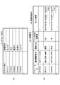
図7(A)は、オペレータDBのデータ構成例を示す図である。図7(A)において、オペレータDB31は、オペレータID、接続状況などの項目を有する。オペレータIDは、オペレータを識別すると共に、実質的にはオペレータ端末9を特定するために使用される識別情報である。接続状況には、図6で示したオペレータ端末200の状態に対応した値が設定される。即ち、接続状況には、「通話中」、「保留中」、「ロック中」、「空き」を示す値が設定される。
FIG. 7A shows an example of the data structure of the operator DB. In FIG. 7A, the operator DB 31 has items such as operator ID and connection status. The operator ID is identification information used for identifying the operator and substantially specifying the operator terminal 9. In the connection status, a value corresponding to the state of the operator terminal 200 shown in FIG. 6 is set. That is, values indicating “busy”, “holding”, “locked”, and “free” are set in the connection status.
「通話中」は、オペレータが顧客と通話している状態、つまり、オペレータ端末200が図6に示す通話中状態(ST2又はST11)であることを示している。
“During a call” indicates that the operator is in a call with a customer, that is, the operator terminal 200 is in a call state (ST2 or ST11) shown in FIG.
「保留中」は、オペレータが電話を保留している状態、つまり、オペレータ端末200が図6に示す保留中状態(ST4又はST9)であることを示している。
“On hold” indicates that the operator is holding the call, that is, the operator terminal 200 is in the hold state (ST4 or ST9) shown in FIG.
「ロック中」は、保留中状態(ST4)で顧客から電話が切れた場合、同一顧客端末9からの再接続に備えて、所定時間、他の顧客からの接続を排除している状態、つまり、オペレータ端末200が図6に示すロック中状態(ST7)であることを示している。顧客から電話が切れた際に、オペレータは、ロック時間標準値を選択しておくことで、他の顧客の電話によって割り込まれることなく、作業に集中することができる。
“Locked” is a state in which a connection from another customer is excluded for a predetermined time in preparation for reconnection from the same customer terminal 9 when a call is disconnected from the customer in the on-hold state (ST4). The operator terminal 200 is in the locked state (ST7) shown in FIG. When the telephone is disconnected from the customer, the operator can concentrate on the work without being interrupted by another customer's telephone by selecting the lock time standard value.
「空き」は、オペレータ端末200が接続可能な状態、つまり、オペレータ端末200が図6に示す空き状態(ST1、ST8、又はST10)であることを示している。
“Free” indicates that the operator terminal 200 is connectable, that is, the operator terminal 200 is in the free state (ST1, ST8, or ST10) shown in FIG.
図7(A)に示されるオペレータDB31のデータ例では、オペレータID「OP11111」の接続状況は「ロック中」であり、オペレータID「OP22222」の接続状況は「空き」であり、オペレータID「OP33333」の接続状況は「通話中」であり、オペレータID「OP44444」の接続状況は「保留中」であることが示されている。更に、オペレータID「OP55555」の接続状況が「ロック中」であることが示されている。
In the data example of the operator DB 31 shown in FIG. 7A, the connection status of the operator ID “OP11111” is “locked”, the connection status of the operator ID “OP22222” is “free”, and the operator ID “OP33333”. The connection status of “” is “busy”, and the connection status of the operator ID “OP44444” is “pending”. Furthermore, it is indicated that the connection status of the operator ID “OP55555” is “locking”.
図7(B)は、接続制御DBのデータ構成例を示す図である。図7(B)において、接続制御DB32は、オペレータID、顧客電話番号、接続方法、ロック時間標準値、ロック時間などの項目を有する。オペレータIDは、オペレータを識別するための識別情報であるが、実質的にはオペレータ端末9を特定するために使用される。顧客電話番号は、顧客端末9の電話番号を示す。接続方法とロック時間標準値とによって、接続条件32aが示される。
FIG. 7B is a diagram showing a data configuration example of the connection control DB. In FIG. 7B, the connection control DB 32 has items such as operator ID, customer telephone number, connection method, lock time standard value, and lock time. The operator ID is identification information for identifying the operator, but is substantially used to specify the operator terminal 9. The customer telephone number indicates the telephone number of the customer terminal 9. The connection condition 32a is indicated by the connection method and the lock time standard value.
接続方法には、オペレータが図16に示すような再接続条件設定画面300の接続方法選択302から選択した接続方法が設定される。オペレータが「保留」ボタン302aを選択した場合、接続方法は保留接続を示す。オペレータが「呼出」ボタン302bを選択した場合、接続方法は通常接続を示す。
The connection method selected by the operator from the connection method selection 302 on the reconnection condition setting screen 300 as shown in FIG. 16 is set as the connection method. When the operator selects the “pending” button 302a, the connection method indicates a pending connection. When the operator selects the “call” button 302b, the connection method indicates normal connection.
ロック時間標準値には、オペレータが図16に示すような再接続条件設定画面300のロック時間標準値選択301から選択したロック時間標準値が設定される。例えば、オペレータが「1分」ボタン301aを選択した場合、接続方法は「1分」を示す。
In the lock time standard value, the lock time standard value selected by the operator from the lock time standard value selection 301 on the reconnection condition setting screen 300 as shown in FIG. 16 is set. For example, when the operator selects the “1 minute” button 301a, the connection method indicates “1 minute”.
ロック時間には、オペレータDB31の接続状況を「保留中」から「ロック中」に変更するときに、ロック時間標準値に基づいて、他の顧客端末9からの接続が抑制されるロック時間が設定される。
The lock time is set so that the connection from other customer terminals 9 is suppressed based on the lock time standard value when the connection status of the operator DB 31 is changed from “pending” to “locked”. Is done.
図7(B)に示される接続制御DB32のデータ例では、オペレータDB31にてオペレータID「OP44444」に対応する接続状況が「保留中」になると、オペレータID「OP44444」に顧客電話番号「090-1111-2222」を対応させたレコードが作成される。レコードが作成された時点では、ロック時間は空欄である。
In the data example of the connection control DB 32 shown in FIG. 7B, when the connection status corresponding to the operator ID “OP44444” in the operator DB31 becomes “pending”, the customer telephone number “090-” is assigned to the operator ID “OP44444”. A record corresponding to “1111-2222” is created. At the time when the record is created, the lock time is blank.
オペレータID「OP44444」のオペレータが保留を解除すると、オペレータDB31にてオペレータID「OP44444」に対応する接続状況が「通話中」に変更され、このレコードは削除される。
When the operator with the operator ID “OP44444” releases the hold, the connection status corresponding to the operator ID “OP44444” is changed to “busy” in the operator DB 31, and this record is deleted.
又は、オペレータID「OP44444」のオペレータが、保留中に通話が切断された際に表示される図16に示すような再接続条件設定画面300から不要303を選択すると、オペレータDB31にてオペレータID「OP44444」に対応する接続状況が「空き」に変更され、このレコードは削除される。
Alternatively, when the operator with the operator ID “OP44444” selects the unnecessary 303 from the reconnection condition setting screen 300 shown in FIG. 16 displayed when the call is disconnected during the hold, the operator ID “ The connection status corresponding to “OP44444” is changed to “free”, and this record is deleted.
「保留中」となり作成された、オペレータID「OP11111」と顧客電話番号「090-3333-4444」を対応させたレコードは、顧客端末9によって呼切断されたことによってロック時間が設定された状態を示している。
The record that is created as “pending” and that corresponds to the operator ID “OP11111” and the customer telephone number “090-3333-4444” indicates that the lock time is set when the call is disconnected by the customer terminal 9. Show.
ロック時間は、「yyyy/mm/dd hh:mm:ss~hh:mm:ss」の形式によって、年月日、及びロック開始時間~ロック終了時間を示す。切断時刻がロック開始時間に設定され、オペレータが指定したロック時間標準値を切断時刻に加算した値がロック終了時間に設定される。
The lock time indicates the date and the lock start time to the lock end time in the format “yyyy / mm / dd hh: mm: ss to hh: mm: ss”. The disconnection time is set as the lock start time, and a value obtained by adding the lock time standard value designated by the operator to the disconnection time is set as the lock end time.
この例では、オペレータが指定したロック時間標準値「3分」が切断時刻に加算されることによって、「2010/09/30 10:20:55~10:23:55」が設定されている。年月日「2010/09/30」のロック開始時間「10:20:55」からロック終了時間「10:23:55」までは、オペレータID「OP11111」に対して他の顧客からの電話が接続されないように制御される。
In this example, the lock time standard value “3 minutes” specified by the operator is added to the disconnection time, thereby setting “2010/09/30 10:20:55 to 10:23:55”. From the lock start time “10:20:55” of the date “2010/09/30” to the lock end time “10:23:55”, calls from other customers are made to the operator ID “OP11111”. It is controlled not to be connected.
オペレータDB31にてオペレータID「OP11111」の接続状況は「ロック中」であり、この「ロック中」に、同一顧客電話番号「090-3333-4444」から電話があった場合、接続状況は「ロック中」から「保留中」へと変更されると共に、接続制御DB32におけるオペレータID「OP11111」のロック時間が空欄に設定される。
The connection status of the operator ID “OP11111” in the operator DB 31 is “locked”, and when a call is made from the same customer telephone number “090-3333-4444” to this “locked”, the connection status is “locked” In addition to being changed from “medium” to “pending”, the lock time of the operator ID “OP11111” in the connection control DB 32 is set to a blank.
一方、接続制御DB32におけるオペレータID「OP11111」のロック時間が経過すると、オペレータID「OP11111」のレコードは削除される。また、オペレータDB31のオペレータID「OP11111」の接続状況は「空き」に設定される。
On the other hand, when the lock time of the operator ID “OP11111” in the connection control DB 32 has elapsed, the record of the operator ID “OP11111” is deleted. Further, the connection status of the operator ID “OP11111” in the operator DB 31 is set to “free”.
同様に、「保留中」となり作成された、オペレータID「OP55555」と顧客電話番号「090-5555-6666」を対応させたレコードは、顧客端末9によって呼切断されたことによってロック時間が設定された状態を示している。
Similarly, the record corresponding to the operator ID “OP55555” and the customer telephone number “090-5555-6666” created as “pending” is set with the lock time when the call is disconnected by the customer terminal 9. Shows the state.
この例では、オペレータが指定したロック時間標準値「1分」を切断時刻に加算されることによって、「2010/09/30 10:20:50~10:21:50」が設定されている。年月日「2010/09/30」のロック開始時間「10:20:55」からロック終了時間「10:23:55」までは、オペレータID「OP11111」に対して他の顧客からの電話が接続されないように制御される。
In this example, “2010/09/30 50 10: 20: 50-10: 21: 50” is set by adding the lock time standard value “1 minute” specified by the operator to the disconnection time. From the lock start time “10:20:55” of the date “2010/09/30” to the lock end time “10:23:55”, calls from other customers are made to the operator ID “OP11111”. It is controlled not to be connected.
オペレータDB31にてオペレータID「OP11111」の接続状況は「ロック中」であり、この「ロック中」に、同一顧客電話番号「090-5555-6666」から電話があった場合、接続状況は「ロック中」から「通話中」へと変更され、このレコードは削除される。
In the operator DB 31, the connection status of the operator ID “OP11111” is “locked”. When a call is received from the same customer telephone number “090-5555-6666” in this “locked” status, the connection status is “locked”. It changes from “medium” to “busy” and this record is deleted.
次に、本実施例に係る顧客からの電話の接続制御処理について以下に説明する。先ず、サーバ100の接続制御処理部40における接続確認部41によって行われる接続確認処理について説明する。図8は、サーバの接続制御処理部における接続確認部による接続確認処理を説明するためのフローチャート図である。
Next, the telephone connection control processing from the customer according to the present embodiment will be described below. First, connection confirmation processing performed by the connection confirmation unit 41 in the connection control processing unit 40 of the server 100 will be described. FIG. 8 is a flowchart for explaining the connection confirmation processing by the connection confirmation unit in the connection control processing unit of the server.
図8において、接続確認部41は、所定時間間隔で、顧客からの呼を受信したか否かを判断する(ステップS11)。接続確認部41は顧客端末9からの接続要求(呼)を受信したか否かを判断し、接続要求を受信していない場合、接続要求の受信待ちとなり、ステップS11を繰り返す。
In FIG. 8, the connection confirmation unit 41 determines whether or not a call from a customer has been received at predetermined time intervals (step S11). The connection confirmation unit 41 determines whether or not a connection request (call) from the customer terminal 9 has been received. If no connection request has been received, the connection confirmation unit 41 waits for reception of a connection request and repeats step S11.
一方、ステップS11にて、接続要求を受信した場合、接続確認部41は、接続要求から顧客電話番号38を取得して、記憶部30に顧客電話番号38を記憶する(ステップS12)。
On the other hand, when the connection request is received in step S11, the connection confirmation unit 41 acquires the customer telephone number 38 from the connection request, and stores the customer telephone number 38 in the storage unit 30 (step S12).
そして、接続確認部41は、接続制御DB32を参照して、ロック時間が設定されている顧客電話番号38のレコードが存在するか否かを判断する(ステップS13)。顧客電話番号38のレコードが存在しない場合、接続確認部41は、通話処理部50に通常接続による通話処理を実行させ(ステップS14)、通話処理の終了によって、この接続確認処理を終了する。
Then, the connection confirmation unit 41 refers to the connection control DB 32 and determines whether there is a record of the customer telephone number 38 for which the lock time is set (step S13). When the record of the customer telephone number 38 does not exist, the connection confirmation unit 41 causes the call processing unit 50 to perform call processing by normal connection (step S14), and ends the connection confirmation processing when the call processing ends.
一方、ステップS13にて、顧客電話番号38のレコードが存在する場合、接続確認部41は、ロック中状態(ST7)で同一顧客電話番号38からの再接続であると判断し、再接続処理部60に再接続処理を実行させ(ステップS15)、再接続処理の終了によって、この接続確認処理を終了する。
On the other hand, if there is a record of the customer phone number 38 in step S13, the connection confirmation unit 41 determines that the connection is the same customer phone number 38 in the locked state (ST7), and the reconnection processing unit 60 is caused to execute the reconnection process (step S15), and the connection confirmation process is terminated when the reconnection process is completed.
図8のステップS14での通話処理部50による通常接続による通話処理について図9で説明する。図9は、図8のステップS14での通常接続による通話処理を説明するためのフローチャート図である。図9において、通話処理部50が接続制御処理部40の接続確認部41から顧客端末9からの接続要求に対する通話処理の指示を受けると、通話処理部50のオペレータ決定部51は、オペレータDB31を参照することによって、接続状況が「空き」を示すオペレータIDが存在するか否かを判断する(ステップS21)。オペレータIDが存在しない場合、オペレータ決定部51は、顧客を待ち行列に入れて(ステップS22)、接続状況が「空き」を示すオペレータIDを取得できるまでステップS21へ戻り上述同様の処理を繰り返す。
Referring to FIG. 9, the call process by the normal connection by the call processing unit 50 in step S14 of FIG. FIG. 9 is a flowchart for explaining the call processing by the normal connection in step S14 of FIG. In FIG. 9, when the call processing unit 50 receives a call processing instruction for a connection request from the customer terminal 9 from the connection confirmation unit 41 of the connection control processing unit 40, the operator determination unit 51 of the call processing unit 50 stores the operator DB 31. By referencing, it is determined whether or not there is an operator ID whose connection status indicates “free” (step S21). If the operator ID does not exist, the operator determination unit 51 puts the customer in a queue (step S22), returns to step S21 until the operator ID indicating that the connection status indicates “vacant” can be acquired, and repeats the same processing as described above.
一方、ステップS21にて、オペレータIDが存在する場合、オペレータ決定部51は、呼接続部52へオペレータDB31から取得したオペレータIDを通知する。呼接続部52は、オペレータ決定部51から通知されたオペレータIDに対応するオペレータ端末200に着信指示を送信する(ステップS23)。
On the other hand, if the operator ID is present in step S21, the operator determination unit 51 notifies the call connection unit 52 of the operator ID acquired from the operator DB 31. The call connection unit 52 transmits an incoming call instruction to the operator terminal 200 corresponding to the operator ID notified from the operator determination unit 51 (step S23).
着信指示に応じたオペレータ端末200から応答を受信すると(ステップS24)、呼接続部52は、オペレータDB31において、取得したオペレータIDの接続状況を「空き」から「通話中」に変更する(ステップS25)。
When a response is received from the operator terminal 200 according to the incoming call instruction (step S24), the call connection unit 52 changes the connection status of the acquired operator ID from “free” to “busy” in the operator DB 31 (step S25). ).
そして、通話処理部50は、接続制御処理部40の保留/解除認知部42に接続状況の変化に応じた処理を行わせ(ステップS26)、この接続確認処理を終了する。
Then, the call processing unit 50 causes the hold / release recognition unit 42 of the connection control processing unit 40 to perform processing according to the change in the connection status (Step S26), and ends this connection confirmation processing.
図8のステップS15における再接続処理部50によるロック中状態(ST7)での再接続処理について図10で説明する。図10は、図8のステップS15における保留での再接続処理を説明するためのフローチャート図である。図10において、接続制御処理部40の接続確認部41からロック中状態(ST7)での顧客端末9からの接続要求に対する再接続処理の指示を受けると、再接続処理部60の再呼接続部61は、記憶部30に格納されている顧客電話番号38を用いて接続制御DB32を参照し、オペレータIDを特定する(ステップS31)。
The reconnection processing in the locked state (ST7) by the reconnection processing unit 50 in step S15 of FIG. 8 will be described with reference to FIG. FIG. 10 is a flowchart for explaining the hold reconnection process in step S15 of FIG. In FIG. 10, when a reconnection processing instruction for the connection request from the customer terminal 9 in the locked state (ST7) is received from the connection confirmation unit 41 of the connection control processing unit 40, the reconnection connection unit of the reconnection processing unit 60 61 refers to the connection control DB 32 using the customer telephone number 38 stored in the storage unit 30 and identifies the operator ID (step S31).
再呼接続部61は、接続制御DB32において特定したオペレータIDの接続方法が保留接続を示すか否かを判断する(ステップS31-2)。
The recall connection unit 61 determines whether or not the connection method of the operator ID specified in the connection control DB 32 indicates a pending connection (step S31-2).
接続方法が保留接続を示す場合、再呼接続部61は、オペレータIDに基づくオペレータ端末200に対して、保留のままで着信する保留着信指示を送信して(ステップS32)、オペレータ端末200から保留応答を受信する(ステップS33)。
When the connection method indicates the hold connection, the recall connection unit 61 transmits a hold incoming instruction for receiving the call in the hold state to the operator terminal 200 based on the operator ID (step S32). A response is received (step S33).
オペレータ端末200から保留応答を受信すると、再呼接続部61は、オペレータDB31において、ステップS31で特定したオペレータIDの接続状況を「ロック中」から「保留中」に変更する(ステップS34)。
When receiving the hold response from the operator terminal 200, the recall connection unit 61 changes the connection status of the operator ID specified in step S31 from “locked” to “pending” in the operator DB 31 (step S34).
また、再呼接続部61は、接続制御DB32において、ステップS31で特定したオペレータIDのロック時間を空欄にする(ステップS35)。そして、再呼接続部61による再接続処理を終了し、接続制御処理部40の保留/解除認知部42による保留/解除認知処理(図11及び図12)において、保留後の接続状況の変化に応じた処理を行う。
Also, the recall connection unit 61 sets the lock time of the operator ID specified in step S31 in the connection control DB 32 to be blank (step S35). Then, the reconnection process by the recall connection unit 61 is terminated, and in the hold / release recognition process (FIGS. 11 and 12) by the hold / release recognition unit 42 of the connection control processing unit 40, the connection status after the hold is changed. Perform appropriate processing.
一方、ステップS31-2において、接続方法が通常接続を示す場合、再呼接続部61は、オペレータ端末200の呼び出し音を鳴らす(ステップS32-2)。そして、再呼接続部61は、オペレータ端末200に着信指示を送り(ステップS33-2)、オペレータ端末200から応答を受信する(ステップS34-2)。
On the other hand, when the connection method indicates normal connection in step S31-2, the recall connection unit 61 sounds the ringing tone of the operator terminal 200 (step S32-2). Then, the recall connection unit 61 sends an incoming call instruction to the operator terminal 200 (step S33-2), and receives a response from the operator terminal 200 (step S34-2).
オペレータ端末200から応答を受信した後、再呼接続部61は、オペレータDB31において、ステップS31で特定したオペレータIDの接続状況を「ロック中」から「通話中」に変更する(ステップS35-2)。
After receiving the response from the operator terminal 200, the recall connection unit 61 changes the connection status of the operator ID specified in step S31 from “locked” to “busy” in the operator DB 31 (step S35-2). .
更に、再呼接続部61は、接続制御DB32から、ステップS31で特定したオペレータIDのレコードを削除する(ステップS36-2)。そして、再呼接続部61による再接続処理を終了し、通話処理部50の通話処理(図9)のステップS26へ戻り、通話通からの接続状況の変化に応じた処理を行う。
Further, the recall connection unit 61 deletes the record of the operator ID specified in step S31 from the connection control DB 32 (step S36-2). Then, the reconnection process by the recall connection unit 61 is terminated, the process returns to step S26 of the call process (FIG. 9) of the call processing unit 50, and a process corresponding to a change in the connection status from the call communication is performed.
次に、接続制御処理部40の保留/解除認知部42による保留/解除認知処理について図11及び図12で説明する。図11及び図12は、接続制御処理部の保留/解除認知部による保留/解除認知処理を説明するためのフローチャート図である。図11及び図12において、接続制御処理部40の保留/解除認知部42は、イベント通知に応じて、保留処理、保留解除処理、又は切断処理のいずれかを行う。
Next, the hold / release recognition process by the hold / release recognition unit 42 of the connection control processing unit 40 will be described with reference to FIGS. 11 and 12 are flowcharts for explaining the hold / release recognition process by the hold / release recognition unit of the connection control processing unit. 11 and 12, the hold / release recognition unit 42 of the connection control processing unit 40 performs any of the hold process, the hold release process, or the disconnection process in response to the event notification.
保留/解除認知部42は、イベント通知によって、オペレータ端末200からの保留を認知したか否かを判断する(ステップS41)。
The hold / release recognition unit 42 determines whether or not the hold from the operator terminal 200 is recognized by the event notification (step S41).
オペレータがオペレータ端末200のディスプレイ装置231に表示される保留ボタンをポインティングデバイス232で選択すると、保留を示すイベント通知が保留/解除認知部42へ送信される。また、オペレータがオペレータ端末200のディスプレイ装置231に表示される切断ボタンをポインティングデバイス232で選択すると、通話終了による切断を示すイベント通知が保留/解除認知部42へ送信される。
When the operator selects the hold button displayed on the display device 231 of the operator terminal 200 with the pointing device 232, an event notification indicating the hold is transmitted to the hold / release recognition unit 42. When the operator selects a disconnect button displayed on the display device 231 of the operator terminal 200 with the pointing device 232, an event notification indicating disconnection due to the end of the call is transmitted to the hold / release recognition unit 42.
ステップS41において、保留を認知しなかった場合、保留/解除認知部42は、イベント通知によって、オペレータ端末200からの通話終了による切断であるか否かを判断する(ステップS41-2)。通話終了による切断でない場合、保留/解除認知部42は、ステップS41へ戻り、上述同様の処理を繰り返す。
If the hold is not recognized in step S41, the hold / release recognition unit 42 determines whether the call is disconnected due to the end of the call from the operator terminal 200 based on the event notification (step S41-2). If the call is not disconnected due to the end of the call, the hold / release recognition unit 42 returns to step S41 and repeats the same processing as described above.
一方、ステップS41-2において、通話終了による切断の場合、通話を切断し、切断したオペレータのオペレータIDをイベント通知から取得して、オペレータDB31のオペレータIDの接続状況を「通話中」から「空き」に変更して(ステップS41-4)、保留/解除認知処理を終了する。
On the other hand, in the case of disconnection due to the end of the call in step S41-2, the call is disconnected, the operator ID of the disconnected operator is obtained from the event notification, and the connection status of the operator ID in the operator DB 31 is changed from “busy” to “empty” (Step S41-4), and the hold / release recognition process is terminated.
一方、ステップS41において、保留を認知した場合、オペレータ端末200でオンフックにし、保留音を流すようにする(ステップS42)。顧客端末9へ保留音を送信する一方で、顧客端末9の音声はオペレータ端末200へ送信される。そのため、オペレータは、保留中の顧客端末9側での顧客の状況を知ることができる。
On the other hand, when the hold is recognized in step S41, the operator terminal 200 is put on-hook and the hold sound is played (step S42). While the holding sound is transmitted to the customer terminal 9, the voice of the customer terminal 9 is transmitted to the operator terminal 200. Therefore, the operator can know the situation of the customer on the customer terminal 9 side on hold.
そして、保留/解除認知部42は、オペレータDB31において、イベント通知によって示されるオペレータIDを用いて、保留したオペレータの接続状況を「通話中」から「保留中」に変更する(ステップS43)。
Then, the hold / release recognition unit 42 uses the operator ID indicated by the event notification in the operator DB 31 to change the connection status of the held operator from “busy” to “hold” (step S43).
また、保留/解除認知部42は、接続制御DB32に新規レコードを作成し、オペレータIDと顧客電話番号とを記録する(ステップS44)。例えば、図7(B)に示される接続制御DB32のデータ例において、オペレータID「OP44444」のレコードが、新規に作成される。
Further, the hold / release recognition unit 42 creates a new record in the connection control DB 32 and records the operator ID and the customer telephone number (step S44). For example, in the data example of the connection control DB 32 shown in FIG. 7B, a record with an operator ID “OP44444” is newly created.
保留/解除認知部42は、イベント通知によって、保留解除を認知したか否かを判断する(ステップS45)。保留解除を認知しなかった場合、次のイベント通知について同様の判断を行う。一方、保留解除を認知した場合、保留/解除認知部42は、オペレータDB31において、イベント通知によって示されるオペレータIDを用いて、保留解除したオペレータの接続状況を「保留中」から「通話中」に変更する(ステップS46)。
The hold / release recognition unit 42 determines whether or not hold release is recognized by the event notification (step S45). If the hold release is not recognized, the same determination is made for the next event notification. On the other hand, when the hold release is recognized, the hold / release recognition unit 42 uses the operator ID indicated by the event notification in the operator DB 31 to change the connection status of the released operator from “pending” to “busy”. Change (step S46).
また、保留/解除認知部42は、接続制御DB32から保留解除したオペレータのレコードを削除する(ステップS47)。例えば、図7(B)に示される接続制御DB32のデータ例において、オペレータID「OP44444」のオペレータが保留を解除した場合、
オペレータID「OP44444」のレコードが削除される。 Further, the hold /release recognition unit 42 deletes the record of the operator who released the hold from the connection control DB 32 (step S47). For example, in the data example of the connection control DB 32 shown in FIG. 7B, when the operator with the operator ID “OP44444” releases the hold,
The record with the operator ID “OP44444” is deleted.
オペレータID「OP44444」のレコードが削除される。 Further, the hold /
The record with the operator ID “OP44444” is deleted.
また、保留/解除認知部42は、イベント通知によって、通話終了による切断であるか否かを判断する(ステップS48)。通話終了による切断でない場合、次のイベント通知について同様の判断を行う。一方、通話終了による切断の場合、通話を切断し、切断したオペレータのオペレータIDをイベント通知から取得して、オペレータDB31のオペレータIDの接続状況を「通話中」から「空き」に変更して(ステップS49)、保留/解除認知処理を終了する。
Further, the hold / release recognition unit 42 determines whether or not the call is disconnected due to the end of the call based on the event notification (step S48). If the call is not disconnected due to the end of the call, the same determination is made for the next event notification. On the other hand, in the case of disconnection due to the end of the call, the call is disconnected, the operator ID of the disconnected operator is obtained from the event notification, and the connection status of the operator ID in the operator DB 31 is changed from “busy” to “empty” ( Step S49), the hold / release recognition process is terminated.
また、保留/解除認知部42は、通話処理部50からのイベント通知によって、切断を認知したか否かを判断する(ステップS50)。切断を認知しなかった場合、保留/解除認知部42は、保留/解除認知処理を終了する。一方、切断を認知した場合、保留/解除認知部42は、ロック設定部43にロック設定処理を行わせ(ステップS51)、保留/解除認知処理を終了する。
Further, the hold / release recognition unit 42 determines whether or not the disconnection is recognized by the event notification from the call processing unit 50 (step S50). If the disconnection is not recognized, the hold / release recognition unit 42 ends the hold / release recognition process. On the other hand, when recognizing the disconnection, the hold / release recognition unit 42 causes the lock setting unit 43 to perform the lock setting process (step S51), and ends the hold / release recognition process.
上述した保留/解除認知処理において、ステップS43及びS44が図6の保留中(ST47)に相当し、ステップS41-3が図6の空き状態(ST3)に相当する。また、ステップS46及びS47が図6の通話中状態(ST5)に相当し、ステップS49が図6の空き状態(ST6)に相当する。
In the hold / release recognition process described above, steps S43 and S44 correspond to the hold state (ST47) in FIG. 6, and step S41-3 corresponds to the empty state (ST3) in FIG. Further, steps S46 and S47 correspond to the busy state (ST5) in FIG. 6, and step S49 corresponds to the idle state (ST6) in FIG.
図13は、図12のステップS51でのロック設定処理について説明するフローチャート図である。図13において、ロック設定部43は、オペレータ端末9のディスプレイ装置231に再接続条件設定画面300を表示させる(ステップS511)。
FIG. 13 is a flowchart for explaining the lock setting process in step S51 of FIG. In FIG. 13, the lock setting unit 43 displays the reconnection condition setting screen 300 on the display device 231 of the operator terminal 9 (step S511).
ロック設定部43は、オペレータ端末9のオペレータから取得した接続条件がロックを必要とすることを示しているか否かを判断する(ステップS512)。オペレータが図16に示すような再接続条件設定画面300からロック時間標準値選択301と接続方法選択302とを選択した場合、接続条件にロック時間標準値と接続方法とが含まれることによって、ロックが必要であると判断する。ロックが必要であると判断した場合、ロック設定部43は、オペレータが指定したロック時間標準値と接続方法とを取得して、記憶部30の作業領域にロック時間標準値と接続方法を示す接続条件情報39を格納する(ステップS513)。
The lock setting unit 43 determines whether or not the connection condition acquired from the operator of the operator terminal 9 indicates that the lock is required (step S512). When the operator selects the lock time standard value selection 301 and the connection method selection 302 from the reconnection condition setting screen 300 as shown in FIG. 16, the lock condition standard value and the connection method are included in the connection conditions. Is determined to be necessary. When it is determined that the lock is necessary, the lock setting unit 43 acquires the lock time standard value and the connection method designated by the operator, and the connection indicating the lock time standard value and the connection method in the work area of the storage unit 30. The condition information 39 is stored (step S513).
ロック設定部43は、オペレータDB31において、ロックしたオペレータの接続状況を保留中から「保留中」から「ロック中」に変更する(ステップS514)。
The lock setting unit 43 changes the connection status of the locked operator from “suspended” to “locked” in the operator DB 31 (step S514).
ロック設定部43は、接続制御DBのロックしたオペレータのレコードにおいて、記憶部30の作業領域に格納した接続方法を記録し、切断時刻に記憶部30の作業領域に格納したロック時間標準値を加算したロック時間を記録して(ステップS515)、ロック設定処理を終了する。
The lock setting unit 43 records the connection method stored in the work area of the storage unit 30 in the record of the locked operator in the connection control DB, and adds the lock time standard value stored in the work area of the storage unit 30 to the disconnection time. The locked time is recorded (step S515), and the lock setting process is terminated.
一方、ステップS512において、オペレータが再接続条件設定画面300から不要303を選択したと判断した場合、ロック設定部43は、通話を切断し、オペレータDB31において、オペレータの接続状況を「保留中」から「空き」に変更する(ステップS516)。また、ロック設定部43は、接続制御DB32からロック不要にしたオペレータのレコードを削除して(ステップS517)、ロック設定処理を終了する。
On the other hand, when it is determined in step S512 that the operator has selected unnecessary 303 from the reconnection condition setting screen 300, the lock setting unit 43 disconnects the call, and the operator DB31 changes the connection status of the operator from “pending”. “Free” is changed (step S516). Further, the lock setting unit 43 deletes the record of the operator who made the lock unnecessary from the connection control DB 32 (step S517), and ends the lock setting process.
上述したロック設定処理において、ステップS514及びS515が図6のロック中(ST7)に相当し、ステップS516及びS517が図6の空き状態(ST10)に相当する。
In the lock setting process described above, steps S514 and S515 correspond to the locked state (ST7) in FIG. 6, and steps S516 and S517 correspond to the empty state (ST10) in FIG.
次に、接続制御処理部40のロック管理部44によるロック管理処理について図16で説明する。図14は、接続制御処理部のロック管理部によるロック管理処理を説明するためのフローチャート図である。図14において、ロック管理部44は、ステップS81からS83までの処理を繰り返して実行する。
Next, lock management processing by the lock management unit 44 of the connection control processing unit 40 will be described with reference to FIG. FIG. 14 is a flowchart for explaining lock management processing by the lock management unit of the connection control processing unit. In FIG. 14, the lock management unit 44 repeatedly executes the processing from steps S81 to S83.
ロック管理部44は、接続制御DB32においてロック時間を経過したレコードが存在するか否かを判断する(ステップS81)。ロック時間を経過したレコードが存在しない場合、このステップS81へ戻る。
The lock management unit 44 determines whether there is a record whose lock time has elapsed in the connection control DB 32 (step S81). If there is no record whose lock time has passed, the process returns to step S81.
ロック時間を経過したレコードが存在する場合、ロック管理部44は、そのレコードからオペレータIDを取得した後、接続制御DB32から当該レコードを削除する(ステップS82)。そして、ロック管理部44は、オペレータDB31において、ステップS82で取得したオペレータIDに対応付けた接続状況を「ロック中」から「空き」に変更して(ステップS83)、ステップS81へ戻り、上述同様の処理を繰り返す。
If there is a record whose lock time has elapsed, the lock management unit 44 acquires the operator ID from the record, and then deletes the record from the connection control DB 32 (step S82). Then, the lock management unit 44 changes the connection status associated with the operator ID acquired in step S82 from “locked” to “empty” in the operator DB 31 (step S83), returns to step S81, and the same as described above. Repeat the process.
上述したロック管理処理において、ステップS28が図6の空き状態(ST8)に相当する。
In the lock management process described above, step S28 corresponds to the empty state (ST8) in FIG.
次に、オペレータ端末200側での呼通信処理を図15で説明する。図15は、オペレータ端末の呼通信部での呼通信処理を説明するための図である。図15において、呼通信部71は、サーバ100からのパケット受信又はオペレータの操作によるイベントを検出する毎に、ステップS101からS120を繰り返す。
Next, call communication processing on the operator terminal 200 side will be described with reference to FIG. FIG. 15 is a diagram for explaining call communication processing in the call communication unit of the operator terminal. In FIG. 15, the call communication unit 71 repeats steps S101 to S120 every time it detects an event due to reception of a packet from the server 100 or an operator's operation.
オペレータ端末200において、呼通信部71は、検出イベントが着信したことを示すか否かを判断する(ステップS101)。検出イベントが着信したことを示さない場合、呼通信部71は、ステップS103へ進む。検出イベントが着信したことを示す場合、呼通信部71は着信を音声出力処理部75に通知することによって、呼び出し音が再生されてスピーカー235から出力される(ステップS102)。
In operator terminal 200, call communication unit 71 determines whether or not the detection event indicates that it has arrived (step S101). If the detection event does not indicate that the incoming call has arrived, the call communication unit 71 proceeds to step S103. When the detected event indicates that the incoming call has arrived, the call communication unit 71 notifies the voice output processing unit 75 of the incoming call, whereby the ringing tone is reproduced and output from the speaker 235 (step S102).
呼通信部71は、検出イベントが保留着信したことを示すか否かを判断する(ステップS103)。検出イベントが保留着信したことを示さない場合、呼通信部71は、ステップS107へ進む。ここで、保留着信とは、ロック中状態(ST7)(図6)で顧客端末9から再接続要求を受けたことを言う。
The call communicator 71 determines whether or not the detected event indicates that the call has been put on hold (step S103). If the detected event does not indicate that the call has been put on hold, the call communication unit 71 proceeds to step S107. Here, the pending incoming call means that a reconnection request is received from the customer terminal 9 in the locked state (ST7) (FIG. 6).
検出イベントが保留着信したことを示す場合、呼通信部71は、呼び出し音の再生を行うことなく、保留応答信号をサーバ100へ送信し(ステップS104)、更に、補助記憶装置217に予め格納しておいた音声データによる保有メッセージをサーバ100を介して顧客端末9に送信する(ステップS105)。また、呼通信部71は、音声出力処理部75によって顧客端末9から受信した受信音声パケット(顧客音声)を再生させスピーカー235から出力させる(ステップS106)。
When the detected event indicates that the incoming call is on hold, the call communication unit 71 transmits a hold response signal to the server 100 without reproducing the ringing tone (step S104), and further stores it in the auxiliary storage device 217 in advance. The stored message based on the voice data is transmitted to the customer terminal 9 via the server 100 (step S105). Further, the call communication unit 71 reproduces the received voice packet (customer voice) received from the customer terminal 9 by the voice output processing unit 75 and outputs it from the speaker 235 (step S106).
本実施例では、呼通信部71は、顧客端末9に送信している保有メッセージをスピーカー235へ出力させず、顧客端末9から受信した受信音声パケットをスピーカー235から出力するように制御する。このように制御することによって、保留中の作業を継続しつつ、顧客の様子をスピーカー235から出力される顧客音声から判断することができる。
In the present embodiment, the call communication unit 71 controls the speaker 235 to output the received voice packet received from the customer terminal 9 without outputting the retained message transmitted to the customer terminal 9 to the speaker 235. By controlling in this way, the state of the customer can be determined from the customer voice output from the speaker 235 while continuing the pending work.
上述したステップS105にて顧客端末9へ送信される保留メッセージは、例えば、図17のように、顧客端末9のスピーカー253から「現在、引き続き、お調べ致しております。もうしばらく、お待ちください。」とメッセージが出力される。
The hold message transmitted to the customer terminal 9 in the above-described step S105 is, for example, as shown in FIG. 17, “Currently continuing to investigate. Please wait for a while. Message is output.
呼通信部71は、検出イベントがオペレータが応答したことを示す否かを判断する(ステップS107)。検出イベントがオペレータが応答したことを示さない場合、ステップS111へ進む。
The call communication unit 71 determines whether or not the detection event indicates that the operator has responded (step S107). If the detection event does not indicate that the operator has responded, the process proceeds to step S111.
一方、ステップS107にて、検出イベントがオペレータが応答したことを示す場合、呼通信部71は、応答信号をサーバ100へ送信し(ステップS108)、マイク234へ入力されたオペレータの音声を音声入力処理部76によって音声パケットに加工して、サーバ100を介して顧客端末9へ送信開始する(ステップS109)。また、呼通信部71は、音声出力処理部75によって顧客端末9から受信した受信音声パケット(顧客音声)を再生させスピーカー235から出力させる(ステップS110)。
On the other hand, when the detected event indicates that the operator has responded in step S107, the call communication unit 71 transmits a response signal to the server 100 (step S108), and the operator's voice input to the microphone 234 is input as voice. The processing unit 76 processes the voice packet and starts transmission to the customer terminal 9 via the server 100 (step S109). Further, the call communication unit 71 reproduces the received voice packet (customer voice) received from the customer terminal 9 by the voice output processing unit 75 and outputs it from the speaker 235 (step S110).
呼通信部71は、検出イベントがオペレータが通話を保留したことを示すか否かを判断する(ステップS111)。検出イベントがオペレータが通話を保留したことを示さない場合、呼通信部71は、ステップS114へと進む。一方、検出イベントがオペレータが通話を保留したことを示す場合、呼通信部71は、保留信号をサーバ100へ送信し(ステップS112)、保留音をサーバ100を介して顧客端末9へ送信開始する(ステップS113)。
The call communication unit 71 determines whether or not the detection event indicates that the operator has suspended the call (step S111). If the detection event does not indicate that the operator has suspended the call, the call communication unit 71 proceeds to step S114. On the other hand, when the detected event indicates that the operator has suspended the call, the call communication unit 71 transmits a hold signal to the server 100 (step S112), and starts transmitting a hold sound to the customer terminal 9 via the server 100. (Step S113).
呼通信部71は、検出イベントが保留解除を示すか否かを判断する(ステップS114)。検出イベントが保留解除を示さない場合、呼通信部71は、ステップS117へと進む。一方、検出イベントが保留解除を示す場合、呼通信部71は、保留解除信号をサーバ100へ送信し(ステップS115)、マイク234へ入力されたオペレータの音声を音声入力処理部76によって音声パケットに加工して、サーバ100を介して顧客端末9へ送信開始する(ステップS116)。
The call communication unit 71 determines whether or not the detection event indicates release of hold (step S114). If the detection event does not indicate release of hold, the call communication unit 71 proceeds to step S117. On the other hand, when the detected event indicates release of hold, the call communication unit 71 transmits a hold release signal to the server 100 (step S115), and the voice of the operator input to the microphone 234 is converted into a voice packet by the voice input processing unit 76. Processing is started and transmission to the customer terminal 9 is started via the server 100 (step S116).
呼通信部71は、検出イベントがオペレータによって切断されたことを示すか否かを判断する(ステップS117)。検出イベントがオペレータによって切断されたことを示さない場合、呼通信部71は、マイク234へ入力されたオペレータの音声の送信を停止し(ステップS118)、顧客端末9から受信した受信音声パケット(顧客音声)の再生を停止して(ステップS119)、切断信号をサーバ100へ送信する(ステップS120)。そして、呼通信部71は、呼通信処理を終了する。
The call communication unit 71 determines whether or not the detection event indicates that the operator has disconnected (step S117). If the detected event does not indicate that the operator has disconnected, the call communication unit 71 stops transmitting the operator's voice input to the microphone 234 (step S118), and receives the received voice packet (customer) from the customer terminal 9 (Sound) reproduction is stopped (step S119), and a disconnection signal is transmitted to the server 100 (step S120). Then, the call communication unit 71 ends the call communication process.
上述したように、本実施例では、保留されるとオペレータ端末200がオンフックとなるため、オペレータは、オペレータ端末200から送出される顧客音声によって、保留中の顧客の状況を把握することができる。また、保留中の切断を契機に、図16に示すような再接続条件設定画面300がオペレータ端末200に表示されることによって、オペレータは、回線が切断されたことを視覚的に確認できる。
As described above, in this embodiment, since the operator terminal 200 becomes on-hook when it is put on hold, the operator can grasp the status of the customer on hold by the customer voice transmitted from the operator terminal 200. Further, when the reconnection condition setting screen 300 as shown in FIG. 16 is displayed on the operator terminal 200 in response to the pending disconnection, the operator can visually confirm that the line has been disconnected.
オペレータが設定した保留中に切断された場合、オペレータが、図16に示すような再接続条件設定画面300から同一顧客端末9からの再接続要求を受けるためにオペレータ端末200の回線をロックするか否かを選択することができる。
Whether the operator locks the line of the operator terminal 200 in order to receive a reconnection request from the same customer terminal 9 from the reconnection condition setting screen 300 as shown in FIG. You can choose whether or not.
また、ロックを選択した場合、オペレータは、同一顧客端末9からの再接続要求(ロック中再接続)でオペレータの着呼応答操作の必要のない保留状態のままで回線接続させるか、或いは、通常接続と同様に呼び出し音により応答して顧客と会話をするかを選択できる。
When the lock is selected, the operator can connect the line in the hold state without the need for the operator's call response operation by the reconnection request (reconnection during lock) from the same customer terminal 9, or normally As with connection, it is possible to select whether to respond with a ringing tone and talk with the customer.
従って、オペレータは、保留中に切断された状況を考慮した顧客への対応を選択することができる。
Therefore, the operator can select the response to the customer in consideration of the situation of being disconnected while on hold.
ロック中再接続に応じて保留状態のままで回線接続することを選択した場合、コールセンタのオペレータは、顧客の問合せに対する回答を調査するため顧客端末9の顧客との通話を保留にした後、回線切断により顧客端末9から再接続要求があった場合に、着呼応答操作をすることなく、調査作業に集中することができる。従って、オペレータは、結果的に実質的な応答作業を迅速化することが可能となる。
If the call center operator selects to connect the line in the hold state in response to the reconnection in the locked state, the call center operator puts the call with the customer on the customer terminal 9 in order to investigate the answer to the customer inquiry, When there is a reconnection request from the customer terminal 9 due to disconnection, it is possible to concentrate on the investigation work without performing an incoming call response operation. Therefore, the operator can speed up the substantial response work as a result.
更に、オペレータは、オペレータ端末200から送出される顧客音声から電話が切れた状況を判断して、再接続条件設定画面300からロック時間を設定できるため、電波状況が悪いため電話が切れた顧客に対しては、ロック時間を長めの「5分」を指定する。また、保留中に一方的に電話を切った顧客に対しては、ロック時間を短めの「1分」を指定したり、或いは、ロック不要にして、他の新たな顧客の電話を受けるようにすることができる。
Furthermore, the operator can determine the situation where the call is disconnected from the customer voice transmitted from the operator terminal 200, and can set the lock time from the reconnection condition setting screen 300. On the other hand, “5 minutes” with a longer lock time is designated. Also, for customers who unilaterally hang up the phone while on hold, specify “1 minute” with a shorter lock time, or make it unnecessary to lock and receive calls from other new customers. can do.
ロック中再接続に応じて呼び出して、オペレータが応答操作することによって接続することを選択した場合、オペレータは、保留中に切断された顧客の状況を考慮した会話を行い、適切な対応をすることができる。例えば、保留状態が長く、顧客が待ちきれなくて切断した場合には、オペレータは、再接続された際に、作業状況の説明などを顧客に行うことができる。
When calling in response to reconnection while locked and the operator chooses to connect by responding, the operator shall have a conversation taking into account the situation of the customer who was disconnected while on hold and take appropriate action Can do. For example, if the customer has been on hold for a long time and the customer has been unable to wait and is disconnected, the operator can explain the work status to the customer when reconnected.
本発明は、具体的に開示された実施例に限定されるものではなく、特許請求の範囲から逸脱することなく、種々の変形や変更が可能である。
The present invention is not limited to the specifically disclosed embodiments, and various modifications and changes can be made without departing from the scope of the claims.
5 公衆回線網
6 ネットワーク
6a 空き状態
6b 通話中状態
6c 保留中状態
6d ロック中状態
6e オペレータ保留状態
9 顧客端末
11 CPU
12 メモリユニット
13 表示ユニット
14 出力ユニット
15 入力ユニット
16 通信ユニット
16a 局終端装置
16b ネットワーク通信部
17 記憶装置
18 ドライバ
19 記憶媒体
30 記憶部
31 オペレータDB
32 接続制御DB
40 接続制御部
41 接続確認部
42 保留/解除認知部
44 ロック管理部
50 通話処理部
51 オペレータ決定部
52 呼接続部
60 再接続処理部
61 再呼接続部
70 オペレータ用処理部
71 呼通信部
73 表示処理部
74 入力処理部
75 音声出力処理部
76 音声入力処理部
100 サーバ
200 オペレータ端末
210 本体
211 CPU
212 主記憶装置
213 画像処理装置
214 I/O処理装置
215 音声処理装置
216 ネットワークカード
231 ディスプレイ装置
232 ポインティングデバイス
233 キーボード
234 マイク
235 スピーカー 5 Public network 6 Network 6a Empty state 6b Calling state 6c Holding state 6d Locking state 6eOperator holding state 9 Customer terminal 11 CPU
DESCRIPTION OFSYMBOLS 12 Memory unit 13 Display unit 14 Output unit 15 Input unit 16 Communication unit 16a Station termination device 16b Network communication part 17 Storage device 18 Driver 19 Storage medium 30 Storage part 31 Operator DB
32 Connection control DB
DESCRIPTION OFSYMBOLS 40 Connection control part 41 Connection confirmation part 42 Hold / release recognition part 44 Lock management part 50 Call processing part 51 Operator determination part 52 Call connection part 60 Reconnection process part 61 Recall connection part 70 Operator process part 71 Call communication part 73 Display processing unit 74 Input processing unit 75 Audio output processing unit 76 Audio input processing unit 100 Server 200 Operator terminal 210 Main body 211 CPU
212Main storage device 213 Image processing device 214 I / O processing device 215 Audio processing device 216 Network card 231 Display device 232 Pointing device 233 Keyboard 234 Microphone 235 Speaker
6 ネットワーク
6a 空き状態
6b 通話中状態
6c 保留中状態
6d ロック中状態
6e オペレータ保留状態
9 顧客端末
11 CPU
12 メモリユニット
13 表示ユニット
14 出力ユニット
15 入力ユニット
16 通信ユニット
16a 局終端装置
16b ネットワーク通信部
17 記憶装置
18 ドライバ
19 記憶媒体
30 記憶部
31 オペレータDB
32 接続制御DB
40 接続制御部
41 接続確認部
42 保留/解除認知部
44 ロック管理部
50 通話処理部
51 オペレータ決定部
52 呼接続部
60 再接続処理部
61 再呼接続部
70 オペレータ用処理部
71 呼通信部
73 表示処理部
74 入力処理部
75 音声出力処理部
76 音声入力処理部
100 サーバ
200 オペレータ端末
210 本体
211 CPU
212 主記憶装置
213 画像処理装置
214 I/O処理装置
215 音声処理装置
216 ネットワークカード
231 ディスプレイ装置
232 ポインティングデバイス
233 キーボード
234 マイク
235 スピーカー 5 Public network 6 Network 6a Empty state 6b Calling state 6c Holding state 6d Locking state 6e
DESCRIPTION OF
32 Connection control DB
DESCRIPTION OF
212
Claims (9)
- 回線の保留及び該保留の解除を管理するための接続制御データベースを格納する記憶部と、
前記保留を認知すると、前記回線を保留した保留者の保留者端末をオンフックにして該回線が保留された被保留者の音声を該保留者端末に送出するようにして、前記接続制御データベースに、該保留者を識別する保留者識別情報と、該被保留者を識別する被保留者識別情報とを対応付けて記録する保留/解除認知部と、
前記保留/解除認知部によって保留された前記回線の切断が認知されると、該回線を切断された前記保留者識別情報に基づく前記保留者から、保留中の切断後になされた同一被保留者による再接続要求を前記保留者端末が着信するために回線をロックする接続条件を取得して、該保留者識別情報に対応付けて前記接続制御データベースに格納するロック設定部と、
前記同一被保留者による再接続要求に応じて、前記記憶部に格納された前記接続制御データベースを参照し、該再接続要求に指定される前記被保留者識別情報に対応付けられた前記接続条件に従って、該被保留者識別情報に対応付けられた前記保留者識別情報に基づいて、前記保留者端末に着信させる接続制御部と、
を有することを特徴とする回線接続装置。 A storage unit for storing a connection control database for managing line hold and release of the hold;
Recognizing the hold, on-hook the holder terminal of the holder who has held the line, and send the voice of the holdee with the line held to the holder terminal, to the connection control database, A hold / release recognition unit that records the holdee identification information for identifying the holdee and the holdee identification information for identifying the holdee in association with each other;
When disconnection of the line held by the hold / release recognition unit is recognized, from the holder based on the holder identification information that has disconnected the line, the same holdee made after disconnection on hold A lock setting unit that acquires a connection condition for locking a line so that the hold terminal receives a reconnection request, and stores it in the connection control database in association with the hold identification information;
In response to a reconnection request by the same holdee, the connection condition associated with the holdee identification information specified in the reconnection request with reference to the connection control database stored in the storage unit And a connection control unit that causes the holder terminal to receive a call based on the holder identification information associated with the holder identification information,
A circuit connection device comprising: - 前記ロック設定部は、
前記接続条件によってロックが必要であることを示しているか否かを判断するロック判断部と、
前記ロック判断部によってロックを必要とすると判断した場合、前記接続制御データベースの前記保留者識別情報に対応させて、前記保留者から取得した前記接続条件で指定される接続方法と、切断時刻に該接続条件で指定されるロック時間標準値を加算したロック時間とを設定することを特徴とする請求項1記載の回線接続装置。 The lock setting unit
A lock determination unit that determines whether the connection condition indicates that a lock is necessary;
When the lock determination unit determines that the lock is necessary, the connection method specified by the connection condition acquired from the holder corresponding to the holder identification information in the connection control database, and the disconnection time 2. The line connection apparatus according to claim 1, wherein a lock time obtained by adding a lock time standard value specified by a connection condition is set. - 前記ロック設定部は、
前記ロック判断部によってロックを不要とすると判断した場合、前記接続制御データベースから前記保留者識別情報のレコードを削除する請求項2記載の回線接続装置。 The lock setting unit
3. The line connection device according to claim 2, wherein when the lock determination unit determines that the lock is unnecessary, the record of the holdee identification information is deleted from the connection control database. - 前記接続方法は、前記保留者端末が保留で着信することを示す保留接続、又は、前記保留者端末の呼び出し音に応じて前記保留者が応答して着信することを示す通常接続を指定し、
前記制御部からの再接続の指示に応じて、前記被保留者識別情報を用いて前記接続制御データベースを参照して特定した前記保留者識別情報に対応づけられる前記接続方法を取得し、該接続方法が保留接続を指定する場合、保留状態で前記保留者の保留者端末に着信させ、前記被保留者識別情報に対応付けられる前記ロック時間を空欄にする再接続部を更に有することを特徴とする請求項2又は3記載の回線接続装置。 The connection method designates a hold connection indicating that the holder terminal receives an incoming call on hold, or a normal connection indicating that the holder responds and receives an incoming call according to a ringing sound of the holder terminal,
In response to a reconnection instruction from the control unit, the connection method associated with the holdee identification information specified by referring to the connection control database using the holdee identification information is acquired, and the connection When the method designates a hold connection, the method further includes a reconnection unit that causes the holdee terminal of the holdee to receive a call in a hold state and sets the lock time associated with the holdee identification information to be blank. The line connection device according to claim 2 or 3. - 前記再接続部は、前記接続方法が通常接続を指定する場合、前記保留者の保留者端末の呼出音により該保留者に応答させることによって着信させ、前記接続制御データベースから前記保留者識別情報のレコードを削除することを特徴とする請求項4記載の回線接続装置。 When the connection method designates normal connection, the reconnection unit is caused to receive an incoming call by responding to the holder with a ringing tone of the holder terminal of the holder, and from the connection control database, 5. The line connection apparatus according to claim 4, wherein the record is deleted.
- 前記回線接続装置はコールセンタに設置され、前記保留者識別情報はオペレータを識別する識別情報を示し、前記被保留者識別情報は前記保留者端末の電話番号を示し、
前記記憶部は、前記オペレータの前記識別情報毎に回線の接続状況を対応させて管理するオペレータデータベースを更に格納し、
前記接続状況は、前記保留/解除認知部によって、保留が認知されると保留中に設定され、保留解除が認知されると通話中に設定され、
前記接続状況は、前記ロック設定部によって、前記接続方法が保留接続を指定する場合にはロック中に設定され、該接続方法が通常接続を指定する場合には空きに設定されることを特徴とする請求項5記載の回線接続装置。 The line connection device is installed in a call center, the holdee identification information indicates identification information for identifying an operator, the holdee identification information indicates a telephone number of the holdee terminal,
The storage unit further stores an operator database that manages the connection status of the line corresponding to each identification information of the operator,
The connection status is set to hold when holding is recognized by the hold / release recognition unit, and is set to call when hold release is recognized,
The connection status is set by the lock setting unit to be locked when the connection method specifies a pending connection, and is set to be empty when the connection method specifies a normal connection. The line connection device according to claim 5. - 前記接続制御データベースから前記ロック時間を経過したレコードを削除するロック管理部を更に有することを特徴とする請求項2乃至6のいずれか一項記載の回線接続装置。 The line connection device according to any one of claims 2 to 6, further comprising a lock management unit that deletes a record that has passed the lock time from the connection control database.
- コンピュータによって実行される回線接続方法であって、該コンピュータが、
接続された回線の保留を認知すると、前記回線を保留した保留者の保留者端末をオンフックにして該回線が保留された被保留者の音声を該保留者端末に送出するようにすると共に、記憶部に格納された前記回線の保留及び該保留の解除を管理するための接続制御データベースに、該保留者を識別する保留者識別情報と、該被保留者を識別する被保留者識別情報とを対応付けて記録し、
保留された前記回線の切断が認知されると、該回線を切断された前記保留者識別情報に基づく前記保留者から、保留中の切断後になされた同一被保留者による再接続要求を前記保留者端末が着信するために回線のロックに係る接続条件を取得して、該保留者識別情報に対応付けて前記接続制御データベースに格納し、
前記同一被保留者による再接続要求に応じて、前記記憶部に格納された前記接続制御データベースを参照し、該再接続要求に指定される前記被保留者識別情報に対応付けられた接続条件に従って、該被保留者識別情報に対応付けられた前記保留者識別情報に基づいて、前記保留者端末に着信させる
ことを特徴とする回線接続方法。 A line connection method executed by a computer, the computer comprising:
When recognizing the hold of the connected line, the holder terminal of the holder holding the line is put on hook, and the voice of the holdee holding the line is sent to the holder terminal and stored. The connection control database for managing the hold of the line and the release of the hold stored in the section includes a holder identification information for identifying the holdee and a holdee identification information for identifying the holdee Record in association,
When disconnection of the held line is recognized, a request for reconnection by the same holdee made after the pending disconnection is issued from the holder based on the identification information of the holdee who has disconnected the line. Obtaining a connection condition relating to the lock of the line for the terminal to receive, and storing it in the connection control database in association with the holder identification information;
In response to a reconnection request by the same holdee, referring to the connection control database stored in the storage unit, according to a connection condition associated with the holdee identification information specified in the reconnection request A line connection method for causing a call to the holdee terminal based on the holdee identification information associated with the holdee identification information. - 接続された回線の保留を認知すると、前記回線を保留した保留者の保留者端末をオンフックにして該回線が保留された被保留者の音声を該保留者端末に送出するようにすると共に、記憶部に格納された前記回線の保留及び該保留の解除を管理するための接続制御データベースに、該保留者を識別する保留者識別情報と、該被保留者を識別する被保留者識別情報とを対応付けて記録し、
保留された前記回線の切断が認知されると、該回線を切断された前記保留者識別情報に基づく前記保留者から、保留中の切断後になされた同一被保留者による再接続要求を前記保留者端末が着信するために回線のロックに係る接続条件を取得して、該保留者識別情報に対応付けて前記接続制御データベースに格納し、
前記同一被保留者による再接続要求に応じて、前記記憶部に格納された前記接続制御データベースを参照し、該再接続要求に指定される前記被保留者識別情報に対応付けられた接続条件に従って、該被保留者識別情報に対応付けられた前記保留者識別情報に基づいて、前記保留者端末に着信させる
処理をコンピュータに実行させるプログラム。 When recognizing the hold of the connected line, the holder terminal of the holder holding the line is put on hook, and the voice of the holdee holding the line is sent to the holder terminal and stored. The connection control database for managing the hold of the line and the release of the hold stored in the section includes a holder identification information for identifying the holdee and a holdee identification information for identifying the holdee Record in association,
When disconnection of the held line is recognized, a request for reconnection by the same holdee made after the pending disconnection is issued from the holder based on the holder identification information from which the line has been disconnected. Obtaining a connection condition relating to the lock of the line for the terminal to receive, and storing it in the connection control database in association with the holder identification information;
In response to the reconnection request by the same holdee, referring to the connection control database stored in the storage unit, according to the connection condition associated with the holdee identification information specified in the reconnection request A program for causing a computer to execute a process for making an incoming call to the holder terminal based on the holder identification information associated with the holder identification information.
Priority Applications (4)
| Application Number | Priority Date | Filing Date | Title |
|---|---|---|---|
| CN201180069326.4A CN103430521B (en) | 2011-03-17 | 2011-03-17 | Connecting device for line, line connecting method |
| PCT/JP2011/056464 WO2012124122A1 (en) | 2011-03-17 | 2011-03-17 | Line connection device, line connection method, and program |
| JP2013504496A JP5621911B2 (en) | 2011-03-17 | 2011-03-17 | Line connection apparatus, line connection method, and program |
| US14/021,411 US9654947B2 (en) | 2011-03-17 | 2013-09-09 | Line connection apparatus and method |
Applications Claiming Priority (1)
| Application Number | Priority Date | Filing Date | Title |
|---|---|---|---|
| PCT/JP2011/056464 WO2012124122A1 (en) | 2011-03-17 | 2011-03-17 | Line connection device, line connection method, and program |
Related Child Applications (1)
| Application Number | Title | Priority Date | Filing Date |
|---|---|---|---|
| US14/021,411 Continuation US9654947B2 (en) | 2011-03-17 | 2013-09-09 | Line connection apparatus and method |
Publications (1)
| Publication Number | Publication Date |
|---|---|
| WO2012124122A1 true WO2012124122A1 (en) | 2012-09-20 |
Family
ID=46830249
Family Applications (1)
| Application Number | Title | Priority Date | Filing Date |
|---|---|---|---|
| PCT/JP2011/056464 WO2012124122A1 (en) | 2011-03-17 | 2011-03-17 | Line connection device, line connection method, and program |
Country Status (4)
| Country | Link |
|---|---|
| US (1) | US9654947B2 (en) |
| JP (1) | JP5621911B2 (en) |
| CN (1) | CN103430521B (en) |
| WO (1) | WO2012124122A1 (en) |
Citations (4)
| Publication number | Priority date | Publication date | Assignee | Title |
|---|---|---|---|---|
| JPH0583386A (en) * | 1991-09-19 | 1993-04-02 | Fujitsu Ltd | System for controlling holding call in multi-functional telephone set |
| JP2004227228A (en) * | 2003-01-22 | 2004-08-12 | Kazunori Fujisawa | Order accepting system by portable telephone |
| JP2005072936A (en) * | 2003-08-25 | 2005-03-17 | Fujitsu Ltd | Telephone support method, program, and apparatus |
| JP2009218815A (en) * | 2008-03-10 | 2009-09-24 | Fujitsu Ltd | Connection control apparatus and computer program |
Family Cites Families (20)
| Publication number | Priority date | Publication date | Assignee | Title |
|---|---|---|---|---|
| JPH04223543A (en) | 1990-12-25 | 1992-08-13 | Nec Corp | Information processing system |
| JPH05206937A (en) | 1992-01-29 | 1993-08-13 | Hitachi Ltd | Interface holding system |
| JPH0637895A (en) | 1992-07-15 | 1994-02-10 | Nec Eng Ltd | Holding release control system |
| JPH06232975A (en) | 1993-02-04 | 1994-08-19 | Toshiba Corp | Private branch exchange |
| US5537470A (en) * | 1994-04-06 | 1996-07-16 | At&T Corp. | Method and apparatus for handling in-bound telemarketing calls |
| JPH09200340A (en) | 1996-01-16 | 1997-07-31 | Toshiba Corp | Private branch exchange provided with holding function |
| JPH10276459A (en) * | 1997-03-31 | 1998-10-13 | Hitachi Ltd | Communication system, circuit conversion adapter and concentrator |
| US6473437B2 (en) * | 1998-07-02 | 2002-10-29 | Siemens Information And Communication Networks, Inc. | Network call park service |
| JP2000083098A (en) | 1998-09-04 | 2000-03-21 | Nec Eng Ltd | Hold resetting system of private branch exchange |
| JP2001127914A (en) * | 1999-10-26 | 2001-05-11 | Saibaa Sukuule Japan:Kk | Emergency report system |
| JP2004040706A (en) * | 2002-07-08 | 2004-02-05 | Shinano Kenshi Co Ltd | Distribution system for digitally recorded book by telephone and distribution system for digitally recorded book by telephone |
| JP2004096485A (en) * | 2002-08-30 | 2004-03-25 | Sharp Corp | Telephone control system |
| CN1625285B (en) * | 2003-12-05 | 2011-11-09 | 联发科技股份有限公司 | Method of managing multiple talk of mobile phone |
| US20050147227A1 (en) * | 2003-12-31 | 2005-07-07 | France Telecom, S.A. | Method and system for alerting call participant of a change in a call hold status |
| CN101098364A (en) * | 2006-06-28 | 2008-01-02 | 松下电器产业株式会社 | Network telephone calling reservation and reply method and electronic device applying the same |
| JP2008072298A (en) * | 2006-09-13 | 2008-03-27 | Oki Electric Ind Co Ltd | Call center apparatus |
| JP5114075B2 (en) | 2007-03-08 | 2013-01-09 | Necインフロンティア株式会社 | Wireless communication system, wireless terminal, and reconnection method during communication |
| US8351595B2 (en) * | 2010-10-20 | 2013-01-08 | Incontact, Inc. | Restoration of a caller to a previous place in an on-hold queue |
| US8526591B2 (en) * | 2010-12-21 | 2013-09-03 | Bandwidth.Com, Inc. | Systems and methods for implementing a hold-call-back feature in a telecommunications network |
| JP5610060B2 (en) * | 2011-03-17 | 2014-10-22 | 富士通株式会社 | Line connection apparatus, line connection method, and program |
-
2011
- 2011-03-17 WO PCT/JP2011/056464 patent/WO2012124122A1/en active Application Filing
- 2011-03-17 CN CN201180069326.4A patent/CN103430521B/en not_active Expired - Fee Related
- 2011-03-17 JP JP2013504496A patent/JP5621911B2/en not_active Expired - Fee Related
-
2013
- 2013-09-09 US US14/021,411 patent/US9654947B2/en not_active Expired - Fee Related
Patent Citations (4)
| Publication number | Priority date | Publication date | Assignee | Title |
|---|---|---|---|---|
| JPH0583386A (en) * | 1991-09-19 | 1993-04-02 | Fujitsu Ltd | System for controlling holding call in multi-functional telephone set |
| JP2004227228A (en) * | 2003-01-22 | 2004-08-12 | Kazunori Fujisawa | Order accepting system by portable telephone |
| JP2005072936A (en) * | 2003-08-25 | 2005-03-17 | Fujitsu Ltd | Telephone support method, program, and apparatus |
| JP2009218815A (en) * | 2008-03-10 | 2009-09-24 | Fujitsu Ltd | Connection control apparatus and computer program |
Also Published As
| Publication number | Publication date |
|---|---|
| CN103430521B (en) | 2016-01-20 |
| US20140010359A1 (en) | 2014-01-09 |
| CN103430521A (en) | 2013-12-04 |
| JP5621911B2 (en) | 2014-11-12 |
| JPWO2012124122A1 (en) | 2014-07-17 |
| US9654947B2 (en) | 2017-05-16 |
Similar Documents
| Publication | Publication Date | Title |
|---|---|---|
| JP4944415B2 (en) | COMMUNICATION SYSTEM, PRESENCE SERVER, AND COMMUNICATION METHOD USED FOR THEM | |
| CN101167317A (en) | System and methods for a survivable remote network | |
| CN103442123B (en) | Communicator and control method thereof | |
| JP2008172487A (en) | Telephone management system | |
| JP5610060B2 (en) | Line connection apparatus, line connection method, and program | |
| JP5621911B2 (en) | Line connection apparatus, line connection method, and program | |
| US20100266113A1 (en) | Telephone call maintenance with single party for subsequent reconnection | |
| JP5024084B2 (en) | Telephone business system | |
| JP5109440B2 (en) | Terminal status notification device and method, program, call control server | |
| JPH09200340A (en) | Private branch exchange provided with holding function | |
| JP7428969B2 (en) | telephone control device | |
| JP4868238B2 (en) | Button telephone equipment | |
| JP5670850B2 (en) | Message notification system | |
| JP4227086B2 (en) | VoIP telephone and VoIP telephone communication method | |
| JP6505302B1 (en) | Telephone suppression method, telephone suppression system and telephone suppression program | |
| KR20060031542A (en) | Method and system for providing call transfer service | |
| JP2006325003A (en) | Exchange system, telephone exchange, and voice message informing method | |
| CN100473097C (en) | Method for discriminating a variety of communication applications based on MODEM | |
| JP2022149056A (en) | Telephone system, telephone controller, and sound recording system | |
| JP2021101509A (en) | Telephone system, telephone control device, extension telephone terminal, mobile telephone terminal and telephone call switching program | |
| JP2022024533A (en) | Call system | |
| JP2010147646A (en) | Method of controlling communication, and communication system | |
| JP2001346236A (en) | Voice response telephone call transfer system | |
| JP2009147728A (en) | Private branch exchange simultaneous enabling originating to a plurality of destinations from the same circuit | |
| JP2008028770A (en) | Presence management server and presence management method |
Legal Events
| Date | Code | Title | Description |
|---|---|---|---|
| 121 | Ep: the epo has been informed by wipo that ep was designated in this application |
Ref document number: 11860821 Country of ref document: EP Kind code of ref document: A1 |
|
| ENP | Entry into the national phase |
Ref document number: 2013504496 Country of ref document: JP Kind code of ref document: A |
|
| NENP | Non-entry into the national phase |
Ref country code: DE |
|
| 122 | Ep: pct application non-entry in european phase |
Ref document number: 11860821 Country of ref document: EP Kind code of ref document: A1 |