WO2012121050A1 - 電気化学キャパシタ - Google Patents
電気化学キャパシタ Download PDFInfo
- Publication number
- WO2012121050A1 WO2012121050A1 PCT/JP2012/054847 JP2012054847W WO2012121050A1 WO 2012121050 A1 WO2012121050 A1 WO 2012121050A1 JP 2012054847 W JP2012054847 W JP 2012054847W WO 2012121050 A1 WO2012121050 A1 WO 2012121050A1
- Authority
- WO
- WIPO (PCT)
- Prior art keywords
- electrode
- electrochemical capacitor
- capacitor
- carbon nanotubes
- semiconducting
- Prior art date
- Legal status (The legal status is an assumption and is not a legal conclusion. Google has not performed a legal analysis and makes no representation as to the accuracy of the status listed.)
- Ceased
Links
Images

Classifications
-
- H—ELECTRICITY
- H01—ELECTRIC ELEMENTS
- H01G—CAPACITORS; CAPACITORS, RECTIFIERS, DETECTORS, SWITCHING DEVICES, LIGHT-SENSITIVE OR TEMPERATURE-SENSITIVE DEVICES OF THE ELECTROLYTIC TYPE
- H01G11/00—Hybrid capacitors, i.e. capacitors having different positive and negative electrodes; Electric double-layer [EDL] capacitors; Processes for the manufacture thereof or of parts thereof
- H01G11/22—Electrodes
- H01G11/26—Electrodes characterised by their structure, e.g. multi-layered, porosity or surface features
- H01G11/28—Electrodes characterised by their structure, e.g. multi-layered, porosity or surface features arranged or disposed on a current collector; Layers or phases between electrodes and current collectors, e.g. adhesives
-
- H—ELECTRICITY
- H01—ELECTRIC ELEMENTS
- H01G—CAPACITORS; CAPACITORS, RECTIFIERS, DETECTORS, SWITCHING DEVICES, LIGHT-SENSITIVE OR TEMPERATURE-SENSITIVE DEVICES OF THE ELECTROLYTIC TYPE
- H01G11/00—Hybrid capacitors, i.e. capacitors having different positive and negative electrodes; Electric double-layer [EDL] capacitors; Processes for the manufacture thereof or of parts thereof
- H01G11/22—Electrodes
- H01G11/30—Electrodes characterised by their material
- H01G11/32—Carbon-based
- H01G11/36—Nanostructures, e.g. nanofibres, nanotubes or fullerenes
-
- H—ELECTRICITY
- H01—ELECTRIC ELEMENTS
- H01G—CAPACITORS; CAPACITORS, RECTIFIERS, DETECTORS, SWITCHING DEVICES, LIGHT-SENSITIVE OR TEMPERATURE-SENSITIVE DEVICES OF THE ELECTROLYTIC TYPE
- H01G11/00—Hybrid capacitors, i.e. capacitors having different positive and negative electrodes; Electric double-layer [EDL] capacitors; Processes for the manufacture thereof or of parts thereof
- H01G11/66—Current collectors
- H01G11/70—Current collectors characterised by their structure
-
- Y—GENERAL TAGGING OF NEW TECHNOLOGICAL DEVELOPMENTS; GENERAL TAGGING OF CROSS-SECTIONAL TECHNOLOGIES SPANNING OVER SEVERAL SECTIONS OF THE IPC; TECHNICAL SUBJECTS COVERED BY FORMER USPC CROSS-REFERENCE ART COLLECTIONS [XRACs] AND DIGESTS
- Y02—TECHNOLOGIES OR APPLICATIONS FOR MITIGATION OR ADAPTATION AGAINST CLIMATE CHANGE
- Y02E—REDUCTION OF GREENHOUSE GAS [GHG] EMISSIONS, RELATED TO ENERGY GENERATION, TRANSMISSION OR DISTRIBUTION
- Y02E60/00—Enabling technologies; Technologies with a potential or indirect contribution to GHG emissions mitigation
- Y02E60/13—Energy storage using capacitors
-
- Y—GENERAL TAGGING OF NEW TECHNOLOGICAL DEVELOPMENTS; GENERAL TAGGING OF CROSS-SECTIONAL TECHNOLOGIES SPANNING OVER SEVERAL SECTIONS OF THE IPC; TECHNICAL SUBJECTS COVERED BY FORMER USPC CROSS-REFERENCE ART COLLECTIONS [XRACs] AND DIGESTS
- Y02—TECHNOLOGIES OR APPLICATIONS FOR MITIGATION OR ADAPTATION AGAINST CLIMATE CHANGE
- Y02T—CLIMATE CHANGE MITIGATION TECHNOLOGIES RELATED TO TRANSPORTATION
- Y02T10/00—Road transport of goods or passengers
- Y02T10/60—Other road transportation technologies with climate change mitigation effect
- Y02T10/70—Energy storage systems for electromobility, e.g. batteries
Definitions
- the present invention relates to an electrochemical capacitor capable of obtaining excellent capacity characteristics and capacitor characteristics.
- the electric double layer capacitor uses a polarizable electrode such as activated carbon as positive and negative electrodes, and an electrolytic solution obtained by dissolving quaternary onium salt of boron tetrafluoride or phosphorus hexafluoride in an organic solvent such as propylene carbonate.
- a polarizable electrode such as activated carbon as positive and negative electrodes
- an electrolytic solution obtained by dissolving quaternary onium salt of boron tetrafluoride or phosphorus hexafluoride in an organic solvent such as propylene carbonate.
- the electric double layer generated at the interface between the electrode surface and the electrolytic solution has a capacitance.
- the electric double layer since there is no reaction involving ions like a battery, it has advantages of high charge / discharge characteristics and little capacity deterioration due to charge / discharge cycles.
- the electric double layer capacitor is used in, for example, a power storage system of a fuel cell vehicle or a hybrid vehicle, and is particularly indispensable for a regenerative energy storage system that recovers energy dissipated during deceleration.
- the energy density due to the double layer capacity is lower than that of the battery and it is significantly insufficient as a power source for electric vehicles, it is essential to further improve the storage capacity density.
- This electric double layer capacitor includes an electrode on which an electric double layer is formed, that is, a polarizable electrode, an electrolytic solution, a separator that allows only ions of the electrolytic solution to pass through, and a collector electrode that collects and extracts charges from the polarizable electrode. And a pair of polarizable electrodes having a collector electrode on the back surface, and a structure in which an electrolytic solution is sealed in a structure opposed to each other with a separator interposed therebetween.
- Patent Document 1 describes an electrode for an electric double layer capacitor that can obtain excellent capacity characteristics when carbon nanotubes are used as a polarizable material.
- a sheet obtained by paper-molding carbon nanotubes is characterized in that it is integrated with the etching foil by uneven portions formed on the surface of the etching foil constituting the current collector.
- electrochemical capacitors having various power storage mechanisms such as redox capacitors to which oxidation-reduction reactions have been added, including electric double layer capacitors, are collectively referred to as “electrochemical capacitors”.
- the present invention has been proposed to solve the above-described problems of the prior art, and an object of the present invention is to provide an electrochemical capacitor that is superior in capacitance characteristics and capacitor characteristics.
- the inventors of the present application conducted extensive research to solve the above problems. As a result, normal carbon nanotubes are separated into metallic (conductive) and semiconducting ones, and the separated metallic carbon nanotubes and semiconducting carbon nanotubes are used as electrode materials. As a result, the inventors have found that the capacity is increased as compared with the case of using ordinary carbon nanotubes, and have completed the present invention.
- the electrochemical capacitor of the present invention is characterized in that, in an electrochemical capacitor in which a pair of electrodes are opposed via an electrolyte layer, at least one of the electrodes is an electrode made of semiconducting carbon nanotubes. is there. Further, the electrode is formed by integrating a sheet formed by forming paper with semiconducting carbon nanotubes into a current collector and having a concavo-convex portion on the surface, and the concavo-convex portion.
- a chemical capacitor is also an embodiment of the present invention.
- the electrochemical capacitor of the present invention is characterized in that, in an electrochemical capacitor in which a pair of electrodes are opposed to each other through an electrolyte layer, at least one of the electrodes is an electrode made of metallic carbon nanotubes. is there.
- the electrode is formed by integrating a sheet of metal carbon nanotubes made of paper with a base material having a concavo-convex portion on a surface thereof and the concavo-convex portion.
- a chemical capacitor is also an embodiment of the present invention.
- (A) is a CV curve of semiconducting carbon nanotubes
- (B) is a CV curve of metallic carbon nanotubes
- (C) is a CV curve of carbon nanotubes before separation.
- the electrochemical capacitor according to the present invention is characterized in that as a carbon used for an electrode, an ordinary carbon nanotube (hereinafter referred to as CNT) is converted into a metallic carbon nanotube (hereinafter referred to as metallic CNT) and a semiconductor by a method described later. It is in the point which uses what was isolate
- single-walled carbon nanotubes were mixed with a 2 wt% aqueous sodium dodecyl sulfate solution and subjected to ultrasonic irradiation for 5 hours.
- the resulting solution was treated with an ultracentrifuge (415,000 ⁇ g) for 15 minutes, and 80% of the supernatant was collected.
- An agarose aqueous solution was mixed with the solution to obtain a single-walled carbon nanotube-containing agarose gel.
- the obtained single-walled carbon nanotube-containing agarose gel was subjected to centrifugal treatment (15,000 ⁇ g) for 6 hours, so that metallic CNTs were selectively separated into the supernatant solution. Moreover, the gel was removed by heat treatment, and semiconducting CNTs were separated.
- FIGS. 1A to 1C show CV curves of semiconducting CNTs, metallic CNTs separated as described above, and carbon nanotubes before separation.
- the CV curve of metallic CNT showed a rectangular shape similar to the case of general activated carbon or double-walled carbon nanotubes, whereas semiconducting CNT had a butterfly shape.
- SGCNT refers to a carbon nanotube having a specific surface area of 600 to 2600 m 2 / g.
- the capacity density increased for both the metallic CNT and the semiconducting CNT after separation as compared with the carbon nanotube before separation.
- the semiconducting CNTs after separation increased in capacity density as the polarization potential increased.
- the capacity density increases as the polarization potential increases even with unseparated SGCNTs.
- the capacity density of the separated metallic CNT and semiconducting CNT was better.
- the potential scanning range was ⁇ 1.5 V to +1 V, and the potential scanning speed was 1 mV / s.
- the energy density was calculated from the capacity density of the cyclic voltammogram with the voltage set to 2.5V or 3.2V.
- Example 4 the energy density in Examples 3 to 5 using the separated metal CNTs or semiconducting CNTs for the negative electrode / positive electrode is higher than that of Conventional Example 2 using the CNTs before separation. Increased significantly. Moreover, in Example 4 and Example 5 using the semiconducting CNT after separation into at least one of the negative electrode and the positive electrode, the energy density significantly increased as the polarization potential increased. In particular, in Example 4 in which semiconducting CNTs after separation were used for both electrodes, the energy density when the voltage was 3.2 V increased to about 2.3 times that when 2.5 V.
- Example 6 and Example 7 using the separated metal CNT or semiconducting CNT for only one of the negative electrode / positive electrode the energy density is lower than that of Conventional Example 2 using the CNT before separation for both electrodes. Increased significantly. Further, in Comparative Example 2 using unseparated SGCNTs on both electrodes, the energy density when the voltage was 3.2 V was increased about 2.4 times that when 2.5 V, but Examples 3 to Compared to Example 7, the energy density was low.
- the separated metallic CNT and / or semiconducting CNT as the carbon used for the electrode of the electrochemical capacitor.
- the electrochemical capacitor in which a pair of electrodes are opposed to each other through the electrolyte layer, it has been found that at least one of the electrodes is preferably semiconducting CNT or metallic CNT.
- Example 8 About 50 mg of semiconducting CNT was weighed, mixed with 50 ml of methanol, and stirred with a general-purpose mixer for about 30 seconds to prepare a semiconducting CNT / methanol dispersion. The dispersion was filtered under reduced pressure using PTFE filter paper (diameter: 35 mm, average pore 0.2 ⁇ m) to obtain a paper-molded semiconducting CNT sheet. This was cut into the same size as the current collector, placed on an etched aluminum foil to be a current collector, sandwiched between the aluminum foils, and pressed from the top and bottom of the foil at a pressure of 10 t / cm 2 for 1 minute.
- PTFE filter paper diameter: 35 mm, average pore 0.2 ⁇ m
- Example 8 using the semiconducting CNT after separation for the negative electrode / positive electrode, the energy density was significantly increased as compared with Comparative Example 3 using the CNT before separation.
Landscapes
- Engineering & Computer Science (AREA)
- Power Engineering (AREA)
- Microelectronics & Electronic Packaging (AREA)
- Chemical & Material Sciences (AREA)
- Crystallography & Structural Chemistry (AREA)
- Nanotechnology (AREA)
- Materials Engineering (AREA)
- Electric Double-Layer Capacitors Or The Like (AREA)
Abstract
容量特性及びキャパシタ特性により優れた電気化学キャパシタを提供する。通常のカーボンナノチューブを金属性(導電性)のものと半導体性のものに分離し、分離した金属性CNT及び/又は半導体性CNTを電気化学キャパシタの電極材料として用いる。また、分離した金属性CNT及び/又は半導体性CNTを抄紙成型したシートを、集電体を構成し表面に凹凸部のある基材と、その凹凸部により一体化させることにより、さらに容量特性及びキャパシタ特性を向上させることができる。
Description
本発明は、優れた容量特性及びキャパシタ特性が得られる電気化学キャパシタに関する。
電気二重層キャパシタは、活性炭などの分極性電極を正負極とし、プロピレンカーボネートなどの有機溶媒に四フッ化ホウ素や六フッ化リンの四級オニウム塩を溶解させたものを電解液としている。このような電気二重層キャパシタは、電極表面と電解液との界面に生じる電気二重層を静電容量としている。電気二重層では、電池のようなイオンが関与する反応がないので、充放電特性が高く、また充放電サイクルによる容量劣化が少ないという利点を有している。
このため電気二重層キャパシタは、例えば、燃料電池自動車やハイブリッド自動車の蓄電システムに使用され、特に減速時に散逸させるエネルギーを回収する回生エネルギー蓄電システムに必要不可欠となっている。しかし、二重層容量によるエネルギー密度は電池に比べて低く、電気自動車の電源としては大幅に不足するため、蓄電容量密度をさらに向上させることが必要不可欠である。
この電気二重層キャパシタは、電気二重層が形成される電極、すなわち分極性電極と、電解液と、電解液のイオンのみを通過させるセパレータと、分極性電極の電荷を集電して取り出す集電極を有しており、背面に集電極を有する一対の分極性電極を、セパレータを挟んで対向させた構造体に電解液を封入したセルから構成されている。
このような電気二重層キャパシタについては、大きな蓄電能力を有する電気二重層キャパシタを提供することを目的として、種々の提案がなされている。例えば、特許文献1には、分極性材料としてカーボンナノチューブを用いた場合に、優れた容量特性を得ることができる電気二重層キャパシタ用電極について記載されている。
カーボンナノチューブを抄紙成型したシートが、集電体を構成するエッチング箔の表面に形成された凹凸部によってエッチング箔と一体化されていることを特徴とするものである。
しかしながら、近年、上述したような従来の電気化学キャパシタよりもさらに容量特性及びキャパシタ特性に優れた電気化学キャパシタが求められている。なお、この出願の明細書では、電気二重層キャパシタを含め、酸化還元反応を付加したレドックスキャパシタなど様々な蓄電機構を持つキャパシタを総称して「電気化学キャパシタ」と記す。
本発明は、上述したような従来技術の課題を解決するために提案されたものであって、その目的は、容量特性及びキャパシタ特性により優れた電気化学キャパシタを提供することにある。
本出願の発明者等は、上記課題を解決するため鋭意研究を重ねた。その結果、通常のカーボンナノチューブを金属性(導電性)のものと半導体性のものに分離し、分離した金属性カーボンナノチューブと半導体性カーボンナノチューブを電極材料として用いる。それにより、通常のカーボンナノチューブを用いた場合より容量が増大することを見出し、本発明を完成するに至ったものである。
すなわち、本発明の電気化学キャパシタは、一対の電極を電解質層を介して対向させた電気化学キャパシタにおいて、前記電極の少なくとも一方が、半導体性カーボンナノチューブからなる電極であることを特徴とするものである。また、前記電極が、半導体性カーボンナノチューブを抄紙成型したシートを、集電体を構成し表面に凹凸部のある基材と、その凹凸部により一体化されたものであることを特徴とする電気化学キャパシタも、本発明の一態様である。
また、本発明の電気化学キャパシタは、一対の電極を電解質層を介して対向させた電気化学キャパシタにおいて、前記電極の少なくとも一方が、金属性カーボンナノチューブからなる電極であることを特徴とするものである。また、前記電極が、金属性カーボンナノチューブを抄紙成型したシートを、集電体を構成し表面に凹凸部のある基材と、その凹凸部により一体化されたものであることを特徴とする電気化学キャパシタも、本発明の一態様である。
本発明によれば、容量特性及びキャパシタ特性により優れた電気化学キャパシタを提供することができる。
本発明を実施するための形態について、以下に説明する。なお、本発明に係る電気化学キャパシタの特徴は、電極に用いるカーボンとして、通常のカーボンナノチューブ(以下、CNTと記す)を後述する方法によって金属性カーボンナノチューブ(以下、金属性CNTと記す)と半導体性カーボンナノチューブ(以下、半導体性CNTと記す)に分離させたものを用いる点にある。
(1)カーボンナノチューブの分離
単層カーボンナノチューブはHiPco法で作製したものをUnidym社で購入した(#SP0344)。直径は0.8-1.2nmで、長さは100-1000nm、金属不純物は5wt%のものを用いた。分離方法はアガロースゲルを用いた分離方法(非特許文献1参照)に基づいて行った。
単層カーボンナノチューブはHiPco法で作製したものをUnidym社で購入した(#SP0344)。直径は0.8-1.2nmで、長さは100-1000nm、金属不純物は5wt%のものを用いた。分離方法はアガロースゲルを用いた分離方法(非特許文献1参照)に基づいて行った。
まず、単層カーボンナノチューブを2wt%のドデシル硫酸ナトリウム水溶液と混ぜ、5時間超音波照射を行った。得られた溶液を超遠心分離機(415,000xg)で15分処理し、上澄みの80%を採取した。その溶液にアガロース水溶液を混ぜ、単層カーボンナノチューブ含有アガロースゲルとした。アガロース水溶液は、100mMのヒドロキシルアミノメタン、97mMのホウ酸、0.6wt%のアガロースを溶解して作製した(pH=8.2)。
得られた単層カーボンナノチューブ含有アガロースゲルを、6時間遠心処理(15,000xg)を行うことで、上澄み溶液に金属性CNTを選択的に分離させた。また、熱処理することでゲルを除去し、半導体性CNTを分離した。
(1-1)サイクリックボルタモグラム
上記のようにして分離した半導体性CNT、金属性CNT及び分離前のカーボンナノチューブのCV曲線を図1(A)~(C)に示した。金属性CNTのCV曲線は、一般的な活性炭または二層カーボンナノチューブの場合と同様の長方形状を示したのに対して、半導体性CNTは蝶形状を有していた。
上記のようにして分離した半導体性CNT、金属性CNT及び分離前のカーボンナノチューブのCV曲線を図1(A)~(C)に示した。金属性CNTのCV曲線は、一般的な活性炭または二層カーボンナノチューブの場合と同様の長方形状を示したのに対して、半導体性CNTは蝶形状を有していた。
(1-2)容量密度
また、上記のようにして分離した金属性CNT(実施例1)と半導体性CNT(実施例2)について容量密度を調べたところ、表1に示すような結果が得られた。なお、容量密度は分極電位(1.0V、1.25V、1.6V)ごとにCVから測定した。
また、上記のようにして分離した金属性CNT(実施例1)と半導体性CNT(実施例2)について容量密度を調べたところ、表1に示すような結果が得られた。なお、容量密度は分極電位(1.0V、1.25V、1.6V)ごとにCVから測定した。
また、従来例として分離前のカーボンナノチューブ、比較例として未分離のSGCNTについても併せて容量密度を調べた。なお、SGCNTとは、比表面積が600~2600m2/gであるカーボンナノチューブをいう。
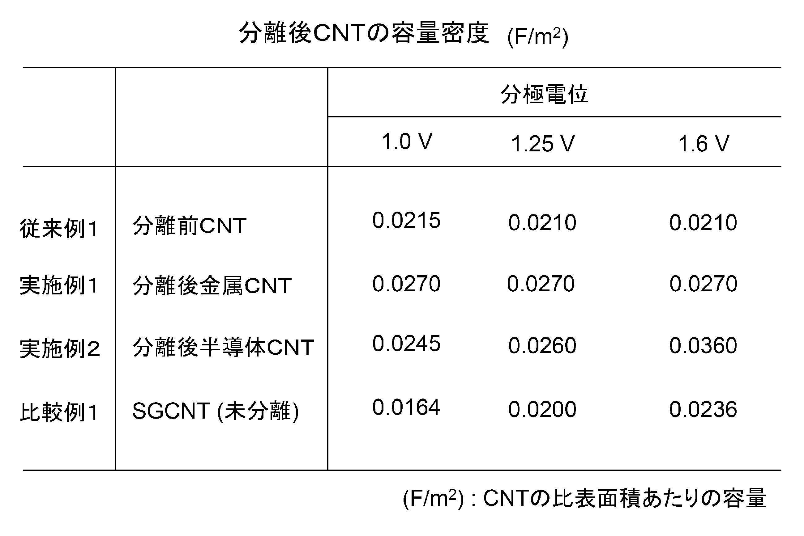
表1から明らかなように、分離前のカーボンナノチューブと比較して、分離後の金属性CNT、半導体性CNT共に、容量密度は増大した。また、分離後の半導体性CNTは、分極電位が大きくなるほど容量密度が増大した。一方、未分離のSGCNTでも分極電位が大きくなるほど容量密度が増大するが、単位面積当たりで比較すると、分離後の金属性CNT、半導体性CNTの方が容量密度は良好であった。
(2)キャパシタ特性
次に、上記のようにして得られたカーボンナノチューブ紛体に水を混ぜ、バインダーとしてカルボキシメチルセルロースナトリウムを加えた。それをPt基板にキャスト、乾燥することで簡易キャパシタ電極を作製した。この電極を作用極とし、対極に活性炭電極、参照電極にはAg/Ag+電極を用いた。電解液には1Mテトラエチルアンモニウムテトラフルオロボレートを溶解したプロピレンカーボネートを用い、サイクリックボルタモグラムを測定して電気化学的挙動およびキャパシタ特性を評価したところ、表2に示すような結果が得られた。
次に、上記のようにして得られたカーボンナノチューブ紛体に水を混ぜ、バインダーとしてカルボキシメチルセルロースナトリウムを加えた。それをPt基板にキャスト、乾燥することで簡易キャパシタ電極を作製した。この電極を作用極とし、対極に活性炭電極、参照電極にはAg/Ag+電極を用いた。電解液には1Mテトラエチルアンモニウムテトラフルオロボレートを溶解したプロピレンカーボネートを用い、サイクリックボルタモグラムを測定して電気化学的挙動およびキャパシタ特性を評価したところ、表2に示すような結果が得られた。
なお、電位走査範囲は-1.5Vから+1Vまで、電位走査速度は1mV/sとした。また、エネルギー密度は、電圧を2.5V又は3.2Vとし、サイクリックボルタモグラムの容量密度から算出した。
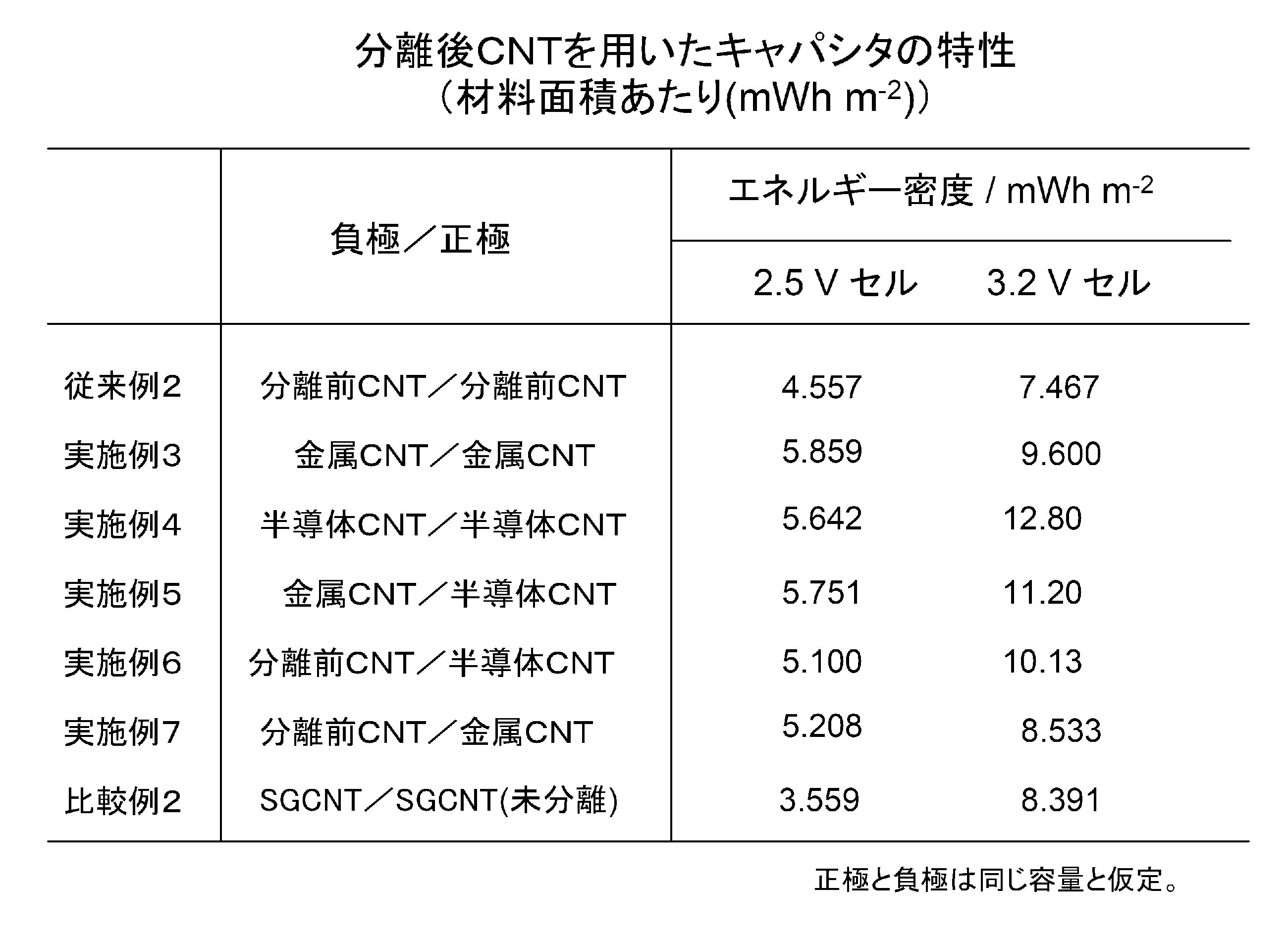
表2から明らかなように、負極/正極に分離後の金属CNT又は半導体性CNTを用いた実施例3~実施例5においては、分離前CNTを用いた従来例2と比較して、エネルギー密度は大幅に増大した。また、負極/正極の少なくともいずれかに分離後の半導体性CNTを用いた実施例4と実施例5においては、分極電位が大きくなるほどエネルギー密度は大幅に増大した。特に、両極に分離後の半導体性CNTを用いた実施例4においては、電圧が3.2Vの場合のエネルギー密度は、2.5Vの場合の約2.3倍に増大した。
また、負極/正極の一方にだけ分離後の金属CNT又は半導体性CNTを用いた実施例6及び実施例7においても、両極に分離前CNTを用いた従来例2と比較して、エネルギー密度は大幅に増大した。さらに、両極に未分離のSGCNTを用いた比較例2においては、電圧が3.2Vの場合のエネルギー密度は、2.5Vの場合の約2.4倍に増大したものの、実施例3~実施例7に比べてエネルギー密度は低かった。
以上の結果から、電気化学キャパシタの電極に用いるカーボンとして、分離後の金属性CNT及び/又は半導体性CNTを用いることが望ましく、一対の電極を電解質層を介して対向させた電気化学キャパシタにおいて、電極の少なくとも一方が半導体性CNT又は金属性CNTであることが望ましいことが分かった。
続いて、上記のようにして調製した半導体性CNTを用い、上記特許文献1に記載した方法により電気二重層キャパシタ用電極を作製した。この電極のエネルギー密度を調べたところ、以下のような結果が得られた。
(実施例8)
半導体性CNTを約50mg計り取り、50mlのメタノールと混合させ、汎用のミキサーで約30秒間撹拌させ、半導体性CNT/メタノール分散液を作製した。この分散液をPTFE濾紙(直径:35mm、平均細孔0.2μm)を用いて減圧ろ過し、抄紙成型した半導体性CNTシートを得た。これを集電体と同じサイズに切り取り、集電体となるエッチング処理したアルミ箔の上に載せ、それをアルミ箔で挟み、箔の上下方向から10t/cm2の圧力で1分間プレスした。
半導体性CNTを約50mg計り取り、50mlのメタノールと混合させ、汎用のミキサーで約30秒間撹拌させ、半導体性CNT/メタノール分散液を作製した。この分散液をPTFE濾紙(直径:35mm、平均細孔0.2μm)を用いて減圧ろ過し、抄紙成型した半導体性CNTシートを得た。これを集電体と同じサイズに切り取り、集電体となるエッチング処理したアルミ箔の上に載せ、それをアルミ箔で挟み、箔の上下方向から10t/cm2の圧力で1分間プレスした。
この電極を両極に用い、セルロース系セパレータを介して電気二重層キャパシタ素子を作製した(電極面積:2.1cm2)。そして、1M(=1mol/dm3)の四フッ化ホウ酸テトラエチルアンモニウムを含むプロピレンカーボネート溶液を電解液として素子に含浸させた後、ラミネートフィルムを用いて熱封止し、評価用セルを作製した。
(比較例3)
上記実施例8の半導体性CNTにかえて未分離のCNTを用いて、実施例8と同様にして、評価用セルを作製した。
上記実施例8の半導体性CNTにかえて未分離のCNTを用いて、実施例8と同様にして、評価用セルを作製した。
(試験結果)
これらの評価セルを用いて、3.2Vでのエネルギー密度を調べたところ、表3に示すような結果が得られた。

これらの評価セルを用いて、3.2Vでのエネルギー密度を調べたところ、表3に示すような結果が得られた。
表3から明らかなように、負極/正極に分離後の半導体性CNTを用いた実施例8においては、分離前CNTを用いた比較例3と比べてエネルギー密度は大幅に増大した。
Claims (4)
- 一対の電極を電解質層を介して対向させた電気化学キャパシタにおいて、
前記電極の少なくとも一方が、半導体性カーボンナノチューブからなる電極であることを特徴とする電気化学キャパシタ。 - 前記電極が、半導体性カーボンナノチューブを抄紙成型したシートを、集電体を構成し表面に凹凸部のある基材と、その凹凸部により一体化されたものであることを特徴とする請求項1に記載の電気化学キャパシタ。
- 一対の電極を電解質層を介して対向させた電気化学キャパシタにおいて、
前記電極の少なくとも一方が、金属性カーボンナノチューブからなる電極であることを特徴とする電気化学キャパシタ。 - 前記電極が、金属性カーボンナノチューブを抄紙成型したシートを、集電体を構成し表面に凹凸部のある基材と、その凹凸部により一体化されたものであることを特徴とする請求項3に記載の電気化学キャパシタ。
Applications Claiming Priority (2)
| Application Number | Priority Date | Filing Date | Title |
|---|---|---|---|
| JP2011047394A JP2012186264A (ja) | 2011-03-04 | 2011-03-04 | 電気化学キャパシタ |
| JP2011-047394 | 2011-03-04 |
Publications (1)
| Publication Number | Publication Date |
|---|---|
| WO2012121050A1 true WO2012121050A1 (ja) | 2012-09-13 |
Family
ID=46798018
Family Applications (1)
| Application Number | Title | Priority Date | Filing Date |
|---|---|---|---|
| PCT/JP2012/054847 Ceased WO2012121050A1 (ja) | 2011-03-04 | 2012-02-27 | 電気化学キャパシタ |
Country Status (2)
| Country | Link |
|---|---|
| JP (1) | JP2012186264A (ja) |
| WO (1) | WO2012121050A1 (ja) |
Citations (3)
| Publication number | Priority date | Publication date | Assignee | Title |
|---|---|---|---|---|
| JP2004304073A (ja) * | 2003-03-31 | 2004-10-28 | Keiko Waki | 電気化学キャパシタ |
| JP2007081384A (ja) * | 2005-08-19 | 2007-03-29 | National Institute Of Advanced Industrial & Technology | 電気化学キャパシタ及びそれに用いる電極材料 |
| JP2009099935A (ja) * | 2007-03-30 | 2009-05-07 | Nippon Chemicon Corp | 電気二重層キャパシタ用電極及びその製造方法 |
Family Cites Families (1)
| Publication number | Priority date | Publication date | Assignee | Title |
|---|---|---|---|---|
| JP2009023881A (ja) * | 2007-07-20 | 2009-02-05 | Panasonic Corp | カーボンナノチューブおよびカーボンナノチューブ構造体 |
-
2011
- 2011-03-04 JP JP2011047394A patent/JP2012186264A/ja active Pending
-
2012
- 2012-02-27 WO PCT/JP2012/054847 patent/WO2012121050A1/ja not_active Ceased
Patent Citations (3)
| Publication number | Priority date | Publication date | Assignee | Title |
|---|---|---|---|---|
| JP2004304073A (ja) * | 2003-03-31 | 2004-10-28 | Keiko Waki | 電気化学キャパシタ |
| JP2007081384A (ja) * | 2005-08-19 | 2007-03-29 | National Institute Of Advanced Industrial & Technology | 電気化学キャパシタ及びそれに用いる電極材料 |
| JP2009099935A (ja) * | 2007-03-30 | 2009-05-07 | Nippon Chemicon Corp | 電気二重層キャパシタ用電極及びその製造方法 |
Also Published As
| Publication number | Publication date |
|---|---|
| JP2012186264A (ja) | 2012-09-27 |
Similar Documents
| Publication | Publication Date | Title |
|---|---|---|
| Attia et al. | Supercapacitor electrode materials: addressing challenges in mechanism and charge storage | |
| Yu et al. | Recent progress in the development of anodes for asymmetric supercapacitors | |
| Cai et al. | Engineering of electrolyte ion channels in MXene/holey graphene electrodes for superior supercapacitive performances | |
| Srimuk et al. | Solid-type supercapacitor of reduced graphene oxide-metal organic framework composite coated on carbon fiber paper | |
| Huang et al. | Hybrid composite Ni (OH) 2@ NiCo2O4 grown on carbon fiber paper for high-performance supercapacitors | |
| CN113539696B (zh) | 用于储能装置的纳米结构化电极 | |
| Liu et al. | Nitrogen-doped reduced graphene oxide for high-performance flexible all-solid-state micro-supercapacitors | |
| Kumar et al. | Superbending (0–180°) and high-voltage operating metal-oxide-based flexible supercapacitor | |
| Hatzell et al. | Composite manganese oxide percolating networks as a suspension electrode for an asymmetric flow capacitor | |
| JP6213971B2 (ja) | グラフェン/CNT複合体電極装備Liイオン・スーパーキャパシター及びその製造方法 | |
| JP4706066B2 (ja) | 電気化学キャパシタ及びそれに用いる電極材料 | |
| Xie et al. | Electrochemical performance of carbon paper supercapacitor using sodium molybdate gel polymer electrolyte and nickel molybdate electrode | |
| US20110013344A1 (en) | Polarizable electrode for capacitor and electric double layer capacitor having the same | |
| JP5303235B2 (ja) | 電気二重層キャパシタ用電極及びその製造方法 | |
| JP2014093412A (ja) | ポリアニリン/グラフェン複合体およびそれを用いた電極材料 | |
| Yue et al. | Fabrication of flexible nanoporous nitrogen-doped graphene film for high-performance supercapacitors | |
| Haldar | Use of redox additive to enhance the electrochemical performance of Co3O4/polyaniline/graphene composite-based supercapacitors | |
| CN106430156A (zh) | 多孔石墨烯的制备、由此得到的多孔石墨烯及其应用 | |
| Kwon et al. | Graphite–graphene architecture for Zn-ion hybrid supercapacitor electrodes | |
| JP5458505B2 (ja) | 電気二重層キャパシタ用電極及びその製造方法 | |
| JP5304153B2 (ja) | 電気二重層キャパシタ用電極及びその製造方法 | |
| Mirzaee et al. | Facile synthesis of nano dendrite-structured Ni–NiO foam/ERGO by constant current method for supercapacitor applications | |
| Lv et al. | Battery-type NiMoO4@ NiMoS4 composite electrodes for high-performance supercapacitors | |
| Wang et al. | Supercapacitors based on highly dispersed polypyrrole-reduced graphene oxide composite with a folded surface | |
| CN102867653A (zh) | 一种三电极超级电容器 |
Legal Events
| Date | Code | Title | Description |
|---|---|---|---|
| 121 | Ep: the epo has been informed by wipo that ep was designated in this application |
Ref document number: 12755213 Country of ref document: EP Kind code of ref document: A1 |
|
| NENP | Non-entry into the national phase |
Ref country code: DE |
|
| 122 | Ep: pct application non-entry in european phase |
Ref document number: 12755213 Country of ref document: EP Kind code of ref document: A1 |