WO2012120744A1 - 電圧生成装置、電圧生成方法およびコンデンサ装置 - Google Patents
電圧生成装置、電圧生成方法およびコンデンサ装置 Download PDFInfo
- Publication number
- WO2012120744A1 WO2012120744A1 PCT/JP2011/079019 JP2011079019W WO2012120744A1 WO 2012120744 A1 WO2012120744 A1 WO 2012120744A1 JP 2011079019 W JP2011079019 W JP 2011079019W WO 2012120744 A1 WO2012120744 A1 WO 2012120744A1
- Authority
- WO
- WIPO (PCT)
- Prior art keywords
- coil
- reactor
- voltage
- capacitor
- capacitor device
- Prior art date
- Legal status (The legal status is an assumption and is not a legal conclusion. Google has not performed a legal analysis and makes no representation as to the accuracy of the status listed.)
- Ceased
Links
Images


Classifications
-
- H—ELECTRICITY
- H01—ELECTRIC ELEMENTS
- H01F—MAGNETS; INDUCTANCES; TRANSFORMERS; SELECTION OF MATERIALS FOR THEIR MAGNETIC PROPERTIES
- H01F27/00—Details of transformers or inductances, in general
- H01F27/28—Coils; Windings; Conductive connections
- H01F27/30—Fastening or clamping coils, windings, or parts thereof together; Fastening or mounting coils or windings on core, casing, or other support
-
- H—ELECTRICITY
- H02—GENERATION; CONVERSION OR DISTRIBUTION OF ELECTRIC POWER
- H02J—ELECTRIC POWER NETWORKS; CIRCUIT ARRANGEMENTS OR SYSTEMS FOR SUPPLYING OR DISTRIBUTING ELECTRIC POWER; SYSTEMS FOR STORING ELECTRIC ENERGY
- H02J50/00—Circuit arrangements or systems for wireless supply or distribution of electric power
- H02J50/005—Mechanical details of housing or structure aiming to accommodate the power transfer means, e.g. mechanical integration of coils, antennas or transducers into emitting or receiving devices
-
- H—ELECTRICITY
- H02—GENERATION; CONVERSION OR DISTRIBUTION OF ELECTRIC POWER
- H02J—ELECTRIC POWER NETWORKS; CIRCUIT ARRANGEMENTS OR SYSTEMS FOR SUPPLYING OR DISTRIBUTING ELECTRIC POWER; SYSTEMS FOR STORING ELECTRIC ENERGY
- H02J50/00—Circuit arrangements or systems for wireless supply or distribution of electric power
- H02J50/10—Circuit arrangements or systems for wireless supply or distribution of electric power using inductive coupling
- H02J50/12—Circuit arrangements or systems for wireless supply or distribution of electric power using inductive coupling of the resonant type
-
- H—ELECTRICITY
- H02—GENERATION; CONVERSION OR DISTRIBUTION OF ELECTRIC POWER
- H02J—ELECTRIC POWER NETWORKS; CIRCUIT ARRANGEMENTS OR SYSTEMS FOR SUPPLYING OR DISTRIBUTING ELECTRIC POWER; SYSTEMS FOR STORING ELECTRIC ENERGY
- H02J50/00—Circuit arrangements or systems for wireless supply or distribution of electric power
- H02J50/70—Circuit arrangements or systems for wireless supply or distribution of electric power involving the reduction of electric, magnetic or electromagnetic leakage fields
-
- H—ELECTRICITY
- H02—GENERATION; CONVERSION OR DISTRIBUTION OF ELECTRIC POWER
- H02J—ELECTRIC POWER NETWORKS; CIRCUIT ARRANGEMENTS OR SYSTEMS FOR SUPPLYING OR DISTRIBUTING ELECTRIC POWER; SYSTEMS FOR STORING ELECTRIC ENERGY
- H02J11/00—Circuit arrangements for providing service supply to auxiliaries of stations in which electric power is generated, distributed or converted
Definitions
- the present invention relates to a voltage generation device and a voltage generation method for an auxiliary power supply, for example, and particularly to a voltage generation device and a voltage generation method capable of generating a voltage from a high-voltage power capacitor device.
- Patent Document 1 discloses a capacitor device including a series resonance circuit of a capacitor and a reactor.
- the capacitor device must have a function of detecting an abnormality caused by deterioration over time. Conventionally, especially in small-capacitance capacitor devices, there is no need for external power supply, such as bimetallic temperature contacts, pressure contacts, and fuses. The anomaly detection means was favorably used. Such a capacitor device is disclosed in Patent Document 2 and Patent Document 3, for example.
- an abnormal state of the capacitor device is detected at a plurality of stages, and different control is performed according to the detected abnormal state stage.
- an electronic circuit that receives a state signal indicating the state of the capacitor device and determines an abnormal state from the state signal is separately required.
- Small-capacity power capacitor devices have strict cost requirements, and there is a background that power supply from the outside is avoided because it leads to cost increase.
- a small-capacity power capacitor device has an equipment life of 10 years or more with almost no maintenance, and the temperature inside the device is 50 ° C. or higher, so it is extremely difficult to use a battery as a power source. For this reason, in a capacitor device of a power receiving facility that uses high voltage power, it is difficult to obtain a small auxiliary power source for the electronic circuit when an electronic circuit for performing advanced protection is to be mounted. is there.
- the present invention has been made in view of the above problems, and is applied to a capacitor device of a power receiving facility using high-voltage power, and a voltage generating device capable of obtaining an auxiliary power source for an electronic circuit for performing advanced protection, and An object is to provide a voltage generation method.
- the voltage generation device of the present invention is a voltage generation device that generates a voltage from a capacitor device including a series resonance circuit of a capacitor and a reactor, and from a magnetic field generated by the reactor by electromagnetic induction. It includes a coil part for generating an electromotive force, and the coil part has a connector part capable of separating and connecting the coil part at at least one place.
- the coil portion when the coil portion is arranged around the iron core of the reactor, the coil portion receives an action of electromagnetic induction from an AC magnetic field generated in the iron core to generate an AC electromotive force. If the alternating current generated in the coil portion is rectified and smoothed, it can be used as a power supply voltage for an electronic circuit that performs protection control of the capacitor device.
- the coil part has a connector part at at least one place, and is arranged so as to sandwich the core of the reactor in a state where the connector part is separated, and then connecting the connector part, It becomes easy to surround and arrange the iron core of the reactor. For this reason, the voltage generation device including the coil unit can be easily attached to the existing capacitor device without any influence, and the power supply voltage for the electronic circuit can be easily taken out.
- the coil part has at least two or more connector parts, and the coil part can be divided into a plurality of wiring parts that form a part of the coil part. It can be configured.
- the said coil part can be divided
- the voltage generation method of the present invention is a voltage generation method for generating a voltage from a capacitor device including a series resonance circuit of a capacitor and a reactor in order to solve the above-described problem, and the presence of a magnetic field generated in the reactor
- a coil portion is disposed in the region, and a voltage is generated by extracting an electromotive force generated in the coil portion by electromagnetic induction caused by the action of the magnetic field.
- the said coil part receives the effect
- the coil unit has a connector unit that can separate and connect the coil unit at at least one location, and the coil unit is separated from the connector unit. It arrange
- the coil part is arranged so as to sandwich the core of the reactor in a state where the connector part is separated, and thereafter, the coil part is easily attached to the iron core by connecting the connector part. For this reason, the voltage generation device including the coil unit can be easily attached to the existing capacitor device without any influence, and the power supply voltage for the electronic circuit can be easily taken out.
- the core of the reactor has a ground potential
- the coil portion is preferably disposed along a region within 5 mm from the surface of the core of the reactor. As a result, the coil portion is disposed close to the ground potential member and can be attached without affecting the insulation performance of the main circuit of the reactor.
- the capacitor device of the present invention is a capacitor device including a series resonance circuit of a capacitor and a reactor, and the main core for configuring the series resonance circuit is provided on the core of the reactor. Apart from the coil, an auxiliary power supply coil is wound.
- the auxiliary power supply coil generates an AC electromotive force from the AC magnetic field generated in the reactor under the action of electromagnetic induction. If the alternating current generated in the auxiliary power supply coil is rectified and smoothed, it can be used as a power supply voltage for an electronic circuit that performs protection control of the capacitor device.
- the voltage generation device of the present invention is a voltage generation device that generates a voltage from a capacitor device including a series resonance circuit of a capacitor and a reactor, and includes a coil unit that generates an electromotive force by electromagnetic induction from a magnetic field generated by the reactor.
- the coil portion has a connector portion that can separate and connect the coil portion at at least one location.
- the coil section is arranged around the core of the reactor, and generates an AC electromotive force by receiving an electromagnetic induction action from an AC magnetic field generated in the core.
- the coil portion has a connector portion at at least one place, there is an effect that it can be easily attached to an existing capacitor device without any influence.
- the capacitor device to which the voltage generating device according to the first embodiment can be attached is a capacitor device including a series resonance circuit of a capacitor 20 and a reactor 30, as shown in FIG.
- Reactor 30 includes a coil and an iron core for enhancing a magnetic field generated when a current flows through the coil.
- a schematic structure of the reactor 30 is shown in FIG.
- the voltage generation device includes a coil unit disposed in a region where a magnetic field generated in the reactor 30 is present, and extracts an electromotive force generated in the coil unit by electromagnetic induction caused by the action of the magnetic field. That is, since the reactor 30 constitutes a resonance circuit together with the capacitor 20, the current flowing through the coil of the reactor 30 is an alternating current, and the generated magnetic field is also an alternating magnetic field. When the coil is arranged so that the magnetic flux of the AC magnetic field penetrates through the inside, an AC electromotive force is generated in the coil by electromagnetic induction.
- the coil section in the voltage generating apparatus according to the first embodiment may be disposed anywhere as long as it is an area where a magnetic field generated by the coil of the reactor 30 exists.
- a high-density magnetic flux is generated in the iron core 31 of the reactor 30, it is preferable to have a structure in which a coil portion is arranged around the iron core 31. In this way, a large electromotive force can be obtained with a simple coil, which is most practical. For this reason, in this Embodiment 1, the voltage generation apparatus of the structure which distributes a coil part around the iron core 31 of the reactor 30 is demonstrated.
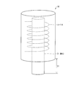
- FIG. 1 is a diagram illustrating a main configuration of the voltage generation apparatus 10 according to the first embodiment.
- the voltage generating device 10 includes a first wiring part 11 that forms a part of the coil and a second wiring part 12 that forms the remaining part of the coil.
- the first wiring portion 11 and the second wiring portion 12 have two connector portions 11a and 12a, respectively, and the coil portions can be separated and connected by the connector portions.
- the 1st wiring part 11 and the 2nd wiring part 12 comprise the coil part of the voltage generation apparatus 10 by connecting the connector parts 11a and 12a in two places. Both ends of the wiring constituting the coil part are drawn to the outside, and a voltage generated in the coil part by electromagnetic induction can be taken out.
- the first wiring portion 11 and the second wiring portion 12 are separated from each other, and the iron core 31 of the reactor 30 is sandwiched between them so as to be connected by a connector.
- the coil part of the voltage generation apparatus 10 is formed around the iron core 31, and an electromotive force is generated in the coil part according to the principle described above. If the generated electromotive force is rectified and smoothed by the rectifier circuit 13, it can be sufficiently used as an auxiliary power source for a power supply circuit that performs protection control of the capacitor device.
- the rectifier circuit 13 a rectifier circuit having a known configuration can be used.
- the rectifier circuit 13 may be included in the voltage generator 10 or may be externally connected.
- the voltage generator 10 can arrange the coil part that can be divided by the connector part around the iron core 31 of the reactor 30, and the dielectric current generated in the coil part can be used as an auxiliary power source for an electronic circuit. To do.
- the voltage generation device 10 can be easily attached to an existing capacitor device, and does not affect the shape for securing the insulation performance in the reactor 30 and the manufacturing (molding) process.
- the voltage generator 10 can be easily formed. Further, in the voltage generation device 10 using a printed circuit board as a wiring board, since the windings of the coil portions are arranged in the radial direction of the iron core, the thickness (thickness in the axial direction of the iron core) is reduced to about 2 to 3 mm. it can.
- the coil in the reactor 30 is molded insulatively, and a gap (see FIG. 3) D1 from the lower part of the molded part to the lower end of the iron core 31 is a narrow gap of about 20 to 30 mm.
- the voltage generator 10 is arranged in the gap D1, but if the voltage generator 10 is as thin as 2 to 3 mm, it can be easily arranged in the gap D1.
- the voltage generator 10 has two connector connections and can be divided into two parts. It is good also as a structure which can be opened.
- a flat cable is used for wiring of the coil portion, and flexibility is given to the coil portion.
- the coil part of a voltage generation apparatus is formed by winding a flat cable around the iron core 31 in the state which removed the connector connection, and connecting a connector after that.
- the axial width of the iron core is slightly increased as compared with the case where a printed circuit board is used for the wiring of the coil portion, but the cost reduction of the voltage generating device can be expected by reducing the connector portion.
- segment into three or more parts may be sufficient.
- the coil portion of the voltage generation device is disposed close to the ground potential member because it can be attached without affecting the insulation performance of the main circuit of the reactor. .
- the core of the reactor is set to ground potential.
- the wiring of a coil part is arrange
- region within 5 mm from the iron core surface of a reactor (L1 ⁇ 5mm: refer FIG. 1).
- the coil portion of the voltage generator may be configured to be electrostatically shielded by a grounded conductor. This also allows the voltage generator to be attached without affecting the insulation performance of the reactor main circuit.
- a reactor can be provided for each of the U-phase, V-phase, and W-phase currents.
- the voltage generation device 10 shown in FIG. 1 may be attached to the core of a reactor of at least one of these three phases (for example, U phase). Or the coil part of a voltage generation apparatus may be attached to two phases or three phases among three phases.
- the rectifier circuit needs to correspond to it. In such a rectifier circuit, a rectifier circuit having a known configuration can be used.
- the voltage for the auxiliary power source was generated using the voltage generating apparatus having the configuration shown in FIG.
- the cross-sectional area of the core of the reactor is 20 cm 2
- the magnetic flux density generated in the core is about 1 Tesla (rms)
- the number of turns of the coil portion of the voltage generator is 10 turns.
- an electromotive force of 0.6 Vrms is obtained in one turn, and 6.0 Vrms in 10 turns.
- this was full-wave rectified, smoothed with an electrolytic capacitor, and 5 V was obtained with a three-terminal regulator. This DC 5V power supply voltage is sufficient to drive an electronic circuit for enhancing the protection and smartness of the capacitor device.
- the present invention can be realized as a capacitor device in which the voltage generating device of the present invention is mounted in advance as means for providing auxiliary power.
- the auxiliary power supply coil is wound in advance separately from the coil for the main circuit (the main coil for configuring the series resonant circuit together with the capacitor) on the core of the reactor,
- the voltage generated by the auxiliary power supply coil can be used as the auxiliary power supply.
- the auxiliary power supply coil and the main circuit coil need to be insulated from each other, the conventional shape and the manufacturing (molding) process are not particularly affected in obtaining the insulation performance. For this reason, the auxiliary power supply coil can be easily mounted in the capacitor device.
- the present invention can generate a voltage from a high-voltage power capacitor device, and can be used, for example, as an auxiliary power source for an electronic circuit that protects a capacitor.
Landscapes
- Engineering & Computer Science (AREA)
- Power Engineering (AREA)
- Computer Networks & Wireless Communication (AREA)
- Physics & Mathematics (AREA)
- Electromagnetism (AREA)
- Rectifiers (AREA)
Abstract
高圧電力を用いる受電設備のコンデンサ装置において適用され、高度な保護を行うための電子回路用の補助電源を得ることのできる電圧生成装置および電圧生成方法を提供する。 電圧生成装置10は、電磁誘導によって生じる電圧を取り出すことが可能なコイル部を含み、上記コイル部の一部分を形成する第1配線部11と、上記コイル部の残りの部分を形成する第2配線部12とを有している。また、第1配線部11および第2配線部12は、それぞれ2箇所のコネクタ部11aおよび12aを有しており、該コネクタ部によってコイル部を分離および接続が可能となっている。電圧生成装置10をコンデンサ装置に取り付けるときには、第1配線部11と第2配線部12とが分割された状態から、上記コンデンサ装置のリアクトルの鉄心31を挟み込むようにしてこれらをコネクタ接続する。
Description
本発明は、例えば補助電源用の電圧生成装置および電圧生成方法に関し、特に、高圧電力コンデンサ装置から電圧を生成することが可能な電圧生成装置および電圧生成方法に関する。
高圧(例えば6.6kV)の電力を用いる受電設備や施設では、力率を改善する調相設備としてコンデンサ装置を備えることが一般的である。例えば、特許文献1では、コンデンサおよびリアクトルの直列共振回路からなるコンデンサ装置が開示されている。
上記コンデンサ装置は、経年劣化等によって生じる異常を検出する機能を有する必要がある。従来、特に小容量のコンデンサ装置では、バイメタルによる温度接点や、圧力接点やヒューズのような、外部から電力供給の必要が無い、電子回路によらない、自己完結型の、安価でシンプルな動作原理の異常検出手段が好んで用いられていた。このようなコンデンサ装置は、例えば特許文献2や特許文献3において開示されている。
上記のような自己完結型の異常検出手段を用いた場合、コンデンサ内の圧力や温度が限度値を超えたときにこれを検知し、この検知に基づいて大元の電源からコンデンサ装置を遮断するといった制御が行われる。
また、近年では、システムのインテリジェント化およびスマート化への要求が高くなっており、コンデンサ装置の保護においてもより高度な制御を行いたいといった要求がある。この場合は、コンデンサ装置の異常状態を複数の段階で検出し、検出された異常状態の段階に応じて異なる制御を行う。このような高度な保護を行うためには、コンデンサ装置の状態を示す状態信号を受信し、その状態信号から異常状態を判断する電子回路が別途必要となる。
しかしながら、コンデンサ装置において、電子回路を用いたより高度な保護を行おうとする場合には、上記電子回路に対する動作電源の供給の問題がある。これは以下の理由による。
小容量の電力コンデンサ装置では、コスト要求が厳しく、外部から電源供給を行うことはコスト上昇に繋がるため敬遠されるといった背景がある。また、小容量の電力コンデンサ装置は殆どメンテナンスされることなく十年以上の設備寿命をもち、しかも装置内は50℃以上の温度になるため、電源として電池を用いることも極めて困難である。このため、高圧電力を用いる受電設備のコンデンサ装置では、高度な保護を行うための電子回路を搭載しようとすると、その電子回路のための僅かな補助電源を得ることが困難であるのが現状である。
本願発明は、上記課題に鑑みてなされたものであり、高圧電力を用いる受電設備のコンデンサ装置において適用され、高度な保護を行うための電子回路用の補助電源を得ることのできる電圧生成装置および電圧生成方法を提供することを目的とする。
本発明の電圧生成装置は、上記の課題を解決するために、コンデンサおよびリアクトルの直列共振回路を含むコンデンサ装置から電圧を生成する電圧生成装置であって、上記リアクトルによって生じる磁界から、電磁誘導によって起電力を生じさせるコイル部を含み、上記コイル部は、少なくとも1箇所で該コイル部を分離および接続が可能なコネクタ部を有していることを特徴としている。
上記の構成によれば、上記コイル部は、上記リアクトルの鉄心の周りに配置された場合、上記鉄心に生じる交流磁界から、電磁誘導の作用を受けて交流起電力を発生させる。上記コイル部に生じた交流電流を整流および平滑化すれば、上記コンデンサ装置の保護制御を行う電子回路の電源電圧として使用することが可能となる。
また、上記コイル部は、少なくとも1箇所でコネクタ部を有しており、該コネクタ部が分離された状態で上記リアクトルの鉄心を挟み込むように配置され、その後、上記コネクタ部を接続することで、上記リアクトルの鉄心を取り囲んで配置することが容易となる。このため、上記コイル部を含む電圧生成装置は、既存のコンデンサ装置に対して、何ら影響を与えることなく容易に取り付け可能であり、電子回路用の電源電圧を容易に取り出すことができる。
また、上記電圧生成装置では、上記コイル部は、少なくとも2箇所以上の上記コネクタ部を有しており、上記コイル部は、上記コイル部の一部を形成する複数の配線部に分割可能である構成とすることができる。
上記の構成によれば、上記コイル部は、複数の配線部に分割可能であることから、これらの配線部を、例えばプリント基板等の可撓性の無い部材で形成した場合であっても、既存のコンデンサ装置に対してコイル部を取り付けることが容易となる。
また、本発明の電圧生成方法は、上記の課題を解決するために、コンデンサおよびリアクトルの直列共振回路を含むコンデンサ装置から電圧を生成する電圧生成方法であって、上記リアクトルにおいて発生する磁界の存在領域にコイル部を配置し、上記磁界の作用による電磁誘導によって上記コイル部に生じる起電力を取り出すことで電圧を生成することを特徴としている。
上記の構成によれば、上記コイル部は、上記リアクトルにおいて生じる交流磁界から、電磁誘導の作用を受けて交流起電力を発生させる。上記コイル部に生じた交流電流を整流および平滑化すれば、上記コンデンサ装置の保護制御を行う電子回路の電源電圧として使用することが可能となる。
また、上記電圧生成方法では、上記コイル部は、少なくとも1箇所で該コイル部を分離および接続が可能なコネクタ部を有しており、上記コイル部は、上記コネクタ部が分離された状態で上記リアクトルの鉄心を挟み込むように配置され、その後、上記コネクタ部を接続することで、上記リアクトルの鉄心を取り囲んで配置される構成とすることができる。
また、上記コイル部は、上記コネクタ部が分離された状態で上記リアクトルの鉄心を挟み込むように配置され、その後、上記コネクタ部を接続することで、上記鉄心に対して容易に取り付けられる。このため、上記コイル部を含む電圧生成装置は、既存のコンデンサ装置に対して、何ら影響を与えることなく容易に取り付け可能であり、電子回路用の電源電圧を容易に取り出すことができる。
また、上記電圧生成方法では、上記リアクトルの鉄心は接地電位を有しており、上記コイル部は、リアクトルの鉄心表面から5mm以内の領域に沿って配置されることが好ましい。これにより、上記コイル部が接地電位部材に近接して配置され、リアクトルの主回路の絶縁性能に影響を与えずに取り付けることができる。
また、本発明のコンデンサ装置は、上記の課題を解決するために、コンデンサおよびリアクトルの直列共振回路を含むコンデンサ装置であって、上記リアクトルの鉄心には、上記直列共振回路を構成するための主コイルとは別に、補助電源用コイルが巻回されていることを特徴としている。
上記の構成によれば、上記補助電源用コイルは、上記リアクトルにおいて生じる交流磁界から、電磁誘導の作用を受けて交流起電力を発生させる。上記補助電源用コイルに生じた交流電流を整流および平滑化すれば、上記コンデンサ装置の保護制御を行う電子回路の電源電圧として使用することが可能となる。
本発明の電圧生成装置は、コンデンサおよびリアクトルの直列共振回路を含むコンデンサ装置から電圧を生成する電圧生成装置であって、上記リアクトルによって生じる磁界から、電磁誘導によって起電力を生じさせるコイル部を含み、上記コイル部は、少なくとも1箇所で該コイル部を分離および接続が可能なコネクタ部を有している構成である。
それゆえ、上記コイル部は、上記リアクトルの鉄心の周りに配置されることで、上記鉄心に生じる交流磁界から、電磁誘導の作用を受けて交流起電力を発生させる。この交流起電力を電子回路用の電源電圧として使用することで、外部から電源供給を行うことなく、コンデンサ装置に対して電子回路を用いた高度な保護を行うことができるといった効果を奏する。
また、上記コイル部は、少なくとも1箇所でコネクタ部を有しているため、既存のコンデンサ装置に対して、何ら影響を与えることなく容易に取り付け可能であるといった効果を奏する。
以下、本発明の実施形態について、図面に基づいて詳細に説明する。
〔実施形態1〕
本実施形態1では、既存のコンデンサ装置に対して簡易に取り付け可能であり、該コンデンサ装置から補助電源用の電圧を取り出すことのできる電圧生成装置および電圧生成方法を説明する。まずは、本実施形態1に係る電圧生成装置を取り付け可能なコンデンサ装置について簡単に説明する。
本実施形態1では、既存のコンデンサ装置に対して簡易に取り付け可能であり、該コンデンサ装置から補助電源用の電圧を取り出すことのできる電圧生成装置および電圧生成方法を説明する。まずは、本実施形態1に係る電圧生成装置を取り付け可能なコンデンサ装置について簡単に説明する。
本実施形態1に係る電圧生成装置を取り付け可能なコンデンサ装置は、図2に示すように、コンデンサ20およびリアクトル30の直列共振回路を含むコンデンサ装置である。リアクトル30は、コイルと、コイルに電流が流れたときに発生する磁界を増強するための鉄心とを有している。リアクトル30の概略構造を図3に示す。
本実施形態1に係る電圧生成装置は、リアクトル30において発生する磁界の存在領域に配置されるコイル部を有し、磁界の作用による電磁誘導によってコイル部に生じる起電力を取り出す。すなわち、リアクトル30はコンデンサ20と共に共振回路を構成するため、リアクトル30のコイルに流れる電流は交流であり、発生する磁界も交流磁界である。この交流磁界の磁束がその内部を貫くようにコイルが配置されると、そのコイルには電磁誘導によって交流起電力が発生する。
本実施形態1に係る電圧生成装置におけるコイル部は、原理的には、リアクトル30のコイルによって発生する磁界の存在領域であれば、どこに配置されていてもよい。但し、リアクトル30の鉄心31には高密度の磁束が発生するため、鉄心31の周囲にコイル部を配する構造とすることが好ましい。こうすれば、簡易なコイルで大きな起電力を得ることができ、最も実用的である。このため、本実施形態1では、リアクトル30の鉄心31の周囲にコイル部を配する構造の電圧生成装置を説明する。
図1は、本実施形態1に係る電圧生成装置10の要部構成を示す図である。電圧生成装置10は、コイルの一部分を形成する第1配線部11とコイルの残りの部分を形成する第2配線部12とを有する。また、第1配線部11および第2配線部12は、それぞれ2箇所のコネクタ部11aおよび12aを有しており、該コネクタ部によってコイル部を分離および接続が可能となっている。第1配線部11および第2配線部12は、2箇所でコネクタ部11aおよび12a同士を接続することによって電圧生成装置10のコイル部を構成する。コイル部を構成する配線両端は外部に引き出され、電磁誘導によって該コイル部に生じる電圧を取り出すことが可能となっている。
電圧生成装置10をコンデンサ装置に取り付けるときには、第1配線部11と第2配線部12とが分割された状態から、リアクトル30の鉄心31を挟み込むようにしてこれらをコネクタ接続する。これにより、鉄心31の周囲に電圧生成装置10のコイル部が形成され、上述した原理によって該コイル部に起電力が発生する。発生した起電力は、整流回路13で整流し、平滑化すれば、コンデンサ装置の保護制御を行う電源回路用の補助電源として用いることが十分可能である。整流回路13には、周知の構成の整流回路を用いることができる。尚、整流回路13は、電圧生成装置10に含まれても良く、あるいは外部接続されても良い。
このように、電圧生成装置10は、コネクタ部によって分割可能としたコイル部をリアクトル30の鉄心31の周囲に配置し、該コイル部に発生する誘電電流を電子回路用の補助電源として利用可能にする。電圧生成装置10は、既存のコンデンサ装置に対して簡易に取り付けることができ、リアクトル30における絶縁性能を確保するための形状や製造(成形)過程に影響を与えない。
第1配線部11および第2配線部12における配線部分にプリント基板を用い、コネクタ部11aおよび12aに多芯コネクタを用いれば、電圧生成装置10は容易に形成できる。また、配線基板にプリント基板を用いた電圧生成装置10は、コイル部の各巻回が、鉄心の径方向に並ぶため、その厚さ(鉄心の軸方向の厚さ)を2~3mm程度に薄くできる。
一般的な高圧電力コンデンサ装置では、リアクトル30のコイルにも高圧電流が流れるため、当然ながら高い絶縁性が要求される。このため、リアクトル30におけるコイルは絶縁的にモールドされており、このモールド部の下部から鉄心31の下端までの隙間(図3参照)D1は20~30mm程度の狭い隙間となっている。電圧生成装置10は、上記隙間D1に配置されるが、電圧生成装置10の厚さが2~3mm程度の薄さであれば、上記隙間D1に配置することも容易である。
また、図1の構成では、電圧生成装置10は2箇所のコネクタ接続を有しており、2つのパートに分割できるようになっているが、コネクタ接続を1箇所として、コイルを分割できずとも開放できる構成としても良い。この場合は、コイル部の配線に例えばフラットケーブルを用いコイル部に可撓性を与える。これにより、コネクタ接続を外した状態でフラットケーブルを鉄心31に巻き付け、その後コネクタを接続することで電圧生成装置のコイル部が形成される。この構成では、コイル部の配線にプリント基板を用いる場合に比べ、鉄心の軸方向の幅が若干増加するが、コネクタ部を減らすことで電圧生成装置のコスト削減が期待できる。あるいは、巻き付けやすいようにコネクタ接続箇所をさらに増やし、3つ以上のパートに分割できるような構成でも良い。
本実施形態1に係る電圧生成装置においては、電圧生成装置のコイル部が接地電位部材に近接して配置されると、リアクトルの主回路の絶縁性能に影響を与えずに取り付けることができるため好ましい。通常、リアクトルの鉄心は接地電位とされている。このため、コイル部の配線は、リアクトルの鉄心表面から5mm以内の領域に沿って配置されることが好ましい(L1≦5mm:図1参照)。
さらに、電圧生成装置のコイル部は、接地された導体にて静電シールドされる構成としても良い。これによっても、リアクトルの主回路の絶縁性能に影響を与えずに電圧生成装置を取り付けることができる。
尚、高圧電力を用いる受電設備では、3相交流が用いられることが多く、この場合、U相、V相、およびW相の電流のそれぞれに対してリアクトルを設けることができる。図1に示す電圧生成装置10は、これら3つの相の少なくとも一つ(例えばU相)のリアクトルの鉄心に取り付けられても良い。あるいは、3つの相のうち、2相または3相に電圧生成装置のコイル部が取り付けられても良い。2相または3相に電圧生成装置を取り付ける場合には、整流回路もそれに対応したものとする必要がある。尚、そのような整流回路においても、周知の構成の整流回路を用いることができる。
実際に図1の構成の電圧生成装置を用いて補助電源用電圧の生成を行った。このとき、リアクトルの鉄心の断面積は20cm2 、鉄心に生じる磁束密度は約1テスラ(rms)、電圧生成装置のコイル部の巻き数は10ターンである。その結果、1ターンで0.6Vrmsの起電力が得られ、10ターンでは6.0Vrmsとなる。整流回路では、これを全波整流し、電解コンデンサで平滑化し、3端子レギュレータで5Vを得た。この直流5Vの電源電圧は、コンデンサ装置の保護の高度化およびスマート化を行う電子回路を駆動するには十分な電圧である。
〔実施形態2〕
上記実施形態1では、既存のコンデンサ装置から補助電源電圧を取り出すことを重要な前提としているため、コンデンサ装置に後付けされる電圧生成装置として示されている。
上記実施形態1では、既存のコンデンサ装置から補助電源電圧を取り出すことを重要な前提としているため、コンデンサ装置に後付けされる電圧生成装置として示されている。
しかしながら、今後新たに製造される受電設備においては、補助電源の提供手段として本発明の電圧生成装置を予め搭載したコンデンサ装置として本発明を実現することも可能である。
すなわち、本実施形態2に係るコンデンサ装置では、リアクトルの鉄心に主回路用のコイル(コンデンサと共に直列共振回路を構成するための主コイル)とは別に、予め補助電源用コイルを巻回しておき、この補助電源用コイルによって生成される電圧を補助電源とすることができる。補助電源用コイルと主回路用のコイルとは互いに絶縁される必要はあるが、この絶縁性能を得るにあたって従来からの形状や製造(成形)工程に特に影響を与えることはない。このため、上記補助電源用コイルはコンデンサ装置において容易に搭載可能である。
本発明は上述した各実施形態に限定されるものではなく、請求項に示した範囲で種々の変更が可能であり、異なる実施形態にそれぞれ開示された技術的手段を適宜組み合わせて得られる実施形態についても本発明の技術的範囲に含まれる。
本出願は、2011年3月8日に提出された日本国特許出願(特願2011-050627)に基づくものであり、その内容はここに参照として取り込まれる。
本発明は、高圧電力コンデンサ装置から電圧を生成することができ、例えばコンデンサの保護を行う電子回路用の補助電源に利用することができる。
10 電圧生成装置
11 第1配線部(配線部)
11a コネクタ部
12 第2配線部(配線部)
12a コネクタ部
13 整流回路
20 コンデンサ
30 リアクトル
31 鉄心
11 第1配線部(配線部)
11a コネクタ部
12 第2配線部(配線部)
12a コネクタ部
13 整流回路
20 コンデンサ
30 リアクトル
31 鉄心
Claims (6)
- コンデンサおよびリアクトルの直列共振回路を含むコンデンサ装置から電圧を生成する電圧生成装置であって、
上記リアクトルによって生じる磁界から、電磁誘導によって起電力を生じさせるコイル部を含み、
上記コイル部は、少なくとも1箇所で該コイル部を分離および接続が可能なコネクタ部を有していることを特徴とする電圧生成装置。 - 上記コイル部は、少なくとも2箇所以上の上記コネクタ部を有しており、
上記コイル部は、上記コイル部の一部を形成する複数の配線部に分割可能であることを特徴とする請求項1に記載の電圧生成装置。 - コンデンサおよびリアクトルの直列共振回路を含むコンデンサ装置から電圧を生成する電圧生成方法であって、
上記リアクトルにおいて発生する磁界の存在領域にコイル部を配置し、上記磁界の作用による電磁誘導によって上記コイル部に生じる起電力を取り出すことで電圧を生成することを特徴とする電圧生成方法。 - 上記コイル部は、少なくとも1箇所で該コイル部を分離および接続が可能なコネクタ部を有しており、
上記コイル部は、上記コネクタ部が分離された状態で上記リアクトルの鉄心を挟み込むように配置され、その後、上記コネクタ部を接続することで、上記リアクトルの鉄心を取り囲んで配置されることを特徴とする請求項3に記載の電圧生成方法。 - 上記リアクトルの鉄心は接地電位を有しており、
上記コイル部は、リアクトルの鉄心表面から5mm以内の領域に沿って配置されることを特徴とする請求項4に記載の電圧生成方法。 - コンデンサおよびリアクトルの直列共振回路を含むコンデンサ装置であって、
上記リアクトルの鉄心には、上記直列共振回路を構成するための主コイルとは別に、補助電源用コイルが巻回されていることを特徴とするコンデンサ装置。
Applications Claiming Priority (2)
| Application Number | Priority Date | Filing Date | Title |
|---|---|---|---|
| JP2011050627A JP2012191678A (ja) | 2011-03-08 | 2011-03-08 | 電圧生成装置、電圧生成方法およびコンデンサ装置 |
| JP2011-050627 | 2011-03-08 |
Publications (1)
| Publication Number | Publication Date |
|---|---|
| WO2012120744A1 true WO2012120744A1 (ja) | 2012-09-13 |
Family
ID=46797725
Family Applications (1)
| Application Number | Title | Priority Date | Filing Date |
|---|---|---|---|
| PCT/JP2011/079019 Ceased WO2012120744A1 (ja) | 2011-03-08 | 2011-12-15 | 電圧生成装置、電圧生成方法およびコンデンサ装置 |
Country Status (2)
| Country | Link |
|---|---|
| JP (1) | JP2012191678A (ja) |
| WO (1) | WO2012120744A1 (ja) |
Cited By (1)
| Publication number | Priority date | Publication date | Assignee | Title |
|---|---|---|---|---|
| US10687677B2 (en) | 2016-03-25 | 2020-06-23 | Lixil Corporation | Toilet system |
Families Citing this family (2)
| Publication number | Priority date | Publication date | Assignee | Title |
|---|---|---|---|---|
| JP6397647B2 (ja) * | 2014-04-09 | 2018-09-26 | 新電元工業株式会社 | コネクタ |
| JP6709066B2 (ja) | 2016-02-19 | 2020-06-10 | 任天堂株式会社 | ゲーム装置、ゲームプログラム、ゲーム方法、及びゲームシステム |
Citations (5)
| Publication number | Priority date | Publication date | Assignee | Title |
|---|---|---|---|---|
| JPS61199420A (ja) * | 1985-02-27 | 1986-09-03 | 日新電機株式会社 | コンデンサ設備 |
| JPS6416225A (en) * | 1987-07-08 | 1989-01-19 | Hitachi Maxell | Recharger |
| JPH0210740U (ja) * | 1988-06-30 | 1990-01-23 | ||
| JPH05273017A (ja) * | 1992-03-24 | 1993-10-22 | Hitachi Ltd | 静電容量式電磁流量計の検出器 |
| JP2000028583A (ja) * | 1998-07-08 | 2000-01-28 | Nippon Telegr & Teleph Corp <Ntt> | コンクリートポール内鉄筋の破断検知装置及び検知方法 |
-
2011
- 2011-03-08 JP JP2011050627A patent/JP2012191678A/ja not_active Withdrawn
- 2011-12-15 WO PCT/JP2011/079019 patent/WO2012120744A1/ja not_active Ceased
Patent Citations (5)
| Publication number | Priority date | Publication date | Assignee | Title |
|---|---|---|---|---|
| JPS61199420A (ja) * | 1985-02-27 | 1986-09-03 | 日新電機株式会社 | コンデンサ設備 |
| JPS6416225A (en) * | 1987-07-08 | 1989-01-19 | Hitachi Maxell | Recharger |
| JPH0210740U (ja) * | 1988-06-30 | 1990-01-23 | ||
| JPH05273017A (ja) * | 1992-03-24 | 1993-10-22 | Hitachi Ltd | 静電容量式電磁流量計の検出器 |
| JP2000028583A (ja) * | 1998-07-08 | 2000-01-28 | Nippon Telegr & Teleph Corp <Ntt> | コンクリートポール内鉄筋の破断検知装置及び検知方法 |
Cited By (1)
| Publication number | Priority date | Publication date | Assignee | Title |
|---|---|---|---|---|
| US10687677B2 (en) | 2016-03-25 | 2020-06-23 | Lixil Corporation | Toilet system |
Also Published As
| Publication number | Publication date |
|---|---|
| JP2012191678A (ja) | 2012-10-04 |
Similar Documents
| Publication | Publication Date | Title |
|---|---|---|
| EP3780039A1 (en) | Transmission module and wireless power data transmission device | |
| EP3133721B1 (en) | Axial-gap dynamo-electric machine | |
| US8785784B1 (en) | Methods and apparatus for optimizing structural layout of multi-circuit laminated composite assembly | |
| US10381148B2 (en) | Transformer and power converter using the same | |
| EP3958454A1 (en) | Solid-state transformer | |
| US20140265971A1 (en) | Battery Charger/Export Power | |
| WO2010003394A3 (de) | Kapazitive wicklung für elektromotoren, transformatoren und elektromagneten | |
| US7952251B2 (en) | Systems and methods for shielding an electric machine | |
| JP2012191678A (ja) | 電圧生成装置、電圧生成方法およびコンデンサ装置 | |
| JP6530987B2 (ja) | 電力変換装置 | |
| JP4316948B2 (ja) | 低圧モータ | |
| US6756712B1 (en) | Three phase converter fed motor having a shielding device to eliminate capacitive current in stator slots | |
| US9812935B2 (en) | Electric machine, conductor guide and associated method | |
| EP3625810B1 (en) | Alpha-coil with transposition of the multi-filament conductor | |
| US9488684B2 (en) | Modular excitation system | |
| KR101027335B1 (ko) | 엠오에프 일체형 변압기 | |
| CN102484446A (zh) | 包括激励器的旋转电机 | |
| KR100915653B1 (ko) | 전자기유도 현상을 응용한 기중절연 고압기기 전류측정장치 | |
| US20240162774A1 (en) | Stator For Electric Machine and Method of Manufacturing Said Stator | |
| US9543800B2 (en) | External corona shielding for an electrical machine | |
| JP7219179B2 (ja) | 静止誘導機器 | |
| JP6372970B2 (ja) | 電動機 | |
| US11282635B2 (en) | Stationary induction electric apparatus | |
| CN114270649A (zh) | 交流设备的保护 | |
| JP2001035724A (ja) | 高耐電圧直流通電変圧器 |
Legal Events
| Date | Code | Title | Description |
|---|---|---|---|
| 121 | Ep: the epo has been informed by wipo that ep was designated in this application |
Ref document number: 11860452 Country of ref document: EP Kind code of ref document: A1 |
|
| NENP | Non-entry into the national phase |
Ref country code: DE |
|
| 122 | Ep: pct application non-entry in european phase |
Ref document number: 11860452 Country of ref document: EP Kind code of ref document: A1 |