WO2012118203A1 - Method for joining automobile window glass to electricity supply terminal - Google Patents
Method for joining automobile window glass to electricity supply terminal Download PDFInfo
- Publication number
- WO2012118203A1 WO2012118203A1 PCT/JP2012/055456 JP2012055456W WO2012118203A1 WO 2012118203 A1 WO2012118203 A1 WO 2012118203A1 JP 2012055456 W JP2012055456 W JP 2012055456W WO 2012118203 A1 WO2012118203 A1 WO 2012118203A1
- Authority
- WO
- WIPO (PCT)
- Prior art keywords
- lead
- window glass
- supply terminal
- power supply
- free solder
- Prior art date
Links
Images


Classifications
-
- B—PERFORMING OPERATIONS; TRANSPORTING
- B23—MACHINE TOOLS; METAL-WORKING NOT OTHERWISE PROVIDED FOR
- B23K—SOLDERING OR UNSOLDERING; WELDING; CLADDING OR PLATING BY SOLDERING OR WELDING; CUTTING BY APPLYING HEAT LOCALLY, e.g. FLAME CUTTING; WORKING BY LASER BEAM
- B23K35/00—Rods, electrodes, materials, or media, for use in soldering, welding, or cutting
- B23K35/22—Rods, electrodes, materials, or media, for use in soldering, welding, or cutting characterised by the composition or nature of the material
- B23K35/24—Selection of soldering or welding materials proper
- B23K35/26—Selection of soldering or welding materials proper with the principal constituent melting at less than 400 degrees C
- B23K35/262—Sn as the principal constituent
-
- B—PERFORMING OPERATIONS; TRANSPORTING
- B23—MACHINE TOOLS; METAL-WORKING NOT OTHERWISE PROVIDED FOR
- B23K—SOLDERING OR UNSOLDERING; WELDING; CLADDING OR PLATING BY SOLDERING OR WELDING; CUTTING BY APPLYING HEAT LOCALLY, e.g. FLAME CUTTING; WORKING BY LASER BEAM
- B23K1/00—Soldering, e.g. brazing, or unsoldering
- B23K1/0008—Soldering, e.g. brazing, or unsoldering specially adapted for particular articles or work
-
- B—PERFORMING OPERATIONS; TRANSPORTING
- B23—MACHINE TOOLS; METAL-WORKING NOT OTHERWISE PROVIDED FOR
- B23K—SOLDERING OR UNSOLDERING; WELDING; CLADDING OR PLATING BY SOLDERING OR WELDING; CUTTING BY APPLYING HEAT LOCALLY, e.g. FLAME CUTTING; WORKING BY LASER BEAM
- B23K35/00—Rods, electrodes, materials, or media, for use in soldering, welding, or cutting
- B23K35/22—Rods, electrodes, materials, or media, for use in soldering, welding, or cutting characterised by the composition or nature of the material
- B23K35/24—Selection of soldering or welding materials proper
- B23K35/26—Selection of soldering or welding materials proper with the principal constituent melting at less than 400 degrees C
-
- C—CHEMISTRY; METALLURGY
- C22—METALLURGY; FERROUS OR NON-FERROUS ALLOYS; TREATMENT OF ALLOYS OR NON-FERROUS METALS
- C22C—ALLOYS
- C22C13/00—Alloys based on tin
-
- C—CHEMISTRY; METALLURGY
- C22—METALLURGY; FERROUS OR NON-FERROUS ALLOYS; TREATMENT OF ALLOYS OR NON-FERROUS METALS
- C22C—ALLOYS
- C22C28/00—Alloys based on a metal not provided for in groups C22C5/00 - C22C27/00
-
- H—ELECTRICITY
- H01—ELECTRIC ELEMENTS
- H01Q—ANTENNAS, i.e. RADIO AERIALS
- H01Q1/00—Details of, or arrangements associated with, antennas
- H01Q1/12—Supports; Mounting means
- H01Q1/1271—Supports; Mounting means for mounting on windscreens
-
- H—ELECTRICITY
- H05—ELECTRIC TECHNIQUES NOT OTHERWISE PROVIDED FOR
- H05B—ELECTRIC HEATING; ELECTRIC LIGHT SOURCES NOT OTHERWISE PROVIDED FOR; CIRCUIT ARRANGEMENTS FOR ELECTRIC LIGHT SOURCES, IN GENERAL
- H05B3/00—Ohmic-resistance heating
- H05B3/84—Heating arrangements specially adapted for transparent or reflecting areas, e.g. for demisting or de-icing windows, mirrors or vehicle windshields
-
- H—ELECTRICITY
- H01—ELECTRIC ELEMENTS
- H01R—ELECTRICALLY-CONDUCTIVE CONNECTIONS; STRUCTURAL ASSOCIATIONS OF A PLURALITY OF MUTUALLY-INSULATED ELECTRICAL CONNECTING ELEMENTS; COUPLING DEVICES; CURRENT COLLECTORS
- H01R4/00—Electrically-conductive connections between two or more conductive members in direct contact, i.e. touching one another; Means for effecting or maintaining such contact; Electrically-conductive connections having two or more spaced connecting locations for conductors and using contact members penetrating insulation
- H01R4/02—Soldered or welded connections
-
- H—ELECTRICITY
- H05—ELECTRIC TECHNIQUES NOT OTHERWISE PROVIDED FOR
- H05B—ELECTRIC HEATING; ELECTRIC LIGHT SOURCES NOT OTHERWISE PROVIDED FOR; CIRCUIT ARRANGEMENTS FOR ELECTRIC LIGHT SOURCES, IN GENERAL
- H05B2203/00—Aspects relating to Ohmic resistive heating covered by group H05B3/00
- H05B2203/016—Heaters using particular connecting means
Definitions
- the present invention relates to a method of joining a metal terminal called a power feeding terminal to an automobile window glass.
- the defogger is composed of a plurality of resistance heating wires disposed horizontally and in parallel over almost the entire surface of the glass plate, and two conductive wires called bus bars for supplying power to the ends of the resistance heating wires. .
- the two bus bars are arranged opposite to the left and right sides of the glass plate, and have a wiring width wider than that of the resistance heating line in order to supply sufficient power to the resistance heating line.
- An electric current is passed between the bus bars, whereby the resistance heating wire generates heat and warms the glass plate, thereby preventing poor visibility due to condensation.
- Such a bus bar is made by screen-printing a silver paste composed of glass frit, silver particles and an organic binder on a glass plate, and then drying and baking it.
- the current is supplied from a power supply terminal soldered to a predetermined location on the bus bar.
- current is taken out from the power supply terminal.
- the power supply terminal and the bus bar are connected by solder containing lead.
- lead is a highly toxic environmental pollutant.
- adverse effects on health, adverse effects and pollution on the environment, especially the ecosystem are regarded as problems. Therefore, there is a strong social demand not to use lead as much as possible.
- Many industries, including the consumer electronics industry have already used low-lead or lead-free solder for various soldering applications. Such a movement is similar to the solder for the vehicle, and the movement to make the solder for the vehicle lead-free is rapidly spreading.
- a ceramic having a black or near-tone color (hereinafter referred to as a black ceramic) opaque layer is formed on the glass plate.
- a black ceramic black or near-tone color
- a paste made of glass frit and pigment is printed on the surface of the glass plate by screen printing in a predetermined shape, dried and fired at 600 ° C. to 700 ° C., and the black ceramic layer adheres firmly to the glass plate. Formed in a state.
- Patent Documents 1 and 2 disclose lead-free solders that do not contain lead, which is a harmful substance, and have sufficient bonding strength to oxide materials such as glass and ceramics.
- Patent Document 3 discloses a vehicle glass panel that pays attention to generation of stress in a glass plate after soldering with a lead-free solder alloy.
- Patent Document 4 discloses an electrical connector for a vehicle window glass plate using solder composed of less than 70 parts of Sn together with a reaction rate adjusting agent larger than 30 parts.
- Patent Document 5 a vehicle window glass plate preheated in a range from a temperature lower by 100 ° C. to a temperature higher by 10 ° C. than the melting point of lead-free solder is used to heat the bonding portion of the terminal and lead the vehicle window by lead-free solder.
- a soldering method for bonding a terminal to a conductor of a glass plate is disclosed.
- Patent Document 6 discloses a lead-free solder composition containing tin, indium, silver and bismuth and a method and apparatus for joining to an automotive glass plate using two types of solder.
- soldering is applied only to the power supply terminal of the automobile window glass, and the automobile window glass and its power supply terminal are joined using a sintered body of silver paste and flux. This method is advantageous in that it is simple and low in cost.
- lead-free solder alloys have been used mainly due to environmental problems.
- a method for soldering only the power supply terminals which is almost the same as the conventional method, has been studied.
- cracks in the solder hardly occur, but cracks tend to occur frequently at the interface between the solder and the sintered silver paste or the interface between the silver paste sintered and the black ceramic.
- Such cracks are likely to occur especially after a cold cycle test or a salt spray test.
- the use of lead-free solder alloys has been strongly demanded by customers, but it has been able to cope only with various limited conditions. In particular, this problem is remarkable in the window glass for automobiles coated with black ceramics.
- composition and method described in Patent Document 6 are epoch-making in that two types of solder are used, but they do not improve the characteristics for the cold cycle test and the salt spray test. Further, in the two types of solder, for example, the upper layer solder is said to have a lower melting temperature than the lower layer solder, and there are some which are difficult to manage during manufacture.
- the present invention has been made in view of the above-described problems, and an object of the present invention is to increase the bonding strength of a power supply terminal made of a lead-free solder alloy, particularly in the case of an automotive window glass coated with black ceramics.
- the present invention is a method for soldering a window glass and a power supply terminal with a lead-free solder alloy through a conductive wire made of a sintered body of a silver paste formed by coating on the surface of an automotive window glass, A first step of forming a solder layer by heat-welding to a predetermined location on a conductive wire using a lead-free solder alloy used for soldering a window glass and a power supply terminal; A second step of forming a solder layer by heat-welding to the terminal seat of the power supply terminal; A third step of aligning the solder layer formed in the first step and the surface of the solder layer formed in the second step; A fourth step in which both solder layers are heated with a heater with a controlled heating temperature, and both solder layers are welded together and joined together; This is a method (first method) for joining an automotive window glass and a power supply terminal, characterized by comprising a fifth step of cooling by controlling the cooling rate.
- the first method may be a method of joining the window glass for an automobile and its power supply terminal (second method) in which the thickness of the solder layer in the first step is 0.2 mm or more and 3 mm or less.
- the first or second method is a joining method (third method) of an automotive window glass and its power supply terminal, wherein the heat welding temperature of the lead-free solder alloy in the first step is not lower than the melting point and not higher than the melting point + 100 ° C. Also good.
- Any one of the first to third methods is a joining method (fourth method) of an automotive window glass and its power supply terminal, in which the lead-free solder alloy is heat-welded in the first step using ultrasonic waves. There may be.
- any one of the first to fourth methods is a method of joining an automotive window glass and its power supply terminal (fifth), wherein the thickness of the solder layer in the second step is not less than 0.5 mm and not more than 5 mm. Method).
- any one of the first to fourth methods is a joining method (sixth method) of an automotive window glass and its power feeding terminal, wherein the joining temperature in the fourth step is not lower than the melting point and not higher than the melting point + 100 ° C. Also good.
- the cooling rate after joining in the fifth step is controlled by cooling at a cooling rate of 5.0 ° C./sec or more by blowing air.
- the window glass and its power feeding terminal joining method (seventh method) may be used.
- Any one of the first to seventh methods includes: an automotive window glass having a black ceramic layer, and a sintered body of silver paste is heat-welded on the black ceramic layer.
- a joining method (eighth method) of glass and its power supply terminal may be used.
- Any one of the first to eighth methods may be a method for joining an automotive window glass and its power supply terminal (the ninth method) in which the lead-free solder alloy is In-Ag-Sn solder.
- Any one of the first to eighth methods may be a method of joining an automotive window glass and its power supply terminal (tenth method), in which the lead-free solder alloy is Sn—Ag—Cu solder.
- a part of the lead-free solder alloy used for joining the window glass and the power supply terminal is previously deposited on the silver paste sintered body, and the lead-free solder alloy is heat-welded to the silver paste sintered body.
- heat-welding is also performed on a power supply terminal for an automobile window glass using a part of the lead-free solder alloy.
- solder layer surfaces of both the power supply terminal and the window glass, on which the solder layer is separately formed in advance are aligned in the third step, and both the solder layers are heated and welded together in the fourth step.
- this fourth step it is only necessary to heat both solder layers and weld and bond the two solder layers, and if the surfaces of both solder layers are welded, sufficient adhesive strength can be obtained. ), The bonding strength is maintained without remelting the interface between the window glass and the solder layer heat-welded in the first step and the interface between the power supply terminal and the solder layer heat-welded in the second step. .
- the order of the first step and the second step is not limited. Further, it is desirable that the solder alloys used in the first step and the second step have the same composition. That is, two types of lead-free solder alloys are not fused to bond the solders together, but may be joined using the same lead-free solder alloy. It is quite difficult to successfully fuse two types of lead-free solder alloys having very different compositions, and an interface may occur between the two types of lead-free solder alloys. When such an interface occurs, a problem of heat shrinkage occurs on the interface, or salt water enters. Therefore, if the alloy composition does not cause such an interface to reduce the bonding strength, the solder composition used in the first step and the second step may be slightly different or an improved component may be added. Good.
- the bonding strength was measured according to JIS C60068. Measured by bending the connection part of the power supply terminal after the thermal cycle test and salt spray test so as to be perpendicular to the terminal seat, and pulling the connection part in a direction perpendicular to the joint surface using a push-pull gauge. When the power supply terminal was not peeled off, it was determined that the adhesive strength was good.
- the joining strength can be increased.
- a thermal cycle test and salt water that reproduces the situation where glass with lead terminals joined using lead-free solder alloy is held for a long time in a harsh environment against solder in areas where the temperature difference between day and night is large or near the coast. Even after the spray test, the bonding strength of the power supply terminal to the glass with the lead-free solder alloy can be sufficiently maintained.
- FIG. 8 is a cross-sectional view taken along the line aa ′ of FIG.
- the present invention relates to a method of joining a conductive wire of a window glass for an automobile and a feeding terminal with a lead-free solder alloy.
- the conductive wire is formed of a silver paste sintered body.
- a lead-free solder alloy is heat-welded on the silver paste sintered body to form a solder layer.
- a lead-free solder alloy is heat-welded to the terminal seat of the power supply terminal to form a solder layer.
- the solder layer formed in the first step and the surface of the solder layer formed in the second step are aligned.
- both the solder layers are heated by a heater whose heating temperature is controlled, and both the solder layers are welded and bonded together.
- the cooling rate is controlled to quench.
- FIG. 2 is a conceptual cross-sectional view showing a state in which a power supply terminal is joined to a predetermined location on a glass bar bus bar by a conventional method.
- the glass plate 1, the black ceramic layer 2, the silver paste sintered body 3 and the power supply terminal 6 are joined by solder 5. Further, when the power supply terminal 6 is viewed in large size, the power supply terminal 6 includes a connection portion 10 with an external power supply element and a power supply terminal seat 11 attached to the glass plate. In general, the power supply terminal 11 has two seats, but there may be one or three or more.
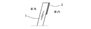
- FIG. 1 is a conceptual cross-sectional view showing a state in which a feeding terminal is joined to a predetermined location on a glass plate bus bar by the method of the present invention.
- a black ceramic layer 2 is disposed on the glass plate 1.
- the black ceramic paste is applied on the glass plate 1 and then dried. Further, a silver paste is applied and dried on the dried black ceramic paste. Furthermore, it is common that the black ceramic paste and the silver paste are simultaneously sintered and strengthened in a glass strengthening furnace.
- the lead-free solder alloy layer 4 applied in the first step and the lead-free solder alloy layer 5 applied in the second step coexist.
- the power supply terminal 6 is on the lead-free solder alloy layer 5 applied in the second step.
- the power supply terminal 6 is often made of brass, but the material is not limited. Although the general shape of the power supply terminal 6 is shown in FIG. 1, the shape of the power supply terminal is many and is not limited to this shape.
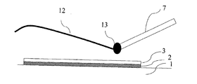
- FIG. 3 is a view showing a state in which a lead-free solder alloy 4 is heated and welded by a soldering iron (heater) 7 on a sintered body of silver paste placed on black ceramics in the first step.
- FIG. 3 is a view showing a state in which a lead-free solder alloy 4 is heated and welded by a soldering iron (heater) 7 on a sintered body of silver paste placed on black ceramics in the first step.
- FIG. 4 is a conceptual diagram of the present invention showing a state in which a power feeding terminal for an automobile window glass and an automobile window glass are joined in the fourth step.
- the lead-free solder alloy heat-welded in the first step and the second step heats both solder layers with a heater 9 or the like at a temperature not lower than the melting point and not higher than the melting point + 50 ° C. for not shorter than 3 seconds and not longer than 30 seconds.
- air is blown at a cooling rate of 5.0 ° C./sec or more to cool to room temperature.
- lead-free solder alloys are harder than leaded solder alloys and do not easily deform.
- Sn—Ag—Cu lead-free solder is not easily deformed because it is surrounded by a eutectic structure composed of an intermetallic compound of Ag 3 Sn and Cu 6 Sn 5 that is difficult to deform around the Sn crystal. .
- this eutectic structure cannot prevent the deformation and the deformation starts, the deformability until the breakage is low, and therefore, the eutectic structure is easily broken. Therefore, in order to stabilize the mechanical properties of the Sn—Ag—Cu lead-free solder, it is necessary to control the metal structure.
- the molten Sn—Ag—Cu lead-free solder is rapidly cooled to suppress the growth of Sn crystals, reduce the crystal size as much as possible, and quickly precipitate the eutectic structure. Due to the rapid cooling, the Sn crystal and the eutectic structure become a finely mixed metal structure, and the eutectic structure that prevents deformation is dispersed, so that the ability to prevent deformation is reduced, the deformation is easily deformed, and the deformability up to fracture is reduced. Due to the large structure, the mechanical properties can be stabilized.
- the cooling rate in the fifth step is preferably 5.0 ° C./sec or more. The more rapidly cooled, the finer the solder structure. When the cooling rate is smaller than this, the metal structure of the lead-free solder alloy is not stable, the toughness of the solder is lowered, and sufficient bonding strength cannot be obtained.
- the cooling rate is more preferably 6.0 ° C./sec or more. More preferably, it is 7.0 ° C./sec or more.
- the thickness of the lead-free solder alloy in the first step is 0.2 mm or more and 3 mm or less. If the thickness is less than 0.2 mm, a problem that good bonding strength cannot be obtained occurs. On the other hand, when it exceeds 3 mm, the problem which looks worse arises. More preferably, the thickness is 0.3 mm to 2 mm, and still more preferably 0.4 mm to 1.5 mm. In addition, about lead-free solder alloy, it does not necessarily become a uniform thickness in all, but since the area differs somewhat, it is better to interpret the above-mentioned value as an average value.
- the heat welding temperature of the lead-free solder alloy in the first step is not lower than the melting point and not higher than the melting point + 100 ° C. If the temperature is lower than the melting point, a problem that the lead-free solder alloy does not melt occurs. On the other hand, when the melting point exceeds + 100 ° C., fine cracks and the like are generated on the glass plate, and as a result, there is a problem that good bonding strength cannot be obtained. Furthermore, since time is required for cooling, the problem that production efficiency falls arises.
- it is melting
- the melting point is measured by a general differential thermal analyzer.
- the lead-free solder alloy is heat-welded in the first step using an ultrasonic soldering iron.
- an ultrasonic soldering iron By using an ultrasonic soldering iron, the bonding strength of the silver paste with the sintered body can be further increased.
- the application time of ultrasonic waves be 0.5 seconds or more and 20 seconds or less. If the time is less than 0.5 seconds, a problem that good bonding strength cannot be obtained occurs. On the other hand, if it exceeds 20 seconds, the characteristics of the sintered body of the silver paste change, and it may not be possible to join the lead-free solder alloy. More preferably, they are 1 second or more and 15 seconds or less, More preferably, they are 2 seconds or more and 10 seconds or less.
- the lead-free solder alloy in the second step has a thickness of 0.5 mm to 5 mm. If the thickness is less than 0.5 mm, a problem that good bonding strength cannot be obtained occurs. On the other hand, when it exceeds 5 mm, the problem which looks worse arises. More preferably, it is 0.8 mm or more and 4 mm or less, More preferably, it is 1 mm or more and 3 mm or less.
- the relative positions of the two solder layers are aligned and fixed using a positioning jig or the like.
- the bonding temperature in the fourth step is not less than the melting point and not more than the melting point + 50 ° C. If the temperature is lower than the melting point, a problem that the lead-free solder alloy does not melt occurs. On the other hand, when the melting point exceeds + 50 ° C., fine cracks and the like are generated on the glass plate. In addition, it takes time to cool the lead-free solder alloy, and the eutectic structure that prevents deformation of the lead-free solder alloy is not dispersed, so the deformation prevention ability is improved, the structure is difficult to deform, and the deformability until breakage is reduced. By doing so, the mechanical properties become unstable, resulting in a problem that good bonding strength cannot be obtained.
- the melting point is not lower than the melting point and not higher than the melting point + 40 ° C., and further preferably not lower than the melting point and not higher than the melting point + 30 ° C.
- the soldering is performed in advance on the terminal seat of the power supply terminal and the predetermined position on the conductive wire of the window glass of the automobile. For this reason, heat is easily transmitted to the solder, and even if the heating temperature is lowered, the bonding strength is exhibited. For example, a predetermined adhesive strength can be obtained even at a temperature of melting point + 30 ° C. or lower.
- the window glass for automobile has a black ceramic layer and a sintered body of silver paste is heat-welded on the black ceramic layer.
- the window glass for automobiles having a black ceramic layer has a higher temperature in a portion where the black ceramic paste is applied in a heating process during processing than in other portions. Therefore, when the sintered body of the silver paste is present on the black ceramic layer, the silver paste is overfired more than usual during the sintering, and the adhesive strength with the power supply terminal tends to be small.
- solder alloy there is an In—Ag—Sn solder. Further, the desirable composition thereof will be described below. In-Ag—Sn solder composed of 26% by weight to 56% by weight In, 0.1% by weight to 5% by weight Ag, and the balance of Sn. . If In is less than 26% by weight, the Young's modulus increases, and the glass plate may be cracked. On the other hand, if In exceeds 56% by weight, the adhesive strength of the lead-free solder alloy is reduced due to residual internal stress due to the phase change of In 3 Sn / In 3 Sn + InSn 4 and the occurrence of cracks even at a temperature change near room temperature. More preferably, it is 28 to 54 weight%.
- the amount of Ag added in the present invention is preferably 0.1% by mass or more and 5% by mass or less.
- a defogger heat wire and an antenna wire are formed by screen printing-drying-firing silver paste, and a power supply terminal that contacts the silver wire and the vehicle body is connected by a lead-free solder alloy.
- a lead-free solder alloy In order to prevent silver wire corrosion (so-called silver erosion) by the lead-free solder alloy, it is effective to add Ag to the lead-free solder alloy.
- these effects are low, and if it exceeds 5% by mass, coarse Ag 3 Sn precipitates, which causes a decrease in strength and fatigue strength.
- they are 0.5 weight% or more and 3 weight% or less, More preferably, they are 0.8 weight% or more and 2 weight% or less.
- the melting point is preferably 90 ° C. or higher and 200 ° C. or lower.
- a lead-free solder alloy of less than 90 ° C. cannot be easily obtained.
- it exceeds 200 ° C. there arises a problem that the bonding strength is lowered. More preferably, it is 95 degreeC or more and 180 degrees C or less, More preferably, it is 100 degreeC or more and 160 degrees C or less. However, it is not necessarily limited to these conditions.
- Sn-Ag-Cu solder is another desirable lead-free solder alloy. Further, the desirable composition thereof will be described below. Sn—Ag composed of 94 wt% to 97 wt% Sn, 2 wt% to 5 wt% Ag, and 0.5 wt% to 2 wt% Cu. -Cu solder.
- Sn is less than 94% by weight, there arises a problem that basic characteristics as a lead-free solder alloy are deteriorated.
- it exceeds 97% by weight there arises a problem that the bonding strength becomes weak. More preferably, they are 94.5 weight% or more and 96.5 weight% or less.
- the lead-free solder alloy becomes hard and brittle, which causes a problem that the bonding strength is lowered. More preferably, they are 0.7 weight% or more and 1.8 weight% or less, More preferably, they are 0.8 weight% or more and 1.7 weight% or less.
- the melting point of Sn—Ag—Cu solder is almost limited to 210 ° C. or higher and 230 ° C. or lower.
- the cold cycle test the salt spray test
- the adhesive strength test refer to the following tests. The details will be described below.
- Salt spray test A salt spray test according to JIS Z2371 was conducted. That is, a 5% NaCl aqueous solution was continuously sprayed at a spraying pressure of 0.1 MPa for 100 hours in an atmosphere at 35 ° C., and the bonding strength after the test was measured.
- Bonding strength test This was performed according to JIS C60068. Bonding strength is measured by bending the connecting part of the power supply terminal so that it is perpendicular to the terminal seat and pulling the connecting part in a direction perpendicular to the joint surface using a push-pull gauge. Those that did not peel off were determined to have good adhesive strength.
- Example 1 First, after applying a black ceramic paste comprising a low melting point glass frit mainly composed of Bi-based borosilicate glass, a black inorganic pigment, an inorganic filler, and a solvent mainly composed of pine oil to a glass plate sample, it is once dried, On top of that, a silver paste composed of a fine melting point of silver particles, a low melting point glass frit mainly composed of Bi-based borosilicate glass, and a solvent mainly composed of terpineol is applied, and after drying, heated to 700 ° C. in a glass strengthening furnace. Then, the paste was fired and the glass plate was tempered simultaneously by rapid cooling. In this way, a tempered glass plate sample similar to a commercially available automobile window glass provided with a sintered body of silver paste was prepared.
- a black ceramic paste comprising a low melting point glass frit mainly composed of Bi-based borosilicate glass, a black inorganic pigment, an inorganic filler, and a solvent mainly
- a general flux was thinly spread on the sintered body of silver paste. Thereafter, about 0.3 g (weight per one place) of a lead-free solder alloy having a diameter of 1.6 mm manufactured in a thread shape was melted and thickened to a thickness of about 1.5 mm on the sintered body of the silver paste.
- the thread-shaped lead-free solder alloy 12 is a lead-free solder alloy 13 in a molten state at the tip of the soldering iron 7.
- the composition of the lead-free solder alloy used here was 51% by weight of In, 1% by weight of Ag, 48% by weight of Sn, and its melting point was 115 ° C.
- the melting point was measured according to JIS Z3198-1, and was measured using a differential type differential thermal balance TG8120 manufactured by Rigaku Corporation. Further, the lead-free solder alloy was heated for about 5 seconds on the sintered body of the silver paste, and was deposited on the sintered body of the silver paste. The temperature of the soldering iron was adjusted so that the lead-free solder alloy temperature was a predetermined temperature.
- the terminals and the glass plate are fixed with clips by aligning the positions of the respective solder layers heated and welded in the first step and the second step, and as a fourth step, the temperature of the lead-free solder alloy is about 140. 4.
- Heater (Stainnel Co., Ltd.) adjusted to 0 ° C. is applied for 8 seconds to heat both solder layers and weld and bond the two solder layers, and then, as a fifth step, air is blown. It cooled to 30 degreeC with the cooling rate of 0 degreeC / sec.
- the temperature of the lead-free solder alloy at this time was measured using a data logger AM-7012L manufactured by Anritsu Keiki Co., Ltd., with a thermocouple installed in the vicinity of the lead-free solder alloy.
- the initial bonding strength of the five power supply terminals bonded in this way was measured. As a result, it was confirmed that all values exceeding 80N required in the market were exceeded.
- Example 2 A tempered glass plate sample almost the same as in Example 1 was prepared. As a first step, a general flux was thinly spread on the sintered body of the silver paste. Thereafter, about 0.03 g (weight per one place) of a lead-free solder alloy having a diameter of 1.6 mm produced in a thread shape was melted and deposited on the silver paste sintered body to a thickness of about 0.4 mm.
- the composition of the lead-free solder alloy used here is 95.2% by weight of Sn, 3.8% by weight of Ag, 1% by weight of Cu, and its melting point is 215 ° C.
- the total amount of lead-free solder alloy in the first step and the second step is about 0.23 g per location, and the ratio of the amount of lead-free solder alloy in the first step to the amount of lead-free solder alloy in the second step is about It was 0.2.
- the terminals and the glass plate are fixed with clips by aligning the positions of the solder layers heated and welded in the first step and the second step, and in the fourth step, the lead-free solder alloy temperature is about 230 ° C.
- the solder layers made by Steinel
- air was blown to 5.0 It cooled to 30 degreeC with the cooling rate of (degreeC) / sec.
- the temperature of the lead-free solder alloy at this time was measured using a data logger AM-7012L manufactured by Anritsu Keiki Co., Ltd., with a thermocouple installed in the vicinity of the lead-free solder alloy.
- the initial bonding strength of the five power supply terminals bonded in this way was measured. As a result, it was confirmed that it exceeded all 80N values required in the market.
- Example 3 A tempered glass plate sample almost the same as in Example 1 was prepared.
- a general flux was thinly spread on the sintered body of the silver paste.
- an ultrasonic soldering iron manufactured by Eishin Kogyo Co., Ltd., melt about 0.3 g of lead-free solder alloy with a diameter of 1.6 mm (weight per part) on the silver paste sintered body while melting it. The height was about 1.5 mm.
- ultrasonic waves were oscillated for about 2 seconds.
- the composition of the lead-free solder alloy used here was 51% by weight of In, 1% by weight of Ag, 48% by weight of Sn, and its melting point was 115 ° C.
- the initial bonding strength of the five power supply terminals bonded in this way was measured. As a result, it was confirmed that it exceeded all 80N values required in the market.
- Example 1 A glass plate sample produced under substantially the same conditions as in Example 1 was prepared.
- a lead-free solder alloy having the same composition as in Example 1 was used. Further, the same soldering iron as in Example 1 was used. Moreover, it performed by what is called the conventional method of performing only by Step 2 without dividing Step 1 and Step 2. At this time, the amount of the lead-free solder alloy was about 0.55 g per one place.
- Other conditions were the same as in Example 1.
- the initial bonding strength of the five power supply terminals bonded in this way was measured. As a result, it was confirmed that it exceeded all 80N values required in the market.
- Example 2 A glass plate sample produced under substantially the same conditions as in Example 2 was prepared.
- the lead-free solder alloy a lead-free solder alloy having the same composition as in Example 2 was used. Moreover, it performed by what is called the conventional method of performing only by Step 2 without dividing Step 1 and Step 2. At this time, the amount of the lead-free solder alloy was about 0.43 g per one place. Other conditions were the same as in Example 2.
- the initial bonding strength of the five power supply terminals bonded in this way was measured. As a result, one sample out of five samples was less than 80N with respect to 80N which is a value required in the market.
- Examples 1, 2, and 3 of the present invention were all good, with bonding strengths exceeding 80 N immediately after soldering, after the thermal cycle test and after the salt spray test.
- Comparative Examples 1 and 2 soldered only in Step 2 without separating Step 1 and Step 2, there is a sample whose adhesive strength immediately after soldering, after the thermal cycle test and after the salt spray test is less than 80N. It was not good.
Abstract
Disclosed is a method that is for joining an automobile window glass to an electricity supply terminal and that contains: a first step wherein, using a lead-free solder alloy, a solder layer is formed by heat welding to a predetermined location on a conductive wire formed on the surface of the automobile window glass; a second step for forming a solder layer by heat welding to the terminal seat of the electricity supply terminal; a third step for positioning the surface of the solder layer formed in the second step to the solder layer formed in the first step; a fourth step for further heating both solder layers using a heater having a controlled heating temperature, thus welding and joining both solder layers together; and a fifth step for cooling by controlling the cooling temperature.
Description
本発明は、自動車用窓ガラスに給電端子と呼ばれる金属製端子を接合する方法に関するものである。
The present invention relates to a method of joining a metal terminal called a power feeding terminal to an automobile window glass.
近年、車両用の窓ガラスを利用して種々の特性を付与する試みがなされている。例えば、デフォッガと呼ばれる防曇素子やガラスアンテナがある。デフォッガは、ガラス板のほぼ全面にわたって横向きかつ平行に配設された複数本の抵抗発熱線と、この抵抗発熱線の端部に給電するための2本のバスバと呼ばれる導電線で構成されている。2本のバスバは、ガラス板の左右両側に対向して配設され、抵抗発熱線に充分な電力を供給すべく、抵抗発熱線よりも太い配線幅を有する。バスバ間には電流が流され、それにより抵抗発熱線が発熱してガラス板を温め、結露による視界不良を防ぐことができる。
In recent years, attempts have been made to impart various characteristics using vehicle window glass. For example, there is an antifogging element called a defogger or a glass antenna. The defogger is composed of a plurality of resistance heating wires disposed horizontally and in parallel over almost the entire surface of the glass plate, and two conductive wires called bus bars for supplying power to the ends of the resistance heating wires. . The two bus bars are arranged opposite to the left and right sides of the glass plate, and have a wiring width wider than that of the resistance heating line in order to supply sufficient power to the resistance heating line. An electric current is passed between the bus bars, whereby the resistance heating wire generates heat and warms the glass plate, thereby preventing poor visibility due to condensation.
このようなバスバは、ガラスフリット、銀粒子及び有機バインダで構成される銀ペーストをガラス板にスクリーン印刷してから、それを乾燥、焼成することで作られる。
Such a bus bar is made by screen-printing a silver paste composed of glass frit, silver particles and an organic binder on a glass plate, and then drying and baking it.
電流は、デフォッガでは、該バスバ上の所定箇所にハンダ付けされた給電端子から供給される。また、ガラスアンテナでは、該給電端子から電流が取り出される。
In the defogger, the current is supplied from a power supply terminal soldered to a predetermined location on the bus bar. In the glass antenna, current is taken out from the power supply terminal.
従来は、給電端子とバスバとの間は鉛を含むハンダによって接続されていた。しかし、鉛は毒性の強い環境汚染物質であり、健康への悪影響の他、環境特に生態系への悪影響や汚染が問題視されている。そのため、鉛を極力使用しないよう、社会的に強い要請がある。家電業界を始め多くの業界では、種々のハンダ付用途に低鉛又は無鉛のハンダを既に使用している。このような動きは、車両用のハンダに対しても同様であり、車両用のハンダを無鉛化する動きは急速に広まっている。
Conventionally, the power supply terminal and the bus bar are connected by solder containing lead. However, lead is a highly toxic environmental pollutant. In addition to adverse effects on health, adverse effects and pollution on the environment, especially the ecosystem, are regarded as problems. Therefore, there is a strong social demand not to use lead as much as possible. Many industries, including the consumer electronics industry, have already used low-lead or lead-free solder for various soldering applications. Such a movement is similar to the solder for the vehicle, and the movement to make the solder for the vehicle lead-free is rapidly spreading.
しかし、車両用ガラス板の用途において、低鉛又は無鉛のハンダで従来から要求されている特性を満足させることは非常に難しい。これは、主に家電製品が室内で使われるのに対し、車両用ガラス板は屋外で使われるため、劣悪な環境にも耐えなければならないことがその主な理由としてあげられる。また、安全性の問題も極めて重要であり、それも含めて要求されるため、過酷な試験に合格するものでなければならないためである。このため、例えば冷熱サイクル試験や塩水噴霧試験に合格することが客先から要求されているが、簡単に合格できるものではない。
However, it is very difficult to satisfy the characteristics conventionally required with low-lead or lead-free solder in the use of glass plates for vehicles. This is mainly because household appliances are used indoors, whereas glass plates for vehicles are used outdoors, so they must endure a poor environment. In addition, safety issues are extremely important, and are required to pass, so they must pass a severe test. For this reason, for example, the customer is required to pass a cooling / heating cycle test or a salt spray test, but it cannot be easily passed.
さらには、防眩性能を高めるため、あるいは熱線用端子等が外部から見えないようにする隠蔽機能等を目的として、黒色又はそれに近い色調のセラミックス(以下、黒色状セラミックス)不透明層がガラス板の周辺部等に塗布し焼き付けされたガラス板も数多く市場に出回っている。このようなガラス板は、該黒色状セラミックス層上にバスバが設けられることが多いため、給電端子とバスバを接続するために使用するハンダについては、バスバだけでなく、黒色状セラミックス層に対する特性も加味されなければならないという事情もある。図7及び図8にガラス板の周辺部に黒色状セラミックス層を塗布、乾燥し焼き付けたガラス板の一例を示す。黒色セラミックス層はガラスフリットと顔料からなるペーストをスクリーン印刷でガラス板表面へ所定の形状に印刷し、乾燥後、600℃~700℃で焼成して、黒色状セラミックスがガラス板に強固に付着した状態で形成される。
Furthermore, for the purpose of enhancing the antiglare performance, or for the purpose of concealing the heat ray terminals and the like from the outside, a ceramic having a black or near-tone color (hereinafter referred to as a black ceramic) opaque layer is formed on the glass plate. There are many glass plates on the market that are coated and baked on the periphery. Since such a glass plate is often provided with a bus bar on the black ceramic layer, the solder used to connect the power supply terminal and the bus bar has characteristics not only for the bus bar but also for the black ceramic layer. There are also circumstances that must be taken into account. 7 and 8 show an example of a glass plate in which a black ceramic layer is applied to the periphery of the glass plate, dried and baked. For the black ceramic layer, a paste made of glass frit and pigment is printed on the surface of the glass plate by screen printing in a predetermined shape, dried and fired at 600 ° C. to 700 ° C., and the black ceramic layer adheres firmly to the glass plate. Formed in a state.
特許文献1,2には、有害物質の鉛を含まず、ガラス、セラミックス等の酸化物材料に対して十分な接合強度を有する無鉛ハンダが開示されている。
Patent Documents 1 and 2 disclose lead-free solders that do not contain lead, which is a harmful substance, and have sufficient bonding strength to oxide materials such as glass and ceramics.
また、特許文献3には、無鉛ハンダ合金でハンダ付した後のガラス板内の応力発生に着目した車両用ガラスパネルが開示されている。
Patent Document 3 discloses a vehicle glass panel that pays attention to generation of stress in a glass plate after soldering with a lead-free solder alloy.
また、特許文献4には、30部よりも大きい反応速度調整剤とともに、70部未満のSnで構成されるハンダを用いる車両の窓ガラス板用の電気コネクタが開示されている。
Further, Patent Document 4 discloses an electrical connector for a vehicle window glass plate using solder composed of less than 70 parts of Sn together with a reaction rate adjusting agent larger than 30 parts.
また、特許文献5には、無鉛ハンダの融点よりも100℃低い温度から10℃高い温度までの範囲に予熱した車両用窓ガラス板に、端子の接着部を加熱して無鉛ハンダにより車両用窓ガラス板の導電体に端子を接着するハンダ付け方法が開示されている。
Further, in Patent Document 5, a vehicle window glass plate preheated in a range from a temperature lower by 100 ° C. to a temperature higher by 10 ° C. than the melting point of lead-free solder is used to heat the bonding portion of the terminal and lead the vehicle window by lead-free solder. A soldering method for bonding a terminal to a conductor of a glass plate is disclosed.
さらに、特許文献6には、錫、インジウム、銀及びビスマスを含む無鉛ハンダの組成物と2種類のハンダを使った自動車ガラス板への接合方法及び装置が開示されている。
Furthermore, Patent Document 6 discloses a lead-free solder composition containing tin, indium, silver and bismuth and a method and apparatus for joining to an automotive glass plate using two types of solder.
従来の鉛ハンダによる接合では、自動車用窓ガラスの給電端子のみにハンダをつけて、銀ペーストの焼結体とフラックスを使いながら自動車用窓ガラスとその給電端子を接合してきた。この方法は、簡単であり、コストが安くすむというメリットもある。
In conventional joining with lead solder, soldering is applied only to the power supply terminal of the automobile window glass, and the automobile window glass and its power supply terminal are joined using a sintered body of silver paste and flux. This method is advantageous in that it is simple and low in cost.
近年、主に環境上の問題から無鉛ハンダ合金が使われるようになってきている。無鉛ハンダ合金も従来の方法とほぼ同様の給電端子のみにハンダをつける方法が検討されてきた。この方法ではハンダ内での割れはほとんど発生しないが、ハンダと銀ペーストの焼結体との界面あるいは銀ペーストの焼結体と黒色状セラミックスとの界面で割れが多発する傾向にあった。このような割れは、特に冷熱サイクル試験や塩水噴霧試験後において発生しやすい。このため、無鉛ハンダ合金の使用を客先から強く要求されてはいたが、種々の限定条件の中でしか対応することができなかった。特に、黒色状セラミックスが塗布された自動車用窓ガラスにおいては、この問題が顕著であった。
In recent years, lead-free solder alloys have been used mainly due to environmental problems. For lead-free solder alloys, a method for soldering only the power supply terminals, which is almost the same as the conventional method, has been studied. In this method, cracks in the solder hardly occur, but cracks tend to occur frequently at the interface between the solder and the sintered silver paste or the interface between the silver paste sintered and the black ceramic. Such cracks are likely to occur especially after a cold cycle test or a salt spray test. For this reason, the use of lead-free solder alloys has been strongly demanded by customers, but it has been able to cope only with various limited conditions. In particular, this problem is remarkable in the window glass for automobiles coated with black ceramics.
特許文献3に記載の物品では、機械的応力緩和成分が示されており、接合強度の増加につながると推察されるが、冷熱サイクル試験や塩水噴霧試験に対する特性を改善したものではない。
In the article described in Patent Document 3, a mechanical stress relaxation component is shown, and it is presumed that it leads to an increase in bonding strength, but it does not improve the characteristics for the cold cycle test and the salt spray test.
特許文献6に記載の組成物や方法では、2種類のハンダを使うという点では画期的ではあるが、冷熱サイクル試験や塩水噴霧試験に対する特性を改善したものではない。また、2種類のハンダでは、例えば上層のハンダは下層のハンダよりも低い溶融温度を有するとされており、その製造時の管理は難しいものがある。
The composition and method described in Patent Document 6 are epoch-making in that two types of solder are used, but they do not improve the characteristics for the cold cycle test and the salt spray test. Further, in the two types of solder, for example, the upper layer solder is said to have a lower melting temperature than the lower layer solder, and there are some which are difficult to manage during manufacture.
以上のように、従来技術では、無鉛ハンダ合金を用いた場合、給電端子の接合強度が十分ではなく、冷熱サイクルや塩水噴霧試験に合格することができなかった。このため、車両用ガラス板において、無鉛ハンダ合金を使うことには自ずと制限があった。本発明は、上記の問題点に鑑みてなされたものであり、特に黒色セラミックスが塗布された自動車用窓ガラスの場合でも、無鉛ハンダ合金による給電端子の接合強度を高めることを目的としている。
As described above, in the conventional technology, when lead-free solder alloy is used, the joining strength of the power feeding terminal is not sufficient, and the thermal cycle and the salt spray test cannot be passed. For this reason, in the glass plate for vehicles, there was a restriction | limiting naturally to using a lead-free solder alloy. The present invention has been made in view of the above-described problems, and an object of the present invention is to increase the bonding strength of a power supply terminal made of a lead-free solder alloy, particularly in the case of an automotive window glass coated with black ceramics.
本発明は、自動車用窓ガラスの表面に塗布して形成された銀ペーストの焼結体からなる導電線を介して窓ガラスと給電端子を無鉛ハンダ合金によりハンダ付けする方法において、
窓ガラスと給電端子のハンダ付けに用いる無鉛ハンダ合金を用いて、導電線上の所定箇所に加熱溶着させてハンダ層を形成する第1ステップ、
給電端子の端子座に加熱溶着させてハンダ層を形成する第2ステップ、
第1ステップで形成したハンダ層と第2ステップで形成したハンダ層の表面を位置合わせする第3ステップ、
加熱温度を制御したヒーターで両ハンダ層を加熱し両ハンダ層同士を溶着して接合させる第4ステップ、
冷却速度を制御して冷却する第5ステップからなることを特徴とする自動車用窓ガラスと給電端子の接合方法(第1方法)である。 The present invention is a method for soldering a window glass and a power supply terminal with a lead-free solder alloy through a conductive wire made of a sintered body of a silver paste formed by coating on the surface of an automotive window glass,
A first step of forming a solder layer by heat-welding to a predetermined location on a conductive wire using a lead-free solder alloy used for soldering a window glass and a power supply terminal;
A second step of forming a solder layer by heat-welding to the terminal seat of the power supply terminal;
A third step of aligning the solder layer formed in the first step and the surface of the solder layer formed in the second step;
A fourth step in which both solder layers are heated with a heater with a controlled heating temperature, and both solder layers are welded together and joined together;
This is a method (first method) for joining an automotive window glass and a power supply terminal, characterized by comprising a fifth step of cooling by controlling the cooling rate.
第1方法は、第1ステップにおけるハンダ層の厚さが、0.2mm以上3mm以下である、自動車用窓ガラスとその給電端子の接合方法(第2方法)であってもよい。
The first method may be a method of joining the window glass for an automobile and its power supply terminal (second method) in which the thickness of the solder layer in the first step is 0.2 mm or more and 3 mm or less.
第1又は第2方法は、第1ステップにおける無鉛ハンダ合金の加熱溶着温度が、融点以上、融点+100℃以下である、自動車用窓ガラスとその給電端子の接合方法(第3方法)であってもよい。
The first or second method is a joining method (third method) of an automotive window glass and its power supply terminal, wherein the heat welding temperature of the lead-free solder alloy in the first step is not lower than the melting point and not higher than the melting point + 100 ° C. Also good.
第1乃至第3方法のいずれか1つは、第1ステップにおける無鉛ハンダ合金の加熱溶着が、超音波を用いてなされる、自動車用窓ガラスとその給電端子の接合方法(第4方法)であってもよい。
Any one of the first to third methods is a joining method (fourth method) of an automotive window glass and its power supply terminal, in which the lead-free solder alloy is heat-welded in the first step using ultrasonic waves. There may be.
第1乃至第4方法のいずれか1つは、第2ステップにおけるハンダ層の厚さが、0.5mm以上5mm以下の厚さである、自動車用窓ガラスとその給電端子の接合方法(第5方法)であってもよい。
Any one of the first to fourth methods is a method of joining an automotive window glass and its power supply terminal (fifth), wherein the thickness of the solder layer in the second step is not less than 0.5 mm and not more than 5 mm. Method).
第1乃至第4方法のいずれか1つは、第4ステップにおける接合温度が、融点以上、融点+100℃以下である、自動車用窓ガラスとその給電端子の接合方法(第6方法)であってもよい。
Any one of the first to fourth methods is a joining method (sixth method) of an automotive window glass and its power feeding terminal, wherein the joining temperature in the fourth step is not lower than the melting point and not higher than the melting point + 100 ° C. Also good.
第1乃至第6方法のいずれか1つは、第5ステップにおける接合後の冷却速度の制御は、空気を吹き付けることにより、5.0℃/sec以上の冷却速度で制御して冷却する、自動車用窓ガラスとその給電端子の接合方法(第7方法)であってもよい。
In any one of the first to sixth methods, the cooling rate after joining in the fifth step is controlled by cooling at a cooling rate of 5.0 ° C./sec or more by blowing air, The window glass and its power feeding terminal joining method (seventh method) may be used.
第1乃至第7方法のいずれか1つは、自動車用窓ガラスが黒色状セラミックス層を有し、その黒色状セラミックス層の上に銀ペーストの焼結体が加熱溶着されている、自動車用窓ガラスとその給電端子の接合方法(第8方法)であってもよい。
Any one of the first to seventh methods includes: an automotive window glass having a black ceramic layer, and a sintered body of silver paste is heat-welded on the black ceramic layer. A joining method (eighth method) of glass and its power supply terminal may be used.
第1乃至第8方法のいずれか1つは、無鉛ハンダ合金がIn-Ag-Sn系ハンダである、自動車用窓ガラスとその給電端子の接合方法(第9方法)であってもよい。
Any one of the first to eighth methods may be a method for joining an automotive window glass and its power supply terminal (the ninth method) in which the lead-free solder alloy is In-Ag-Sn solder.
第1乃至第8方法のいずれか1つは、無鉛ハンダ合金がSn-Ag-Cu系ハンダである、自動車用窓ガラスとその給電端子の接合方法(第10方法)であってもよい。
Any one of the first to eighth methods may be a method of joining an automotive window glass and its power supply terminal (tenth method), in which the lead-free solder alloy is Sn—Ag—Cu solder.
本発明では、銀ペーストの焼結体の上に予め窓ガラスと給電端子と接合するために用いる無鉛ハンダ合金の一部を付着させ、該無鉛ハンダ合金を該銀ペーストの焼結体に加熱溶着することに特徴がある。この第1ステップの加熱溶着を行うことにより、該銀ペーストの焼結体を介するガラス板との界面反応によりハンダとガラス板表面との間に大きな接合強度を得ることができる。
In the present invention, a part of the lead-free solder alloy used for joining the window glass and the power supply terminal is previously deposited on the silver paste sintered body, and the lead-free solder alloy is heat-welded to the silver paste sintered body. There is a feature in doing. By performing the heat welding in the first step, a large bonding strength can be obtained between the solder and the glass plate surface by an interface reaction with the glass plate through the sintered body of the silver paste.
次に第2ステップとして、自動車用窓ガラス用の給電端子にも前記無鉛ハンダ合金の一部を用いて加熱溶着する。この第2ステップの加熱溶着を行うことにより、ハンダと給電端子の金属材料表面との間に大きな接合強度を得ることができる。
Next, as a second step, heat-welding is also performed on a power supply terminal for an automobile window glass using a part of the lead-free solder alloy. By performing the heat welding in the second step, a large bonding strength can be obtained between the solder and the metal material surface of the power supply terminal.
このように別々に予めハンダ層を形成した給電端子と窓ガラス双方のハンダ層表面を第3ステップで位置合わせして、第4ステップで両ハンダ層を加熱し両ハンダ層どうしを溶着して接合させる。この第4ステップは、両ハンダ層を加熱し両ハンダ層どうしを溶着して接合させるだけでよく、両ハンダ層の表面を溶着すれば十分な接着強度が得られるので、ヒーターによる加熱条件(温度、時間)を制御して、第1ステップで加熱溶着した窓ガラスとハンダ層の界面、第2ステップで加熱溶着した給電端子とハンダ層の界面部は再溶融することなく接合強度が維持される。
In this way, the solder layer surfaces of both the power supply terminal and the window glass, on which the solder layer is separately formed in advance, are aligned in the third step, and both the solder layers are heated and welded together in the fourth step. Let In this fourth step, it is only necessary to heat both solder layers and weld and bond the two solder layers, and if the surfaces of both solder layers are welded, sufficient adhesive strength can be obtained. ), The bonding strength is maintained without remelting the interface between the window glass and the solder layer heat-welded in the first step and the interface between the power supply terminal and the solder layer heat-welded in the second step. .
なお、第1ステップと第2ステップの順序は限定されない。また、第1ステップと第2ステップで用いるハンダ合金の組成は同一のものが望ましい。すなわち、2種類の無鉛ハンダ合金を融合させてハンダどうしを接着させるのではなく、同じ無鉛ハンダ合金を使って接合させればよい。組成が大きく異なる2種類の無鉛ハンダ合金をうまく融合させるのはかなり難しく、2種類の無鉛ハンダ合金の間に界面が発生することがある。このような界面が発生すると、その界面上で熱収縮の問題が発生したり、塩水が入り込んだりする。したがって、このような界面が生じて接合強度を低下させることがないような合金組成であれば、第1ステップと第2ステップで用いるハンダ組成が多少異なったり改良成分が添加されたりしていてもよい。
Note that the order of the first step and the second step is not limited. Further, it is desirable that the solder alloys used in the first step and the second step have the same composition. That is, two types of lead-free solder alloys are not fused to bond the solders together, but may be joined using the same lead-free solder alloy. It is quite difficult to successfully fuse two types of lead-free solder alloys having very different compositions, and an interface may occur between the two types of lead-free solder alloys. When such an interface occurs, a problem of heat shrinkage occurs on the interface, or salt water enters. Therefore, if the alloy composition does not cause such an interface to reduce the bonding strength, the solder composition used in the first step and the second step may be slightly different or an improved component may be added. Good.
接合強度は、JIS C60068に準じて測定した。冷熱サイクル試験、塩水噴霧試験後の給電端子の連結部分を端子座と垂直になるように折り曲げ、その連結部分をプッシュ・プルゲージを用い、接合面に対して垂直方向に引っ張ることにより測定し、80Nのとき、給電端子が剥がれないものを、接着強度良と判定した。
The bonding strength was measured according to JIS C60068. Measured by bending the connection part of the power supply terminal after the thermal cycle test and salt spray test so as to be perpendicular to the terminal seat, and pulling the connection part in a direction perpendicular to the joint surface using a push-pull gauge. When the power supply terminal was not peeled off, it was determined that the adhesive strength was good.
本発明によれば、自動車用窓ガラスと金属製物質、特に給電端子と呼ばれる金属製端子とを無鉛ハンダ合金を用いて接合する場合でも、接合強度を高めることができる。特に、無鉛ハンダ合金を用いて給電端子を接合させたガラスを、昼夜の寒暖差が大きい地域や海岸近辺などのハンダに対して過酷な環境で長期間保持した状況を再現する冷熱サイクル試験や塩水噴霧試験後でも、無鉛ハンダ合金による給電端子のガラスへの接合強度を十分に保つことができる。
According to the present invention, even when an automotive window glass and a metallic material, particularly a metallic terminal called a power feeding terminal are joined using a lead-free solder alloy, the joining strength can be increased. In particular, a thermal cycle test and salt water that reproduces the situation where glass with lead terminals joined using lead-free solder alloy is held for a long time in a harsh environment against solder in areas where the temperature difference between day and night is large or near the coast. Even after the spray test, the bonding strength of the power supply terminal to the glass with the lead-free solder alloy can be sufficiently maintained.
本発明の実施をするための形態を以下に述べる。
本発明は、自動車用窓ガラスの導電線と給電端子を無鉛ハンダ合金により接合させる方法に関する。導電線は、銀ペーストの焼結体で形成されている。第1ステップで、銀ペーストの焼結体上に無鉛ハンダ合金を加熱溶着しハンダ層を形成させる。第2ステップで、無鉛ハンダ合金を給電端子の端子座に加熱溶着しハンダ層を形成させる。第3ステップで、第1ステップで形成したハンダ層と第2ステップで形成したハンダ層の表面を位置合わせする。更に、第4ステップで、加熱温度を制御したヒーターで両ハンダ層を加熱し両ハンダ層同士を溶着して接合させる。第5ステップで、冷却速度を制御して急冷する。 A mode for carrying out the present invention will be described below.
The present invention relates to a method of joining a conductive wire of a window glass for an automobile and a feeding terminal with a lead-free solder alloy. The conductive wire is formed of a silver paste sintered body. In the first step, a lead-free solder alloy is heat-welded on the silver paste sintered body to form a solder layer. In the second step, a lead-free solder alloy is heat-welded to the terminal seat of the power supply terminal to form a solder layer. In the third step, the solder layer formed in the first step and the surface of the solder layer formed in the second step are aligned. Further, in the fourth step, both the solder layers are heated by a heater whose heating temperature is controlled, and both the solder layers are welded and bonded together. In the fifth step, the cooling rate is controlled to quench.
図2は、従来技術の方法によりガラス板のバスバ上の所定箇所に給電端子を接合した状態を示す断面概念図である。ガラス板1、黒色状セラミックス層2、銀ペーストの焼結体3と給電端子6の間はハンダ5で接合されている。また、給電端子6を大きくみると、外部の給電素子との連結部分10とガラス板と付着する給電端子座11から成り立っている。なお、給電端子座11は2つ座があるのが一般的であるが、1つの場合あるいは3つ以上の場合もある。
FIG. 2 is a conceptual cross-sectional view showing a state in which a power supply terminal is joined to a predetermined location on a glass bar bus bar by a conventional method. The glass plate 1, the black ceramic layer 2, the silver paste sintered body 3 and the power supply terminal 6 are joined by solder 5. Further, when the power supply terminal 6 is viewed in large size, the power supply terminal 6 includes a connection portion 10 with an external power supply element and a power supply terminal seat 11 attached to the glass plate. In general, the power supply terminal 11 has two seats, but there may be one or three or more.
図1は、本発明の方法によりガラス板のバスバ上の所定箇所に給電端子を接合した状態を示す断面概念図である。ガラス板1の上に黒色状セラミックス層2が配されている。黒色状セラミックスペーストはガラス板1上に塗布された後に乾燥される。さらに、乾燥された黒色状セラミックスペースト上に銀ペーストが塗布、乾燥される。さらに、ガラス強化炉で黒色状セラミックスペーストと銀ペーストの焼結と強化処理が同時になされるのが一般的である。
FIG. 1 is a conceptual cross-sectional view showing a state in which a feeding terminal is joined to a predetermined location on a glass plate bus bar by the method of the present invention. A black ceramic layer 2 is disposed on the glass plate 1. The black ceramic paste is applied on the glass plate 1 and then dried. Further, a silver paste is applied and dried on the dried black ceramic paste. Furthermore, it is common that the black ceramic paste and the silver paste are simultaneously sintered and strengthened in a glass strengthening furnace.
銀ペーストの焼結体3の上には、第1ステップで付与された無鉛ハンダ合金層4と第2ステップで付与された無鉛ハンダ合金層5が共存している。さらに、第2ステップで付与された無鉛ハンダ合金層5の上には、給電端子6がある。この給電端子6は、黄銅製であることが多いが、その材質は問わない。なお、給電端子6の一般的な形状を図1に示したが、給電端子の形状は数多くあり、本形状に限定されるものではない。
On the silver paste sintered body 3, the lead-free solder alloy layer 4 applied in the first step and the lead-free solder alloy layer 5 applied in the second step coexist. Further, the power supply terminal 6 is on the lead-free solder alloy layer 5 applied in the second step. The power supply terminal 6 is often made of brass, but the material is not limited. Although the general shape of the power supply terminal 6 is shown in FIG. 1, the shape of the power supply terminal is many and is not limited to this shape.
図3は、第1ステップにおいて、黒色状セラミックスの上に置かれた銀ペーストの焼結体の上に無鉛ハンダ合金4をハンダごて(ヒーター)7で加熱溶着させている様子を示す本発明の概念図である。
FIG. 3 is a view showing a state in which a lead-free solder alloy 4 is heated and welded by a soldering iron (heater) 7 on a sintered body of silver paste placed on black ceramics in the first step. FIG.
図4は、第4ステップにおいて、自動車用窓ガラス用の給電端子と自動車用窓ガラスを接合させる様子を示す本発明の概念図である。第1ステップ及び第2ステップで加熱溶着された無鉛ハンダ合金は、ヒーター9等により、融点以上、融点+50℃以下の温度で、3秒以上、30秒以下で両ハンダ層を加熱し両ハンダ層同士を溶着して接合された後、5.0℃/sec以上の冷却速度で、空気を吹き付けて室温まで冷却される。
FIG. 4 is a conceptual diagram of the present invention showing a state in which a power feeding terminal for an automobile window glass and an automobile window glass are joined in the fourth step. The lead-free solder alloy heat-welded in the first step and the second step heats both solder layers with a heater 9 or the like at a temperature not lower than the melting point and not higher than the melting point + 50 ° C. for not shorter than 3 seconds and not longer than 30 seconds. After being welded and joined together, air is blown at a cooling rate of 5.0 ° C./sec or more to cool to room temperature.
一般的に、無鉛ハンダ合金は、有鉛ハンダ合金と比較し、硬く、容易に変形しない。例えば、Sn-Ag-Cu系の無鉛ハンダは、Snの結晶の周りを変形し難いAg3SnとCu6Sn5という金属間化合物からなる共晶組織で囲まれているため、容易に変形しない。しかし、この共晶組織が変形を阻止できなくなり変形が始まると、破断までの変形能が低いことから、容易に破断に至るという特徴を持っている。そこで、Sn-Ag-Cu系の無鉛ハンダの機械的性質を安定にするには、金属組織を制御する必要がある。溶融したSn-Ag-Cu系の無鉛ハンダを急冷し、Snの結晶の成長を抑え、できる限り結晶サイズを小さくし、共晶組織を素早く析出させる。急冷により、Snの結晶と共晶組織が細かく混ざり合った金属組織となり、変形を阻止する共晶組織が分散されることから、変形阻止能力が低下し、変形し易く、破断までの変形能の大きな構造ができることにより、機械的性質を安定にすることができる。
Generally, lead-free solder alloys are harder than leaded solder alloys and do not easily deform. For example, Sn—Ag—Cu lead-free solder is not easily deformed because it is surrounded by a eutectic structure composed of an intermetallic compound of Ag 3 Sn and Cu 6 Sn 5 that is difficult to deform around the Sn crystal. . However, when this eutectic structure cannot prevent the deformation and the deformation starts, the deformability until the breakage is low, and therefore, the eutectic structure is easily broken. Therefore, in order to stabilize the mechanical properties of the Sn—Ag—Cu lead-free solder, it is necessary to control the metal structure. The molten Sn—Ag—Cu lead-free solder is rapidly cooled to suppress the growth of Sn crystals, reduce the crystal size as much as possible, and quickly precipitate the eutectic structure. Due to the rapid cooling, the Sn crystal and the eutectic structure become a finely mixed metal structure, and the eutectic structure that prevents deformation is dispersed, so that the ability to prevent deformation is reduced, the deformation is easily deformed, and the deformability up to fracture is reduced. Due to the large structure, the mechanical properties can be stabilized.
第5ステップでの冷却速度は、5.0℃/sec以上が好ましい。急冷する程ハンダの組織は微細化する。冷却速度が、これより小さいと無鉛ハンダ合金の金属組織が安定せず、ハンダの靱性が低くなり、十分な接合強度が得られない。冷却速度は、より好ましくは6.0℃/sec以上である。更に好ましくは7.0℃/sec以上である。
The cooling rate in the fifth step is preferably 5.0 ° C./sec or more. The more rapidly cooled, the finer the solder structure. When the cooling rate is smaller than this, the metal structure of the lead-free solder alloy is not stable, the toughness of the solder is lowered, and sufficient bonding strength cannot be obtained. The cooling rate is more preferably 6.0 ° C./sec or more. More preferably, it is 7.0 ° C./sec or more.
本発明においては、第1ステップにおける無鉛ハンダ合金の厚さが、0.2mm以上3mm以下であることが望ましい。0.2mm未満では、良好な接合強度が得られない問題が発生する。一方、3mmを超えた場合、見栄えが悪くなる問題が発生する。より好ましくは0.3mm以上2mm以下の厚さであり、さらに好ましくは0.4mm以上1.5mm以下の厚さである。なお、無鉛ハンダ合金については、全てのところで均一の厚さとなる訳ではなく、その面積も多少は異なるので、上述の値は平均値と解した方が良い。
In the present invention, it is desirable that the thickness of the lead-free solder alloy in the first step is 0.2 mm or more and 3 mm or less. If the thickness is less than 0.2 mm, a problem that good bonding strength cannot be obtained occurs. On the other hand, when it exceeds 3 mm, the problem which looks worse arises. More preferably, the thickness is 0.3 mm to 2 mm, and still more preferably 0.4 mm to 1.5 mm. In addition, about lead-free solder alloy, it does not necessarily become a uniform thickness in all, but since the area differs somewhat, it is better to interpret the above-mentioned value as an average value.
また、本発明においては、第1ステップにおける無鉛ハンダ合金の加熱溶着温度が、融点以上、融点+100℃以下であることが望ましい。融点よりも低い温度とすると、無鉛ハンダ合金が溶けない問題が発生する。一方、融点+100℃を超えると、ガラス板上に微細クラック等が発生し、結果として良好な接合強度が得られない問題が発生する。さらには、冷却に時間を要するため、生産効率が下がるという問題も発生する。より好ましくは、融点+10℃以上、融点+80℃以下であり、さらに好ましくは、融点+20℃以上、融点+50℃以下である。ここで、融点は、一般の示差熱分析装置により測定される。
In the present invention, it is desirable that the heat welding temperature of the lead-free solder alloy in the first step is not lower than the melting point and not higher than the melting point + 100 ° C. If the temperature is lower than the melting point, a problem that the lead-free solder alloy does not melt occurs. On the other hand, when the melting point exceeds + 100 ° C., fine cracks and the like are generated on the glass plate, and as a result, there is a problem that good bonding strength cannot be obtained. Furthermore, since time is required for cooling, the problem that production efficiency falls arises. More preferably, it is melting | fusing point +10 degreeC or more and melting | fusing point +80 degreeC or less, More preferably, it is melting | fusing point +20 degreeC or more and melting | fusing point +50 degreeC or less. Here, the melting point is measured by a general differential thermal analyzer.
また、本発明においては、図5に示すように、第1ステップにおける無鉛ハンダ合金の加熱溶着が、超音波ハンダごてを用いてなされることが望ましい。超音波ハンダごてを用いてなされることにより、さらに銀ペーストの焼結体との接合強度を高めることができる。なお、超音波付与の時間は、0.5秒以上20秒以下とすることが望ましい。0.5秒未満とすると、良好な接合強度を得られない問題が発生する。一方、20秒を越えると、銀ペーストの焼結体の特性が変化してしまい、無鉛ハンダ合金と接合できないことがある。より好ましくは1秒以上15秒以下であり、さらに好ましくは2秒以上10秒以下である。
Also, in the present invention, as shown in FIG. 5, it is desirable that the lead-free solder alloy is heat-welded in the first step using an ultrasonic soldering iron. By using an ultrasonic soldering iron, the bonding strength of the silver paste with the sintered body can be further increased. In addition, it is desirable that the application time of ultrasonic waves be 0.5 seconds or more and 20 seconds or less. If the time is less than 0.5 seconds, a problem that good bonding strength cannot be obtained occurs. On the other hand, if it exceeds 20 seconds, the characteristics of the sintered body of the silver paste change, and it may not be possible to join the lead-free solder alloy. More preferably, they are 1 second or more and 15 seconds or less, More preferably, they are 2 seconds or more and 10 seconds or less.
また、本発明においては、第2ステップにおける無鉛ハンダ合金の厚さが、0.5mm以上5mm以下の厚さであることが望ましい。0.5mm未満では、良好な接合強度が得られない問題が発生する。一方、5mmを超えた場合、見栄えが悪くなる問題が発生する。より好ましくは0.8mm以上4mm以下であり、さらに好ましくは1mm以上3mm以下である。
In the present invention, it is desirable that the lead-free solder alloy in the second step has a thickness of 0.5 mm to 5 mm. If the thickness is less than 0.5 mm, a problem that good bonding strength cannot be obtained occurs. On the other hand, when it exceeds 5 mm, the problem which looks worse arises. More preferably, it is 0.8 mm or more and 4 mm or less, More preferably, it is 1 mm or more and 3 mm or less.
また、本発明においては、第3ステップとして、位置決め治具などを用いて、両ハンダ層の相対位置を合わせて固定する。
In the present invention, as a third step, the relative positions of the two solder layers are aligned and fixed using a positioning jig or the like.
また、本発明においては、第4ステップにおける接合温度は、融点以上融点+50℃以下であることが望ましい。融点よりも低い温度とすると、無鉛ハンダ合金が溶けない問題が発生する。一方、融点+50℃を超えると、ガラス板上に微細クラック等が発生する。また、無鉛ハンダ合金の冷却に時間を要し、無鉛ハンダ合金の変形を阻止する共晶組織が分散されないため、変形阻止能力が向上し、変形し難く、破断までの変形能が小さくなる構造ができることにより、機械的性質を不安定にするため、結果として良好な接合強度が得られない問題が発生する。さらには、冷却に時間を要するため、生産効率が下がるという問題も発生する。より好ましくは、融点以上融点+40℃以下であり、さらに好ましくは、融点以上、融点+30℃以下である。本発明においては、給電端子と自動車用窓ガラスの導電線を接合する前に、該給電端子の端子座と該自動車用窓ガラスの導電線上の所定箇所に事前に分けてハンダ盛りをしているために、ハンダに熱が伝わりやすく、加熱温度を下げても接合強度が発現する。例えば、融点+30℃以下の温度でさえ所定の接着強度が得られる。
In the present invention, it is desirable that the bonding temperature in the fourth step is not less than the melting point and not more than the melting point + 50 ° C. If the temperature is lower than the melting point, a problem that the lead-free solder alloy does not melt occurs. On the other hand, when the melting point exceeds + 50 ° C., fine cracks and the like are generated on the glass plate. In addition, it takes time to cool the lead-free solder alloy, and the eutectic structure that prevents deformation of the lead-free solder alloy is not dispersed, so the deformation prevention ability is improved, the structure is difficult to deform, and the deformability until breakage is reduced. By doing so, the mechanical properties become unstable, resulting in a problem that good bonding strength cannot be obtained. Furthermore, since time is required for cooling, the problem that production efficiency falls arises. More preferably, the melting point is not lower than the melting point and not higher than the melting point + 40 ° C., and further preferably not lower than the melting point and not higher than the melting point + 30 ° C. In the present invention, before joining the power supply terminal and the conductive wire of the automobile window glass, the soldering is performed in advance on the terminal seat of the power supply terminal and the predetermined position on the conductive wire of the window glass of the automobile. For this reason, heat is easily transmitted to the solder, and even if the heating temperature is lowered, the bonding strength is exhibited. For example, a predetermined adhesive strength can be obtained even at a temperature of melting point + 30 ° C. or lower.
また、本発明においては、自動車用窓ガラスが黒色状セラミックス層を有し、その黒色状セラミックス層上に銀ペーストの焼結体が加熱溶着されている場合に特に有用である。従来、黒色状セラミックス層を有する自動車用窓ガラスは、加工時の加熱工程において、黒色状セラミックスペーストが塗布されている箇所の温度がそれ以外の箇所に比べて高くなる。したがって、銀ペーストの焼結体が黒色状セラミックス層上に存在する場合、焼結時において、通常よりも銀ペーストが過焼成となり、給電端子との接着強度は小さくなる傾向にあった。
Further, in the present invention, it is particularly useful when the window glass for automobile has a black ceramic layer and a sintered body of silver paste is heat-welded on the black ceramic layer. Conventionally, the window glass for automobiles having a black ceramic layer has a higher temperature in a portion where the black ceramic paste is applied in a heating process during processing than in other portions. Therefore, when the sintered body of the silver paste is present on the black ceramic layer, the silver paste is overfired more than usual during the sintering, and the adhesive strength with the power supply terminal tends to be small.
また、本発明においては、望ましい無鉛ハンダ合金として、In-Ag-Sn系ハンダがある。さらに、その望ましい組成を以下に述べると、26重量%以上56重量%以下のIn、0.1重量%以上5重量%以下のAg、及び残部のSnからなるIn-Ag-Sn系ハンダである。Inが26重量%未満ではヤング率が大きくなり、ガラス板にクラックを与える可能性がある。逆にInが56重量%を超えると、常温付近の温度変化においてもIn3Sn/In3Sn+InSn4の相変化による内部応力の残留や、クラック発生により、無鉛ハンダ合金の接着強度が低下する。より好ましくは28重量%以上54重量%以下である。さらに好ましくは31重量%以上51重量%以下である。本発明のAg添加量は0.1質量%以上5質量%以下が好ましい。Agを添加することにより、無鉛ハンダ合金の機械的強度の向上に優れた効果を発揮する。また車両用ガラス板では、銀ペーストをスクリーン印刷-乾燥-焼成することでデフォッガ熱線やアンテナ線を形成させるが、これらの銀線と車体の接点を取る給電端子は無鉛ハンダ合金によって接続される。このとき、無鉛ハンダ合金による銀線の腐食(いわゆる銀喰われ)を防止するため、無鉛ハンダ合金中にAgを添加することが効果的である。しかし、0.1質量%未満ではこれらの効果が低く、5質量%を超えると粗大なAg3Snが析出し、強度低下や疲労強度を低下させる原因となる。好ましくは0.5重量%以上3重量%以下であり、さらに好ましくは0.8重量%以上2重量%以下である。
In the present invention, as a preferable lead-free solder alloy, there is an In—Ag—Sn solder. Further, the desirable composition thereof will be described below. In-Ag—Sn solder composed of 26% by weight to 56% by weight In, 0.1% by weight to 5% by weight Ag, and the balance of Sn. . If In is less than 26% by weight, the Young's modulus increases, and the glass plate may be cracked. On the other hand, if In exceeds 56% by weight, the adhesive strength of the lead-free solder alloy is reduced due to residual internal stress due to the phase change of In 3 Sn / In 3 Sn + InSn 4 and the occurrence of cracks even at a temperature change near room temperature. More preferably, it is 28 to 54 weight%. More preferably, it is 31 to 51 weight%. The amount of Ag added in the present invention is preferably 0.1% by mass or more and 5% by mass or less. By adding Ag, an effect excellent in improving the mechanical strength of the lead-free solder alloy is exhibited. Further, in a glass plate for a vehicle, a defogger heat wire and an antenna wire are formed by screen printing-drying-firing silver paste, and a power supply terminal that contacts the silver wire and the vehicle body is connected by a lead-free solder alloy. At this time, in order to prevent silver wire corrosion (so-called silver erosion) by the lead-free solder alloy, it is effective to add Ag to the lead-free solder alloy. However, if it is less than 0.1% by mass, these effects are low, and if it exceeds 5% by mass, coarse Ag 3 Sn precipitates, which causes a decrease in strength and fatigue strength. Preferably they are 0.5 weight% or more and 3 weight% or less, More preferably, they are 0.8 weight% or more and 2 weight% or less.
また、融点としては、90℃以上200℃以下が望ましい。90℃未満の無鉛ハンダ合金を容易に得ることはできない。一方、200℃を越えると、接合強度が低下するという問題が発生する。より好ましくは95℃以上180℃以下であり、さらに好ましくは100℃以上160℃以下である。しかし、これらの条件に必ずしも限定される訳ではない。
Also, the melting point is preferably 90 ° C. or higher and 200 ° C. or lower. A lead-free solder alloy of less than 90 ° C. cannot be easily obtained. On the other hand, when it exceeds 200 ° C., there arises a problem that the bonding strength is lowered. More preferably, it is 95 degreeC or more and 180 degrees C or less, More preferably, it is 100 degreeC or more and 160 degrees C or less. However, it is not necessarily limited to these conditions.
さらに、本発明においては、もう1つの望ましい無鉛ハンダ合金として、Sn-Ag-Cu系ハンダがある。さらに、その望ましい組成を以下に述べると、94重量%以上97重量%以下のSn、2重量%以上5重量%以下のAg、0.5重量%以上2重量%以下のCuからなるSn-Ag-Cu系ハンダである。Snが94重量%未満では、無鉛ハンダ合金としての基本特性が低下する問題が発生する。一方、97重量%を越えると、接合強度が弱くなるという問題が発生する。より好ましくは94.5重量%以上96.5重量%以下である。また、Agが2重量%未満では、銀ペーストの焼結体との結合強度が弱くなるという問題が発生する。一方、5重量%を越えると、無鉛ハンダ合金表面に微細なクラックが発生し、機械的特性が下がるという問題が発生する。より好ましくは2.2重量%以上4.5重量%以下であり、さらに好ましくは2.5重量%以上3.8重量%以下である。また、Cuが0.5重量%未満では、Ag3Sn間金属間化合物の結合が弱くなり、接合強度が時間とともに低下するという問題が発生する。一方、2重量%を越えると、無鉛ハンダ合金が硬く脆くなるため、接合強度が低下するという問題が発生する。より好ましくは0.7重量%以上1.8重量%以下であり、さらに好ましくは0.8重量%以上1.7重量%以下である。
Furthermore, in the present invention, Sn-Ag-Cu solder is another desirable lead-free solder alloy. Further, the desirable composition thereof will be described below. Sn—Ag composed of 94 wt% to 97 wt% Sn, 2 wt% to 5 wt% Ag, and 0.5 wt% to 2 wt% Cu. -Cu solder. When Sn is less than 94% by weight, there arises a problem that basic characteristics as a lead-free solder alloy are deteriorated. On the other hand, if it exceeds 97% by weight, there arises a problem that the bonding strength becomes weak. More preferably, they are 94.5 weight% or more and 96.5 weight% or less. Further, when Ag is less than 2% by weight, there arises a problem that the bond strength between the silver paste and the sintered body is weakened. On the other hand, if it exceeds 5% by weight, there will be a problem that fine cracks are generated on the surface of the lead-free solder alloy and the mechanical properties are lowered. More preferably, it is 2.2 to 4.5 weight%, More preferably, it is 2.5 to 3.8 weight%. Further, if Cu is less than 0.5% by weight, the bond of the intermetallic compound between Ag 3 Sn becomes weak, and there arises a problem that the bonding strength decreases with time. On the other hand, if it exceeds 2% by weight, the lead-free solder alloy becomes hard and brittle, which causes a problem that the bonding strength is lowered. More preferably, they are 0.7 weight% or more and 1.8 weight% or less, More preferably, they are 0.8 weight% or more and 1.7 weight% or less.
また、Sn-Ag-Cu系ハンダの融点としては、210℃以上230℃以下にほぼ限定される。
Also, the melting point of Sn—Ag—Cu solder is almost limited to 210 ° C. or higher and 230 ° C. or lower.
以下、実施例により本発明を詳細に説明する。ここで、冷熱サイクル試験と塩水噴霧試験及び接着強度試験とは以下の試験をいう。以下、具体的に述べる。
Hereinafter, the present invention will be described in detail by way of examples. Here, the cold cycle test, the salt spray test, and the adhesive strength test refer to the following tests. The details will be described below.
[冷熱サイクル試験]
JIS C2807に準じた冷熱サイクル試験を行った。すなわち、20℃(3分)→-30℃(30分)→20℃(3分)→85℃(30分)→20℃(3分)を1サイクルとし、100サイクルを繰り返し実施した後の接合強度を測定した。なお、JIS C2807では、高温側温度が85℃と同じ温度であるが、低温側温度は-25℃であり、本実施例における試験よりは緩めとなっている。 [Cool cycle test]
A thermal cycle test according to JIS C2807 was performed. That is, 20 ° C. (3 minutes) → −30 ° C. (30 minutes) → 20 ° C. (3 minutes) → 85 ° C. (30 minutes) → 20 ° C. (3 minutes) The bonding strength was measured. In JIS C2807, the high temperature side temperature is the same as 85 ° C., but the low temperature side temperature is −25 ° C., which is more moderate than the test in this example.
[塩水噴霧試験]
JIS Z2371に準じた塩水噴霧試験を行った。すなわち、35℃の雰囲気中で5%のNaCl水溶液を噴霧圧0.1MPaにて100時間連続噴霧し、試験後の接合強度を測定した。 [Salt spray test]
A salt spray test according to JIS Z2371 was conducted. That is, a 5% NaCl aqueous solution was continuously sprayed at a spraying pressure of 0.1 MPa for 100 hours in an atmosphere at 35 ° C., and the bonding strength after the test was measured.
[接合強度試験]
JIS C60068に準じて行った。接合強度は、給電端子の連結部分を端子座と垂直になるように折り曲げ、その連結部分をプッシュ・プルゲージを用い、接合面に対して垂直方向に引っ張ることにより測定し、80Nのとき、給電端子が剥がれないものを、接着強度良と判定した。 [Joint strength test]
This was performed according to JIS C60068. Bonding strength is measured by bending the connecting part of the power supply terminal so that it is perpendicular to the terminal seat and pulling the connecting part in a direction perpendicular to the joint surface using a push-pull gauge. Those that did not peel off were determined to have good adhesive strength.
[実施例1]
先ず、Bi系硼珪酸ガラスを主成分とする低融点ガラスフリットと黒色無機顔料と無機フィラーとパインオイルを主成分とする溶媒からなる黒色状セラミックスペーストをガラス板試料に塗布した後に一度乾燥し、その上に、微細な銀粒子とBi系硼珪酸ガラスを主成分とする低融点ガラスフリットとテルピネオールを主成分とする溶媒からなる銀ペーストを塗布し、乾燥後に、ガラス強化炉で700℃に加熱した後、急冷することにより、ペーストの焼成とガラス板の強化処理を同時に行った。このようにして、銀ペーストの焼結体が施された市販されている自動車用窓ガラスと同様の強化ガラス板試料を準備した。 [Example 1]
First, after applying a black ceramic paste comprising a low melting point glass frit mainly composed of Bi-based borosilicate glass, a black inorganic pigment, an inorganic filler, and a solvent mainly composed of pine oil to a glass plate sample, it is once dried, On top of that, a silver paste composed of a fine melting point of silver particles, a low melting point glass frit mainly composed of Bi-based borosilicate glass, and a solvent mainly composed of terpineol is applied, and after drying, heated to 700 ° C. in a glass strengthening furnace. Then, the paste was fired and the glass plate was tempered simultaneously by rapid cooling. In this way, a tempered glass plate sample similar to a commercially available automobile window glass provided with a sintered body of silver paste was prepared.
第1ステップとして、銀ペーストの焼結体上に、一般的なフラックスを薄く塗り広げた。その後、糸状に製作した直径1.6mmの無鉛ハンダ合金約0.3g(1ヶ所あたりの重量)を溶かしながら銀ペーストの焼結体上に厚さが約1.5mmとなるように盛った。このとき、図6に示すように、糸状無鉛ハンダ合金12はハンダごて7の先端部で溶融状態の無鉛ハンダ合金13となっている。ここで用いた無鉛ハンダ合金の組成は、Inが51重量%、Agが1重量%、Snが48重量%であり、その融点は115℃であった。この融点の測定は、JIS Z3198-1に準じて行い、理学電機社製差動型示差熱天秤TG8120を用いて測定した。更に銀ペーストの焼結体上で、約5秒間無鉛ハンダ合金に熱をかけ、銀ペーストの焼結体上に溶着させた。無鉛ハンダ合金温度は、所定の温度となるよう、ハンダごて温度を調整した。
As a first step, a general flux was thinly spread on the sintered body of silver paste. Thereafter, about 0.3 g (weight per one place) of a lead-free solder alloy having a diameter of 1.6 mm manufactured in a thread shape was melted and thickened to a thickness of about 1.5 mm on the sintered body of the silver paste. At this time, as shown in FIG. 6, the thread-shaped lead-free solder alloy 12 is a lead-free solder alloy 13 in a molten state at the tip of the soldering iron 7. The composition of the lead-free solder alloy used here was 51% by weight of In, 1% by weight of Ag, 48% by weight of Sn, and its melting point was 115 ° C. The melting point was measured according to JIS Z3198-1, and was measured using a differential type differential thermal balance TG8120 manufactured by Rigaku Corporation. Further, the lead-free solder alloy was heated for about 5 seconds on the sintered body of the silver paste, and was deposited on the sintered body of the silver paste. The temperature of the soldering iron was adjusted so that the lead-free solder alloy temperature was a predetermined temperature.
次に、第2ステップとして、逆さにした、材質がJIS H 3100に規定されるC2801P(黄銅板)からなる給電端子の端子座面にフラックスを塗った。その後、ハンダごて前述の糸状無鉛ハンダ合金を1ヶ所あたり約0.4g溶かしながら、1端子当たり2ヶ所の座面に、厚さが約2mmとなるように、計0.8g盛った。従って、第1ステップと第2ステップの合計の無鉛ハンダ合金量は1ヶ所あたり約0.7gであり、第1ステップにおける無鉛ハンダ合金の量と第2ステップにおける無鉛ハンダ合金の量の比は約0.8であった。
Next, as a second step, flux was applied to the terminal seating surface of the power feeding terminal made of C2801P (brass plate) whose material was specified in JIS H3100 as inverted. Thereafter, while dissolving about 0.4 g of the above-mentioned thread-shaped lead-free solder alloy per soldering iron, 0.8 g in total was deposited on the two bearing surfaces per terminal so that the thickness was about 2 mm. Therefore, the total amount of lead-free solder alloy in the first step and the second step is about 0.7 g per location, and the ratio of the amount of lead-free solder alloy in the first step to the amount of lead-free solder alloy in the second step is about 0.8.
さらに、第3ステップとして、第1ステップと第2ステップで加熱溶着した各ハンダ層表面の位置を合わせて端子とガラス板をクリップで固定し、第4ステップとして、無鉛ハンダ合金の温度が約140℃になるよう調整したヒーター(ステインネル社製)を8秒間当てて両ハンダ層を加熱し両ハンダ層同士を溶着して接合を行った後、第5ステップとして、空気を吹きつけ、5.0℃/secの冷却速度で30℃まで冷却した。なお、このときの無鉛ハンダ合金の温度は、無鉛ハンダ合金の近傍に熱電対を設置し、安立計器社製データロガーAM-7012Lを用いて測定した。
Further, as a third step, the terminals and the glass plate are fixed with clips by aligning the positions of the respective solder layers heated and welded in the first step and the second step, and as a fourth step, the temperature of the lead-free solder alloy is about 140. 4. Heater (Stainnel Co., Ltd.) adjusted to 0 ° C. is applied for 8 seconds to heat both solder layers and weld and bond the two solder layers, and then, as a fifth step, air is blown. It cooled to 30 degreeC with the cooling rate of 0 degreeC / sec. The temperature of the lead-free solder alloy at this time was measured using a data logger AM-7012L manufactured by Anritsu Keiki Co., Ltd., with a thermocouple installed in the vicinity of the lead-free solder alloy.
このようにして接合した5つの給電端子の接合初期強度を測定した。その結果、市場で求められている値の80Nを全て超えていることを確認した。
The initial bonding strength of the five power supply terminals bonded in this way was measured. As a result, it was confirmed that all values exceeding 80N required in the market were exceeded.
その後、冷熱サイクル試験後(100サイクル)を実施し、その接合強度を調べたその結果は、市場で求められている値の80Nを全て超えていた。また、塩水噴霧試験後(100時間経過)の接合強度も実施した。その結果、市場で求められている値の80Nを全て超えていた。
Then, after the thermal cycle test (100 cycles), the results of examining the bonding strength exceeded all the values of 80N required in the market. Moreover, the joint strength after the salt spray test (after 100 hours) was also carried out. As a result, it exceeded all 80N values required in the market.
以上の結果、無鉛ハンダ合金を用いた場合でも、市場で求められている値の80Nを超えていることを確認した。
As a result of the above, it was confirmed that even when a lead-free solder alloy was used, it exceeded the value required in the market of 80N.
[実施例2]
実施例1とほぼ同様の強化ガラス板試料を準備した。第1ステップとして、銀ペーストの焼結体上に、一般的なフラックスを薄く塗り広げた。その後、糸状に製作した直径1.6mmの無鉛ハンダ合金約0.03g(1ヶ所あたりの重量)を溶かしながら銀ペーストの焼結体上に厚さが約0.4mmとなるように盛った。ここで用いた無鉛ハンダ合金の組成は、Snが95.2重量%、Agが3.8重量%、Cuが1重量%で、その融点は215℃である。 [Example 2]
A tempered glass plate sample almost the same as in Example 1 was prepared. As a first step, a general flux was thinly spread on the sintered body of the silver paste. Thereafter, about 0.03 g (weight per one place) of a lead-free solder alloy having a diameter of 1.6 mm produced in a thread shape was melted and deposited on the silver paste sintered body to a thickness of about 0.4 mm. The composition of the lead-free solder alloy used here is 95.2% by weight of Sn, 3.8% by weight of Ag, 1% by weight of Cu, and its melting point is 215 ° C.
次に、第2ステップとして、逆さにした給電端子の端子座面にフラックスを塗った。その後、ハンダごてで前述の糸無鉛ハンダ合金を溶かしながら、端子当たりの一つの座面に、厚さが約1mmとなるように、1ヶ所あたり約0.2gを盛った。従って、第1ステップと第2ステップの合計の無鉛ハンダ合金量は1ヶ所あたり約0.23gであり、第1ステップにおける無鉛ハンダ合金の量と第2ステップにおける無鉛ハンダ合金の量の比は約0.2であった。
Next, as a second step, flux was applied to the terminal seat surface of the inverted power feeding terminal. Thereafter, while melting the above-mentioned lead-free solder alloy with a soldering iron, about 0.2 g was deposited on one seating surface per terminal so that the thickness was about 1 mm. Accordingly, the total amount of lead-free solder alloy in the first step and the second step is about 0.23 g per location, and the ratio of the amount of lead-free solder alloy in the first step to the amount of lead-free solder alloy in the second step is about It was 0.2.
さらに、第3ステップとして、第1ステップと第2ステップで加熱溶着した各ハンダ層表面の位置を合わせて端子とガラス板をクリップで固定し、第4ステップとして、無鉛ハンダ合金温度が約230℃になるよう調整したヒーター(ステインネル社製)を22秒間当てて両ハンダ層を加熱し両ハンダ層同士を溶着して接合を行った後、第5ステップとして、空気を吹きつけ、5.0℃/secの冷却速度で30℃まで冷却した。なお、このときの無鉛ハンダ合金の温度は、無鉛ハンダ合金の近傍に熱電対を設置し、安立計器社製データロガーAM-7012Lを用いて測定した。
Further, as the third step, the terminals and the glass plate are fixed with clips by aligning the positions of the solder layers heated and welded in the first step and the second step, and in the fourth step, the lead-free solder alloy temperature is about 230 ° C. After heating the solder layers (made by Steinel) for 22 seconds to heat both solder layers and welding the two solder layers together, as a fifth step, air was blown to 5.0 It cooled to 30 degreeC with the cooling rate of (degreeC) / sec. The temperature of the lead-free solder alloy at this time was measured using a data logger AM-7012L manufactured by Anritsu Keiki Co., Ltd., with a thermocouple installed in the vicinity of the lead-free solder alloy.
このようにして接合した5つの給電端子の接合初期強度を測定した。その結果、市場で求められている値の80Nを全て超えていることが確認された。
The initial bonding strength of the five power supply terminals bonded in this way was measured. As a result, it was confirmed that it exceeded all 80N values required in the market.
その後、冷熱サイクル試験後(100サイクル)を実施し、その接合強度を調べたその結果は、市場で求められている値の80Nを全て超えていた。また、塩水噴霧試験後(100時間経過)の接合強度も実施した。その結果、市場で求められている値の80Nを全て超えていた。
Then, after the thermal cycle test (100 cycles), the results of examining the bonding strength exceeded all the values of 80N required in the market. Moreover, the joint strength after the salt spray test (after 100 hours) was also carried out. As a result, it exceeded all 80N values required in the market.
以上の結果、無鉛ハンダ合金を用いた場合でも、市場で求められている値の80Nを超えていることを確認した。
As a result of the above, it was confirmed that even when a lead-free solder alloy was used, it exceeded the value required in the market of 80N.
[実施例3]
実施例1とほぼ同様の強化ガラス板試料を準備した。第1ステップとして、銀ペーストの焼結体上に、一般的なフラックスを薄く塗り広げた。その後、栄信工業社製の超音波ハンダごてを用い、糸状に製作した直径1.6mmの無鉛ハンダ合金約0.3g(1ヶ所あたりの重量)を溶かしながら銀ペーストの焼結体上に厚さが約1.5mmとなるように盛った。そのとき、超音波を約2秒間発振させた。ここで用いた無鉛ハンダ合金の組成は、Inが51重量%、Agが1重量%、Snが48重量%であり、その融点は115℃であった。 [Example 3]
A tempered glass plate sample almost the same as in Example 1 was prepared. As a first step, a general flux was thinly spread on the sintered body of the silver paste. After that, using an ultrasonic soldering iron manufactured by Eishin Kogyo Co., Ltd., melt about 0.3 g of lead-free solder alloy with a diameter of 1.6 mm (weight per part) on the silver paste sintered body while melting it. The height was about 1.5 mm. At that time, ultrasonic waves were oscillated for about 2 seconds. The composition of the lead-free solder alloy used here was 51% by weight of In, 1% by weight of Ag, 48% by weight of Sn, and its melting point was 115 ° C.
次に、第2ステップとして、逆さにした給電端子の端子座面にフラックスを塗った。その後、ハンダごてで前述の糸無鉛ハンダ合金を厚さが約3mmとなるように、1ヶ所あたり約0.6g盛った。従って、第1ステップと第2ステップの合計の無鉛ハンダ合金量は1ヶ所あたり1約0.9gであり、第1ステップにおける無鉛ハンダ合金の量と第2ステップにおける無鉛ハンダ合金の量の比は約0.5であった。なお、上記に記載した以外の条件については、実施例1に準じた。
Next, as a second step, flux was applied to the terminal seat surface of the inverted power feeding terminal. Thereafter, about 0.6 g of the above lead-free solder alloy was piled up with a soldering iron so that the thickness was about 3 mm. Accordingly, the total amount of lead-free solder alloy in the first step and the second step is about 0.9 g per location, and the ratio between the amount of lead-free solder alloy in the first step and the amount of lead-free solder alloy in the second step is About 0.5. The conditions other than those described above were the same as in Example 1.
このようにして接合した5つの給電端子の接合初期強度を測定した。その結果、市場で求められている値の80Nを全て超えていることが確認された。
The initial bonding strength of the five power supply terminals bonded in this way was measured. As a result, it was confirmed that it exceeded all 80N values required in the market.
その後、冷熱サイクル試験後(100サイクル)を実施し、その接合強度を調べたその結果は、市場で求められている値の80Nを全て超えていた。また、塩水噴霧試験後(100時間経過)の接合強度も実施した。その結果、市場で求められている値の80Nを全て超えていた。
Then, after the thermal cycle test (100 cycles), the results of examining the bonding strength exceeded all the values of 80N required in the market. Moreover, the joint strength after the salt spray test (after 100 hours) was also carried out. As a result, it exceeded all 80N values required in the market.
以上の結果、無鉛ハンダ合金を用いた場合でも、市場で求められている値の80Nを超えていることを確認した。なお、接合強度はプッシュ・プルゲージで測定したため、明確な強度差を測定することはできなかったが、実施例1や実施例2での接合強度よりも強いと思われた。そこで、プッシュ・プルゲージを200Nに設定し、初期強度の他、冷熱サイクル試験後(100サイクル)や塩水噴霧試験後(100時間経過)の接合強度も測定したが、それぞれ5個の試料とも200Nを超えていた。
As a result of the above, it was confirmed that even when a lead-free solder alloy was used, it exceeded the value required in the market of 80N. Since the bonding strength was measured with a push-pull gauge, a clear strength difference could not be measured, but it seemed stronger than the bonding strength in Example 1 and Example 2. Therefore, the push-pull gauge was set to 200N, and the initial strength, as well as the joint strength after the cooling / heating cycle test (100 cycles) and after the salt spray test (100 hours) were measured. It was over.
[比較例1]
実施例1とほぼ同様の条件で作製されたガラス板試料を準備した。無鉛ハンダ合金については、実施例1と同じ組成の無鉛ハンダ合金を用いた。また、実施例1と同様のハンダごてを用いた。また、ステップ1とステップ2を分けずに、ステップ2のみで行う、いわゆる従来の方法で行った。このとき、無鉛ハンダ合金の量は1ヶ所あたり約0.55gであった。その他の条件は、実施例1と同様の条件で行った。 [Comparative Example 1]
A glass plate sample produced under substantially the same conditions as in Example 1 was prepared. For the lead-free solder alloy, a lead-free solder alloy having the same composition as in Example 1 was used. Further, the same soldering iron as in Example 1 was used. Moreover, it performed by what is called the conventional method of performing only byStep 2 without dividing Step 1 and Step 2. At this time, the amount of the lead-free solder alloy was about 0.55 g per one place. Other conditions were the same as in Example 1.
実施例1とほぼ同様の条件で作製されたガラス板試料を準備した。無鉛ハンダ合金については、実施例1と同じ組成の無鉛ハンダ合金を用いた。また、実施例1と同様のハンダごてを用いた。また、ステップ1とステップ2を分けずに、ステップ2のみで行う、いわゆる従来の方法で行った。このとき、無鉛ハンダ合金の量は1ヶ所あたり約0.55gであった。その他の条件は、実施例1と同様の条件で行った。 [Comparative Example 1]
A glass plate sample produced under substantially the same conditions as in Example 1 was prepared. For the lead-free solder alloy, a lead-free solder alloy having the same composition as in Example 1 was used. Further, the same soldering iron as in Example 1 was used. Moreover, it performed by what is called the conventional method of performing only by
このようにして接合した5つの給電端子の接合初期強度を測定した。その結果、市場で求められている値の80Nを全て超えていることが確認された。
The initial bonding strength of the five power supply terminals bonded in this way was measured. As a result, it was confirmed that it exceeded all 80N values required in the market.
その後、冷熱サイクル試験後(100サイクル)を実施し、その接合強度を調べた。その結果は、市場で求められている値の80Nに対し、5個の試料中2個の試料が80N未満であった。また、塩水噴霧試験後(100時間経過)の接合強度も実施した。その結果、市場で求められている値の80Nに対し、5個の試料中3個の試料が80N未満であった。
Then, after the thermal cycle test (100 cycles), the bonding strength was examined. As a result, 2 samples out of 5 samples were less than 80N, compared with 80N which is the value required in the market. Moreover, the joint strength after the salt spray test (after 100 hours) was also carried out. As a result, 3 samples out of 5 samples were less than 80N, compared with 80N which is a value required in the market.
[比較例2]
実施例2とほぼ同様の条件で作製されたガラス板試料を準備した。無鉛ハンダ合金については、実施例2と同じ組成の無鉛ハンダ合金を用いた。また、ステップ1とステップ2を分けずに、ステップ2のみで行う、いわゆる従来の方法で行った。このとき、無鉛ハンダ合金の量は1ヶ所あたり約0.43gであった。その他の条件は、実施例2と同様の条件で行った。 [Comparative Example 2]
A glass plate sample produced under substantially the same conditions as in Example 2 was prepared. As for the lead-free solder alloy, a lead-free solder alloy having the same composition as in Example 2 was used. Moreover, it performed by what is called the conventional method of performing only byStep 2 without dividing Step 1 and Step 2. At this time, the amount of the lead-free solder alloy was about 0.43 g per one place. Other conditions were the same as in Example 2.
実施例2とほぼ同様の条件で作製されたガラス板試料を準備した。無鉛ハンダ合金については、実施例2と同じ組成の無鉛ハンダ合金を用いた。また、ステップ1とステップ2を分けずに、ステップ2のみで行う、いわゆる従来の方法で行った。このとき、無鉛ハンダ合金の量は1ヶ所あたり約0.43gであった。その他の条件は、実施例2と同様の条件で行った。 [Comparative Example 2]
A glass plate sample produced under substantially the same conditions as in Example 2 was prepared. As for the lead-free solder alloy, a lead-free solder alloy having the same composition as in Example 2 was used. Moreover, it performed by what is called the conventional method of performing only by
このようにして接合した5つの給電端子の接合初期強度を測定した。その結果、市場で求められている値の80Nに対し、5個の試料中1個の試料が80N未満であった。
The initial bonding strength of the five power supply terminals bonded in this way was measured. As a result, one sample out of five samples was less than 80N with respect to 80N which is a value required in the market.
その後、冷熱サイクル試験後(100サイクル)を実施し、その接合強度を調べたその結果は、市場で求められている値の80Nに対し、5個の試料中4個の試料が80N未満であった。また、塩水噴霧試験後(100時間経過)の接合強度も実施した。その結果、市場で求められている値の80Nに対し、5個の試料中4個の試料が80N未満であった。
After that, after the thermal cycle test (100 cycles) was conducted and the joint strength was examined. As a result, 4 out of 5 samples were less than 80N, compared to 80N which is a value required in the market. It was. Moreover, the joint strength after the salt spray test (after 100 hours) was also carried out. As a result, 4 samples out of 5 samples were less than 80N against 80N which is a value required in the market. *
以上から、本発明の実施例1、2、及び3は、ハンダ付け直後、冷熱サイクル試験後及び塩水噴霧試験後の接合強度すべて80Nを超え、良好であった。一方、ステップ1とステップ2を分けずに、ステップ2のみでハンダ付けした比較例1及び2は、ハンダ付け直後、冷熱サイクル試験後及び塩水噴霧試験後の接着強度は80Nに満たない試料もあり、良好とは言えなかった。
From the above, Examples 1, 2, and 3 of the present invention were all good, with bonding strengths exceeding 80 N immediately after soldering, after the thermal cycle test and after the salt spray test. On the other hand, in Comparative Examples 1 and 2 soldered only in Step 2 without separating Step 1 and Step 2, there is a sample whose adhesive strength immediately after soldering, after the thermal cycle test and after the salt spray test is less than 80N. It was not good.
1 自動車用窓ガラス
2 黒色状セラミックス層
3 銀ペーストの焼結体
4 第1ステップで付与された無鉛ハンダ合金
5 第2ステップで付与された無鉛ハンダ合金
6 給電端子
7 ヒーター(ハンダごて)
8 超音波加熱ヒーター(超音波ハンダごて)
9 ヒーター
10 外部の給電素子との連結部分
11 ガラス板と付着する給電端子座
12 糸状無鉛ハンダ合金
13 溶融状態の無鉛ハンダ合金 1Automotive window glass 2 Black ceramic layer 3 Sintered silver paste 4 Lead-free solder alloy applied in the first step 5 Lead-free solder alloy applied in the second step 6 Feed terminal 7 Heater (soldering iron)
8 Ultrasonic heater (ultrasonic soldering iron)
9Heater 10 Connection portion 11 with external power supply element 11 Power supply terminal seat 12 adhering to glass plate Thread-like lead-free solder alloy 13 Lead-free solder alloy in molten state
2 黒色状セラミックス層
3 銀ペーストの焼結体
4 第1ステップで付与された無鉛ハンダ合金
5 第2ステップで付与された無鉛ハンダ合金
6 給電端子
7 ヒーター(ハンダごて)
8 超音波加熱ヒーター(超音波ハンダごて)
9 ヒーター
10 外部の給電素子との連結部分
11 ガラス板と付着する給電端子座
12 糸状無鉛ハンダ合金
13 溶融状態の無鉛ハンダ合金 1
8 Ultrasonic heater (ultrasonic soldering iron)
9
Claims (10)
- 自動車用窓ガラスの表面に塗布して形成された銀ペーストの焼結体からなる導電線を介して窓ガラスと給電端子を無鉛ハンダ合金によりハンダ付けする方法において、
窓ガラスと給電端子のハンダ付けに用いる無鉛ハンダ合金を用いて、導電線上の所定箇所に加熱溶着させてハンダ層を形成する第1ステップ、
給電端子の端子座に加熱溶着させてハンダ層を形成する第2ステップ、
第1ステップで形成したハンダ層と第2ステップで形成したハンダ層の表面を位置合わせする第3ステップ、
加熱温度を制御したヒーターで両ハンダ層を加熱し両ハンダ層同士を溶着して接合させる第4ステップ、
冷却速度を制御して冷却する第5ステップからなることを特徴とする自動車用窓ガラスと給電端子の接合方法。 In a method of soldering a window glass and a power supply terminal with a lead-free solder alloy via a conductive wire made of a sintered body of a silver paste formed by coating on the surface of an automotive window glass,
A first step of forming a solder layer by heat-welding to a predetermined location on a conductive wire using a lead-free solder alloy used for soldering a window glass and a power supply terminal;
A second step of forming a solder layer by heat-welding to the terminal seat of the power supply terminal;
A third step of aligning the solder layer formed in the first step and the surface of the solder layer formed in the second step;
A fourth step in which both solder layers are heated with a heater with a controlled heating temperature, and both solder layers are welded together and joined together;
A method for joining an automotive window glass and a power supply terminal, comprising a fifth step of cooling by controlling a cooling rate. - 第1ステップにおけるハンダ層の厚さは、0.2mm以上、3mm以下であることを特徴とする請求項1に記載の自動車用窓ガラスとその給電端子の接合方法。 The method for joining an automotive window glass and its power supply terminal according to claim 1, wherein the thickness of the solder layer in the first step is 0.2 mm or more and 3 mm or less.
- 第1ステップにおける無鉛ハンダ合金の加熱溶着温度は、融点以上、融点+100℃以下であることを特徴とする請求項1又は2に記載の自動車用窓ガラスとその給電端子の接合方法。 The method for joining an automotive window glass and its power supply terminal according to claim 1 or 2, wherein the heat welding temperature of the lead-free solder alloy in the first step is not lower than the melting point and not higher than the melting point + 100 ° C.
- 第1ステップにおける無鉛ハンダ合金の加熱溶着は、超音波を用いてなされることを特徴とする請求項1乃至請求項3のいずれか1項に記載の自動車用窓ガラスとその給電端子の接合方法。 4. The method for joining an automotive window glass and its power supply terminal according to claim 1, wherein the lead-free solder alloy is heat-welded in the first step using ultrasonic waves. .
- 第2ステップにおけるハンダ層の厚さは、0.5mm以上、5mm以下の厚さであることを特徴とする請求項1乃至請求項4のいずれか1項に記載の自動車用窓ガラスとその給電端子の接合方法。 5. The window glass for an automobile according to claim 1, wherein the thickness of the solder layer in the second step is not less than 0.5 mm and not more than 5 mm. Terminal joining method.
- 第4ステップにおける接合温度は、融点以上、融点+50℃以下であることを特徴とする請求項1乃至請求項5のいずれか1項に記載の自動車用窓ガラスとその給電端子の接合方法。 6. The method for joining an automotive window glass and its power supply terminal according to any one of claims 1 to 5, wherein the joining temperature in the fourth step is not lower than the melting point and not higher than the melting point + 50 ° C.
- 第5ステップにおける接合後の冷却速度の制御は、空気を接合部に吹き付けることにより、5.0℃/sec以上の冷却速度で制御して冷却する請求項1乃至請求項6のいずれか1項に記載の自動車用窓ガラスとその給電端子の接合方法。 The control of the cooling rate after joining in the fifth step is controlled by cooling at a cooling rate of 5.0 ° C / sec or more by blowing air to the joined part. The joining method of the window glass for motor vehicles described in and its electric power feeding terminal.
- 自動車用窓ガラスは黒色状セラミックスを有し、その黒色状セラミックスの上に銀ペーストの焼結体が加熱溶着されていることを特徴とする請求項1乃至請求項7のいずれか1項に記載の自動車用窓ガラスとその給電端子の接合方法。 The window glass for automobiles has black ceramics, and a sintered body of silver paste is heat-welded on the black ceramics, according to any one of claims 1 to 7. Method of automobile window glass and its power supply terminal.
- 無鉛ハンダ合金はIn-Ag-Sn系ハンダであることを特徴とする請求項1乃至請求項8のいずれか1項に記載の自動車用窓ガラスとその給電端子の接合方法。 9. The method for joining an automotive window glass and its power supply terminal according to claim 1, wherein the lead-free solder alloy is In—Ag—Sn solder.
- 無鉛ハンダ合金はSn-Ag-Cu系ハンダであることを特徴とする請求項1乃至請求項8のいずれか1項に記載の自動車用窓ガラスとその給電端子の接合方法。 9. The method of joining an automotive window glass and its power supply terminal according to claim 1, wherein the lead-free solder alloy is Sn—Ag—Cu solder.
Applications Claiming Priority (2)
| Application Number | Priority Date | Filing Date | Title |
|---|---|---|---|
| JP2011-045780 | 2011-03-02 | ||
| JP2011045780A JP2014096198A (en) | 2011-03-02 | 2011-03-02 | Method of bonding window pane for automobiles and feeding terminal |
Publications (1)
| Publication Number | Publication Date |
|---|---|
| WO2012118203A1 true WO2012118203A1 (en) | 2012-09-07 |
Family
ID=46758127
Family Applications (1)
| Application Number | Title | Priority Date | Filing Date |
|---|---|---|---|
| PCT/JP2012/055456 WO2012118203A1 (en) | 2011-03-02 | 2012-03-02 | Method for joining automobile window glass to electricity supply terminal |
Country Status (2)
| Country | Link |
|---|---|
| JP (1) | JP2014096198A (en) |
| WO (1) | WO2012118203A1 (en) |
Cited By (8)
| Publication number | Priority date | Publication date | Assignee | Title |
|---|---|---|---|---|
| WO2015045548A1 (en) * | 2013-09-30 | 2015-04-02 | 日本板硝子株式会社 | Terminal structural body and vehicle glass body |
| CN105189003A (en) * | 2013-03-13 | 2015-12-23 | 日本斯倍利亚社股份有限公司 | Solder alloy and joint thereof |
| JP2016096195A (en) * | 2014-11-12 | 2016-05-26 | 富士通株式会社 | Electronic device and manufacturing method of electronic device |
| CN108598736A (en) * | 2018-04-10 | 2018-09-28 | 武汉武耀安全玻璃股份有限公司 | Without lead-type vehicle glass connecting terminal |
| CN109759742A (en) * | 2019-03-13 | 2019-05-17 | 重庆理工大学 | A kind of solder and welding method of no soldering flux |
| EP3458222A4 (en) * | 2016-05-20 | 2020-03-25 | Saint-Gobain Glass France | Resistive soldering method, assembly of antenna and glass, and resistive soldering system |
| US10696582B2 (en) | 2016-01-22 | 2020-06-30 | Central Glass Co., Ltd. | Vehicle window glass and method for manufacturing vehicle window glass |
| US20210001432A1 (en) * | 2018-03-22 | 2021-01-07 | Central Glass Company, Limited | Method of producing a vehicle glass assembly |
Families Citing this family (6)
| Publication number | Priority date | Publication date | Assignee | Title |
|---|---|---|---|---|
| CN104010391B (en) * | 2014-05-28 | 2015-11-18 | 中山市新纪元电器有限公司 | A kind of method of attachment of kettle courage device and the kettle courage device be made up of the method |
| JP7239835B2 (en) | 2017-11-07 | 2023-03-15 | セントラル硝子株式会社 | Vehicle window glass assembly |
| WO2020050120A1 (en) | 2018-09-07 | 2020-03-12 | セントラル硝子株式会社 | Vehicle window glass assembly |
| JP7274279B2 (en) * | 2018-11-05 | 2023-05-16 | Agc株式会社 | METHOD FOR MANUFACTURING GLASS PLATE WITH METAL TERMINAL |
| EP3922392A4 (en) * | 2019-02-08 | 2022-12-07 | Nippon Sheet Glass Company, Limited | Glass plate module |
| JP2020037404A (en) * | 2019-10-25 | 2020-03-12 | セントラル硝子株式会社 | Vehicle window glass |
Citations (11)
| Publication number | Priority date | Publication date | Assignee | Title |
|---|---|---|---|---|
| JPH07105723A (en) * | 1993-08-31 | 1995-04-21 | Cerdec Ag Keramische Farben | Silver containing conductive coating composition, silver containing conductive coating, manufacture of the coating, and supporter coated with the coating |
| JPH09260829A (en) * | 1996-03-27 | 1997-10-03 | Fujikura Ltd | Flat cable soldering method |
| JP2000141078A (en) * | 1998-09-08 | 2000-05-23 | Nippon Sheet Glass Co Ltd | Leadless solder |
| JP2000326088A (en) * | 1999-03-16 | 2000-11-28 | Nippon Sheet Glass Co Ltd | Lead-free solder |
| JP2003521093A (en) * | 2000-01-25 | 2003-07-08 | ソシエタ イタリアーナ ベトロ − エスアイブイ − ソシエタ ペル アチオニ | Glazing with electrical terminals |
| JP2006523917A (en) * | 2003-01-30 | 2006-10-19 | ピルキントン パブリック リミテッド カンパニー | Glass panel for vehicle |
| JP2008218399A (en) * | 2007-01-02 | 2008-09-18 | Agc Automotive Americas R & D Inc | Electrical connector for window pane of vehicle |
| JP2009504411A (en) * | 2005-08-12 | 2009-02-05 | アンタヤ・テクノロジーズ・コーポレーション | Solder composition |
| JP2009509767A (en) * | 2005-08-12 | 2009-03-12 | インテル コーポレイション | Bulk metallic glass solder |
| JP2009199746A (en) * | 2008-02-19 | 2009-09-03 | Murakami Corp | Heat-generating glass, and its manufacturing method of the same |
| JP2010154504A (en) * | 2008-11-20 | 2010-07-08 | Asahi Glass Co Ltd | Glass antenna and window glass for vehicle |
-
2011
- 2011-03-02 JP JP2011045780A patent/JP2014096198A/en not_active Withdrawn
-
2012
- 2012-03-02 WO PCT/JP2012/055456 patent/WO2012118203A1/en active Application Filing
Patent Citations (11)
| Publication number | Priority date | Publication date | Assignee | Title |
|---|---|---|---|---|
| JPH07105723A (en) * | 1993-08-31 | 1995-04-21 | Cerdec Ag Keramische Farben | Silver containing conductive coating composition, silver containing conductive coating, manufacture of the coating, and supporter coated with the coating |
| JPH09260829A (en) * | 1996-03-27 | 1997-10-03 | Fujikura Ltd | Flat cable soldering method |
| JP2000141078A (en) * | 1998-09-08 | 2000-05-23 | Nippon Sheet Glass Co Ltd | Leadless solder |
| JP2000326088A (en) * | 1999-03-16 | 2000-11-28 | Nippon Sheet Glass Co Ltd | Lead-free solder |
| JP2003521093A (en) * | 2000-01-25 | 2003-07-08 | ソシエタ イタリアーナ ベトロ − エスアイブイ − ソシエタ ペル アチオニ | Glazing with electrical terminals |
| JP2006523917A (en) * | 2003-01-30 | 2006-10-19 | ピルキントン パブリック リミテッド カンパニー | Glass panel for vehicle |
| JP2009504411A (en) * | 2005-08-12 | 2009-02-05 | アンタヤ・テクノロジーズ・コーポレーション | Solder composition |
| JP2009509767A (en) * | 2005-08-12 | 2009-03-12 | インテル コーポレイション | Bulk metallic glass solder |
| JP2008218399A (en) * | 2007-01-02 | 2008-09-18 | Agc Automotive Americas R & D Inc | Electrical connector for window pane of vehicle |
| JP2009199746A (en) * | 2008-02-19 | 2009-09-03 | Murakami Corp | Heat-generating glass, and its manufacturing method of the same |
| JP2010154504A (en) * | 2008-11-20 | 2010-07-08 | Asahi Glass Co Ltd | Glass antenna and window glass for vehicle |
Cited By (13)
| Publication number | Priority date | Publication date | Assignee | Title |
|---|---|---|---|---|
| CN105189003A (en) * | 2013-03-13 | 2015-12-23 | 日本斯倍利亚社股份有限公司 | Solder alloy and joint thereof |
| EP2974818A4 (en) * | 2013-03-13 | 2016-09-28 | Nihon Superior Co Ltd | Solder alloy and joint thereof |
| JPWO2014142153A1 (en) * | 2013-03-13 | 2017-02-16 | 株式会社日本スペリア社 | Solder joint and solder joint method |
| WO2015045548A1 (en) * | 2013-09-30 | 2015-04-02 | 日本板硝子株式会社 | Terminal structural body and vehicle glass body |
| JP2015069893A (en) * | 2013-09-30 | 2015-04-13 | 日本板硝子株式会社 | Terminal structure, and glass body for vehicle |
| JP2016096195A (en) * | 2014-11-12 | 2016-05-26 | 富士通株式会社 | Electronic device and manufacturing method of electronic device |
| US10696582B2 (en) | 2016-01-22 | 2020-06-30 | Central Glass Co., Ltd. | Vehicle window glass and method for manufacturing vehicle window glass |
| EP3458222A4 (en) * | 2016-05-20 | 2020-03-25 | Saint-Gobain Glass France | Resistive soldering method, assembly of antenna and glass, and resistive soldering system |
| US11298767B2 (en) | 2016-05-20 | 2022-04-12 | Saint-Gobain Glass France | Resistive soldering method, assembly of antenna and glass, and resistive soldering system |
| US20210001432A1 (en) * | 2018-03-22 | 2021-01-07 | Central Glass Company, Limited | Method of producing a vehicle glass assembly |
| CN108598736A (en) * | 2018-04-10 | 2018-09-28 | 武汉武耀安全玻璃股份有限公司 | Without lead-type vehicle glass connecting terminal |
| CN109759742A (en) * | 2019-03-13 | 2019-05-17 | 重庆理工大学 | A kind of solder and welding method of no soldering flux |
| CN109759742B (en) * | 2019-03-13 | 2024-03-26 | 重庆理工大学 | Solder for soldering flux-free and soldering method |
Also Published As
| Publication number | Publication date |
|---|---|
| JP2014096198A (en) | 2014-05-22 |
Similar Documents
| Publication | Publication Date | Title |
|---|---|---|
| WO2012118203A1 (en) | Method for joining automobile window glass to electricity supply terminal | |
| JP3957302B2 (en) | Glass article to which metal fittings are bonded, and bonding structure using the same | |
| JP6846328B2 (en) | Lead-free solder composition | |
| JP7082641B2 (en) | Indium-tin-silver-based lead-free solder | |
| KR101720888B1 (en) | Pane having an electrical connection element | |
| TWI538763B (en) | Pb-free solder alloy | |
| TW201615854A (en) | Low temperature high reliability alloy for solder hierarchy | |
| WO2012118202A1 (en) | Terminal structure for glass plate with conductive section and glass plate article utilizing same | |
| EP3078446B1 (en) | Method of manufacturing a solder material and joining structure | |
| JP2012091216A (en) | Lead-free solder alloy and glass article using the same | |
| WO2015129840A1 (en) | Soldering method and glass for automotive vehicle | |
| EP2671666B1 (en) | Lead-free solder alloy for vehicle glass | |
| JP7450843B2 (en) | Glass assembly for vehicle windows | |
| CA1245475A (en) | Soldering compositions, fluxes and methods of use | |
| Subramanian et al. | Physical metallurgy in lead-free electronic solder development | |
| JP2001179483A (en) | Packaging structural body for electronic parts and producing method therefor | |
| TW201706421A (en) | Au-Sn-Ag based solder paste, and electronic component joined or sealed by using Au-Sn-Ag based solder paste | |
| KR20170108742A (en) | Lead free solder composition with high ductility | |
| KR20170118783A (en) | Electrical connection tape | |
| KR20170108743A (en) | Lead free solder composition with high ductility |
Legal Events
| Date | Code | Title | Description |
|---|---|---|---|
| 121 | Ep: the epo has been informed by wipo that ep was designated in this application |
Ref document number: 12752331 Country of ref document: EP Kind code of ref document: A1 |
|
| NENP | Non-entry into the national phase |
Ref country code: DE |
|
| 122 | Ep: pct application non-entry in european phase |
Ref document number: 12752331 Country of ref document: EP Kind code of ref document: A1 |
|
| NENP | Non-entry into the national phase |
Ref country code: JP |