WO2012117886A1 - ヘッドマウントディスプレイ - Google Patents
ヘッドマウントディスプレイ Download PDFInfo
- Publication number
- WO2012117886A1 WO2012117886A1 PCT/JP2012/054070 JP2012054070W WO2012117886A1 WO 2012117886 A1 WO2012117886 A1 WO 2012117886A1 JP 2012054070 W JP2012054070 W JP 2012054070W WO 2012117886 A1 WO2012117886 A1 WO 2012117886A1
- Authority
- WO
- WIPO (PCT)
- Prior art keywords
- cable
- box
- mounted display
- user
- head
- Prior art date
- Legal status (The legal status is an assumption and is not a legal conclusion. Google has not performed a legal analysis and makes no representation as to the accuracy of the status listed.)
- Ceased
Links
Images




Classifications
-
- G—PHYSICS
- G02—OPTICS
- G02B—OPTICAL ELEMENTS, SYSTEMS OR APPARATUS
- G02B27/00—Optical systems or apparatus not provided for by any of the groups G02B1/00 - G02B26/00, G02B30/00
- G02B27/01—Head-up displays
- G02B27/017—Head mounted
-
- G—PHYSICS
- G02—OPTICS
- G02B—OPTICAL ELEMENTS, SYSTEMS OR APPARATUS
- G02B27/00—Optical systems or apparatus not provided for by any of the groups G02B1/00 - G02B26/00, G02B30/00
- G02B27/01—Head-up displays
- G02B27/0149—Head-up displays characterised by mechanical features
- G02B2027/0152—Head-up displays characterised by mechanical features involving arrangement aiming to get lighter or better balanced devices
-
- G—PHYSICS
- G02—OPTICS
- G02B—OPTICAL ELEMENTS, SYSTEMS OR APPARATUS
- G02B27/00—Optical systems or apparatus not provided for by any of the groups G02B1/00 - G02B26/00, G02B30/00
- G02B27/01—Head-up displays
- G02B27/017—Head mounted
- G02B2027/0178—Eyeglass type
Definitions
- the present invention relates to a head mounted display that is used by being mounted on a user's head.
- HMD head-mounted display
- This head mounted display supplies power to a display unit that displays an image that is placed in front of the user's eyes and that is recognized by the user, a support member that positions the display unit in front of the user's eyes, and the display unit. It consists of a box that contains a battery or the like.
- a spectacle-type frame is often used because it is easy to attach to the head.
- the device and the like arranged in front of the user's eyes should be as light as possible from the viewpoint of wearability and stability.
- a box including a battery for supplying power does not necessarily need to be placed in front of the eyes, and is often placed at a position on the back of the user's back (see, for example, Patent Document 1).
- the box is heavy and difficult to stabilize, so when the box moves, the glasses frame may move with it.
- the glasses-type frame may be tilted. In such a case, the image displayed on the display unit may become invisible, or the user may feel uncomfortable wearing.
- the present invention has been made in order to solve the above-described problems, and the glasses-type frame moves when the box moves or the user's head tilts, so that the image displayed on the display unit can be seen. It is an object of the present invention to provide a head mounted display capable of preventing disappearance and feeling of strangeness in wearing.
- a glasses-type display mounted on a user's head and provided with a display unit that displays an image corresponding to image information on the retina of the user's eye.
- a head mounted display comprising a frame and a box including a battery for supplying electric power to the display unit, wherein the display unit is extended from the display unit along the temple of the spectacle unit frame to the back of the user.
- a cable that electrically connects the box and the cable, a cable expansion / contraction structure that expands / contracts the cable in accordance with expansion / contraction of the cable, and a neck portion of a garment that is provided in the box and is worn by the user A narrow dressing device.
- the glasses-type frame In the head mounted display in this case, it is possible to prevent the glasses-type frame from moving due to the movement of the box arranged at the rear, and the image displayed on the display unit from being invisible or feeling uncomfortable to wear. it can.
- the cable expansion / contraction structure may be a curl structure formed by spirally winding the cable in the longitudinal direction.
- the cable expansion / contraction structure is a curled structure, the head mounted display of this aspect can be easily manufactured at low cost.
- the weight of the cable portion does not increase due to the curl structure, it is possible to provide a comfortable feeling for the user.
- the cable expansion / contraction structure includes a storage unit that stores the cable, and pulls out the cable from the storage unit according to the expansion / contraction of the cable, or stores the cable in the storage unit. In order to do so, a cable winding mechanism may be provided. Since the head-mounted display includes a storage device that can store a cable, the user is free from troublesome handling of the cord and is convenient.
- the first connection terminal formed at the end of the cable in the direction opposite to the spectacle-shaped frame and the box are provided, and the first connection terminal is connected to the head mounted display. You may make it provide the 2nd connection terminal which electrically connects the said display part and the said box.
- the head-mounted display since the spectacle-type frame and the box are separated before being mounted, the user can easily mount the head-mounted display. Further, the spectacle frame and the box are separated, so that it is convenient to carry before wearing.
- the box may further include a control unit for controlling the display unit.
- the weight of the front part is reduced by the amount of the control part compared to the control part arranged at the front part of the spectacles type frame, so that the weight received by the user from the spectacles type frame can be reduced. Moreover, the stability at the time of wearing can be increased.
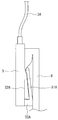
- FIG. 6 is an enlarged view of a narrow apparel 50A viewed from the right side of the box 5. It is the figure seen from the user's diagonally left back when the head mounted display 1 is mounted
- the head mounted display 1 includes a glasses-type frame 2 provided with a display unit 4 that displays an image according to image information on the retina of a user's eye, and a control unit 4A that controls the display unit 4. It is connected to the spectacles type frame 2 via a cable 3A and a cable 3B, and includes a box 5 including a battery (not shown) for supplying power to the display unit 4 and the control unit 4A.
- the eyeglass frame 2 includes a front part 20 and temples 21A and 21B formed in the direction of the box 5 from both ends of the front part 20.
- the cable 3A extends from the display unit 4 along the temple 21A, and electrically connects the display unit 4 and the control unit 4A to the battery included in the box 5.
- the cable 3 ⁇ / b> B extends along the temple 21 ⁇ / b> B from the end of the front portion 20 opposite to the display portion 4 and is connected to the box 5.
- the cable 3A and the cable 3B are provided with a curl structure 31A and a curl structure 31B, respectively, in a substantially middle portion.
- the box 5 is formed in a substantially rectangular parallelepiped shape, and a pair of left and right narrow applicators 50A and a narrow applicator 50A are provided at a predetermined interval for tightly attaching the box 5 to the user's collar.
- the box 5 has an outer side of the collar 6 (the shorter one of the double collars 6 is called the outer side. The longer side is called the inner side, and the user is positioned The same shall apply hereinafter).
- the right side surface of the box 5 has a rectangular shape, and a narrow accessory 50A is formed at the lower part of the side surface 52A of the box 5 facing the collar 6.
- the narrow accessory 50A is formed in a substantially L shape in a side view, and is formed in a direction in which an end portion of one side is in contact with the side surface 52A and a side side 51A that is the other side is in contact with the side surface 52A.
- the box 5 is placed on the outer collar of the collar 6, the side 51A is inserted between the double collars 6, and the tip of the side 51A and the side 52A of the box 5 are doubled.
- the box 5 is attached to the collar 6 by sandwiching one of the existing collars 6.
- the head-mounted display 1 is arranged so that the front part 20 of the eyeglass-type frame 2 is in front of the user's 8 eye, and each of the temple 21A and the temple 21B (shown in FIG. 1). It is mounted so that the end of the bridge is bridged over the user's ear.
- the box 5 is arranged on the back head side of the user 8 and is tightly attached to the collar 6 of the clothes worn by the user 8 by a narrow applicator 50A (shown in FIG. 2).
- the cable 3A and the cable 3B are provided with the curl structure 31A and the curl structure 31B, respectively. Accordingly, for example, even when the head of the user 8 is inclined and the cable 3A or the cable 3B is extended, the extension of the curl structure 31A or the curl structure 31B can be absorbed. Therefore, it is possible to prevent the glasses-type frame 2 from being pulled backward by the box 5 and thereby the glasses-type frame 2 being displaced.
- the box 5 is tightly fixed to the collar 6 and the head mounted display 1 is slightly pulled backward by the spring property of the curved structure 31B, so that the adhesion to the head (face) is strengthened. . Thereby, the mounting
- the cable 3A, the cable 3B, and the box 5 are fixed.
- the cable 3A, the cable 3B, and the box 5 are removable.
- the control unit 4A is arranged on the front unit 20, but in this embodiment, the control unit is provided inside the box.
- symbol is attached
- the head mounted display 1A includes a glasses-type frame 2 having a display unit 4 and a box 5A.
- the spectacles type frame 2 includes a front part 20 and temples 21A and temples 21B formed from both ends of the front part 20 in the direction of the box 5A. From both ends of the front portion 20, the cable 3A and the cable 3B extend along the temple 21A and the temple 21B. Further, at the ends of the cable 3A and the cable 3B, a convex connection terminal 31C and a convex connection terminal 31D made of, for example, a plug having a diameter of 3.5 ⁇ are provided.
- the box 5A is provided with a concave connection terminal 52 made of a jack that is electrically connected to the connection terminal 31C, and a concave connection terminal 53 made of a jack that can be connected to the connection terminal 31D.
- the box 5 ⁇ / b> A includes a battery that supplies power to the display unit 4 and a control unit (not shown) that controls the display unit 4.
- the ends of the temple 21A and the temple 21B are bridged over the ear in a state where the cable 3A and the cable 3B are separated from the box 5A. .
- the box 5A is attached to the collar 6 (shown in FIG. 4).
- the connection terminal 31C is connected to the connection terminal 52, and the connection terminal 31D is fitted to the connection terminal 53.
- the cable 3A and the cable 3B can be smoothly mounted without being obstructed.
- the control unit in the box 5A, the weight of the front unit 20 is reduced by the weight of the control unit compared to the case where the control unit is arranged on the front unit 20, and it is comfortable for the user. It is possible to provide a comfortable feeling.
- the cable stretchable structure is replaced with a curled structure and a cable winding structure.
- symbol is attached
- the head mounted display 1B is composed of a glasses-type frame 2 having a display unit 4 and a box 5A.
- the eyeglass-type frame 2 includes a front portion 20, a temple 21A, and a temple 21B.
- the head mounted display 1B includes a cable 3A and a cable 3B extending from the both ends of the front portion 20 in the direction of the box 5A along the temple 21A and the temple 21B, respectively.
- the cable 3A and the cable 3B include a cable winding mechanism 32A and a cable winding mechanism 32B in a substantially middle portion.
- the cable winding mechanism 32A includes a first storage portion 33A that stores the cable 3A
- the cable winding mechanism 32B includes a second storage portion 33B that stores the cable 3B.
- the cable winding mechanism 32A winds up the cable 3A and stores it in the storage portion 33A when the cable 3A is in the contracting direction.
- the cable winding mechanism 32B pulls out the cable stored from the storage portion 33B and absorbs the extension.
- the cable winding mechanism 32B winds the cable 3B and stores it in the storage portion 33B when the cable 3B is in the contracting direction. Note that the internal structures of the cable winding mechanism 32A and the cable winding mechanism 32B are well known, and thus detailed description thereof will be omitted.
- the head mounted display 1B includes the cable winding mechanism 32A and the cable winding mechanism 32B. Therefore, for example, the cable 3A or the cable 3B can be formed by tilting the user's head. Even in the direction in which the cable extends, the cable stored in the first storage part 33A or the second storage part 33B extends to absorb the extension.
- the narrow dressing is inserted between the double collars 6, and the side 51 ⁇ / b> A is inserted into the box 5 between the tip of the side 51 ⁇ / b> A and the side 52. It was supposed to be closed.
- the present invention is not limited to this.
- the box 5 is disposed outside the collar 6, and the narrow attachment 50B is formed on the upper portion of the side surface 52A.
- the narrow accessory 50B has a substantially key shape, and is formed in a direction in which one side is in contact with the side surface 52A and the other side 51B is in contact with the side surface 52A.
- the entire collar 6 may be sandwiched between the side surfaces 52A and the tip portions of the side edges 51B.
- the box 5 is arranged inside the collar 6, and the narrow wearing device 50C is formed from the upper part of the side surface 52A.
- the narrow accessory 50C has a substantially key shape, and is formed in a direction in which one side is in contact with the side surface 52A of the box 6 and the other side 51C is in contact with the side surface 52A.
- the entire collar 6 may be sandwiched between the side surface 52A and the tip of the side 51C.
- the side surface since the side surface opposite to the side surface 52A comes into contact with the user's skin, the side surface may be covered with gauze or the like. Thereby, it can prevent that the side surface on the opposite side to the side surface 52A touches a user's skin directly.
- the box 5 is attached to the collar 6 with the narrow fitting 50A as shown in FIG. 2, but the present invention is not limited to this.
- the side 5A and the collar 6 of the box 5 It is good also as what attaches a box fastener to the collar 6 by sticking a hook-and-loop fastener and bonding these together. Thereby, a narrow dressing can be manufactured easily.
- SYMBOLS 1 Head mounted display 2 ... Eyeglass type frame 3A, 3B ... Cable 4 ... Display part 5 ... Box 20 ... Front part 21A, 21B ... Temple 31A, 31B ... ⁇ Curl structure 31C, 31D, 52, 53... Connection terminal 32A, 32B... Cable winding mechanism 50A.
Landscapes
- Physics & Mathematics (AREA)
- General Physics & Mathematics (AREA)
- Optics & Photonics (AREA)
- Eyeglasses (AREA)
Abstract
ボックスが動く又はユーザの頭部が傾くことによって眼鏡型フレームが動くことによって表示部に表示された画像が見えなくなったり、また装着に違和感を覚えたりすることを防止可能なヘッドマウントディスプレイを提供する。 【解決手段】表示部4を備えた眼鏡型フレーム2から延伸するケーブル3A、3Bに、ケーブル伸縮構造31A、31Bを、またボックス5にユーザの襟に狭着する狭着具50Aを設ける。狭着具50Aによってボックス5が襟に狭着されるのでボックス5を安定させることができる。また。ユーザの頭部が傾いてケーブル3A、3Bが伸長した場合であっても、該伸長をケーブル伸縮構造31A、31Bによって吸収できるので眼鏡型フレーム2が動くのを防止できる。
Description
本発明は、ユーザの頭部に装着して使用するヘッドマウントディスプレイに関する。
近年、ユーザの頭部に装着されるタイプの画像表示装置、いわゆるヘッドマウントディスプレイ(Head Mounted Display : HMD)が広く知られている。このヘッドマウントディスプレイは、ユーザの眼前に配置しユーザに認識させるための画像を表示する表示部と、前記表示部をユーザの眼前に位置させるための支持部材、及び前記表示部に電力を供給するためのバッテリー等を含むボックスから構成される。前記支持部材は、頭部への装着が容易である等の理由から眼鏡型フレームが利用されることが多い。
ところで、前記支持部材として前記眼鏡型フレームを用いたヘッドマウントディスプレイでは、ユーザの眼前に配置される装置等は、装着性や安定性の観点からできるだけ軽量であることが望まれる。そのため、電力を供給するバッテリー等を含むボックスなどは、必ずしも眼前に配置する必要がなくて、ユーザの後頭部側の位置に配置されることが多い(例えば、特許文献1参照)。
しかしながら、ボックスは重くて安定しにくいため、ボックスが動くとそれに連れて眼鏡型フレームも動くことがある。また、ユーザの頭が傾いた場合、眼鏡型フレームが傾くこともある。このような場合、表示部に表示された画像が見えなくなったり、また装着に違和感を覚えたりすることがある。
本発明は、上記課題を解決するためになされたものであり、ボックスが動く又はユーザの頭部が傾くことによって眼鏡型フレームが動いてしまい、そのことによって、表示部に表示された画像が見えなくなったり、また装着に違和感を覚えたりすることを防止可能なヘッドマウントディスプレイを提供することを目的とする。
上記目的を達成するために、本発明に拘わるヘッドマウントディスプレイでは、ユーザの頭部に装着され、画像情報に応じた画像を前記ユーザの目の網膜に表示する表示部が配設された眼鏡型フレームと、前記表示部に電力を供給するバッテリーを含むボックスとからなるヘッドマウントディスプレイであって、前記表示部から前記眼鏡部フレームのテンプルに沿って前記ユーザの後頭部へと延伸され、前記表示部と前記ボックスとを電気的に接続するケーブルと、前記ケーブルの伸縮に応じて前記ケーブルを伸縮させるケーブル伸縮構造と、前記ボックスに設けられ、前記ユーザに着用されている衣服の襟元部分を狭着する狭着具と、を備えている。
この場合のヘッドマウントディスプレイでは、後方に配置されたボックスが動くことによって眼鏡型フレームが動き、表示部に表示された画像が見えなくなったり、また装着に違和感を覚えたりすることを防止することができる。
また、前記ヘッドマウントディスプレイでは、前記ケーブル伸縮構造は、前記ケーブルを長手方向に螺旋状に巻くことによって形成されたカール構造であるようにしても良い。前記ヘッドマウントディスプレイでは、ケーブル伸縮構造がカール構造であるので、本態様のヘッドマウントディスプレイを安価に、かつ、容易に製造することができる。また、カール構造にすることでケーブル部分の重量が重くならないので、ユーザに対して快適な付け心地を提供できる。
また、前記ヘッドマウントディスプレイでは、前記ケーブル伸縮構造は、前記ケーブルを収納する収納部と、前記ケーブルの前記伸縮に応じて、前記ケーブルを前記収納部から引き出し、又は前記ケーブルを前記収納部に収納するために巻き取るケーブル巻き取り機構と、を備えるようにしても良い。前記ヘッドマウントディスプレイでは、ケーブルを収納できる収納具を備えるので、ユーザはコードの取り扱いの煩わしさから解放され便利である。
また、前記ヘッドマウントディスプレイでは、前記ケーブルの、前記眼鏡型フレームとは逆方向の端部に形成された第一接続端子と、前記ボックスに設けられ、前記第一接続端子が接続されることによって前記表示部と前記ボックスとを電気的に接続する第二接続端子と、を備えるようししても良い。前記ヘッドマウントディスプレイでは、眼鏡型フレームとボックスとが装着前には、分離されているので、ユーザはヘッドマウントディスプレイを装着し易くなる。また、眼鏡型フレームとボックスとが分離されることによって装着前の持ち運びが便利になる。
また、前記ヘッドマウントディスプレイでは、前記ボックスは、前記表示部を制御するための制御部をさらに含むようにしても良い。前記ヘッドマウントディスプレイでは、制御部が眼鏡型フレームのフロント部に配置されたのと比べると、フロント部の重量が制御部の分だけ軽減されるので、ユーザが眼鏡型フレームから受ける重みを軽減でき、また装着時の安定性を増すことができる。
以下、本発明に係るヘッドマウントディスプレイを具現化したヘッドマウントディスプレイについて、図面を参照して説明する。なお、これらの図面は、本発明が採用しうる技術的特徴を説明するために用いられるものであり、記載されているヘッドマウントディスプレイの構成等は、単なる説明例である。
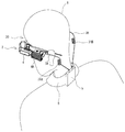
はじめに、第1実施の形態に係るヘッドマウントディスプレイの構成を説明する。図1に示すように、ヘッドマウントディスプレイ1は、画像情報に応じた画像をユーザの目の網膜に表示する表示部4、表示部4を制御する制御部4Aを配設した眼鏡型フレーム2、眼鏡型フレーム2にケーブル3A及びケーブル3Bを介して接続され、表示部4及び制御部4Aに電力を供給するバッテリー(図示せず)を含むボックス5から構成される。眼鏡型フレーム2は、フロント部20、フロント部20の両端からボックス5の方向に形成されたテンプル21A及びテンプル21Bから構成される。
ケーブル3Aは、表示部4からテンプル21Aに沿って延伸し、表示部4及び制御部4Aとボックス5に含まれるバッテリーとを電気的に接続する。ケーブル3Bは、フロント部20の表示部4とは反対側の端部からテンプル21Bに沿って延伸し、ボックス5に接続する。ケーブル3A及びケーブル3Bには、略中間部分にカール構造31A及びカール構造31Bがそれぞれ設けられている。ボックス5は、略直方体形状に形成され、ボックス5をユーザの襟に狭着させるための一定間隔をあけて左右一対の狭着具50A及び狭着具50Aが設けられている。
次に、図2を参照して、ボックス5に設けられた狭着具50Aの構造について説明する。図2に示すように、ボックス5は、襟6の外側(二重になっている襟6のうち短い方の襟側を外側という。また、長い方の襟側を内側といい、ユーザが位置する側とする。以下に同じ。)に配置されている。ボックス5の右側面は長方形状をしており、襟6と向かい合ったボックス5の側面52Aの下部に狭着具50Aが形成されている。狭着具50Aは、側面視略L字形に形成され、一辺の端部が側面52Aと接触し、他の一辺である側辺51Aが側面52Aと接触する方向に形成されている。ボックス5を襟6の外側の襟に配置し、側辺51Aを二重になっている襟6の間に挿入し、側辺51Aの先端部とボックス5の側面52Aとで二重になっている襟6のうちの一つを挟み込むことによって、ボックス5を襟6に装着する。
次に、図3を参照して、ヘッドマウントディスプレイ1がユーザに装着された際の装着形態について説明する。図に示すように、ヘッドマウントディスプレイ1は、眼鏡型フレーム2のフロント部20がユーザ8の眼前に来るように配置され、また、テンプル21Aとテンプル21B(供に、図1に示す)のそれぞれの端部がユーザの耳に架け渡されるように装着される。さらに、ボックス5は、ユーザ8の後頭部側に配置され、ユーザ8が着用している衣服の襟6に狭着具50A(図2に示す)によって狭着される。
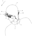
次に、図4を参照して、ユーザ8の頭部が傾いた際のカール構造31Bの動きを説明する。図に示すように、ヘッドマウントディスプレイ1を装着したユーザ8の頭部が、矢印9の方向(図に向かって左下)に傾いた場合、図に示すようにケーブル3Bに設けられたカール構造31Bが伸長する。これによって、ケーブル3Bの伸びをカール構造31Bで吸収できる。
以上のように、本実施の形態に係るヘッドマウントディスプレイ1では、ケーブル3A及びケーブル3Bにカール構造31A及びカール構造31Bがそれぞれ設けられている。これによって、例えばユーザ8の頭部が傾き、ケーブル3A又はケーブル3Bが伸長したような場合であっても、カール構造31A又はカール構造31Bのケーブルが伸びることによってこの伸長を吸収することができる。従って、ボックス5によって眼鏡型フレーム2が、後方に引っ張られ、それにより眼鏡型フレーム2がずれることを防ぐことができる。頭部8が傾くと、ボックス5が襟6に狭着固定されており、またカーブ構造31Bのバネ性によってヘッドマウントディスプレイ1が後方に軽く引っ張られるので頭部(顔)への密着性が強まる。これにより、ヘッドマウントディスプレイ1の装着性が高まり、装着が安定化する。
次に、図5を参照して、本発明に係るヘッドマウントディスプレイの第2実施の形態を説明する。第1実施の形態では、ケーブル3A及びケーブル3Bとボックス5とは固定されている構成であったが、本実施の形態では、ケーブル3A及びケーブル3Bと、ボックス5とは取り外し可能な構成としたものである。また、第1実施の形態では、制御部4Aをフロント部20に配置したが、本実施の形態では、ボックスの内部に制御部を設けたものとした。なお、第1実施の形態と同じ構造・機能を有するものについては同じ符号を付し、詳細な説明は割愛する。
図5に示すように、本実施の形態に係るヘッドマウントディスプレイ1Aは、表示部4を備えた眼鏡型フレーム2とボックス5Aとから構成される。眼鏡型フレームは2、フロント部20、フロント部20の両端からボックス5Aの方向に形成されたテンプル21A及びテンプル21Bから構成される。フロント部20の両端部からは、ケーブル3A及びケーブル3Bがテンプル21A及びテンプル21Bに沿って延伸している。また、ケーブル3A及びケーブル3Bの端部には、例えば口径3.5Φのプラグからなる凸形状の接続端子31C及び凸形状の接続端子31Dがそれぞれ設けられている。また、ボックス5Aには、接続端子31Cと電気的に接続するジャックからなる凹形状の接続端子52が、また接続端子31Dと接続可能なジャックからなる凹形状の接続端子53がそれぞれ設けられている。さらに、ボックス5Aには、表示部4に電力を供給するバッテリーと表示部4を制御する制御部(供に、図示しない)から構成される。
ユーザは、本実施の形態に係るヘッドマウントディスプレイ1Aを装着する際は、はじめに、ケーブル3A及びケーブル3Bとボックス5Aとを離間させた状態で、テンプル21A及びテンプル21Bの端部を耳に架け渡す。次にボックス5Aを襟6(図4に示す)に装着し、最後に接続端子31Cを接続端子52に接続させ、また接続端子31Dを接続端子53に嵌合させる。
以上のように、本実施の形態に係るヘッドマウントディスプレイ1Aでは、装着する際、ケーブル3A及びケーブル3Bが邪魔にならずにスムーズな装着が可能となる。また、制御部をボックス5Aに内蔵することによって、制御部がフロント部20に配置された場合と比較して、制御部の重さの分だけフロント部20の重さが軽減され、ユーザに快適な付け心地を提供することが可能となる。
次に、図6を参照して、本発明に係るヘッドマウントディスプレイの第3実施の形態を説明する。本実施の形態では、ケーブル伸縮構造をカール構造に代わりケーブルの巻き取り構造としたものである。なお、第2実施の形態と同じ構造・機能を有するものについては同じ符号を付し、詳細な説明は割愛する。
図6に示すように、本実施の形態に係るヘッドマウントディスプレイ1Bは、表示部4を備えた眼鏡型フレーム2とボックス5Aとから構成される。眼鏡型フレーム2は、フロント部20、テンプル21A及びテンプル21Bから構成される。
また、ヘッドマウントディスプレイ1Bは、フロント部20の両端からボックス5Aの方向にテンプル21A及びテンプル21Bに沿ってそれぞれ延伸するケーブル3A及びケーブル3Bを備える。ケーブル3A及びケーブル3Bは、略中間部にケーブル巻き取り機構32A及びケーブル巻き取り機構32Bを備える。ケーブル巻き取り機構32Aはケーブル3Aを収納する第1収納部33Aを備え、ケーブル巻き取り機構32Bはケーブル3Bを収納する第2収納部33Bを備える。ケーブル巻き取り機構32Aはケーブル3Aが伸長方向にある時は収納部33Aから収納されているケーブルを引き出し、該伸長を吸収する。また、ケーブル巻き取り機構32Aはケーブル3Aが縮む方向にある時は、ケーブル3Aを巻き取り、収納部33Aに収納する。
ケーブル巻き取り機構32Bはケーブル3Bが伸長方向にある時は収納部33Bから収納されているケーブルを引き出し、該伸長を吸収する。また、ケーブル巻き取り機構32Bはケーブル3Bが縮む方向にある時は、ケーブル3Bを巻き取り、収納部33Bに収納する。なお、ケーブル巻き取り機構32A及びケーブル巻き取り機構32Bの内部構造については、公知なのでここでの詳細な説明は割愛する。
ケーブル巻き取り機構32Bはケーブル3Bが伸長方向にある時は収納部33Bから収納されているケーブルを引き出し、該伸長を吸収する。また、ケーブル巻き取り機構32Bはケーブル3Bが縮む方向にある時は、ケーブル3Bを巻き取り、収納部33Bに収納する。なお、ケーブル巻き取り機構32A及びケーブル巻き取り機構32Bの内部構造については、公知なのでここでの詳細な説明は割愛する。
以上のように、本実施の形態に係るヘッドマウントディスプレイ1Bでは、ケーブル巻き取り機構32A及びケーブル巻き取り機構32Bが備えられているので、例えば、ユーザの頭部か傾くことによってケーブル3A又はケーブル3Bが伸長する方向にあっても、第1収納部33A又は第2収納部33Bに収納されているケーブルが延びることによって該伸長を吸収することができる。
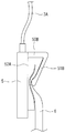
なお、本実施形態においては、狭着具を図2に示すように、二重になっている襟6の間に側辺51Aを挿入し、側辺51Aの先端部と側面52とでボックス5を狭着するものとした。しかし、これには限定されず、例えば図7に示すように、ボックス5を襟6の外側に配置し、側面52Aの上部に狭着具50Bを形成する。狭着具50Bは、略カギ形状であり、一辺が側面52Aと接触し、他の一辺である側辺51Bが側面52Aと接触する方向に形成されている。これら側面52Aと側辺51Bの先端部で襟6の全体を挟み込んでも良い。
また、図8に示すようにボックス5を襟6の内側に配置し、側面52Aの上部から狭着具50Cを形成する。狭着具50Cは略カギ形状であり、一辺がボックス6の側面52Aと接触し、他の一辺である側辺51Cが側面52Aと接触する方向に形成されている。これら側面52Aと側辺51Cの先端部とで襟6の全体を挟み込んでも良い。この場合においては、側面52Aと反対側の側面がユーザの肌と接触することになるので、該側面をガーゼ等で覆う構成としても良い。これにより、側面52Aと反対側の側面がユーザの肌に直接触れるのを防ぐことができる。
また、本実施の形態では、図2に示すように狭着具50Aでボックス5を襟6に装着するものとしたが、これには限定されず、例えばボックス5の側面52Aと襟6とに面ファスナを貼り、これらを貼り合わせることによりボックス5を襟6に装着させるものとしても良い。これにより、狭着具を容易に製造することができる。
1・・・ヘッドマウントディスプレイ
2・・・眼鏡型フレーム
3A、3B・・・ケーブル
4・・・表示部
5・・・ボックス
20・・・フロント部
21A、21B・・・テンプル
31A、31B・・・カール構造
31C、31D、52、53・・・接続端子
32A、32B・・・ケーブル巻き取り機構
50A・・・狭着具
2・・・眼鏡型フレーム
3A、3B・・・ケーブル
4・・・表示部
5・・・ボックス
20・・・フロント部
21A、21B・・・テンプル
31A、31B・・・カール構造
31C、31D、52、53・・・接続端子
32A、32B・・・ケーブル巻き取り機構
50A・・・狭着具
Claims (5)
- ユーザの頭部に装着され、画像情報に応じた画像を前記ユーザの目の網膜に表示する表示部が配設された眼鏡型フレームと、前記表示部に電力を供給するバッテリーを含むボックスとからなるヘッドマウントディスプレイであって、
前記表示部から前記眼鏡部フレームのテンプルに沿って前記ユーザの後頭部へと延伸され、前記表示部と前記ボックスとを電気的に接続するケーブルと、
前記ケーブルの伸縮に応じて前記ケーブルを伸縮させるケーブル伸縮構造と、
前記ボックスに設けられ、前記ユーザに着用されている衣服の襟元部分を狭着する狭着具と、
を備えることを特徴とするヘッドマウントディスプレイ。 - 前記ケーブル伸縮構造は、前記ケーブルを長手方向に螺旋状に巻くことによって形成されたカール構造であることを特徴とする請求項1に記載のヘッドマウントディスプレイ。
- 前記ケーブル伸縮構造は、
前記ケーブルを収納する収納部と、
前記ケーブルの前記伸縮に応じて、前記ケーブルを前記収納部から引き出し、又は前記ケーブルを前記収納部に収納するために巻き取るケーブル巻き取り機構と、
を備えることを特徴とする請求項1に記載のヘッドマウントディスプレイ。 - 前記ケーブルの、前記眼鏡型フレームとは逆方向の端部に形成された第一接続端子と、
前記ボックスに設けられ、前記第一接続端子が接続されることによって前記表示部と前記ボックスとを電気的に接続する第二接続端子と、
を備えることを特徴とする請求項1に記載のヘッドマウントディスプレイ。 - 前記ボックスは、前記表示部を制御するための制御部をさらに含むことを特徴とする請求項1に記載のヘッドマウントディスプレイ。
Applications Claiming Priority (2)
| Application Number | Priority Date | Filing Date | Title |
|---|---|---|---|
| JP2011043331A JP5413385B2 (ja) | 2011-02-28 | 2011-02-28 | ヘッドマウントディスプレイ |
| JP2011-043331 | 2011-02-28 |
Publications (1)
| Publication Number | Publication Date |
|---|---|
| WO2012117886A1 true WO2012117886A1 (ja) | 2012-09-07 |
Family
ID=46757825
Family Applications (1)
| Application Number | Title | Priority Date | Filing Date |
|---|---|---|---|
| PCT/JP2012/054070 Ceased WO2012117886A1 (ja) | 2011-02-28 | 2012-02-21 | ヘッドマウントディスプレイ |
Country Status (2)
| Country | Link |
|---|---|
| JP (1) | JP5413385B2 (ja) |
| WO (1) | WO2012117886A1 (ja) |
Cited By (1)
| Publication number | Priority date | Publication date | Assignee | Title |
|---|---|---|---|---|
| EP3370367A1 (en) | 2017-03-03 | 2018-09-05 | Iristick nv | System comprising a headset and a communication unit |
Families Citing this family (1)
| Publication number | Priority date | Publication date | Assignee | Title |
|---|---|---|---|---|
| KR102314500B1 (ko) * | 2014-12-26 | 2021-10-18 | 인텔 코포레이션 | 헤드 장착형 착용 디바이스 전력 공급 시스템 |
Citations (4)
| Publication number | Priority date | Publication date | Assignee | Title |
|---|---|---|---|---|
| JPH08146340A (ja) * | 1994-11-21 | 1996-06-07 | Olympus Optical Co Ltd | 頭部装着型映像表示装置 |
| JPH10294983A (ja) * | 1997-04-18 | 1998-11-04 | Olympus Optical Co Ltd | 頭部装着型映像表示装置 |
| JP2000111828A (ja) * | 1998-10-06 | 2000-04-21 | Sharp Corp | 装着型画像表示装置 |
| JP2002229670A (ja) * | 2001-01-02 | 2002-08-16 | Xybernaut Corp | 身体装着型コンピュータシステム |
-
2011
- 2011-02-28 JP JP2011043331A patent/JP5413385B2/ja not_active Expired - Fee Related
-
2012
- 2012-02-21 WO PCT/JP2012/054070 patent/WO2012117886A1/ja not_active Ceased
Patent Citations (4)
| Publication number | Priority date | Publication date | Assignee | Title |
|---|---|---|---|---|
| JPH08146340A (ja) * | 1994-11-21 | 1996-06-07 | Olympus Optical Co Ltd | 頭部装着型映像表示装置 |
| JPH10294983A (ja) * | 1997-04-18 | 1998-11-04 | Olympus Optical Co Ltd | 頭部装着型映像表示装置 |
| JP2000111828A (ja) * | 1998-10-06 | 2000-04-21 | Sharp Corp | 装着型画像表示装置 |
| JP2002229670A (ja) * | 2001-01-02 | 2002-08-16 | Xybernaut Corp | 身体装着型コンピュータシステム |
Cited By (3)
| Publication number | Priority date | Publication date | Assignee | Title |
|---|---|---|---|---|
| EP3370367A1 (en) | 2017-03-03 | 2018-09-05 | Iristick nv | System comprising a headset and a communication unit |
| WO2018172051A1 (en) | 2017-03-03 | 2018-09-27 | Iristick Nv | System comprising glasses and a communication unit |
| US10955679B2 (en) | 2017-03-03 | 2021-03-23 | Iristick Nv | System comprising glasses and a communication unit |
Also Published As
| Publication number | Publication date |
|---|---|
| JP5413385B2 (ja) | 2014-02-12 |
| JP2012182600A (ja) | 2012-09-20 |
Similar Documents
| Publication | Publication Date | Title |
|---|---|---|
| JP6307024B2 (ja) | 入力及び出力構造を有するウェアラブル・デバイス | |
| EP2831661B1 (en) | Head-wearable device with a display element | |
| US20130176626A1 (en) | Wearable device assembly with input and output structures | |
| WO2013134204A1 (en) | Eyeglass frame with input and output functionality | |
| CN111684340A (zh) | 眼睛佩戴物 | |
| WO2017221369A1 (ja) | ウェアラブル装置 | |
| US10517345B2 (en) | System and method for securing eyewear | |
| JP5199509B1 (ja) | 折り畳めるモダン | |
| JP5555366B1 (ja) | 眼鏡フレーム、ウェアラブルコンピュータ付眼鏡 | |
| JP5413385B2 (ja) | ヘッドマウントディスプレイ | |
| JP5147623B2 (ja) | 頭部装着型画像表示装置 | |
| JP6076121B2 (ja) | 眼鏡フレーム | |
| JP3541198B1 (ja) | 眼鏡用防塵具 | |
| JPWO2017104219A1 (ja) | ウェアラブル機器 | |
| JP2018189790A (ja) | 眼鏡フレーム | |
| CN217404634U (zh) | 一种观影眼镜 | |
| WO2021177206A1 (ja) | 眼鏡 | |
| JP3691006B2 (ja) | 防塵眼鏡 | |
| JP7742963B1 (ja) | 取り付け型蓄光眼鏡グリップ | |
| JP6723383B2 (ja) | 画像表示装置 | |
| JP2004233775A (ja) | ヘッドマウントディスプレイ | |
| JP4378738B1 (ja) | サイドミラー | |
| KR101808414B1 (ko) | 안경 및 모자의 탈착용 선글라스 | |
| US20250147324A1 (en) | Wearable video display | |
| JP3100421U (ja) | 眼鏡用防塵具 |
Legal Events
| Date | Code | Title | Description |
|---|---|---|---|
| 121 | Ep: the epo has been informed by wipo that ep was designated in this application |
Ref document number: 12751724 Country of ref document: EP Kind code of ref document: A1 |
|
| NENP | Non-entry into the national phase |
Ref country code: DE |
|
| 122 | Ep: pct application non-entry in european phase |
Ref document number: 12751724 Country of ref document: EP Kind code of ref document: A1 |