WO2012117493A1 - 金属材の特性測定装置 - Google Patents
金属材の特性測定装置 Download PDFInfo
- Publication number
- WO2012117493A1 WO2012117493A1 PCT/JP2011/054481 JP2011054481W WO2012117493A1 WO 2012117493 A1 WO2012117493 A1 WO 2012117493A1 JP 2011054481 W JP2011054481 W JP 2011054481W WO 2012117493 A1 WO2012117493 A1 WO 2012117493A1
- Authority
- WO
- WIPO (PCT)
- Prior art keywords
- metal material
- pulse
- pulsed
- laser
- laser beam
- Prior art date
- Legal status (The legal status is an assumption and is not a legal conclusion. Google has not performed a legal analysis and makes no representation as to the accuracy of the status listed.)
- Ceased
Links
Images






Classifications
-
- G—PHYSICS
- G01—MEASURING; TESTING
- G01N—INVESTIGATING OR ANALYSING MATERIALS BY DETERMINING THEIR CHEMICAL OR PHYSICAL PROPERTIES
- G01N29/00—Investigating or analysing materials by the use of ultrasonic, sonic or infrasonic waves; Visualisation of the interior of objects by transmitting ultrasonic or sonic waves through the object
- G01N29/04—Analysing solids
-
- G—PHYSICS
- G01—MEASURING; TESTING
- G01N—INVESTIGATING OR ANALYSING MATERIALS BY DETERMINING THEIR CHEMICAL OR PHYSICAL PROPERTIES
- G01N21/00—Investigating or analysing materials by the use of optical means, i.e. using sub-millimetre waves, infrared, visible or ultraviolet light
- G01N21/17—Systems in which incident light is modified in accordance with the properties of the material investigated
- G01N21/1702—Systems in which incident light is modified in accordance with the properties of the material investigated with opto-acoustic detection, e.g. for gases or analysing solids
-
- G—PHYSICS
- G01—MEASURING; TESTING
- G01B—MEASURING LENGTH, THICKNESS OR SIMILAR LINEAR DIMENSIONS; MEASURING ANGLES; MEASURING AREAS; MEASURING IRREGULARITIES OF SURFACES OR CONTOURS
- G01B9/00—Measuring instruments characterised by the use of optical techniques
- G01B9/02—Interferometers
-
- G—PHYSICS
- G01—MEASURING; TESTING
- G01N—INVESTIGATING OR ANALYSING MATERIALS BY DETERMINING THEIR CHEMICAL OR PHYSICAL PROPERTIES
- G01N29/00—Investigating or analysing materials by the use of ultrasonic, sonic or infrasonic waves; Visualisation of the interior of objects by transmitting ultrasonic or sonic waves through the object
- G01N29/22—Details, e.g. general constructional or apparatus details
- G01N29/24—Probes
- G01N29/2418—Probes using optoacoustic interaction with the material, e.g. laser radiation, photoacoustics
-
- G—PHYSICS
- G01—MEASURING; TESTING
- G01N—INVESTIGATING OR ANALYSING MATERIALS BY DETERMINING THEIR CHEMICAL OR PHYSICAL PROPERTIES
- G01N29/00—Investigating or analysing materials by the use of ultrasonic, sonic or infrasonic waves; Visualisation of the interior of objects by transmitting ultrasonic or sonic waves through the object
- G01N29/44—Processing the detected response signal, e.g. electronic circuits specially adapted therefor
- G01N29/46—Processing the detected response signal, e.g. electronic circuits specially adapted therefor by spectral analysis, e.g. Fourier analysis or wavelet analysis
-
- G—PHYSICS
- G01—MEASURING; TESTING
- G01N—INVESTIGATING OR ANALYSING MATERIALS BY DETERMINING THEIR CHEMICAL OR PHYSICAL PROPERTIES
- G01N2291/00—Indexing codes associated with group G01N29/00
- G01N2291/02—Indexing codes associated with the analysed material
- G01N2291/023—Solids
- G01N2291/0234—Metals, e.g. steel
Definitions
- the present invention relates to a metal material property measuring apparatus using laser light.
- the strength of the metal material there is a strong correlation between the strength of the metal material and the crystal grain size. If the crystal grain size is reduced from several tens of ⁇ m to about 1 ⁇ m, not only the strength is high, but also the moldability and recyclability are excellent. It is known that high performance metal materials can be obtained. Such quality control of a metal material is often performed by a destructive test. For example, a test piece is cut out from a rolled product coil, and the strength is confirmed by a tensile test or the like. However, such a method has a long lead time of several hours to several days until a measured value is obtained, and it is impossible to prevent the occurrence of defective products during that time.
- the characteristics of a metal material detected using the propagation behavior of pulsed ultrasound are various, such as crystal grain size, elastic modulus, formability (r value), and elastic wave velocity. Also, it is known that there is a strong correlation between the crystal grain size of the metal material and the tensile strength, yield strength, and yield elongation, and the same measurement method as the crystal grain size measurement method of the metal material Thus, these characteristic values can also be obtained.
- Pulse ultrasonic waves caused by scattering at grain boundaries not only “attenuation” but also “(ii) diffusion of pulsed ultrasonic waves in a direction other than straight ahead” reduces the amplitude of the pulsed ultrasonic waves.
- the amplitude of the pulse ultrasonic wave is reduced, the signal-to-noise ratio is deteriorated, and the measurement accuracy of the characteristic measuring device is lowered.
- the propagation directions of the pulse ultrasonic waves are not aligned in the direction perpendicular to the irradiation surface of the pulse laser light, and the pulse ultrasonic waves diffuse to the periphery as if the spot size is small. For this reason, the amplitude of the pulse ultrasonic wave is remarkably reduced with respect to the propagation distance, and the signal-to-noise ratio of the detected pulse ultrasonic wave waveform is deteriorated. As a result, there is a problem that measurement accuracy is lowered.
- an object of the present invention is to provide a metal material property measuring apparatus using pulsed laser light in which a decrease in measurement accuracy is suppressed.
- a laser oscillator that emits pulsed laser light
- a plurality of small lenses having the same shape spread in a matrix on a surface perpendicular to the optical axis of the pulsed laser light.
- a lens array arranged so that a part of the pulse laser beam divided into the beam cross section is incident on each of the plurality of small lenses, and (c) light emitted from the plurality of small lenses of the lens array
- a condensing lens that condenses light on the same surface of the metal material, and (d) detects pulsed ultrasonic waves that have been excited by the pulsed laser light collected by the condensing lens and propagated inside the metal material as electrical signals.
- a metal material property measuring apparatus including a laser interferometer that performs (e) a signal processing apparatus that processes an electrical signal.
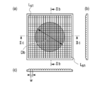
- FIGS. 2A and 2B are schematic views illustrating a configuration example of a lens array included in the metal material characteristic measuring apparatus according to the first embodiment of the present invention, in which FIG. 2A is a plan view and FIG. 2B is FIG.
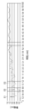
- FIG. 2C is a cross-sectional view taken along the IIc-IIc direction of FIG. 2A. It is a photograph which shows the example of the condensing spot shape by the metal material characteristic measuring apparatus which concerns on the 1st Embodiment of this invention. It is a graph which shows the example of the detection waveform of the pulsed ultrasonic wave excited inside the metal material to be measured.
- FIG.6 (a) shows Gaussian distribution
- FIG.6 (b) shows uniform distribution.
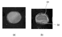
- FIG. 11A is a photograph showing the beam profile before the change with time
- FIG. 11B is a photograph showing the beam profile after the change with time. .
- first and second embodiments of the present invention will be described with reference to the drawings.
- the same or similar parts are denoted by the same or similar reference numerals.
- the following first and second embodiments exemplify apparatuses and methods for embodying the technical idea of the present invention, and the embodiments of the present invention are structures, arrangements, etc. of components. Is not specified as follows.
- the embodiment of the present invention can be variously modified within the scope of the claims.
- a metal material property measuring apparatus 1 As shown in FIG. 1, a metal material property measuring apparatus 1 according to a first embodiment of the present invention has a laser oscillator 10 that emits pulsed laser light Lp, and a surface perpendicular to the optical axis of the pulsed laser light Lp.
- the lens array 20 having a plurality of small lenses Ls having the same shape spread in a matrix and the emitted light Ld from the plurality of small lenses Ls are condensed on the same region of the surface 101 of the metal material 100 to be measured.
- the condenser lens 30 and the analysis device 40 that analyzes the pulsed ultrasonic wave SW that is irradiated with the outgoing light Ld and propagates through the metal material 100 are provided.
- a part of the beam section perpendicular to the optical axis of the pulsed laser light Lp is incident on each of the plurality of small lenses Ls of the lens array 20, and the plurality of small lenses Ls have a shape of a beam section perpendicular to the optical axis.
- the surface 101 of the metal material 100 is irradiated with the pulse laser light Lp to cause a small-scale explosion, and the metal material 100 is subjected to pulse ultrasonic waves.
- SW is excited.
- the pulse ultrasonic wave SW attenuates while propagating through the metal material 100 and appears as minute vibrations of the back surface 102 of the metal material 100 facing the surface 101 irradiated with the pulse laser beam Lp.
- FIG. 1 shows an example in which a laser interferometer 41 is employed as a detection device.
- the laser interferometer 41 detects pulsed ultrasonic waves that are excited by the pulsed laser light Lp collected by the condenser lens 30 and propagate inside the metal material 100 as electrical signals. Specifically, the laser interferometer 41 irradiates the back surface 102 of the metal material 100 with weak detection laser light Lf, and causes the reflected light Lr of the detection laser light Lf from the metal material 100 to interfere with the reference light. Thus, the minute vibration appearing on the back surface 102 of the metal material 100 is detected as a change in voltage.
- the electrical signal detected by the laser interferometer 41 is processed by the signal processing device 42 of the analysis device 40, and the characteristics of the metal material 100 are measured.
- the detected electrical signal is taken into the signal processing computer 422 via the digital oscilloscope 421, and the characteristics of the metal material 100 are determined by waveform analysis.
- the laser oscillator 10 can employ, for example, a Q-switched solid-state pulse laser with high output and stable characteristics.
- Q-switched solid-state pulse lasers with a pulse width of several ns to several tens of ns using neodymium-doped yttrium aluminum garnet (Nd: YAG) as the solid medium for oscillation are widely used in industrial applications. 10 is preferable.
- the pulsed laser light Lp emitted from the laser oscillator 10 generally has a slight divergence angle. For this reason, the pulsed laser light Lp that has been made substantially parallel using the magnifying system 11 that combines the concave lens 111 and the convex lens 112 is incident on the lens array 20.
- the lens array 20 has a structure in which a large number of small lenses Ls having the same shape are spread on a surface perpendicular to the optical axis of the incident pulse laser beam Lp.
- FIG. 2 shows n square small lenses Ls1 to Lsn. Shows an example arranged in a matrix.
- the hatched area in FIG. 2A is an area irradiated with the pulse laser beam Lp, and the beam diameter of the pulse laser beam Lp is Db.
- the small lenses Ls are arranged in the lens array 20 without any gap.
- the interval w between the small lenses Ls shown in FIG. 2C is determined so that a sufficient number of small lenses Ls are included in the beam cross section of the incident pulse laser light Lp as will be described later.
- the “interval between the small lenses Ls” is a distance between the centers of the adjacent small lenses Ls.
- the pulse laser beam Lp divided in the beam cross section is divided into individual small lenses Ls constituting the lens array 20 arranged to be included in the beam cross section of the pulse laser beam.
- each of the small lenses Ls forms an image of the shape of the small lens Ls (for example, a square).
- the emitted light Ld of each small lens Ls produced from a very small part of the pulse laser light Lp. Has a uniform light quantity distribution.
- Each outgoing light Ld emitted from the lens array 20 is condensed on the surface 101 of the metal material 100 by a condensing lens 30 of a convex lens.
- the focal length of the condensing lens 30 is substantially equal to the stand-off distance SD (interval between the condensing lens 30 and the surface 101 of the metal material 100).
- each image by the plurality of small lenses Ls is projected onto the focal position of the condenser lens 30, that is, one point on the surface 101 of the metal material 100.
- the pulse laser beam is formed so that the condensing spot SP irradiated with the plurality of pulse laser beams having the same shape (for example, a square) as the small lens Ls and having a uniform light amount distribution is formed on the surface 101 of the metal material 100.
- Lp is shaped.
- the shape of the condensing spot SP is the same as the shape of the small lens Ls, and the size is determined by the focal length of the condensing lens 30.
- the images projected by the plurality of small lenses Ls are superimposed, so that light and dark due to interference fringes occur.
- the interval between the interference fringes can be made extremely small, and a substantially uniform light amount distribution can be obtained in the focused spot SP.
- the number of images to be superimposed is less than 15, the influence of interference fringes on the waveform of the pulsed ultrasonic wave SW propagating inside the metal material 100 may not be negligible, and the effect of uniformizing the amount of light is insufficient. There is a case. Therefore, the interval of the small lenses Ls in the lens array 20 is set so that 15 or more small lenses Ls are included in the beam cross section of the incident pulsed laser light Lp.
- the focal length of the lens array 20 is determined by experiment or ray tracing simulation calculation so that the size of the focused spot SP formed on the surface 101 of the metal material 100 becomes a desired value. Practically, the focal length of the lens array 20 ranges from about the same as the standoff distance SD to about 1/10 of the standoff distance SD. Since there are various restrictions in manufacturing the lens array 20, there may be a case where the small lens Ls having a desired focal length cannot be obtained. In this case, a plurality of lens arrays 20 may be arranged in combination.
- the material of the lens array 20 is preferably made of glass having a high damage threshold such as quartz glass.
- a plastic lens array 20 or the like may be employed depending on the wavelength and output required for measuring the characteristics of the metal material 100.
- FIG. 3 shows an example in which the shape of the condensing spot SP on the surface 101 of the metal material 100 is baked and recorded on the burn paper.
- FIG. 3 shows a condensing spot SP formed by incidence of a pulse laser beam Lp having a beam diameter Db of 14 mm on a lens array 20 in which small lenses Ls are arranged in a matrix of 18 rows and 18 columns at intervals of 1.1 mm. Shape. Therefore, FIG. 3 shows an example in which images of about 127 small lenses Ls are superimposed. It can be seen that the shape of the focused spot SP is the same square as the shape of the small lens Ls of the lens array 20, and the shape of the small lens Ls is projected with good overlap. In the example shown in FIG. 3, the size Ds of the focused spot SP is 4.5 mm.
- the pulse ultrasonic wave SW is excited in the metal material 100 by the irradiation of the pulse laser beam Lp to the focused spot SP, and this pulse ultrasonic wave SW propagates in the metal material 100.
- the pulsed ultrasonic wave SW excited by the metal material 100 has various vibration mode components.
- a repetitive reflection echo of a longitudinal wave component (a pointed portion of a waveform indicated by an arrow in FIG. 4) is used.
- waveforms E1, E2, and E3 are a longitudinal echo, a first echo, a second echo, and a third echo, respectively.
- the vertical axis indicates relative amplitude (unit a.u .: Arbitrary Unit).
- the horizontal axis represents the elapsed time after the pulse laser beam Lp is emitted.
- the first echo is detected when the pulse ultrasonic wave SW first reaches the back surface 102 of the metal material 100.
- the reflected echo after the second echo is detected at the time when the pulse ultrasonic wave SW reflected by the front surface 101 reaches the back surface 102 after being reflected by the back surface 102. Therefore, the time until the first echo is detected corresponds to the thickness of the metal material 100, and the interval at which each subsequent echo is detected corresponds to twice the thickness of the metal material 100.
- FIG. 5 is a schematic diagram showing how the pulse ultrasonic wave SW transmitted from the flat piston sound source 500 is diffused.
- d the diameter of the piston sound source 500 and corresponds to the spot size of the pulsed laser light Lp irradiated on the metal material 100.
- ⁇ is the wavelength (mm) of the pulse ultrasonic wave SW.
- a region far from the near field limit distance x is called a far field, and the pulse ultrasonic wave SW is diffused as a spherical wave Ws.
- the amplitude of the pulsed ultrasonic wave SW rapidly decreases in proportion to the square of the propagation distance regardless of the material characteristics such as the crystal grain size. Therefore, in order to clearly detect the pulsed ultrasonic wave SW used for waveform analysis, it is preferable to increase the spot size and make the near field limit distance x longer.
- the propagation distance of the fifth echo is expressed by the following equation (2).
- the above-described examination of the diffusion of the pulse ultrasonic wave SW is based on the plate-like piston sound source 500.
- the light amount distribution (beam profile) in the beam cross section of the pulse laser beam Lp emitted from the laser oscillator 10 is not necessarily uniform.
- the light intensity distribution of pulsed laser light from laser oscillators widely used in industrial applications is a "Gaussian distribution (normal distribution)" with a large amount of light near the center of the beam and good condensing by a convex lens, or a distribution close to it. It is.
- the beam profile has a Gaussian distribution as shown in FIG. 6A
- the light amount near the beam center and the peripheral light amount are compared with the case where the beam profile shown in FIG. 6B is uniform.
- shaft of Fig.6 (a) and FIG.6 (b) shows a light quantity
- a horizontal axis shows the position in a condensing spot.
- the plurality of small lenses Ls constituting the lens array 20 project an image having a uniform light amount distribution on the focal position of the condenser lens 30.
- the pulsed laser light Lp has a uniform light amount distribution in the same shape as the small lens LS on the surface 101 of the metal material 100, and forms a condensing spot with a light amount distribution as shown in FIG. 6B. It is shaped.
- the diffusion of the pulse ultrasonic wave SW excited on the metal material 100 by the pulse laser beam Lp can be suppressed to a small level.
- the amplitude of the pulse ultrasonic wave SW is unlikely to decrease with respect to the propagation distance.
- the pulsed ultrasonic wave SW excited by the pulse laser beam Lp propagates through the metal material 100, and minute vibrations appearing on the back surface 102 of the metal material 100 are detected as an electrical signal by the laser interferometer 41. Since the decrease in the amplitude of the pulse ultrasonic wave SW is suppressed as described above, the signal-to-noise ratio of the ultrasonic waveform detected by the laser interferometer 41 is improved, and good measurement accuracy can be obtained.
- a photorefractive interferometer capable of measuring high-frequency vibration even when the surface 101 of the metal material 100 is rough can be employed.
- a Fabry-Perot interferometer can be similarly used because it can measure high-frequency vibrations on a rough surface.
- a Michelson interferometer or the like can be employed.
- the voltage waveform detected by the laser interferometer 41 is recorded in, for example, a digital oscilloscope 421 and analyzed by the signal processing computer 422, whereby the characteristics of the metal material 100 can be measured.
- the attenuation factor due to scattering of longitudinal wave ultrasonic crystal grains propagating through the metal material 100 varies depending on the frequency of the longitudinal wave ultrasound and the crystal grain size of the metal material 100. For example, Rayleigh scattering and stochastic scattering are known.
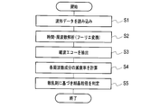
- step S1 in FIG. 7 The waveform data read in step S1 in FIG. 7 is decomposed into frequency components by Fourier transform or the like in step S2. Next, in step S3, each longitudinal wave echo is extracted in each frequency component. In step S4, the change in the amplitude of the extracted longitudinal wave echo is approximated by a logarithmic function, and the attenuation rate ⁇ (f) of each frequency component is calculated.
- ⁇ is an attenuation factor (dB / mm)
- D is a crystal grain size (mm)
- f is a frequency (MHz)
- K and n are coefficients.
- step S5 the crystal grain size is determined using Equation (4) based on the attenuation rate ⁇ (f) of any frequency f.
- the values of the coefficients K and n are identified in advance by an experiment for measuring a test material having a known crystal grain size.
- FIG. 8 is an example of an ultrasonic waveform detected by the metal material property measuring apparatus 1 according to the first embodiment.
- the vertical axis indicates relative amplitude (unit a.u .: Arbitrary Unit).
- the horizontal time is the elapsed time after the pulse laser beam Lp is emitted.
- the metal material 100 to be measured is a steel plate having a plate thickness of 1.35 mm, and the crystal grain size is about 4 ⁇ m.
- the ultrasonic waveform detected by the laser interferometer 41 can be clearly detected from the first echo (waveform E1) to the thirteenth echo (waveform E13) of the longitudinal wave.
- the metal material property measuring apparatus 1 As described above, according to the metal material property measuring apparatus 1 according to the first embodiment of the present invention, the light quantity distribution in the beam cross section of the pulse laser beam irradiated to the metal material 100 to be measured is uniform. Can be. For this reason, diffusion of the pulsed ultrasonic wave SW excited by the metal material 100 is suppressed. As a result, a metal material property measuring apparatus 1 using a pulse laser beam, in which a decrease in measurement accuracy is suppressed, is provided.
- the positional relationship between the condenser lens 30 and the lens array 20 may be reversed from the front and back of the example shown in FIG. That is, the lens array 20 may be disposed between the laser oscillator 10 and the condenser lens 30, or the condenser lens 30 may be disposed between the laser oscillator 10 and the lens array 20. .
- FIG. 9 shows an example in which the condenser lens 30 is disposed between the laser oscillator 10 and the lens array 20. Also with the characteristic measuring apparatus 1 shown in FIG. 9, the emitted light Ld output from each of the plurality of small lenses Ls of the lens array 20 is condensed by the condenser lens 30 onto the same region of the surface 101 of the metal material 100 to be measured. Can be made.
- a window plate 51 is installed between the lens array 20 and the condenser lens 30 and the metal material 100.
- the window plate 51 is installed in the casing 50 in order to emit the pulsed laser light Lp to the outside from the casing 50 in which the laser oscillator 10, the lens array 20, and the condenser lens 30 are stored.
- Optical devices such as laser oscillators, lenses, and reflectors are often made of special materials or special coatings to increase their optical efficiency. Damage or decrease optical efficiency. Therefore, it is common to place the entire device in a highly sealed casing and to extract laser light through a window plate.
- the light quantity distribution of the pulse laser beam can be made uniform at the condensing spot SP on the surface 101 of the metal material 100. That is, even if the beam profile of the pulsed laser light Lp passing through the window plate 51 deteriorates due to damage to the portion of the window plate 51 to which liquid or powder adheres, the diffusion of the pulsed ultrasonic wave SW excited by the metal material 100 does not occur. Can be kept small. As a result, the amplitude of the pulse ultrasonic wave SW hardly decreases with respect to the propagation distance, and the signal-to-noise ratio of the ultrasonic waveform detected by the laser interferometer 41 hardly changes.
- the window plate 51 even when the window plate 51 is damaged, it is possible to maintain good measurement accuracy. Therefore, even if the window plate 51 is damaged, it is not necessary to replace it immediately, and the window plate 51 may be replaced in accordance with the suspension period on the production schedule. For this reason, it is possible to avoid a decrease in the operating rate of the characteristic measuring apparatus 1.
- the metal material property measuring apparatus 1 As shown in FIG. 10, the metal material property measuring apparatus 1 according to the second embodiment of the present invention further includes a wavelength conversion crystal 60 that converts the wavelength of the pulsed laser light Lp emitted from the laser oscillator 10. However, this is different from the first embodiment shown in FIG. About another structure, it is the same as that of 1st Embodiment.
- the absorption rate of the laser beam on the polished surface 101 of the metal material 100 is larger as the wavelength is shorter. Therefore, the pulse laser beam Lp emitted from the laser oscillator 10 is converted into a short wavelength by the wavelength conversion crystal 60 and then irradiated onto the metal material 100, so that the same pulse is generated in a metal material having a high reflectance such as a polished surface.
- the pulsed ultrasonic wave SW having a larger amplitude can be excited with respect to the laser light output.
- the pulse laser light Lp emitted from the laser oscillator 10 is irradiated to the metal material 100 after being converted into a shorter wavelength by the wavelength conversion crystal 60.
- the absorption rate of the pulse laser beam on the surface 101 of the metal material 100 is larger, so that the pulse ultrasonic wave SW having a larger amplitude can be excited with respect to the same pulse laser beam output on the polished surface or the like.
- pulse laser light Lp from an Nd: YAG laser having a wavelength of 1064 nm is converted into a pulse laser light Lp having a wavelength of 532 nm or 355 nm by a wavelength conversion crystal 60 such as LBO (LiB 3 O 5 ) or KTP (KTiOPO 4 ). It converts and irradiates the surface 101 of the metal material 100.
- a wavelength conversion crystal 60 such as LBO (LiB 3 O 5 ) or KTP (KTiOPO 4 ). It converts and irradiates the surface 101 of the metal material 100.
- the light density of the pulsed laser light Lp incident on the wavelength conversion crystal 60 is set to a damage threshold value or less. Therefore, if the output of the pulse laser beam Lp to be used is large, it is necessary to use the wavelength conversion crystal 60 having a large size and increase the beam diameter of the incident pulse laser beam Lp.
- FIGS. 11A and 11B show examples of beam profile changes with time when the wavelength of YAG laser light is converted to 532 nm.
- 11A shows the beam profile immediately after the start of use
- FIG. 11B shows the beam profile after 10 months.
- the characteristic measuring apparatus 1 shown in FIG. 10 even if the beam profile is deteriorated due to the secular change or temperature unevenness of the wavelength conversion crystal 60, the condensed spot SP on the surface 101 of the metal material 100.
- the light quantity distribution of the pulse laser beam can be made uniform. For this reason, the diffusion of the pulsed ultrasonic wave SW excited by the metal material 100 can be kept small. As a result, the amplitude of the pulsed ultrasonic wave SW is less likely to decrease with respect to the propagation distance, the signal-to-noise ratio of the ultrasonic waveform detected by the laser interferometer 41 is improved, and good measurement accuracy can be obtained. .
- the metal material property measuring apparatus of the present invention can be used in a manufacturing industry that measures the properties of a metal material in a non-contact manner.
Landscapes
- Physics & Mathematics (AREA)
- General Physics & Mathematics (AREA)
- Immunology (AREA)
- Biochemistry (AREA)
- Pathology (AREA)
- Health & Medical Sciences (AREA)
- Life Sciences & Earth Sciences (AREA)
- Chemical & Material Sciences (AREA)
- Analytical Chemistry (AREA)
- General Health & Medical Sciences (AREA)
- Signal Processing (AREA)
- Engineering & Computer Science (AREA)
- Mathematical Physics (AREA)
- Spectroscopy & Molecular Physics (AREA)
- Optics & Photonics (AREA)
- Acoustics & Sound (AREA)
- Investigating Or Analyzing Materials By The Use Of Ultrasonic Waves (AREA)
Abstract
Description
本発明の第1の実施形態に係る金属材の特性測定装置1は、図1に示すように、パルスレーザ光Lpを出射するレーザ発振器10と、パルスレーザ光Lpの光軸と垂直な面にマトリクス状に敷き詰められた複数の同一形状の小レンズLsを有するレンズアレイ20と、複数の小レンズLsからの出射光Ldを測定対象の金属材100の表面101の同一領域に重ねて集光させる集光レンズ30と、出射光Ldが照射されて金属材100の内部を伝播するパルス超音波SWを解析する解析装置40とを備える。レンズアレイ20の複数の小レンズLsには、パルスレーザ光Lpの光軸に垂直なビーム断面について分割した一部がそれぞれ入射され、複数の小レンズLsは光軸に垂直なビーム断面の形状が互いに同一の出射光Ldをそれぞれ出射する
図1に示した特性測定装置1では、金属材100の表面101にパルスレーザ光Lpを照射して小規模な爆発を起こし、金属材100にパルス超音波SWを励起させる。このパルス超音波SWは金属材100内を伝播しながら減衰し、パルスレーザ光Lpが照射された表面101に対向する金属材100の裏面102の微小な振動として現れる。
x=d2/(4λ) ・・・(1)
式(1)において、dはピストン音源500の直径であり、金属材100に照射されたパルスレーザ光Lpのスポットサイズに相当する。λはパルス超音波SWの波長(mm)である。
2(mm)×(1+4×2(往復))=18(mm) ・・・(2)
鋼材の縦波超音波の伝播速度vは約5900m/sなので、30MHzの縦波超音波の波長λ=v/fは、0.197mmである。したがって、式(1)によれば、波形解析に30MHz以上の周波数成分を用いる場合、スポットサイズの直径を4mm程度以上にすることが好ましいことが分かる。
α=K×Dn-1×fn ・・・(3)
式(3)で、αは減衰率(dB/mm)、Dは結晶粒径(mm)、fは周波数(MHz)、K及びnは係数である。
D={α/(K×fn)}1/(n-1) ・・・(4)
ステップS5において、いずれかの周波数fの減衰率α(f)に基づき、式(4)を用いて結晶粒径を判定する。なお、係数K、nの値は、結晶粒径が既知の試験材を測定する実験によって予め同定される。係数nの値は、理論的には結晶粒径Dと波長λの比D/λに応じて定まる。即ち、レイリー散乱域(0.03≦D/λ≦0.3)でn=4、ストかスティック散乱域(0.3≦D/λ≒1)でn=3である。
本発明の第2の実施形態に係る金属材の特性測定装置1は、図10に示すように、レーザ発振器10から出射されたパルスレーザ光Lpの波長を変換する波長変換結晶60を更に備えることが、図1に示した第1の実施形態と異なる点である。その他の構成については、第1の実施形態と同様である。
10…レーザ発振器
11…拡大系
20…レンズアレイ
30…集光レンズ
40…解析装置
41…レーザ干渉計
42…信号処理装置
50…筐体
51…窓板
60…波長変換結晶
100…金属材
101…表面
102…裏面
111…凹レンズ
112…凸レンズ
421…デジタルオシロスコープ
422…信号処理コンピュータ
Claims (3)
- パルスレーザ光を出射するレーザ発振器と、
前記パルスレーザ光の光軸と垂直な面にマトリクス状に敷き詰められた複数の同一形状の小レンズを有し、前記複数の小レンズの各々に前記パルスレーザ光をビーム断面について分割した一部分が入射するように配置されたレンズアレイと、
前記レンズアレイの前記複数の小レンズからの出射光を測定対象の金属材の表面の同一領域に重ねて集光させる集光レンズと、
前記集光レンズにより集光された前記パルスレーザ光により励起され前記金属材の内部を伝播したパルス超音波を電気信号として検出するレーザ干渉計と、
前記電気信号を処理する信号処理装置と
を備えることを特徴とする金属材の特性測定装置。 - 前記レーザ発振器と前記レンズアレイの間に前記レーザ発振器から出射された前記パルスレーザ光の波長を変換する波長変換結晶を更に備えることを特徴とする請求項1に記載の金属材の特性測定装置。
- 前記レーザ干渉計が、前記パルス超音波の縦波成分の繰り返し反射エコーを検出することを特徴とする請求項1に記載の金属材の特性測定装置。
Priority Applications (9)
| Application Number | Priority Date | Filing Date | Title |
|---|---|---|---|
| KR1020157017076A KR101610608B1 (ko) | 2011-02-28 | 2011-02-28 | 금속재의 특성 측정 장치 |
| PCT/JP2011/054481 WO2012117493A1 (ja) | 2011-02-28 | 2011-02-28 | 金属材の特性測定装置 |
| CN201180068508.XA CN103403537B (zh) | 2011-02-28 | 2011-02-28 | 金属材料的特性测定装置 |
| DE112011104977.3T DE112011104977B4 (de) | 2011-02-28 | 2011-02-28 | Eigenschaftmesssystem für ein Metallmaterial |
| JP2013502070A JP5715234B2 (ja) | 2011-02-28 | 2011-02-28 | 金属材の特性測定装置 |
| CA2825892A CA2825892C (en) | 2011-02-28 | 2011-02-28 | Property measurment system for metal material |
| US14/001,893 US9470623B2 (en) | 2011-02-28 | 2011-02-28 | Property measurement system for metal material |
| KR1020137022006A KR20130121953A (ko) | 2011-02-28 | 2011-02-28 | 금속재의 특성 측정 장치 |
| TW100112620A TWI451085B (zh) | 2011-02-28 | 2011-04-12 | 金屬材的特性測量裝置 |
Applications Claiming Priority (1)
| Application Number | Priority Date | Filing Date | Title |
|---|---|---|---|
| PCT/JP2011/054481 WO2012117493A1 (ja) | 2011-02-28 | 2011-02-28 | 金属材の特性測定装置 |
Publications (1)
| Publication Number | Publication Date |
|---|---|
| WO2012117493A1 true WO2012117493A1 (ja) | 2012-09-07 |
Family
ID=46757460
Family Applications (1)
| Application Number | Title | Priority Date | Filing Date |
|---|---|---|---|
| PCT/JP2011/054481 Ceased WO2012117493A1 (ja) | 2011-02-28 | 2011-02-28 | 金属材の特性測定装置 |
Country Status (8)
| Country | Link |
|---|---|
| US (1) | US9470623B2 (ja) |
| JP (1) | JP5715234B2 (ja) |
| KR (2) | KR20130121953A (ja) |
| CN (1) | CN103403537B (ja) |
| CA (1) | CA2825892C (ja) |
| DE (1) | DE112011104977B4 (ja) |
| TW (1) | TWI451085B (ja) |
| WO (1) | WO2012117493A1 (ja) |
Cited By (3)
| Publication number | Priority date | Publication date | Assignee | Title |
|---|---|---|---|---|
| CN104251883A (zh) * | 2013-06-28 | 2014-12-31 | 中国石油化工股份有限公司 | 一种非接触式检测岩石声波速度的方法 |
| JP2018103232A (ja) * | 2016-12-27 | 2018-07-05 | 株式会社ディスコ | レーザー装置 |
| JP2022525698A (ja) * | 2019-06-04 | 2022-05-18 | エスエスアーベー テクノロジー アーベー | レーザ超音波(lus)測定機器を用いて物体の材料特性を推定する方法および装置 |
Families Citing this family (8)
| Publication number | Priority date | Publication date | Assignee | Title |
|---|---|---|---|---|
| CN103713048A (zh) * | 2013-12-10 | 2014-04-09 | 同济大学 | 一种用于无损探伤的超声场非接触可视化方法及装置 |
| WO2017140353A1 (de) * | 2016-02-17 | 2017-08-24 | Ev Group E. Thallner Gmbh | Metrologievorrichtung und metrologieverfahren |
| US10444194B2 (en) | 2016-04-26 | 2019-10-15 | Quanta Associates, L.P. | Method and apparatus for material identification of pipelines and other tubulars |
| US10364665B2 (en) | 2016-07-19 | 2019-07-30 | Quanta Associates, L.P. | Method and apparatus for stress mapping of pipelines and other tubulars |
| JP7355637B2 (ja) * | 2019-12-16 | 2023-10-03 | 株式会社ディスコ | 検出装置 |
| US12188769B2 (en) * | 2020-01-17 | 2025-01-07 | Shimadzu Corporation | Defect inspection device and defect inspection method |
| CN113406010A (zh) * | 2021-07-30 | 2021-09-17 | 广东电网有限责任公司东莞供电局 | 一种基于合成孔径聚焦成像的激光超声检测装置及方法 |
| KR20230055242A (ko) * | 2021-10-18 | 2023-04-25 | 현대자동차주식회사 | 압력용기 검사장치 |
Citations (4)
| Publication number | Priority date | Publication date | Assignee | Title |
|---|---|---|---|---|
| JP2001318081A (ja) * | 2000-05-10 | 2001-11-16 | Toshiba Corp | レーザ超音波検査装置 |
| JP2002257793A (ja) * | 2001-02-28 | 2002-09-11 | Toshiba Corp | レーザ超音波検査装置 |
| JP2008116209A (ja) * | 2006-10-31 | 2008-05-22 | Toshiba Corp | 超音波多重エコー計測装置 |
| JP2009115830A (ja) * | 2009-03-06 | 2009-05-28 | Toshiba Corp | レーザ超音波検査装置 |
Family Cites Families (20)
| Publication number | Priority date | Publication date | Assignee | Title |
|---|---|---|---|---|
| US5286313A (en) * | 1991-10-31 | 1994-02-15 | Surface Combustion, Inc. | Process control system using polarizing interferometer |
| US5585921A (en) * | 1995-03-15 | 1996-12-17 | Hughes Aircraft Company | Laser-ultrasonic non-destructive, non-contacting inspection system |
| US5748318A (en) * | 1996-01-23 | 1998-05-05 | Brown University Research Foundation | Optical stress generator and detector |
| US6175416B1 (en) | 1996-08-06 | 2001-01-16 | Brown University Research Foundation | Optical stress generator and detector |
| US5748317A (en) * | 1997-01-21 | 1998-05-05 | Brown University Research Foundation | Apparatus and method for characterizing thin film and interfaces using an optical heat generator and detector |
| KR100841147B1 (ko) * | 1998-03-11 | 2008-06-24 | 가부시키가이샤 니콘 | 레이저 장치, 자외광 조사 장치 및 방법, 물체의 패턴 검출장치 및 방법 |
| US6253621B1 (en) * | 1999-08-31 | 2001-07-03 | Advanced Micro Devices | Micro-void detection |
| DE19955136A1 (de) * | 1999-11-17 | 2001-05-31 | Sms Demag Ag | Verfahren und Vorrichtung zur berührungslosen online Heißwanddickenmessung an Rohren |
| JP2001272226A (ja) | 2000-03-24 | 2001-10-05 | Koito Mfg Co Ltd | 位置計測レーザ装置 |
| AU2003241136A1 (en) * | 2002-06-17 | 2003-12-31 | Bar-Ilan University | Microlens and method of making same |
| KR100508782B1 (ko) | 2003-11-13 | 2005-08-22 | 학교법인 한양학원 | 레이저-초음파를 이용한 튜브의 결함 측정시스템 |
| US20080007717A1 (en) * | 2004-03-31 | 2008-01-10 | Force Technology | Noise Reduction Of Laser Ultrasound Detection System |
| US7262861B1 (en) * | 2004-05-24 | 2007-08-28 | Mrl Laboratories, Llc | Ultrasound single-element non-contacting inspection system |
| US7369250B2 (en) * | 2005-03-25 | 2008-05-06 | Lockheed Martin Corporation | System and method to inspect components having non-parallel surfaces |
| JP4685572B2 (ja) * | 2005-09-26 | 2011-05-18 | 東芝三菱電機産業システム株式会社 | 金属加工材の材質測定装置 |
| CN101055398A (zh) * | 2006-04-13 | 2007-10-17 | 深圳市大族激光科技股份有限公司 | 端面泵浦连续红光激光器 |
| CN101443657B (zh) * | 2006-04-14 | 2012-05-30 | 东芝三菱电机产业系统株式会社 | 激光超声波式特性测定装置 |
| CN101473224A (zh) * | 2006-06-20 | 2009-07-01 | 东芝三菱电机产业系统株式会社 | 组织材质测定装置及组织材质测定方法 |
| JP4888484B2 (ja) * | 2007-01-11 | 2012-02-29 | 東芝三菱電機産業システム株式会社 | 金属材料の組織材質計測装置 |
| CN101878564B (zh) * | 2007-11-27 | 2012-07-18 | 松下电器产业株式会社 | 波长转换激光器 |
-
2011
- 2011-02-28 CN CN201180068508.XA patent/CN103403537B/zh active Active
- 2011-02-28 JP JP2013502070A patent/JP5715234B2/ja active Active
- 2011-02-28 US US14/001,893 patent/US9470623B2/en active Active
- 2011-02-28 KR KR1020137022006A patent/KR20130121953A/ko not_active Ceased
- 2011-02-28 KR KR1020157017076A patent/KR101610608B1/ko active Active
- 2011-02-28 WO PCT/JP2011/054481 patent/WO2012117493A1/ja not_active Ceased
- 2011-02-28 DE DE112011104977.3T patent/DE112011104977B4/de active Active
- 2011-02-28 CA CA2825892A patent/CA2825892C/en active Active
- 2011-04-12 TW TW100112620A patent/TWI451085B/zh active
Patent Citations (4)
| Publication number | Priority date | Publication date | Assignee | Title |
|---|---|---|---|---|
| JP2001318081A (ja) * | 2000-05-10 | 2001-11-16 | Toshiba Corp | レーザ超音波検査装置 |
| JP2002257793A (ja) * | 2001-02-28 | 2002-09-11 | Toshiba Corp | レーザ超音波検査装置 |
| JP2008116209A (ja) * | 2006-10-31 | 2008-05-22 | Toshiba Corp | 超音波多重エコー計測装置 |
| JP2009115830A (ja) * | 2009-03-06 | 2009-05-28 | Toshiba Corp | レーザ超音波検査装置 |
Cited By (5)
| Publication number | Priority date | Publication date | Assignee | Title |
|---|---|---|---|---|
| CN104251883A (zh) * | 2013-06-28 | 2014-12-31 | 中国石油化工股份有限公司 | 一种非接触式检测岩石声波速度的方法 |
| JP2018103232A (ja) * | 2016-12-27 | 2018-07-05 | 株式会社ディスコ | レーザー装置 |
| JP2022525698A (ja) * | 2019-06-04 | 2022-05-18 | エスエスアーベー テクノロジー アーベー | レーザ超音波(lus)測定機器を用いて物体の材料特性を推定する方法および装置 |
| US11549915B2 (en) | 2019-06-04 | 2023-01-10 | Ssab Technology Ab | Method and arrangement for estimating a material property of an object by means of a laser ultrasonic (LUS) measurement equipment |
| JP7335983B2 (ja) | 2019-06-04 | 2023-08-30 | エスエスアーベー テクノロジー アーベー | レーザ超音波(lus)測定機器を用いて物体の材料特性を推定する方法および装置 |
Also Published As
| Publication number | Publication date |
|---|---|
| KR101610608B1 (ko) | 2016-04-07 |
| CA2825892C (en) | 2016-09-20 |
| CN103403537B (zh) | 2016-07-27 |
| CN103403537A (zh) | 2013-11-20 |
| JPWO2012117493A1 (ja) | 2014-07-07 |
| JP5715234B2 (ja) | 2015-05-07 |
| KR20130121953A (ko) | 2013-11-06 |
| TW201235660A (en) | 2012-09-01 |
| CA2825892A1 (en) | 2012-09-07 |
| DE112011104977T5 (de) | 2014-05-22 |
| DE112011104977B4 (de) | 2024-12-24 |
| US9470623B2 (en) | 2016-10-18 |
| US20130335745A1 (en) | 2013-12-19 |
| TWI451085B (zh) | 2014-09-01 |
| KR20150083132A (ko) | 2015-07-16 |
Similar Documents
| Publication | Publication Date | Title |
|---|---|---|
| JP5715234B2 (ja) | 金属材の特性測定装置 | |
| JP5642405B2 (ja) | テラヘルツ波発生装置 | |
| CN111505116B (zh) | 基于空间调制激光超声声谱的材料近表面宏微观缺陷一体化超声检测方法 | |
| WO2016090589A1 (zh) | 一种激光超声金属材料残余应力的无损测量方法及设备 | |
| He et al. | Suppressing artifacts in the total focusing method using the directivity of laser ultrasound | |
| Stratoudaki et al. | Adapting the full matrix capture and the total focusing method to laser ultrasonics for remote non destructive testing | |
| JP5058109B2 (ja) | レーザ超音波法による材料中の縦波と横波の音速の計測方法及び装置 | |
| JP5580426B2 (ja) | 金属組織並びに材質の計測装置及び計測方法 | |
| JP5391375B2 (ja) | 板厚測定方法および板厚測定装置 | |
| JP5072789B2 (ja) | レーザ超音波法による材料中の縦波と横波の音速の計測方法及び装置 | |
| JPH08320310A (ja) | 超音波発生方法及びレーザー超音波装置 | |
| JP2008203185A (ja) | 表面劣化検出装置およびその方法 | |
| CN116124347A (zh) | 一种利用基于激光超声激发表面波对样品表面的残余应力进行检测的装置及检测方法 | |
| Pershin et al. | Reconstructing the nonlinear pressure profile of an ultrasonic beam in water using Raman lidar signals | |
| KR102814087B1 (ko) | 저전력 레이저 스캐닝 시스템 및 방법 | |
| KR100733539B1 (ko) | 레이저를 이용한 고온 측정 대상물의 초음파 측정장치 및방법 | |
| CN114018826B (zh) | 一种光偏转法激光超声无损检测设备及方法 | |
| Kazakov et al. | Study of the Quality of Thermal Diffusion Welding of Crystals in a Disk Optical Element by the Optoacoustic Method | |
| JP7743176B2 (ja) | 非接触振動計測装置および非接触振動計測方法 | |
| JP3606146B2 (ja) | 超音波探傷方法およびその装置 | |
| Hayashi et al. | Remote defect imaging for plate-like structures based on the scanning laser source technique | |
| Ogawa et al. | 1J3-4 Time-Resolved Two-Dimensional Imaging of sub-GHz Surface Acoustic Waves Induced by Ring-Shaped Optical Excitation | |
| KR101538311B1 (ko) | 레이저 초음파 측정 장치 | |
| Manogharan et al. | NDT&E International | |
| JPH10260164A (ja) | レーザー超音波検査装置 |
Legal Events
| Date | Code | Title | Description |
|---|---|---|---|
| 121 | Ep: the epo has been informed by wipo that ep was designated in this application |
Ref document number: 11859988 Country of ref document: EP Kind code of ref document: A1 |
|
| ENP | Entry into the national phase |
Ref document number: 2013502070 Country of ref document: JP Kind code of ref document: A |
|
| ENP | Entry into the national phase |
Ref document number: 2825892 Country of ref document: CA |
|
| ENP | Entry into the national phase |
Ref document number: 20137022006 Country of ref document: KR Kind code of ref document: A |
|
| WWE | Wipo information: entry into national phase |
Ref document number: 14001893 Country of ref document: US Ref document number: 1120111049773 Country of ref document: DE Ref document number: 112011104977 Country of ref document: DE |
|
| 122 | Ep: pct application non-entry in european phase |
Ref document number: 11859988 Country of ref document: EP Kind code of ref document: A1 |