WO2012115326A1 - 협력 전송 방법 및 이를 수행하는 협력 전송 시스템 - Google Patents
협력 전송 방법 및 이를 수행하는 협력 전송 시스템 Download PDFInfo
- Publication number
- WO2012115326A1 WO2012115326A1 PCT/KR2011/008257 KR2011008257W WO2012115326A1 WO 2012115326 A1 WO2012115326 A1 WO 2012115326A1 KR 2011008257 W KR2011008257 W KR 2011008257W WO 2012115326 A1 WO2012115326 A1 WO 2012115326A1
- Authority
- WO
- WIPO (PCT)
- Prior art keywords
- base station
- transmitting
- signal
- time slot
- signals
- Prior art date
- Legal status (The legal status is an assumption and is not a legal conclusion. Google has not performed a legal analysis and makes no representation as to the accuracy of the status listed.)
- Ceased
Links
Images




Classifications
-
- H—ELECTRICITY
- H04—ELECTRIC COMMUNICATION TECHNIQUE
- H04B—TRANSMISSION
- H04B7/00—Radio transmission systems, i.e. using radiation field
- H04B7/02—Diversity systems; Multi-antenna system, i.e. transmission or reception using multiple antennas
-
- H—ELECTRICITY
- H04—ELECTRIC COMMUNICATION TECHNIQUE
- H04B—TRANSMISSION
- H04B7/00—Radio transmission systems, i.e. using radiation field
- H04B7/02—Diversity systems; Multi-antenna system, i.e. transmission or reception using multiple antennas
- H04B7/022—Site diversity; Macro-diversity
- H04B7/024—Co-operative use of antennas of several sites, e.g. in co-ordinated multipoint or co-operative multiple-input multiple-output [MIMO] systems
-
- H—ELECTRICITY
- H04—ELECTRIC COMMUNICATION TECHNIQUE
- H04B—TRANSMISSION
- H04B7/00—Radio transmission systems, i.e. using radiation field
- H04B7/02—Diversity systems; Multi-antenna system, i.e. transmission or reception using multiple antennas
- H04B7/04—Diversity systems; Multi-antenna system, i.e. transmission or reception using multiple antennas using two or more spaced independent antennas
- H04B7/06—Diversity systems; Multi-antenna system, i.e. transmission or reception using multiple antennas using two or more spaced independent antennas at the transmitting station
- H04B7/0613—Diversity systems; Multi-antenna system, i.e. transmission or reception using multiple antennas using two or more spaced independent antennas at the transmitting station using simultaneous transmission
- H04B7/0615—Diversity systems; Multi-antenna system, i.e. transmission or reception using multiple antennas using two or more spaced independent antennas at the transmitting station using simultaneous transmission of weighted versions of same signal
- H04B7/0617—Diversity systems; Multi-antenna system, i.e. transmission or reception using multiple antennas using two or more spaced independent antennas at the transmitting station using simultaneous transmission of weighted versions of same signal for beam forming
-
- H—ELECTRICITY
- H04—ELECTRIC COMMUNICATION TECHNIQUE
- H04B—TRANSMISSION
- H04B7/00—Radio transmission systems, i.e. using radiation field
- H04B7/02—Diversity systems; Multi-antenna system, i.e. transmission or reception using multiple antennas
- H04B7/04—Diversity systems; Multi-antenna system, i.e. transmission or reception using multiple antennas using two or more spaced independent antennas
- H04B7/06—Diversity systems; Multi-antenna system, i.e. transmission or reception using multiple antennas using two or more spaced independent antennas at the transmitting station
- H04B7/0613—Diversity systems; Multi-antenna system, i.e. transmission or reception using multiple antennas using two or more spaced independent antennas at the transmitting station using simultaneous transmission
- H04B7/0615—Diversity systems; Multi-antenna system, i.e. transmission or reception using multiple antennas using two or more spaced independent antennas at the transmitting station using simultaneous transmission of weighted versions of same signal
- H04B7/0619—Diversity systems; Multi-antenna system, i.e. transmission or reception using multiple antennas using two or more spaced independent antennas at the transmitting station using simultaneous transmission of weighted versions of same signal using feedback from receiving side
- H04B7/0621—Feedback content
- H04B7/0626—Channel coefficients, e.g. channel state information [CSI]
-
- H—ELECTRICITY
- H04—ELECTRIC COMMUNICATION TECHNIQUE
- H04B—TRANSMISSION
- H04B7/00—Radio transmission systems, i.e. using radiation field
- H04B7/02—Diversity systems; Multi-antenna system, i.e. transmission or reception using multiple antennas
- H04B7/04—Diversity systems; Multi-antenna system, i.e. transmission or reception using multiple antennas using two or more spaced independent antennas
- H04B7/06—Diversity systems; Multi-antenna system, i.e. transmission or reception using multiple antennas using two or more spaced independent antennas at the transmitting station
- H04B7/0613—Diversity systems; Multi-antenna system, i.e. transmission or reception using multiple antennas using two or more spaced independent antennas at the transmitting station using simultaneous transmission
- H04B7/0667—Diversity systems; Multi-antenna system, i.e. transmission or reception using multiple antennas using two or more spaced independent antennas at the transmitting station using simultaneous transmission of delayed versions of same signal
- H04B7/0669—Diversity systems; Multi-antenna system, i.e. transmission or reception using multiple antennas using two or more spaced independent antennas at the transmitting station using simultaneous transmission of delayed versions of same signal using different channel coding between antennas
Definitions
- the present invention relates to a wireless communication system, and more particularly, to a cooperative transmission method and a cooperative transmission system for performing the same in a wireless communication system.
- intra-eNB cooperative transmission In general, intra-eNB cooperative transmission (CoMP: Coordinate Multi-Point) is used in which a plurality of sector base stations located at geographically close distances are connected to each other by an optical fiber or the like and support a plurality of user terminals through cooperation. Is done in a way.
- CoMP Coordinate Multi-Point
- BD block digonalization
- SSD single vector decomposition
- 1 is a flowchart illustrating a conventional cooperative transmission method between base stations.
- a user terminal measures a downlink channel (step 10), and transmits the measured downlink channel information to a base station of each sector (step 20).
- the base station of each sector calculates a beamforming vector to minimize interference to other base stations based on the downlink channel information transmitted from the user terminal (step 30), and then cooperates with the user terminal using the calculated beamforming vector.
- Signal is transmitted (step 40).
- FIG. 2 is a conceptual diagram illustrating a gain of a conventional cooperative transmission method between base stations.
- the base stations 51, 52, and 53 of each sector cooperate with each other to support a user who exists in a shadow area.
- the gain area 60 through the conventional inter-base cooperative transmission method increases the gain as the proximity to the base station decreases and the gain decreases as it moves away from the base station.
- the terminal has a disadvantage in that the gain by the cooperative transmission is hardly obtained.
- each base station since the conventional inter-base station cooperative transmission method uses a closed loop method, each base station must periodically receive channel state information from the user terminal, and this feedback information causes a considerable overhead in the user terminal.
- the conventional cooperative transmission method between base stations performs cooperative transmission based on channel state information transmitted from the user terminal, it is necessary to accurately estimate the channel state in order to improve cooperative transmission efficiency.
- An object of the present invention for overcoming the above disadvantages is to provide a cooperative transmission method that can improve the data throughput of the entire cell and can reduce overhead.
- Another object of the present invention is to provide an intersector cooperative transmission system for performing the cooperative transmission method.
- a communication system comprising a first base station and a second base station having a border adjacent to a cell or sector boundary of the first base station;
- the first base station obtains channel state information from a terminal
- the first base station calculates a beamforming vector based on the channel state information
- the first base station is based on the beamforming vector.
- the transmitting of the signal may include w 1 s 1 , w 2 s 1 signals (where w 1 and w 1 and 2) when the first and second base stations each have two transmit antennas.
- w 2 is the beamforming vector of each antenna, and s 1 and s 2 mean transmission symbols) and each second base station transmits signals s 1 , s 2 , and time consecutive with the first time slot.
- the first base station may transmit a signal w 1 s 2 , w 2 s 2 and the second base station may transmit a signal -s 2 * , s 1 * .
- the first base station transmits s 1 w 1 , s 2 w 2 signals (where, w 1 and w 2 is a beamforming vector of each antenna, and s 1 and s 2 represent transmission symbols), and the second base station transmits signals s 1 and s 2 , and is a time continuous with the first time slot.
- the first base station may transmit a signal -s 2 * w 1 , s 1 * w 2
- the second base station may transmit a signal -s 2 * , s 1 * .
- the inter-sector cooperative transmission method for achieving the above object of the present invention, in the cooperative transmission method of a communication system including a transmitting device and a relay device, the transmitting device is a terminal and a relay; Obtaining channel state information from at least one of the devices, the transmitting device calculating a beamforming vector based on the channel state information, and the transmitting device based on the beamforming vector; And transmitting a signal by beamforming to at least one device of the terminal and relaying the signal received from the transmitting device to the terminal by using an Alamouti code.
- w 1 s 1 and w 2 s 1 signals in a first time slot (where w 1 and w 2 are beamforming vectors of respective antennas).
- s 1 and s 2 mean transmission symbols) and transmit the signals w 1 s 2 , w 2 s 2 in a second time slot which is a time continuous with the first time slot.
- the s 1 w 1 and s 2 w 2 signals may be transmitted in a first time slot and the -s 2 * w 1 and s 1 * w 2 signals may be transmitted in the second time slot.
- the inter-sector cooperative transmission system for achieving another object of the present invention is a terminal for determining the channel state of the downlink, and provides the determined channel state information, and the channel transmitted from the terminal Calculating a beamforming vector based on the state information, and having a boundary adjacent to a cell or sector boundary of the first base station and a first base station for transmitting a signal to the terminal with beamforming based on the calculated beamforming vector, And a second base station transmitting a signal to the terminal simultaneously with the first base station using an Alamouti code.
- the first base station transmits a signal in a closed loop beamforming or Alamouti-coded beamforming, and the cell or sector boundary of the first base station
- a second base station having an adjacent boundary transmits a signal using an open loop Alamouti code, thereby improving data transmission efficiency of a terminal located at a cell or sector boundary regardless of the distance from the base station.
- the base station can reduce feedback overhead of the terminal, thereby using network resources more efficiently.
- 1 is a flowchart illustrating a conventional cooperative transmission method between base stations.
- FIG. 2 is a conceptual diagram illustrating a gain of a conventional cooperative transmission method between base stations.
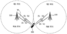
- FIG. 3 is a conceptual diagram illustrating a method for inter-sector cooperative transmission according to an embodiment of the present invention.
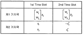
- FIG. 4 illustrates a transmission signal system used in the inter-sector cooperative transmission method shown in FIG.
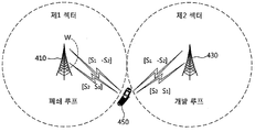
- FIG. 5 is a conceptual diagram illustrating a method for inter-sector cooperative transmission according to another embodiment of the present invention.
- FIG. 6 shows a transmission signal system used in the inter-sector cooperative transmission method shown in FIG.
- FIG. 7 is a flowchart illustrating an example of a communication method to which an inter-sector cooperative transmission method according to an embodiment of the present invention is applied.
- FIG. 8 is a flowchart illustrating another example of a communication method to which an inter-sector cooperative transmission method according to an embodiment of the present invention is applied.
- FIG. 9 is a graph showing a performance evaluation result of the inter-sector cooperative transmission method according to an embodiment of the present invention.
- FIG. 10 is a conceptual diagram illustrating the gain of the inter-sector cooperative transmission method according to an embodiment of the present invention.
- first and second may be used to describe various components, but the components should not be limited by the terms. The terms are used only for the purpose of distinguishing one component from another.
- the first component may be referred to as the second component, and similarly, the second component may also be referred to as the first component.
- terminal used in the present application is a mobile station (MS), a mobile terminal (MT), a user terminal, a user equipment (UE), a user terminal (UT: User Terminal), a wireless terminal, Access Terminal (AT), Subscriber Unit, Subscriber Station (SS), Wireless Device, Wireless Communication Device, Wireless Transmit / Receive Unit (WTRU), Mobile Node, Mobile Or other terms.
- MS mobile station
- MT mobile terminal
- UE user equipment
- UT User Terminal
- AT Access Terminal
- SS Subscriber Unit
- Wireless Device Wireless Communication Device
- WTRU Wireless Transmit / Receive Unit
- the 'base station' used in the present application generally refers to a fixed point for communicating with a terminal, and includes a base station, a Node-B, an eNode-B, and a BTS. It may be called other terms such as (Base Transceiver System), Access Point.
- the inter-sector coMP supporting the terminal located at the cell boundary by using both a closed loop and an open loop scheme Provide a method.
- FIG. 3 is a conceptual diagram illustrating an intersector cooperative transmission method according to an embodiment of the present invention
- FIG. 4 illustrates a transmission signal system used in the intersector cooperative transmission method shown in FIG.
- the first base station 310 and the second base station 330 located in the first sector and the second sector where cell boundaries are adjacent to each other, respectively.
- One terminal transmits data in a beamforming method using a closed loop
- the other terminal transmits data in an Alamouti-code method using an open loop (350) located at a cell boundary. ).
- the first base station 310 of the first sector uses a beamforming scheme
- the second base station 330 of the second sector uses an Alamouti-code scheme, for example.
- the present invention is not limited thereto, and it is apparent that the second base station 330 uses a beamforming method and the first base station 310 may use an Alamouti-code.
- the first base station 310 uses the beamforming vectors w 1 and w 2 to transmit symbol s 1.
- a transmission signal system for transmitting s 2 is shown in FIG. 4.
- the beamforming vectors w 1 and w 2 are vectors that maximize the power of the received signal using the channel state information transmitted from the terminal 350 to the first base station 310 using a closed loop. It can be represented as 1.
- Equation 1 h 1,1 and h 2,1 represent gains generated from the first antenna and the second antenna of the first base station 310, respectively, and h 1,2 and h 2,2 represent the second base station, respectively. Gains generated from the first antenna and the second antenna of 330 are shown. Also, in Equation 1 Is a constant considered to maintain the sum of the powers of the signals transmitted in the first time slot and the second time slot as P, such as the signal power shown in Equation 2.
- the signals r A1 and r A2 received by the terminal 350 in the first reception period and the second reception period, respectively, are represented by Equation 3 below.
- the first reception period refers to a time period during which the terminal receives a signal transmitted by the first and second base stations 310 and 330 in the first time slot
- the second reception period is referred to as the first and second base station ( A time period in which the terminal receives a signal transmitted from the second time slot by 310 or 330.
- n 1 and n 2 denote noise components having Gaussian distributions included in the first and second reception sections, respectively.
- FIG. 5 is a conceptual diagram illustrating an inter-sector cooperative transmission method according to another embodiment of the present invention, and shows an inter-sector cooperative transmission method with reduced decoding complexity compared to the inter-sector cooperative transmission method shown in FIG. 6 shows a transmission signal system used in the inter-sector cooperative transmission method shown in FIG.
- a first base station 410 and a second base station 430 located at first and second sectors whose cell boundaries are adjacent to each other, respectively.
- the method of transmitting data in the Alamouti code method using the open loop is the same as that shown in FIG.
- the first base station 410 of the first sector uses an Alamouti-coded beamforming scheme
- the second base station 430 of the second sector uses an Alamouti-code scheme.
- the second base station 430 may use an Alamouti-coded beamforming scheme
- the first base station 410 may use an Alamouti-code.
- the first base station 410 uses the beamforming vectors w 1 and w 2 to signal s 1 and
- the transmission signal system for transmitting s 2 is shown in FIG. 6.
- the signals r B1 and r B2 received by the terminal 450 in the first reception period and the second reception period may be expressed by Equation 4 below.
- gains generated from the antenna of the first base station 410 and the antenna of the second base station 430, as shown in Equation 5, may be represented by substitution matrices of H 1 and H 2 . Can be.
- Equation 5 H 1 and H 2 may be represented as shown in Equation 6.
- inter-sector cooperative transmission method A' the inter-sector cooperative transmission method according to an embodiment of the present invention shown in FIG. 3 and the inter-sector cooperative operation according to another embodiment of the present invention shown in FIG.
- the complexity of the transmission method (hereinafter referred to as 'inter-sector cooperative transmission method B') is compared.
- a maximum likelihood detection (MLD) method is used as a decoding method of signals transmitted through the inter-sector cooperative transmission method A and the inter-sector cooperative transmission method B, respectively.
- the MLD considers all transmittable symbol vectors, and transmits a transmission vector that minimizes the matrix value represented by Equation 7 from the received signal y and channel gain information h. In this way, the optimal performance is obtained when the transmission probabilities of the transmission symbol vectors are the same.
- the amount of computation required increases exponentially as the number of transmit antennas and the modulation order increase. That is, when the set of symbols on the constellation map used for modulation is M and the number of transmit antennas is N T , the number of matrix operations of the MLD is to be.
- Equation (8) the equation for detecting the transmission signal can be expressed as Equation (8).
- Equation (8) Can be expressed as in Equation 9.
- Equation 10 may be expressed as Equation 10.
- Equation (11) Equation (11).
- the received signals r B1 and r B2 can be separated into s 1 and s 2 , respectively, by using the property that each row is orthogonal in the determinant as shown in Equation 5.
- the received signal of the signal transmitted through the inter-sector cooperative transmission method B enables single symbol decoding when performing MLD, so that the number of matrix operations becomes 2M. Therefore, the inter-sector cooperative transmission method B can reduce the detection complexity even when using multi-level QAM (Multilevel QAM) signals compared to the intersector cooperative transmission method A.
- Multilevel QAM Multilevel QAM
- FIG. 7 is a flowchart illustrating an example of a communication method to which an inter-sector cooperative transmission method is applied according to an embodiment of the present invention. It shows the process of supporting the terminal located at the boundary.
- the UE measures downlink channel state information (step 710) and transmits the measured channel state information to the first base station through the uplink (step 720).
- the first base station calculates a beamforming vector based on the channel state information transmitted from the terminal (step 730).
- the beamforming vectors are w 1 and w 2 .
- the first base station signals the terminal using either the beamforming method of the inter-sector cooperative transmission method A or the beamforming method using the closed loop of the intersectoral cooperative transmission method B based on the calculated beamforming vector. (Step 740). That is, the first base station uses the calculated beamforming vectors w 1 and w 2 to calculate the closed loop beamforming signal system 741 shown in FIG. 4 or the closed loop beamforming signal system 743 shown in FIG. 6. Send the signal using one of the
- the second base station transmits data to the terminal using the Alamouti code in an open loop manner (step 750).
- the terminal receives data transmitted simultaneously from the first base station and the second base station, and detects the transmission data using the MLD (step 760).
- FIG. 8 is a flowchart illustrating another example of a communication method to which the inter-sector cooperative transmission method is applied according to an embodiment of the present invention, and the communication is performed by applying the inter-sector cooperative transmission method A and the inter-sector cooperative transmission method B to the relay system. It shows the process to perform.
- a relay device and a terminal measure downlink channel state information (step 810), and transmit the measured channel state information to a transmitting device through an uplink (step 820).
- the transmitting device may be a base station or another relay device existing between the base station and the relay device.
- the transmitting device calculates a beamforming vector based on the channel state information transmitted from the terminal (step 830).
- the transmitting apparatus uses either the beamforming method of the inter-sector cooperative transmission method A or the beamforming method using the closed loop of the intersectoral cooperative transmission method B based on the calculated beamforming vector and the relay device and the terminal.
- the signal is broadcasted (step 840). That is, the transmitting apparatus uses the calculated beamforming vectors w 1 and w 2 to close loop beamforming signal scheme 841 as shown in FIG. 4 or closed loop beamforming signal scheme as shown in FIG. 6. Send the signal using one of 843.
- the relay device After receiving the signal transmitted from the transmitting device, the relay device transmits the open signal of the inter-sector cooperative transmission method A and the inter-sector cooperative transmission method B described above (that is, transmission using an Alamouti code). Relay to the terminal (step 850).
- the relay device since the relay device transmits a signal using an open loop, the relay device may transmit a signal to the terminal regardless of the relay type (Type 1 or Type2).
- the terminal receives the data transmitted from the transmitting apparatus and the relay apparatus, and detects the transmission data using the MLD (step 860).
- FIG. 9 is a graph showing a performance evaluation result of the inter-sector cooperative transmission method according to an embodiment of the present invention.
- the Rayleigh fading channel is considered, and the moving speeds of the UE located at the cell boundary are 30 km / h (a in FIG. 9) and 120 km / Bit error rate (BER) in case of h (b of FIG. 9) was evaluated.
- BER Bit error rate
- the size of information fed back from the terminal to the base station is limited to a maximum of 4 bits.
- bit error rate is slightly different from that of the conventional cooperative transmission method, but it is assumed that channel estimation is perfect in the simulation process for performance evaluation. Therefore, when considering a realistic environment, the conventional cooperative transmission method will be more affected by channel estimation, which will degrade performance.
- the inter-sector cooperative transmission method A of the present invention has a more complicated detection process in the terminal than the inter-sector cooperative transmission method B, but the BER performance is better.
- FIG. 10 is a conceptual diagram illustrating the gain of the inter-sector cooperative transmission method according to an embodiment of the present invention.
- two base stations 1001-1003, 1001-1005, or 1003-1005 having adjacent cell or sector boundaries use an open loop and a closed loop, respectively.
- a constant gain can always be obtained at a cell or sector boundary regardless of the distance from the base station.
Landscapes
- Engineering & Computer Science (AREA)
- Computer Networks & Wireless Communication (AREA)
- Signal Processing (AREA)
- Mobile Radio Communication Systems (AREA)
Abstract
협력 전송 방법 및 이를 수행하는 협력 전송 시스템이 개시된다. 제1 기지국 및 제1 기지국의 셀 또는 섹터 경계와 인접한 경계를 가지는 제2 기지국을 포함하는 통신 시스템의 협력 전송 방법은, 제1 기지국이 단말로부터 채널 상태 정보를 획득하고, 제1 기지국이 채널 상태 정보에 기초하여 빔포밍 벡터를 산출한 후, 제1 기지국이 빔포밍 벡터에 기초하여 빔포밍으로 신호를 전송하고, 동시에 제2 기지국이 알라무티 코드를 이용하여 신호를 전송하는 한다. 따라서, 셀 전체의 데이터 처리율을 향상시킬 수 있고, 피드백 오버헤드의 감소에 의해 무선 자원의 이용 효율이 향상된다.
Description
본 발명은 무선통신 시스템에 관한 것으로, 더욱 상세하게는 무선통신 시스템에서 협력 전송 방법 및 이를 수행하는 협력 전송 시스템에 관한 것이다.
일반적으로, 섹터의 기지국간(Intra-eNB) 협력 전송(CoMP: Coordinate Multi-Point)은 지리적으로 근접한 거리에 위치한 복수의 섹터 기지국이 광섬유 등으로 서로 연결되고 협력을 통하여 다수의 사용자 단말을 지원하는 방식으로 이루어진다. 상기한 바와 같은 기지국간 협력 전송 환경에서 다수의 사용자 단말은 여러 섹터에 분포되어 있기 때문에 블록 대각화(BD: Block Digonalization)를 사용하여 섹터간 간섭을 줄인다. 또한, 각 섹터에 다수의 사용자 단말이 존재할 경우 단일 벡터 분해(SVD: Single Vector Decomposition)을 사용하여 사용자 단말간의 간섭을 감소시킨다.
도 1은 종래의 기지국간 협력 전송 방법을 나타내는 흐름도이다.
도 1을 참조하면, 먼저 사용자 단말은 하향 링크 채널을 측정하고(단계 10), 측정된 하향 링크 채널 정보를 각 섹터의 기지국으로 전송한다(단계 20).
각 섹터의 기지국은 사용자 단말로부터 전송된 하향 링크 채널 정보에 기초하여 다른 기지국에 미치는 간섭을 최소화하기 위해 빔포밍 벡터를 계산한 후(단계 30), 계산된 빔포밍 벡터를 이용하여 사용자 단말에 협력적으로 신호를 전송한다(단계 40).
도 2는 종래의 기지국간 협력 전송 방법의 이득을 나타내는 개념도이다.
종래의 기지국간 협력 전송 방법은 각 섹터의 기지국(51, 52, 53)이 서로 협력하여 음영 지역에 존재하는 사용자를 지원한다. 그러나, 도 2에 도시한 바와 같이 종래의 기지국간 협력 전송 방법을 통한 이득 지역(60)은 기지국에 근접할수록 이득이 높아지고 기지국으로부터 멀어질수록 이득이 감소하기 때문에 기지국으로부터 멀리 떨어진 위치에 존재하는 사용자 단말은 협력 전송에 의한 이득을 거의 얻을 수 없는 단점이 있다.
또한, 종래의 기지국간 협력 전송 방법에서는 폐쇄루프 방식을 이용하기 때문에 각 기지국들은 사용자 단말로부터 주기적으로 채널 상태 정보를 피드백 받아야 하고, 이와 같은 피드백 정보로 인해 사용자 단말에 상당한 오버헤드가 발생하게 된다. 또한, 종래의 기지국간 협력 전송 방법에서는 사용자 단말로부터 전송된 채널 상태 정보에 기초하여 협력 전송을 수행하기 때문에 협력 전송 효율을 향상시키기 위해서는 채널 상태를 정확하게 추정해야 한다.
상술한 단점을 극복하기 위한 본 발명의 목적은 셀 전체의 데이터 처리율을 향상시킬 수 있고, 오버헤드를 감소시킬 수 있는 협력 전송 방법을 제공하는 것이다.
또한, 본 발명의 다른 목적은 상기 협력 전송 방법을 수행하는 섹터간 협력 전송 시스템을 제공하는 것이다.
상술한 본 발명의 목적을 달성하기 위한 본 발명의 일 측면에 따른 섹터간 협력 전송 방법은, 제1 기지국 및 상기 제1 기지국의 셀 또는 섹터 경계와 인접한 경계를 가지는 제2 기지국을 포함하는 통신 시스템에서, 상기 제1 기지국이 단말로부터 채널 상태 정보를 획득하는 단계와, 상기 제1 기지국이 상기 채널 상태 정보에 기초하여 빔포밍 벡터를 산출하는 단계 및 상기 제1 기지국이 상기 빔포밍 벡터에 기초하여 빔포밍으로 신호를 전송하고, 동시에 상기 제2 기지국이 알라무티 코드를 이용하여 신호를 전송하는 단계를 포함한다. 상기 신호를 전송하는 단계는 상기 제1 및 제2 기지국이 각각 2개의 송신 안테나를 가지는 경우, 제1 타임 슬롯에 상기 제1 기지국은 w1s1, w2s1 신호(여기서, w1 및 w2는 각 안테나의 빔포밍 벡터이고, s1 및 s2는 전송 심볼을 의미함)각 전송하고 상기 제2 기지국은 s1, s2 신호를 전송하며, 상기 제1 타임 슬롯과 연속한 시간인 제2 타임 슬롯에 상기 제1 기지국은 w1s2, w2s2 신호를 전송하고 상기 제2 기지국은 -s2
*, s1
* 신호를 전송할 수 있다. 상기 신호를 전송하는 단계는 상기 제1 및 제2 기지국이 각각 2개의 송신 안테나를 가지는 경우, 제1 타임 슬롯에 상기 제1 기지국은 s1w1, s2w2 신호(여기서, w1 및 w2는 각 안테나의 빔포밍 벡터이고, s1 및 s2는 전송 심볼을 의미함)를 전송하고 상기 제2 기지국은 s1, s2 신호를 전송하며, 상기 제1 타임 슬롯과 연속한 시간인 제2 타임 슬롯에 상기 제1 기지국은 -s2
*w1, s1
*w2 신호를 전송하고 상기 제2 기지국은 -s2
*, s1
* 신호를 전송할 수 있다.
또한, 상술한 본 발명의 목적을 달성하기 위한 본 발명의 다른 측면에 따른 섹터간 협력 전송 방법은, 송신 장치 및 릴레이 장치를 포함하는 통신 시스템의 협력 전송 방법에 있어서, 상기 송신 장치가 단말 및 릴레이 장치 중 적어도 하나의 장치로부터 채널 상태 정보를 획득하는 단계와, 상기 송신 장치가 상기 채널 상태 정보에 기초하여 빔포밍 벡터를 산출하는 단계와, 상기 송신 장치가 상기 빔포밍 벡터에 기초하여 상기 릴레이 장치 및 단말 중 적어도 하나의 장치에 빔포밍으로 신호를 전송하는 단계 및 상기 릴레이 장치가 상기 송신 장치로부터 수신한 신호를 알라무티 코드를 이용하여 상기 단말에 릴레이 하는 단계를 포함한다. 상기 신호를 전송하는 단계는 상기 송신 장치가 2개의 송신 안테나를 가지는 경우, 제1 타임 슬롯에 w1s1, w2s1 신호(여기서, w1 및 w2는 각 안테나의 빔포밍 벡터이고, s1 및 s2는 전송 심볼을 의미함)를 전송하고 상기 제1 타임 슬롯과 연속한 시간인 제2 타임 슬롯에 w1s2, w2s2 신호를 전송하거나, 상기 송신 장치가 상기 제1 타임 슬롯에 s1w1, s2w2 신호를 전송하고 상기 제2 타임 슬롯에 -s2
*w1, s1
*w2 신호를 전송할 수 있다.
또한, 본 발명의 다른 목적을 달성하기 위한 본 발명의 일 측면에 따른 섹터간 협력 전송 시스템은 하향링크의 채널 상태를 판단하고, 판단된 채널 상태 정보를 제공하는 단말과, 상기 단말로부터 전송된 채널 상태 정보에 기초하여 빔포밍 벡터를 산출하고, 산출된 상기 빔포밍 벡터에 기초하여 빔포밍으로 상기 단말에 신호를 전송하는 제1 기지국 및 상기 제1 기지국의 셀 또는 섹터 경계와 인접한 경계를 가지고, 알라무티 코드를 이용하여 상기 제1 기지국과 동시에 상기 단말에 신호를 전송하는 제2 기지국을 포함한다.
상술한 바와 같은 협력 전송 방법 및 이를 수행하는 협력 전송 시스템에 따르면, 제1 기지국이 폐쇄 루프 방식의 빔포밍 또는 알라무티 코드화된 빔포밍으로 신호를 전송하고, 상기 제1 기지국의 셀 또는 섹터 경계와 인접한 경계를 가지는 제2 기지국이 개방 루프 방식의 알라무티 코드를 이용하여 신호를 전송함으로써, 기지국과의 거리에 상관없이 셀 또는 섹터 경계에 위치하는 단말의 데이터 전송 효율을 향상시킬 수 있고, 제2 기지국이 개방 루프 방식으로 신호를 전송함으로써 단말의 피드백 오버헤드를 감소시킬 수 있고, 이를 통해 네트워크 자원을 보다 효율적으로 사용할 수 있다.
도 1은 종래의 기지국간 협력 전송 방법을 나타내는 흐름도이다.
도 2는 종래의 기지국간 협력 전송 방법의 이득을 나타내는 개념도이다.
도 3은 본 발명의 일 실시예에 따른 섹터간 협력 전송 방법을 나타내는 개념도이다.
도 4는 도 3에 도시한 섹터간 협력 전송 방법에서 사용되는 전송신호 체계를 나타낸다.
도 5는 본 발명의 다른 실시예에 따른 섹터간 협력 전송 방법을 나타내는 개념도이다.
도 6은 도 5에 도시한 섹터간 협력 전송 방법에서 사용되는 전송신호 체계를 나타낸다.
도 7은 본 발명의 실시예에 따른 섹터간 협력 전송 방법이 적용된 통신 방법의 일 예를 나타내는 흐름도이다.
도 8은 본 발명의 실시예에 따른 섹터간 협력 전송 방법이 적용된 통신 방법의 다른 예를 나타내는 흐름도이다.
도 9는 본 발명의 실시예에 따른 섹터간 협력 전송 방법의 성능 평가 결과를 나타내는 그래프이다.
도 10은 본 발명의 실시예에 따른 섹터간 협력 전송 방법의 이득을 나타내는 개념도이다.
본 발명은 다양한 변경을 가할 수 있고 여러 가지 실시예를 가질 수 있는 바, 특정 실시예들을 도면에 예시하고 상세한 설명에 상세하게 설명하고자 한다. 그러나, 이는 본 발명을 특정한 실시 형태에 대해 한정하려는 것이 아니며, 본 발명의 사상 및 기술 범위에 포함되는 모든 변경, 균등물 내지 대체물을 포함하는 것으로 이해되어야 한다. 각 도면을 설명하면서 유사한 참조부호를 유사한 구성요소에 대해 사용하였다.
제1, 제2 등의 용어는 다양한 구성요소들을 설명하는데 사용될 수 있지만, 상기 구성요소들은 상기 용어들에 의해 한정되어서는 안 된다. 상기 용어들은 하나의 구성요소를 다른 구성요소로부터 구별하는 목적으로만 사용된다. 예를 들어, 본 발명의 권리 범위를 벗어나지 않으면서 제1 구성요소는 제2 구성요소로 명명될 수 있고, 유사하게 제2 구성요소도 제1 구성요소로 명명될 수 있다. 및/또는 이라는 용어는 복수의 관련된 기재된 항목들의 조합 또는 복수의 관련된 기재된 항목들 중의 어느 항목을 포함한다.
어떤 구성요소가 다른 구성요소에 "연결되어" 있다거나 "접속되어"있다고 언급된 때에는, 그 다른 구성요소에 직접적으로 연결되어 있거나 또는 접속되어 있을 수도 있지만, 중간에 다른 구성요소가 존재할 수도 있다고 이해되어야 할 것이다. 반면에, 어떤 구성요소가 다른 구성요소에 "직접 연결되어"있다거나 "직접 접속되어"있다고 언급된 때에는, 중간에 다른 구성요소가 존재하지 않는 것으로 이해되어야 할 것이다.
본 출원에서 사용한 용어는 단지 특정한 실시예를 설명하기 위해 사용된 것으로, 본 발명을 한정하려는 의도가 아니다. 단수의 표현은 문맥상 명백하게 다르게 뜻하지 않는 한, 복수의 표현을 포함한다. 본 출원에서, "포함하다" 또는 "가지다" 등의 용어는 명세서상에 기재된 특징, 숫자, 단계, 동작, 구성요소, 부품 또는 이들을 조합한 것이 존재함을 지정하려는 것이지, 하나 또는 그 이상의 다른 특징들이나 숫자, 단계, 동작, 구성요소, 부품 또는 이들을 조합한 것들의 존재 또는 부가 가능성을 미리 배제하지 않는 것으로 이해되어야 한다.
본 출원에서 사용하는 '단말'은 이동국(MS: Mobile Station), 이동 단말(MT: Mobile Terminal), 사용자 단말, 사용자 장비(UE: User Equipment), 사용자 터미널(UT: User Terminal), 무선 터미널, 액세스 터미널(AT), 가입자 유닛(Subscriber Unit), 가입자 스테이션(SS: Subscriber Station), 무선 기기(Wireless device), 무선 통신 디바이스, 무선송수신유닛(WTRU: Wireless Transmit/Receive Unit), 이동 노드, 모바일 또는 다른 용어들로 지칭될 수 있다.
또한, 본 출원에서 사용하는 '기지국'은 일반적으로 단말과 통신하는 고정된 지점을 말하며, 베이스 스테이션(Base Station), 노드-B(Node-B), e노드-B(eNode-B), BTS(Base Transceiver System), 액세스 포인트(Access Point) 등 다른 용어로 불릴 수 있다.
이하, 첨부한 도면들을 참조하여, 본 발명의 바람직한 실시예를 보다 상세하게 설명하고자 한다. 이하, 도면상의 동일한 구성요소에 대해서는 동일한 참조부호를 사용하고 동일한 구성요소에 대해서 중복된 설명은 생략한다.
본 발명의 실시예에 따른 섹터간 협력 전송 방법에서는 폐쇄 루프(Close loop) 방식 및 개방 루프(Open Loop) 방식을 모두 이용하여 셀 경계에 위치한 단말을 지원하는 섹터간 협력 전송(Inter-Sector CoMP) 방법을 제공한다.
도 3은 본 발명의 일 실시예에 따른 섹터간 협력 전송 방법을 나타내는 개념도이고, 도 4는 도 3에 도시한 섹터간 협력 전송 방법에서 사용되는 전송신호 체계를 나타낸다.
도 3 및 도 4를 참조하면, 본 발명의 일 실시예에 따른 섹터간 협력 전송 방법에서는 셀 경계가 서로 인접한 제1 섹터 및 제2 섹터에 각각 위치한 제1 기지국(310)과 제2 기지국(330)이 하나는 폐쇄 루프를 사용하여 빔포밍(Beamforming) 방식으로 데이터를 전송하고, 다른 하나는 개방 루프를 사용하여 알라무티 코드(Alamouti-code) 방식으로 데이터를 전송함으로써 셀 경계에 위치한 단말(350)을 지원한다.
도 3에서는 설명의 편의를 위하여 제1 섹터의 제1 기지국(310)이 빔포밍 방식을 사용하고, 제2 섹터의 제2 기지국(330)이 알라무티-코드 방식을 사용하는 것으로 예를 들어 도시하였으나 여기에 한정되는 것은 아니며, 제2 기지국(330)이 빔포밍 방식을 사용하고, 제1 기지국(310)이 알라무티-코드를 사용할 수 있음은 자명하다.
제1 기지국(310) 및 제2 기지국(330)이 각각 두 개의 송신 안테나를 구비한 것으로 가정하면, 제1 기지국(310)이 빔포밍 벡터(w1, w2)를 사용하여 전송 심볼 s1 및 s2를 전송하는 전송신호 체계는 도 4와 같다.
도 4에서 빔포밍 벡터(w1, w2)는 폐쇄 루프를 사용하여 단말(350)로부터 제1 기지국(310)에 전송된 채널 상태 정보를 이용한 수신 신호의 전력을 최대로 만드는 벡터로서 수학식 1과 같이 나타낼 수 있다.
수학식 1 
수학식 1에서 h1,1 및 h2,1은 각각 제1 기지국(310)의 제1 안테나와 제2 안테나로부터 발생하는 이득을 나타내고, h1,2 및 h2,2는 각각 제2 기지국(330)의 제1 안테나와 제2 안테나로부터 발생하는 이득을 나타낸다. 또한, 수학식 1에서 는 수학식 2에 표시한 신호 전력과 같이 첫 번째 타임 슬롯과 두 번째 타임 슬롯에서 전송되는 신호의 전력의 합을 P로 유지하기 위해 고려되는 상수이다.
수학식 2 
단말(350)이 첫 번째 수신 구간 및 두 번째 수신 구간에서 각각 수신한 신호(rA1, rA2)는 수학식 3과 같다. 여기서, 첫 번째 수신 구간은 제1 및 제2 기지국(310, 330)이 첫 번째 타임 슬롯에서 전송한 신호를 단말이 수신하는 시간 구간을 의미하며, 두 번째 수신 구간은 제1 및 제2 기지국(310, 330)이 두 번째 타임 슬롯에서 전송한 신호를 단말이 수신하는 시간 구간을 의미한다.
수학식 3 
수학식 3에서, n1 및 n2는 각각 첫 번째 수신 구간 및 두 번째 수신 구간에서 포함된 가우시안 분포를 가지는 잡음 성분을 의미한다.
도 3에 도시한 바와 같은 본 발명의 일 실시예에 따른 섹터간 협력 전송 방법에서는 수신한 심볼을 각각 분리한 복호화(Single-symbol decode)를 수행할 수 없기 때문에 복호화의 복잡도가 높다.
도 5는 본 발명의 다른 실시예에 따른 섹터간 협력 전송 방법을 나타내는 개념도로서, 도 3에 도시한 섹터간 협력 전송 방법에 비해 복호화 복잡도를 감소시킨 섹터간 협력 전송 방법을 나타낸다. 도 6은 도 5에 도시한 섹터간 협력 전송 방법에서 사용되는 전송신호 체계를 나타낸다.
도 5 및 도 6을 참조하면, 본 발명의 다른 실시예에 따른 섹터간 협력 전송 방법에서는 셀 경계가 서로 인접한 제1 섹터 및 제2 섹터에 각각 위치한 제1 기지국(410)과 제2 기지국(430)이 하나는 폐쇄 루프를 사용하여 알라무티 코드화된 빔포밍(Beamforming) 방식으로 데이터를 전송하고, 다른 하나는 개방 루프를 사용하여 알라무티 코드(Alamouti-code) 방식으로 데이터를 전송함으로써 셀 경계에 위치한 단말(450)을 지원한다. 여기서, 개방 루프를 사용하여 알라무티 코드 방식으로 데이터를 전송하는 방식은 도 3에 도시한 바와 동일하다.
도 5에서는 설명의 편의를 위하여 제1 섹터의 제1 기지국(410)이 알라무티 코드화된 빔포밍 방식을 사용하고, 제2 섹터의 제2 기지국(430)이 알라무티-코드 방식을 사용하는 것으로 예를 들어 도시하였으나 여기에 한정되는 것은 아니며, 제2 기지국(430)이 알라무티 코드화된 빔포밍 방식을 사용하고, 제1 기지국(410)이 알라무티-코드를 사용할 수 있음은 자명하다.
제1 기지국(410) 및 제2 기지국(430)이 각각 두 개의 송신 안테나를 구비한 것으로 가정하면, 제1 기지국(410)이 빔포밍 벡터(w1, w2)를 사용하여 신호 s1 및 s2를 전송하는 전송신호 체계는 도 6과 같다.
단말(450)이 첫 번째 수신 구간 및 두 번째 수신 구간에서 각각 수신한 신호(rB1, rB2)는 수학식 4와 같이 표현할 수 있다.
수학식 4 
수학식 4에 표시한 수신 신호를 정리하면, 수학식 5와 같이 제1 기지국(410)의 안테나 및 제2 기지국(430)의 안테나로부터 발생하는 이득을 H1 및 H2의 대체 행렬로 표시할 수 있다.
수학식 5 
수학식 5에서 H1 및 H2는 수학식 6과 같이 나타낼 수 있다.
수학식 6 
이하, 도 3에 도시한 본 발명의 일 실시예에 따른 섹터간 협력 전송 방법(이하 '섹터간 협력 전송 방법 A'이라 지칭함)과 도 5에 도시한 본 발명의 다른 실시예에 따른 섹터간 협력 전송 방법(이하, '섹터간 협력 전송 방법 B'라 지칭함)의 복잡도를 비교한다.
먼저, 섹터간 협력 전송 방법 A 및 섹터간 협력 전송 방법 B를 통해 각각 전송된 신호의 복호 방법으로 최대 우도 검출(MLD: Maximum Likelihood Detection) 방법이 사용되는 것으로 가정한다. MLD는 송신 가능한 심볼 벡터들을 모두 고려하여 수신신호 y와 채널 이득 정보인 h로부터 수학식 7로 표현되는 행렬 값을 최소로 하는 송신 벡터 를 검출하는 방식으로, 송신 심볼 벡터의 전송 확률이 모두 같을 때 최적의 성능을 나타낸다.
수학식 7 
그러나, MLD는 송신 안테나의 수와 변조 차수(modulation order)가 증가함에 따라 소요되는 계산량이 지수 함수적으로 증가하게 된다. 즉, 변조를 위해 사용되는 성상도(Constellation map) 상의 심볼들의 집합이 M개이고, 송신 안테나의 개수가 NT개 일 때, MLD의 행렬 연산 회수는  이다.
이다.
섹터간 협력 전송 방법 A를 사용할 때 송신 신호의 검출 결정을 위한 수학식은 수학식 8과 같이 표현할 수 있다.
수학식 8 
수학식 8에서  는 수학식 9와 같이 나타낼 수 있다.
수학식 9 
섹터간 협력 전송 방법 A를 통해 전송된 신호의 수신 신호 rA1 및 rA2에서 s1과 s2는 서로 분리가 불가능하기 때문에 검출을 위해서는 모든 가능한 s1과 s2의 신호를 수학식 9에 대입해야 한다. 따라서, 섹터간 협력 전송 방법 A에서 M개의 성상도 상의 심볼을 사용하였다면 MLD를 위한 행렬 연산 회수는 M2으로 표현할 수 있고, 변조 차수가 높을수록 검출을 위한 복잡도가 더욱 증가하게 된다.
한편, 섹터간 협력 전송 방법 B의 경우에는 MLD를 사용하는 경우 수학식 10과 같이 표현할 수 있고, 수학식 10에서 는 수학식 11과 같이 나타낼 수 있다.
수신 신호 rB1 및 rB2는 수학식 5에 표시한 바와 같이 행렬식에서 각 행이 직교하는 성질을 이용하여 각각 s1과 s2로 분리할 수 있다.
수학식 10 
수학식 11 
섹터간 협력 전송 방법 B를 통해 전송된 신호의 수신 신호는 MLD를 수행할 때 단일 심볼 복호화가 가능하게 되어 행렬 연산 회수는 2M이 된다. 따라서, 섹터간 협력 전송 방법 B는 섹터간 전송 협력 전송 방법 A에 비해 여러 단계의 QAM(Multilevel QAM) 신호를 사용하는 경우에도 검출 복잡도를 감소시킬 수 있다.
도 7은 본 발명의 실시예에 따른 섹터간 협력 전송 방법이 적용된 통신 방법의 일 예를 나타내는 흐름도로서, 상술한 섹터간 협력 전송 방법 A 및 섹터간 협력 전송 방법 B를 이용하여 두 섹터 기지국이 셀 경계에 위치한 단말을 지원하는 과정을 나타낸다.
도 7을 참조하면, 먼저 단말은 하향 링크의 채널 상태 정보를 측정하고(단계 710), 측정된 채널 상태 정보를 상향 링크를 통해 제1 기지국에 전송한다(단계 720).
제1 기지국은 단말로부터 전송된 채널 상태 정보에 기초하여 빔포밍 벡터를 계산한다(단계 730). 여기서, 제1 기지국의 송신 안테나가 2개인 것으로 가정하면 빔포밍 벡터는 w1 및 w2가 된다.
이후, 제1 기지국은 계산된 빔포밍 벡터에 기초하여 상술한 섹터간 협력 전송 방법 A의 빔포밍 방법 및 섹터간 협력 전송 방법 B의 폐쇄 루프를 이용한 빔포밍 방법 중 어느 하나를 이용하여 단말에 신호를 전송한다(단계 740). 즉, 제1 기지국은 계산된 빔포밍 벡터 (w1, w2)를 이용하여 도 4에 도시한 폐쇄 루프 빔포밍 신호 체계(741) 또는 도 6에 도시한 폐쇄 루프 빔포밍 신호 체계(743) 중 하나를 사용하여 신호를 전송한다.
이와 동시에, 제2 기지국은 개방 루프 방식으로 알라무티 코드를 이용하여 단말에 데이터를 전송한다(단계 750).
단말은 제1 기지국 및 제2 기지국으로부터 동시에 전송된 데이터를 수신하고, MLD를 이용하여 전송 데이터를 검출한다(단계 760).
도 8은 본 발명의 실시예에 따른 섹터간 협력 전송 방법이 적용된 통신 방법의 다른 예를 나타내는 흐름도로서, 릴레이 시스템에 상술한 섹터간 협력 전송 방법 A 및 섹터간 협력 전송 방법 B를 적용하여 통신을 수행하는 과정을 나타낸다.
도 8을 참조하면, 먼저 릴레이 장치 및 단말이 하향 링크의 채널 상태 정보를 측정하고(단계 810), 측정된 채널 상태 정보를 상향 링크를 통해 송신 장치로 전송한다(단계 820). 여기서, 송신 장치는 기지국이 될 수도 있고, 기지국과 상기 릴레이 장치 사이에 존재하는 다른 릴레이 장치가 될 수도 있다.
송신 장치는 단말로부터 전송된 채널 상태 정보에 기초하여 빔포밍 벡터를 계산한다(단계 830).
이후, 송신 장치는 계산된 빔포밍 벡터에 기초하여 상술한 섹터간 협력 전송 방법 A의 빔포밍 방법 및 섹터간 협력 전송 방법 B의 폐쇄 루프를 이용한 빔포밍 방법 중 어느 하나를 이용하여 릴레이 장치 및 단말에 신호를 방송한다(단계 840). 즉, 송신 장치는 계산된 빔포밍 벡터 (w1, w2)를 이용하여 도 4에 도시한 바와 같은 폐쇄 루프 빔포밍 신호 체계(841) 또는 도 6에 도시한 바와 같은 폐쇄 루프 빔포밍 신호 체계(843) 중 하나를 사용하여 신호를 전송한다.
릴레이 장치는 송신 장치로부터 전송된 신호를 수신한 후, 수신된 신호를 상술한 섹터간 협력 전송 방법 A 및 섹터간 협력 전송 방법 B의 개방 루프를 전송 방법(즉, 알라무티 코드를 이용한 전송)을 이용하여 단말에 릴레이 한다(단계 850). 여기서, 릴레이 장치는 개방 루프를 이용하여 신호를 전송하기 때문에 릴레이 유형(Type 1 또는 Type2)에 상관없이 단말에 신호를 전송할 수 있다.
단말은 송신 장치 및 릴레이 장치로부터 전송된 데이터를 수신하고, MLD를 이용하여 전송 데이터를 검출한다(단계 860).
도 9는 본 발명의 실시예에 따른 섹터간 협력 전송 방법의 성능 평가 결과를 나타내는 그래프이다.
본 발명의 실시예에 따른 섹터간 협력 전송 방법의 성능 평가에는 레일레이 페이딩(Rayleigh fading) 채널이 고려되었으며, 셀 경계에 위치한 단말의 이동 속도가 각각 30km/h(도 9의 a)와 120km/h(도 9의 b)인 경우의 비트에러율(BER: Bit Error Rate)을 평가하였다. 또한, 정확한 성능 평가를 위하여 폐쇄 루프를 이용하는 경우 단말로부터 기지국으로 피드백되는 정보의 크기는 최대 4비트로 제한하였다.
도 9에 도시한 바와 같이 본 발명의 실시예에 따른 섹터간 협력 전송 방법은 종래의 협력 전송 방법에 비해 비트 에러율은 다소 차이가 있으나, 성능 평가를 위한 모의 실험 과정에서 채널 추정이 완벽한 것으로 가정하였기 때문에 현실적인 환경을 고려하는 경우 종래의 협력 전송 방법은 채널 추정에 더 많은 영향을 받게 되어 성능이 열화될 것이다.
즉, 현실적인 통신 환경에서는 개방 루프 및 폐쇄 루프를 모두 사용하는 본 발명의 섹터간 협력 통신 방법이 종래의 협력 통신 방법 보다 더 좋은 성능을 가질 것으로 예상된다.
또한, 도 9에 도시한 바와 같이 본 발명의 섹터간 협력 전송 방법 A는 섹터간 협력 전송 방법 B에 비하여 단말에서에서 검출 과정이 더 복잡하나, BER 성능이 더 좋음을 알 수 있다.
도 10은 본 발명의 실시예에 따른 섹터간 협력 전송 방법의 이득을 나타내는 개념도이다.
도 10에 도시한 바와 같이 본 발명의 실시예에 따른 섹터간 협력 전송 방법은 셀 또는 섹터 경계가 인접한 두 기지국(1001-1003, 1001-1005 또는 1003-1005)이 각각 개방 루프 및 폐쇄 루프를 사용하여 신호를 전송함으로써, 기지국과의 거리에 상관없이 셀 또는 섹터 경계에서 항상 일정한 이득을 얻을 수 있다.
이상, 본 발명을 바람직한 실시예를 들어 상세하게 설명하였으나, 본 발명은 상기 실시예에 한정되지 않고, 본 발명의 기술적 사상 및 범위 내에서 당 분야에서 통상의 지식을 가진 자에 의하여 여러가지 변형 및 변경이 가능하다.
Claims (8)
- 제1 기지국 및 상기 제1 기지국의 셀 또는 섹터 경계와 인접한 경계를 가지는 제2 기지국을 포함하는 통신 시스템의 협력 전송 방법에 있어서,상기 제1 기지국이 단말로부터 채널 상태 정보를 획득하는 단계;상기 제1 기지국이 상기 채널 상태 정보에 기초하여 빔포밍 벡터를 산출하는 단계; 및상기 제1 기지국이 상기 빔포밍 벡터에 기초하여 빔포밍으로 신호를 전송하고, 동시에 상기 제2 기지국이 알라무티 코드를 이용하여 신호를 전송하는 단계를 포함하는 협력 통신 방법.
- 제1항에 있어서, 상기 신호를 전송하는 단계는상기 제1 및 제2 기지국이 각각 2개의 송신 안테나를 가지는 경우, 제1 타임 슬롯에 상기 제1 기지국은 w1s1, w2s1 신호(여기서, w1 및 w2는 각 안테나의 빔포밍 벡터이고, s1 및 s2는 전송 심볼을 의미함)각 전송하고 상기 제2 기지국은 s1, s2 신호를 전송하며, 상기 제1 타임 슬롯과 연속한 시간인 제2 타임 슬롯에 상기 제1 기지국은 w1s2, w2s2 신호를 전송하고 상기 제2 기지국은 -s2 *, s1 * 신호를 전송하는 것을 특징으로 하는 협력 통신 방법.
- 제1항에 있어서, 상기 신호를 전송하는 단계는상기 제1 및 제2 기지국이 각각 2개의 송신 안테나를 가지는 경우, 제1 타임 슬롯에 상기 제1 기지국은 s1w1, s2w2 신호(여기서, w1 및 w2는 각 안테나의 빔포밍 벡터이고, s1 및 s2는 전송 심볼을 의미함)를 전송하고 상기 제2 기지국은 s1, s2 신호를 전송하며, 상기 제1 타임 슬롯과 연속한 시간인 제2 타임 슬롯에 상기 제1 기지국은 -s2 *w1, s1 *w2 신호를 전송하고 상기 제2 기지국은 -s2 *, s1 * 신호를 전송하는 것을 특징으로 하는 협력 통신 방법.
- 송신 장치 및 릴레이 장치를 포함하는 통신 시스템의 협력 전송 방법에 있어서,상기 송신 장치가 단말 및 릴레이 장치 중 적어도 하나의 장치로부터 채널 상태 정보를 획득하는 단계;상기 송신 장치가 상기 채널 상태 정보에 기초하여 빔포밍 벡터를 산출하는 단계;상기 송신 장치가 상기 빔포밍 벡터에 기초하여 상기 릴레이 장치 및 단말 중 적어도 하나의 장치에 빔포밍으로 신호를 전송하는 단계; 및상기 릴레이 장치가 상기 송신 장치로부터 수신한 신호를 알라무티 코드를 이용하여 상기 단말에 릴레이 하는 단계를 포함하는 협력 통신 방법.
- 제4항에 있어서, 상기 신호를 전송하는 단계는상기 송신 장치가 2개의 송신 안테나를 가지는 경우, 제1 타임 슬롯에 w1s1, w2s1 신호(여기서, w1 및 w2는 각 안테나의 빔포밍 벡터이고, s1 및 s2는 전송 심볼을 의미함)를 전송하고 상기 제1 타임 슬롯과 연속한 시간인 제2 타임 슬롯에 w1s2, w2s2 신호를 전송하거나, 상기 송신 장치가 상기 제1 타임 슬롯에 s1w1, s2w2 신호를 전송하고 상기 제2 타임 슬롯에 -s2 *w1, s1 *w2 신호를 전송하는 것을 특징으로 하는 협력 통신 방법.
- 하향링크의 채널 상태를 판단하고, 판단된 채널 상태 정보를 제공하는 단말;상기 단말로부터 전송된 채널 상태 정보에 기초하여 빔포밍 벡터를 산출하고, 산출된 상기 빔포밍 벡터에 기초하여 빔포밍으로 상기 단말에 신호를 전송하는 제1 기지국; 및상기 제1 기지국의 셀 또는 섹터 경계와 인접한 경계를 가지고, 알라무티 코드를 이용하여 상기 제1 기지국과 동시에 상기 단말에 신호를 전송하는 제2 기지국을 포함하는 협력 전송 시스템.
- 제6항에 있어서,상기 제1 및 제2 기지국이 각각 2개의 송신 안테나를 가지는 경우, 제1 타임 슬롯에 상기 제1 기지국은 w1s1, w2s1 신호(여기서, w1 및 w2는 각 안테나의 빔포밍 벡터이고, s1 및 s2는 전송 심볼을 의미함)각 전송하고 상기 제2 기지국은 s1, s2 신호를 전송하며, 상기 제1 타임 슬롯과 연속한 시간인 제2 타임 슬롯에 상기 제1 기지국은 w1s2, w2s2 신호를 전송하고 상기 제2 기지국은 -s2 *, s1 * 신호를 전송하는 것을 특징으로 하는 협력 전송 시스템.
- 제6항에 있어서,상기 제1 및 제2 기지국이 각각 2개의 송신 안테나를 가지는 경우, 제1 타임 슬롯에 상기 제1 기지국은 s1w1, s2w2 신호(여기서, w1 및 w2는 각 안테나의 빔포밍 벡터이고, s1 및 s2는 전송 심볼을 의미함)를 전송하고 상기 제2 기지국은 s1, s2 신호를 전송하며, 상기 제1 타임 슬롯과 연속한 시간인 제2 타임 슬롯에 상기 제1 기지국은 -s2 *w1, s1 *w2 신호를 전송하고 상기 제2 기지국은 -s2 *, s1 * 신호를 전송하는 것을 특징으로 하는 협력 전송 시스템.
Applications Claiming Priority (2)
| Application Number | Priority Date | Filing Date | Title |
|---|---|---|---|
| KR10-2011-0016099 | 2011-02-23 | ||
| KR1020110016099A KR101206607B1 (ko) | 2011-02-23 | 2011-02-23 | 섹터간 협력 전송 방법 및 이를 수행하는 섹터간 협력 전송 시스템 |
Publications (1)
| Publication Number | Publication Date |
|---|---|
| WO2012115326A1 true WO2012115326A1 (ko) | 2012-08-30 |
Family
ID=46721077
Family Applications (1)
| Application Number | Title | Priority Date | Filing Date |
|---|---|---|---|
| PCT/KR2011/008257 Ceased WO2012115326A1 (ko) | 2011-02-23 | 2011-11-01 | 협력 전송 방법 및 이를 수행하는 협력 전송 시스템 |
Country Status (2)
| Country | Link |
|---|---|
| KR (1) | KR101206607B1 (ko) |
| WO (1) | WO2012115326A1 (ko) |
Families Citing this family (1)
| Publication number | Priority date | Publication date | Assignee | Title |
|---|---|---|---|---|
| CN103959677B (zh) * | 2012-11-27 | 2017-04-19 | 华为技术有限公司 | 通信的方法、装置和系统 |
Citations (2)
| Publication number | Priority date | Publication date | Assignee | Title |
|---|---|---|---|---|
| US20100285792A1 (en) * | 2009-05-06 | 2010-11-11 | Runhua Chen | Coordinated Multi-Point Transmission in a Cellular Network |
| US20110013710A1 (en) * | 2009-07-16 | 2011-01-20 | Futurewei Technologies, Inc. | System and Method for Information Feedback in a Wireless Communications System with Coordinated Multiple Point Transmission |
Family Cites Families (1)
| Publication number | Priority date | Publication date | Assignee | Title |
|---|---|---|---|---|
| WO2006047909A1 (en) | 2004-11-04 | 2006-05-11 | Huawei Technologies Co., Ltd. | Method for improving the performance of multiple input multiple output transmit diversity using feedback |
-
2011
- 2011-02-23 KR KR1020110016099A patent/KR101206607B1/ko not_active Expired - Fee Related
- 2011-11-01 WO PCT/KR2011/008257 patent/WO2012115326A1/ko not_active Ceased
Patent Citations (2)
| Publication number | Priority date | Publication date | Assignee | Title |
|---|---|---|---|---|
| US20100285792A1 (en) * | 2009-05-06 | 2010-11-11 | Runhua Chen | Coordinated Multi-Point Transmission in a Cellular Network |
| US20110013710A1 (en) * | 2009-07-16 | 2011-01-20 | Futurewei Technologies, Inc. | System and Method for Information Feedback in a Wireless Communications System with Coordinated Multiple Point Transmission |
Non-Patent Citations (1)
| Title |
|---|
| ZIJIA HWANG ET AL.: "Coordinate Beamforming of CoMP with Limited Feedback.", NETWORK COMPUTING AND INFORMATION SECURITY(NCIS), 2011, INTERNATIONAL CONFERENCE ON, vol. 1, 14 May 2011 (2011-05-14), pages 138 - 141 * |
Also Published As
| Publication number | Publication date |
|---|---|
| KR20120096789A (ko) | 2012-08-31 |
| KR101206607B1 (ko) | 2012-11-29 |
Similar Documents
| Publication | Publication Date | Title |
|---|---|---|
| WO2016036226A1 (en) | Method and apparatus for channel-related information feedback in a beamforming system | |
| WO2019156512A1 (en) | Method and apparatus for wideband csi reporting in an advanced wireless communication system | |
| WO2010147346A2 (en) | Method of minimizing feedback overhead using spatial channel covariance in a multi-input multi-output system | |
| WO2013015664A2 (en) | Apparatus and method for combining baseband processing and radio frequency beam steering in a wireless communication system | |
| WO2013100579A1 (en) | Channel state information feedback apparatus and method in wireless communication system operating in fdd mode | |
| WO2011087280A2 (en) | Method for generating preamble in multi-user multi-input multi-output system, and data transmission apparatus and user terminal using the method | |
| WO2010150950A1 (en) | Method of performing link adaptation procedure | |
| WO2016039586A1 (ko) | 무선 통신 시스템에서 기준 신호를 송수신하는 기법 | |
| WO2018155884A1 (ko) | 무선 통신 시스템에서 보안 키를 생성하기 위한 장치 및 방법 | |
| WO2011099714A2 (en) | Multiple input multiple output communication method and system for exchanging coordinated rank information for neighbor cell | |
| WO2017026762A1 (ko) | 이동 통신 시스템에서 csi-rs를 이용하는 통신 기법 | |
| WO2010095824A2 (ko) | 조정 다지점 송신을 통한 데이터 통신 방법 및 장치 | |
| WO2016013698A1 (ko) | 피드백 신호를 전송하는 방법 및 장치 | |
| WO2016175609A1 (ko) | 무선 통신 시스템에서 하향링크 채널 추정 장치 및 방법 | |
| WO2011053066A2 (en) | Calibration apparatus and method for multicell multiple input multiple output transmission in multiple antenna system | |
| WO2013115601A1 (en) | Interference alignment method and apparatus in wireless communication system | |
| WO2010024539A2 (en) | Method and transmitter for iteratively modifying beamforming vector | |
| WO2018070853A1 (ko) | 무선 셀룰러 통신 시스템에서 네트워크 지원 간섭 제거 및 억제를 위한 방법 및 장치 | |
| WO2016159597A1 (en) | Method and apparatus for transmitting signal using sliding-window superposition coding in wireless network | |
| WO2011049380A9 (ko) | 공간다중화 시스템에서 신호검출 장치 및 방법 | |
| WO2016195334A1 (ko) | Mimo 기반 빔포밍을 지원하는 통신 시스템에서 채널을 추정하는 방법 및 장치 | |
| WO2010074523A2 (ko) | 빔포밍을 위한 가중치 행렬 결정 방법 및 장치 | |
| WO2010114341A2 (ko) | 다중 셀 통신 시스템에서 셀 가장자리 사용자의 에러를 최소화하기 위한 장치 및 방법 | |
| WO2010068039A2 (ko) | 멀티 인풋 멀티 아웃풋 시스템의 제어 정보 송수신 방법 및 장치 | |
| EP3895328A1 (en) | Methods and systems for adapting beamwidth of beams on nr physical channels |
Legal Events
| Date | Code | Title | Description |
|---|---|---|---|
| 121 | Ep: the epo has been informed by wipo that ep was designated in this application |
Ref document number: 11859493 Country of ref document: EP Kind code of ref document: A1 |
|
| NENP | Non-entry into the national phase |
Ref country code: DE |
|
| 122 | Ep: pct application non-entry in european phase |
Ref document number: 11859493 Country of ref document: EP Kind code of ref document: A1 |