WO2012115046A1 - 光学情報読取装置、光学情報読取方法、コンピュータが読み取り可能なプログラム及び記録媒体 - Google Patents
光学情報読取装置、光学情報読取方法、コンピュータが読み取り可能なプログラム及び記録媒体 Download PDFInfo
- Publication number
- WO2012115046A1 WO2012115046A1 PCT/JP2012/053992 JP2012053992W WO2012115046A1 WO 2012115046 A1 WO2012115046 A1 WO 2012115046A1 JP 2012053992 W JP2012053992 W JP 2012053992W WO 2012115046 A1 WO2012115046 A1 WO 2012115046A1
- Authority
- WO
- WIPO (PCT)
- Prior art keywords
- character
- width
- data
- bar
- space
- Prior art date
- Legal status (The legal status is an assumption and is not a legal conclusion. Google has not performed a legal analysis and makes no representation as to the accuracy of the status listed.)
- Ceased
Links
Images


Classifications
-
- G—PHYSICS
- G06—COMPUTING OR CALCULATING; COUNTING
- G06K—GRAPHICAL DATA READING; PRESENTATION OF DATA; RECORD CARRIERS; HANDLING RECORD CARRIERS
- G06K7/00—Methods or arrangements for sensing record carriers, e.g. for reading patterns
- G06K7/10—Methods or arrangements for sensing record carriers, e.g. for reading patterns by electromagnetic radiation, e.g. optical sensing; by corpuscular radiation
- G06K7/14—Methods or arrangements for sensing record carriers, e.g. for reading patterns by electromagnetic radiation, e.g. optical sensing; by corpuscular radiation using light without selection of wavelength, e.g. sensing reflected white light
- G06K7/1404—Methods for optical code recognition
- G06K7/146—Methods for optical code recognition the method including quality enhancement steps
- G06K7/1486—Setting the threshold-width for bar codes to be decoded
-
- G—PHYSICS
- G06—COMPUTING OR CALCULATING; COUNTING
- G06K—GRAPHICAL DATA READING; PRESENTATION OF DATA; RECORD CARRIERS; HANDLING RECORD CARRIERS
- G06K5/00—Methods or arrangements for verifying the correctness of markings on a record carrier; Column detection devices
-
- G—PHYSICS
- G06—COMPUTING OR CALCULATING; COUNTING
- G06K—GRAPHICAL DATA READING; PRESENTATION OF DATA; RECORD CARRIERS; HANDLING RECORD CARRIERS
- G06K7/00—Methods or arrangements for sensing record carriers, e.g. for reading patterns
- G06K7/10—Methods or arrangements for sensing record carriers, e.g. for reading patterns by electromagnetic radiation, e.g. optical sensing; by corpuscular radiation
- G06K7/14—Methods or arrangements for sensing record carriers, e.g. for reading patterns by electromagnetic radiation, e.g. optical sensing; by corpuscular radiation using light without selection of wavelength, e.g. sensing reflected white light
- G06K7/1404—Methods for optical code recognition
- G06K7/1408—Methods for optical code recognition the method being specifically adapted for the type of code
- G06K7/1413—1D bar codes
Definitions
- the present invention relates to an optical information reading apparatus, an optical information reading method, a computer readable program, and a recording medium that can be applied to a bar code symbol reading apparatus that reads bar code symbols and outputs bar code data.
- bar code symbol standards include CODE128, CODE39, EAN / UPC (EAN / Universal Product Code), interleaved 2 of 5, coder bar, RSS, RSS Limited, RSS Expanded, and the like.
- a barcode symbol is often used by attaching a barcode symbol mark to a distribution article or directly printing it on a package.
- the bar code symbol affixed or printed on the distribution article cannot be read correctly due to variations in these printing techniques, sticking techniques, etc., or the handling method of the distribution article.
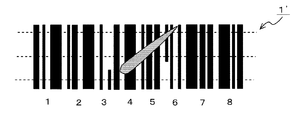
- the reason why the bar code symbol cannot be read correctly includes missing bars and spaces constituting the bar code symbol, scratches, and the like.
- Patent Document 1 discloses a barcode symbol reading apparatus, a start margin candidate detection method and a barcode symbol reading method using the barcode symbol reading apparatus.
- the barcode symbol reader is applied to decode a difficult-to-read character including a missing or scratched unintentionally generated in a bar or space constituting the barcode symbol.
- FIG. 14 is a block diagram showing a configuration example of the optical information reading apparatus 20 according to the conventional example.
- 14 includes an optical reading unit 2, a clock generation unit 3, an m-stage data buffer 5, an x multiplier 7, a selector unit 6, a comparator 8, a start margin storage unit 9, an interface unit 11,
- the decoding buffer 25, the count data value storage unit 30, the CPU 33, and the bar code data value counter unit 40 are configured.
- the optical reading unit 2 reads the barcode symbol 1 to be read and generates code reading data D2.
- the barcode reader 1 is irradiated with light from a light source such as a light emitting diode (LED) or a laser diode (LD) from the optical reading unit 2 and the reflected light is received by a light receiving element such as a photodiode or phototransistor. Then, it is converted into an electric signal, and the electric signal is binarized and converted into digital code reading data D2 indicating the density of the bar code symbol 1, that is, the bar of the black portion or the space of the white portion.
- a light source such as a light emitting diode (LED) or a laser diode (LD) from the optical reading unit 2
- a light receiving element such as a photodiode or phototransistor.
- the electric signal is binarized and converted into digital code reading data D2 indicating the density of the bar code symbol 1, that is, the bar of the black portion or the space of the
- the optical reading unit 2 is connected to the counter unit 40.
- the clock generator 3 is connected to the counter unit 40.
- the clock generation unit 3 generates a sampling clock signal (hereinafter simply referred to as a CLK signal) having a predetermined frequency and outputs the CLK signal to the counter unit 40.
- An oscillator is used for the clock generator 3.
- the bar code data value counter unit 40 receives the code reading data D2 output from the optical reading unit 2, receives the CLK signal output from the clock generation unit 3, and reads the code based on the CLK signal.
- the data D2 is counted, and the code reading data D2 is converted into count data D4 (barcode data value: numerical value) indicating the width of an element including a white space and a black bar.
- the counter unit 40 is connected to the m-stage data buffer 5, the x multiplier 7, and the count data value storage unit 30.
- the m-stage data buffer 5 temporarily stores the count data D4 output from the counter unit 40 for m stages (m is an arbitrary integer).
- the m stage is arbitrarily set depending on the printing state of the bar code symbol 1.
- the m-stage data buffer 5 includes a storage circuit such as a flip-flop circuit or a memory.
- the x multiplier 7 In searching for the start margin from the count data D4, the x multiplier 7 is preset with “x” indicating how many times the count data D4 is multiplied, performs an x-times operation, and outputs x-times data D7. .
- the x multiplier 7 is configured by an arithmetic circuit that multiplies the count data D4 by x.
- the CPU 33 sets in the x multiplier 7 how many times the count data D4 is to be increased in accordance with the printing state of the barcode symbol 1.
- the selector unit 6 is connected to the m-stage data buffer 5.
- the selector unit 6 selects data to be compared among the m-stage count data D4 temporarily stored in the m-stage data buffer 5. Under the control of the CPU 33 and the like, the selector unit 6 selects which count data D4 is to be compared among the count data D4 for m stages.
- the CPU 33 determines how many counts (k stages) of count data D4 in the m-stage data buffer 5 are to be selected as a comparison target, such as the printing state of the bar code symbol 1, printing stains, stains due to external factors, etc. Is set in the selector unit 6 according to the above. In this example, it is set in advance how many times the count data D4 output from the m-stage data buffer 5 is now larger than the value of the count data D4 output from the counter unit 40. Yes.
- a comparator 8 is connected to the selector unit 6 and the x multiplier 7 described above.
- the comparator 8 compares each count data D4 selected by the selector unit 6 up to k stages in the m-stage data buffer 5 with the x-times data D7 output from the x multiplier 7. If the x-fold data D7 from the x multiplier 7 is smaller as a result of the comparison, it is determined that there is a start margin candidate, and a start margin candidate search flag (hereinafter referred to as SMF data D9) is generated.
- SMF data D9 is output to the start margin storage unit 9.
- the start margin storage unit 9 is connected to the comparator 8.
- the start margin storage unit 9 is configured to have a storage function like a flip-flop circuit.
- the start margin candidate is generated when a white bar having a certain width or more exists before the bar in the bar code symbol 1.
- the count data value storage unit 30 stores and stores all count data D4 sequentially output from the counter unit 40 in time series.
- the count data value storage unit 30 includes a flip-flop circuit and a storage circuit such as a DRAM.
- An interface unit 11 is connected to the start margin storage unit 9 and the count data value storage unit 30.
- the interface unit 11 inputs the SMF data D9 read from the start margin storage unit 9 and the barcode data value D30 of each character read from the count data value storage unit 30 to the CPU 33.
- a decoding buffer 25 is connected to the interface unit 11 and stores barcode data D12 output from the CPU 33.
- the decode buffer 25 also stores data in the middle of calculation of the barcode data value D30 of each character output from the count data value storage unit 30. Further, an output terminal OUT is connected to the interface unit 11, and the barcode data D12 after decoding is output to the output terminal OUT. The barcode data D12 is read from the decode buffer 25 to the output terminal OUT via the interface unit 11, for example.
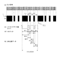
- the CLK signal shown in FIG. 15A is output from the clock generation unit 3 shown in FIG. 14 to the counter unit 40.
- the bar code symbol 1 shown in FIG. 15B is, for example, that of the CODE128 standard.
- the full width of one character is composed of 11 modules.
- the black bar (1) of the character C1 is composed of 4 modules, and the bars (3) and (5) are each composed of 1 module.
- the white space (2) consists of one module, and the spaces (4) and (6) each consist of two modules.
- the barcode data value D30 shown in FIG. 15C is obtained by sampling the code reading data D2 output from the optical reading unit 2 shown in FIG. 14 based on the CLK signal output from the clock generation unit 3, The code read data D2 is counted based on the CLK signal, and the code read data D2 is obtained by converting the code read data D2 into count data D4 indicating the width of an element including a white space and a black bar.
- W11 shown in FIG. 15D is the width of the bar (1) of the black portion of the character C1.
- W12 is the width of the space (2) following the bar (1).
- W13 is the width of the bar (3) following the space (2) of the character C1.
- W14 is the width of the space (4) following the bar (3) of the character C1.
- W15 is the width of the bar (5) following the space (4).
- W16 is the width of the space (6) following the bar (5) of the character C1.
- W21 shown in (E) of FIG. 15 is a width obtained by adding the bar (1) and the space (2) of the character C1 by the CPU 33 (hereinafter referred to as bar (1) + space (2)).
- the counted data value indicating the added width of the bar (1) + the space (2) forms the width W21 data.
- W22 is a width obtained by adding the space (2) and the bar (3) following the bar (1) of the character C1 by the CPU 33.
- the counted data value indicating the added width of the space (2) + the bar (3) forms the width W22 data.
- W23 is a width obtained by adding the bar (3) and the space (4) following the space (2) of the character C1 by the CPU 33.
- the counted data value indicating the added width of the bar (3) + the space (4) forms the width W23 data.
- W24 is a width obtained by adding the space (4) and the bar (5) following the bar (3) of the character C1 by the CPU 33.
- the counted data value indicating the added width of the space (4) + the bar (5) forms the width W24 data.
- W25 is a width obtained by adding the bar (5) and the space (6) following the space (4) of the character C1 by the CPU 33.
- the counted data value indicating the added width of the bar (5) + the space (6) forms the width W25 data.
- the above-described five types of width W21 data to width W25 data are two-addition data for one character, and constitute a barcode data value D30.
- FIGS. 16 and 17 are flowcharts showing decoding examples (parts 1 and 2) of the obfuscated character according to the conventional example.
- the optical information reader 20 reads the bar code symbol 1 based on the CODE128 standard, searches for the start margin, decodes the character following the start margin by the two-addition method, and outputs the bar code data D12. Take the case as an example.
- the error tolerance (maximum error range) of each element of the bar and space of the bar code symbol 1 is set to ⁇ 0.5 module, for example.
- the CPU 33 searches for a start margin in step ST81 of the flowchart shown in FIG.
- the optical reading unit 2 reads the bar code symbol 1 and generates code reading data D2.
- the code reading data D2 is output from the optical reading unit 2 to the counter unit 40.
- the clock generation unit 3 outputs a sampling signal CLK signal having a predetermined frequency to the counter unit 40.
- the counter unit 40 receives the code reading data D2 output from the optical reading unit 2, and also receives the CLK signal output from the clock generation unit 3, counts the code reading data D2 based on the CLK signal, and reads the code.
- the data D2 is converted into count data D4 indicating the addition width of two elements including a white space and a black bar.
- the count data D4 is a numerical data string indicating the width of each bar (black part) and the width of a space (white part) in the barcode symbol 1.
- the count data D4 is stored in the count data value storage unit 30.
- the m-stage data buffer 5 temporarily stores the count data D4 output from the counter unit 40 for m stages (m is an arbitrary integer).
- the m stage is arbitrarily set depending on the printing state of the bar code symbol 1.
- the x multiplier 7 is preset with “x” indicating how many times the count data D4 is multiplied, performs an x-times operation, and outputs x-times data D7. .
- the selector unit 6 receives the selection control of the CPU 33 and selects data to be compared among the m-stage count data D4 temporarily stored in the m-stage data buffer 5.
- the comparator 8 compares each count data D4 selected by the selector unit 6 up to k stages in the m-stage data buffer 5 with the x-times data D7 output from the x multiplier 7.
- SMF data D9 When the x-fold data D7 from the x multiplier 7 is smaller as a result of the comparison, it is determined that there is a start margin candidate, and a start margin candidate search flag (hereinafter referred to as SMF data D9) is generated.
- SMF data D9 is output to the start margin storage unit 9.
- step ST82 the CPU 33 extracts width data (6 pieces) for one character.
- the width W11 of the black portion bar (1) is counted by the counter unit 40, and the counted data value becomes the width W11 data.
- the width W12 of the white space (2) following the bar (1) is also counted by the counter unit 40, and the counted data value becomes the width W12 data.
- the width W13 of the bar (3) following the space (2) is counted by the counter unit 40, and the counted data value becomes the width W13 data.
- the width W14 of the space (4) following this bar (3) is also counted by the counter unit 40, and the counted data value becomes the width W14 data.
- the counter unit 40 counts the width W15 of the bar (5) following the space (4), and the counted data value becomes the width W15 data.
- the counter unit 40 also counts the width W16 of the space (6) following the bar (5), and the counted data value becomes the width W16 data.
- the above-described six types of width W11 data to width W16 data constitute the barcode data value D30.
- the barcode data value D30 is output to the CPU 23 via the interface unit 11.
- step ST83 the CPU 33 calculates the one module width of the character C1.
- the CPU 33 obtains the number of modules of the two-addition pattern by converting the barcode data value D30 of six widths W11 to W16 data for one character into the number of character modules.
- the barcode data value D30 of six widths W11 to W16 data for one character into the number of character modules.
- width W21 data to width W25 data are sequentially output to the CPU 33 from the count data value of the counter unit 40.
- the CPU 33 inputs the width W21 data and obtains the number of modules of the added width W21 obtained by adding the bar (1) and the space (2) of the character C1.
- the number of modules of the addition width W21 is rounded to the nearest integer so that the maximum error of each element such as a bar or space is within 0.5. For example, when the number of modules of W21 is 2.4, the number of modules of W21 is “2”. When the number of modules is 2.6, the number of modules of W21 is “3”.
- step ST84 the CPU 33 converts the barcode data value D30 for one character into a two-piece addition pattern.
- the counted data value indicating the added width W21 obtained by adding the bar (1) and the space (2) of the character C1 shown in (E) of FIG. 15 by the CPU 33 is the width W21 data.
- the counted data value indicating the added width W22 obtained by adding the space (2) and the bar (3) following the bar (1) of the character C1 by the CPU 33 is the width W22 data.
- the counted data value indicating the added width W23 obtained by adding the bar (3) and the space (4) following the space (2) of the character C1 by the CPU 33 is the width W23 data.
- the counted data value indicating the added width W24 obtained by adding the space (4) and the bar (5) following the bar (3) of the character C1 by the CPU 33 is the width W24 data.
- the counted data value indicating the added width W25 obtained by adding the bar (5) and the space (6) following the space (4) of the character C1 by the CPU 33 is the width W25 data.
- step ST85 the CPU 33 searches for a character that matches the previously converted two addition pattern.
- the CPU 33 previously converts the five types of the width W21 data to the width W25 data (two-piece addition data). A character whose module value matches the theoretical value of the expected value character is searched. In the conventional method, the character is determined at this stage.
- step ST86 the CPU 33 branches the control based on the presence or absence of a matching character. If there is a matching character, in step ST87, the character whose two addition patterns match is taken as the decoding result. Thereafter, the process proceeds to step ST88 shown in FIG.
- step ST88 the CPU 33 branches the control based on whether or not the character is immediately after the margin. If the decoded character is not a character immediately after the margin, the process proceeds to step ST89, and the CPU 33 branches the control based on whether the decoded result is a stop character.
- step ST90 the CPU 33 executes error detection (parity check) and branches the control based on whether or not the check digit is correct. If the check digit is correct, the CPU 33 completes reading in step ST91, outputs the barcode data D12 of the decode buffer 25, and clears the decode buffer 25 (normal end). Thereafter, the process proceeds to step ST95.
- error detection parity check
- step ST92 the CPU 33 branches the control based on whether or not the decoding result is a start character.
- step ST83 the CPU 33 executes a decoding process of the next character (six bar code data values D30). Thereafter, the process returns to step ST81.
- step ST86 if there is no matching character in step ST86 shown in FIG. 16, if the decoding result is not a start character in step ST92 shown in FIG. 17, or if the check digit is incorrect in step ST90, step ST94. Then, the CPU 33 executes read error processing. In the reading error process, the next margin is searched.
- step ST95 the CPU 33 determines the end. For example, when a reading end command is detected for the optical information reading device 20 and a reading end command is detected, the reading control of the bar code symbol 1 is ended. If the reading end command is not detected, the process returns to step ST81 to repeat the above-described contents in order to continue reading control of the bar code symbol 1.
- the optical information reading device 20 it is possible to decode the hard-to-read character by introducing the double width addition method for one character into the configuration of the bar code symbol reading device as shown in Patent Document 1.
- the conventional optical information reader 20 when calculating a character pattern, the error tolerance of each element including a bar and a space is set within ⁇ 0.5 modules, and six width W11 data to width W16 for one character.
- the barcode data value D30 of the data is converted into the number of modules of the character, and the number of modules of the two addition pattern is obtained.
- the number of modules in the two-addition pattern is rounded to the nearest integer so that the maximum error of each element such as a bar or space is within 0.5.
- the count value of the number of modules of the character having the added width W21 is 2.4, the number of modules is rounded off to the nearest integer even though it is originally “2” and “3” as integer candidates.
- the number of modules is set to “2” (see step ST83).
- the optical information reading device adds 2 (n to n) widths of n (n ⁇ 2) elements including adjacent bars and spaces in one character to 2 to n.
- Each of the addition element widths is obtained, and each of the 2 to n addition element widths is converted into the number of modules of one character to obtain the number of modules of the 2 to n addition element widths.
- Extraction means for extracting candidate characters by narrowing down the target characters in which the number of modules of each of the 2 to n added element widths is an integer within an error of 1, and each of the 2 to n extracted by the extraction means
- the candidate character of the number of modules of this addition element width is compared with the expected value character for evaluating the candidate character, and the candidate character Also characterized in that comprises a search means for searching a strong expectation character correlation.
- the calculation means when the barcode symbol is read and the decoding result is output, the calculation means includes n (n ⁇ 2) lines including adjacent bars and spaces in one character. 2 to n element widths are obtained by adding the widths of the elements, and each of the 2 to n element widths is converted into the number of modules of one character, and the number of modules having the element width of 2 to n elements is calculated. Ask for.
- the extraction means extracts, as candidate characters, characters whose number of modules of 2 to n addition element widths obtained by the calculation means is an integer within an error of 1. Based on these assumptions, the search means compares each 2 to n candidate element width candidate characters extracted by the extraction means with an expected value character for evaluating the candidate character, and An expected value character having the strongest correlation with the character is searched.
- the barcode data of the expected value character having the strongest correlation with the candidate character extracted from the plurality of candidate characters can be output as the decoding result at the time of reading the barcode symbol. Compared to the reading method, it is possible to prevent erroneous barcode reading.
- the optical information reader according to claim 2 is the optical information reader according to claim 1, wherein when the calculation means obtains the 2 to n additional element widths of the target character, the character bars before and after the target character and A feature is that the widths of elements including spaces are added.
- the optical information reading device is the optical information reading device according to claim 1, wherein the extracting unit obtains n width data for one character when each of the 2 to n additional element widths of the target character is obtained. And one or more width data before and after the target character.
- An optical information reader is the optical information reading device according to the first aspect, wherein the search means has two types for the 2 to n addition element widths of the plurality of target characters obtained from the extraction means. A target character that matches any of the target characters is searched, and the number of candidate characters is narrowed down.
- the optical information reader according to claim 5 is the optical information reader according to claim 1, wherein the search means calculates an error between an actual value of the number of modules of the candidate character and an ideal value of the number of modules of the expected value character. Then, an expected value character having the strongest correlation with the candidate character having the smallest error value obtained by summing up the errors is searched for.
- the optical information reader according to claim 6 is characterized in that, in claim 5, the search means detects the expected value character that matches the candidate character having the smallest error value. .
- the optical information reading device is the optical information reading device according to claim 1, wherein a total value obtained by adding widths of n (n ⁇ 2) elements including adjacent bars and spaces in the one character, and the one character And a comparison means for comparing whether or not the width data for one character is appropriate based on the comparison result.
- optical information reading method wherein the optical information reading device adds 2 to n addition elements by adding the widths of n (n ⁇ 2) elements including adjacent bars and spaces in one character. Obtaining each of the widths, converting each of the obtained 2 to n addition element widths into the number of modules of one character to obtain the number of modules of the 2 to n addition element widths, and obtaining the obtained 2 to a step of extracting candidate characters by narrowing down target characters in which the number of modules of each of the n added element widths is an integer within an error of 1, and a candidate character having the number of modules of each of the extracted 2 to n added element widths And the expected value character for evaluating the candidate character, and the expected value character having the strongest correlation with the candidate character is detected. It is characterized in that to perform the steps of.
- An optical information reading method is the optical information reading method according to the eighth aspect, wherein when the 2 to n additional element widths of the target character are obtained, the bars and spaces of the characters before and after the target character are calculated. The width is added.
- An optical information reading method is the optical information reading method according to the ninth aspect, wherein the width data for the one character and the one before and after the character are calculated when the 2 to n additional element widths are obtained. The above width data is extracted.
- An optical information reading method is the optical information reading method according to the tenth aspect, which matches any one of the two types of the target character with respect to the 2 to n addition element widths of the plurality of extracted target characters.
- the target character is searched and the number of candidate characters is narrowed down.
- An optical information reading method is the optical information reading method according to the eighth aspect, wherein an error between an actually measured value of the number of modules of the candidate character and an ideal value of the number of modules of the expected value character is calculated. An expected value character having the strongest correlation with the candidate character having the smallest error value obtained by summing is extracted.
- An optical information reading method is characterized in that, in the twelfth aspect, the expected value character matching the candidate character having the smallest error value is detected.
- the optical information reading method according to claim 14 is the optical information reading method according to claim 8, wherein a total value obtained by adding widths of n (n ⁇ 2) elements including adjacent bars and spaces in the one character and the one character Are compared with the full width value indicating the full width of the character, and based on the comparison result, it is determined whether or not the width data for the one character is appropriate.
- the computer-readable program according to claim 15 is characterized by combining instructions for executing the optical information reading method according to claims 8 to 14.
- the computer-readable recording medium according to claim 16 is characterized in that a program for executing the optical information reading method according to claims 8 to 14 is described.
- candidates are obtained by narrowing down target characters in which the number of modules of each of 2 to n addition element widths is an integer within an error of 1. Characters are extracted, and each of the extracted 2 to n candidate element width candidate characters is compared with the expected value character for evaluating the candidate character, and the most correlated with the candidate character. Search means for searching for a strong expected value character is provided.
- barcode data of an expected value character having the strongest correlation with candidate characters extracted from a plurality of candidate characters can be output as a decoding result at the time of reading the barcode symbol. Compared to the reading method, it is possible to prevent erroneous barcode reading.
- the optical information reading device when each of the 2 to n additional element widths of the target character is obtained, Since the width of the element including the bar and space is added, the barcode data of the expected value character having the strongest correlation with the candidate character extracted from the plurality of candidate characters can be output as the decoding result when the barcode symbol is read. become.
- n for the one character is obtained. Since the width data of the book and one or more width data before and after the target character are extracted, the barcode data of the expected value character having the strongest correlation with the candidate character extracted from the plurality of candidate characters is displayed. It becomes possible to output as a decoding result at the time of reading a symbol.
- n width data for one character and one or more width data before and after the character are extracted.
- more candidate characters can be extracted in which the number of modules of each of the 2 to n addition element widths is an integer within an error of 1 compared to the conventional method, and the first strongest correlation is decoded.
- two types of the extracted 2 to n additional element widths of each of the plurality of target characters extracted are used. Since the target character that matches any of the target characters is searched and the number of candidate characters is narrowed down, it is possible to greatly prevent the erroneous reading of the barcode as compared with the conventional barcode reading method.
- the candidate character having the smallest error value and the expected value character having the strongest correlation are searched. Compared to the barcode reading method, it is possible to prevent erroneous barcode reading.
- an expected value character that matches a candidate character having a minimum error value is detected. Compared to the reading method, it is possible to prevent erroneous barcode reading.
- the command for executing the optical information reading method according to the present invention since the command for executing the optical information reading method according to the present invention is combined, it is extracted from a plurality of candidate characters.
- the barcode data of the expected value character having the strongest correlation with the candidate character can be output as the decoding result when the barcode symbol is read. Therefore, bar code reading errors can be greatly prevented as compared with the conventional bar code reading method.
- FIG. 1 It is a block diagram which shows the structural example of the barcode symbol reader 100 as embodiment which concerns on this invention.
- (A) to (G) are explanatory diagrams showing calculation examples of single data and 2 to 6 addition data according to the first embodiment.
- FIG. 1 shows the example of decoding of an obfuscated character (the 2).
- (A) to (G) are explanatory diagrams showing another calculation example (part 1) of the single data and the two to six addition data according to the first embodiment.
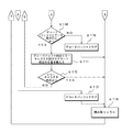
- (A) to (G) are explanatory diagrams showing another calculation example (part 2) of the single data and the two to six addition data according to the first embodiment. It is explanatory drawing which shows the barcode symbol example of CODE128, its missing example, and its reconstruction example. It is explanatory drawing which shows the barcode symbol example of CODE128, its missing example, and its reconstruction example. It is explanatory drawing which shows the barcode symbol example of CODE128, its missing example, and its reconstruction example. It is explanatory drawing which shows the barcode symbol example of CODE128, its missing example, and its reconstruction example. It is a flowchart which shows the decoding example (the 1) of the obfuscated character which concerns on a 2nd Example. It is a flowchart which shows the example of decoding of an obfuscated character (the 2).
- the present invention makes it possible to prevent erroneous barcode reading as compared with the conventional barcode reading method, and to output accurate barcode data even when the element is scratched or faint.
- An object is to provide an optical information reading apparatus, an optical information reading method, a computer readable program, and a recording medium.
- a bar code symbol reading device 100 shown in FIG. 1 constitutes an example of an optical information reading device, reads a bar code symbol 1, searches for its start margin, and further decodes characters following the start margin to decode the bar code. Data D12 is output.
- the bar code symbol reading apparatus 100 includes an optical reading unit 2, a clock generation unit 3, a counter unit 4, an m-stage data buffer 5, an x multiplier 7, a selector unit 6, a comparator 8, a start margin storage unit 9, and width data storage.
- Unit 10 interface unit 11, microprocessor 12, and decode buffer 25.
- the description is abbreviate
- the counter unit 4 receives the code reading data D2 output from the optical reading unit 2, and also receives the CLK signal output from the clock generation unit 3, counts the code reading data D2 based on the CLK signal,
- the read data D2 is converted into count data D4 (barcode data value: numerical value) indicating one width of an element including a white space and a black bar, or n added width.
- the width data storage unit 10 is connected to the counter unit 4.
- the width data storage unit 10 stores and stores all the count data D4 related to the target character of 1 width and n added widths sequentially output from the counter unit 4 in time series.
- the width data storage unit 10 includes a flip-flop circuit, a storage circuit such as a DRAM, and the like.
- the width data storage unit 10 outputs the count data D4 related to the target character having one width and n additional widths as width data D10 (corresponding to the barcode data value D30) of each character.
- An interface unit 11 is connected to the start margin storage unit 9 and the width data storage unit 10.
- the microprocessor 12 executes barcode recognition processing using the SMF data D9 input via the interface unit 11 and the width data D10 of each character.
- the microprocessor 12 includes a read-only memory (Read Memory: hereinafter referred to as ROM21) for storing programs, a memory (Random Access Memory: hereinafter referred to as RAM22) in which work information can be written and read as needed, and a central processing unit (Central).
- the microcomputer includes a processing unit (hereinafter referred to as a CPU 23) and an expected value storage unit 24.
- the ROM 21 constitutes an example of a recording medium.
- the ROM 21 stores a program data Dp that is a computer-readable program and is combined with a command for executing the optical information reading method according to the present invention.
- the content of the bar code symbol reading apparatus 100 includes the step of adding the widths of n (n ⁇ 2) elements including adjacent bars and spaces in one character to obtain 2 to n added element widths, respectively.
- Each of the obtained 2 to n addition element widths is converted into the number of modules of one character to obtain the number of modules of the 2 to n addition element widths, and the obtained 2 to n addition element widths are calculated.
- the candidate character is a character that narrows down the target character.
- the program data Dp includes system program data for starting the system.
- the RAM 22 temporarily stores control information for executing calculations for executing the optical information reading method, and controls such as extraction, search, and comparison. Is done. For example, when the power is turned on, the CPU 23 that has detected the power-on information reads the system program from the ROM 21, develops it in the RAM 22, activates the system, and controls the entire barcode symbol reader 100.
- the CPU 23 has at least four functions such as a calculation unit 23a, an extraction unit 23b, a comparison unit 23c, and a search unit 23d.
- the calculation unit 23a constitutes an example of a calculation means, and inputs the width data D10 of each target character. Based on the width data D10, the calculation unit 23a includes n (n ⁇ 2) elements including adjacent bars and spaces in one character. The width is added to obtain 2 to n additional element widths. The calculation unit 23a converts each of the obtained 2 to n addition element widths into the number of modules of one character and obtains the number of modules of the 2 to n addition element widths.
- the extraction unit 23b narrows down the target characters in which the number of modules of each of the 2 to n addition element widths (hereinafter also referred to as 2 to n addition patterns) obtained by the calculation unit 23a is an integer with an error of 1 or less. Extract characters. When each of the 2 to n addition patterns is obtained, the extraction unit 23b extracts n width data D10 for one character and one or more width data D10 before and after the target character.
- the target character extraction standard is expanded from an integer with an error of 0.5 or less in the conventional method to an integer with an error of 1 or less, n width data D10 for one character, and before and after the target character.
- One or more width data D10 are extracted. Accordingly, it is possible to extract more target characters in which the number of modules of each of the 2 to n addition element widths is an integer within an error of 1 as compared with the conventional method.
- not only the first strongest correlation is used as the decoding result, but also the decoding result candidates such that the second, third,... Multiple characters can be output. As a result, it is possible to largely prevent erroneous barcode reading as compared with the conventional barcode reading method.
- the comparing unit 23c compares each candidate character having the number of modules of 2 to n added element widths extracted by the extracting unit 23b with an expected value character (theoretical value) for evaluating the candidate character.
- the comparison unit 23c has a discrimination function, and includes a total value obtained by adding the widths of n (n ⁇ 2) elements including adjacent bars and spaces in one character, and a full width value indicating the full width of one character. Are compared, and based on the comparison result, it is determined whether or not the width data D10 for one character is appropriate.
- This determination makes it possible to determine the disappearance or division of character bars.
- the target character can be narrowed down based on the determination result such as disappearance or division of the bar, the calculation amount can be reduced, and the processing time can be increased.
- the search unit 23d searches for an expected value character having the strongest correlation with the candidate character. For example, when the above-described calculation unit 23a calculates an error between the measured value of the number of modules of the candidate character and the ideal value of the number of modules of the expected value character, the search unit 23d calculates the error calculated by the calculation unit 23a. An expected value character having the strongest correlation with the candidate character having the smallest error value obtained by summing is searched. In this example, since the expected value character having the strongest correlation with the candidate character having the smallest error value is searched, it is possible to largely prevent the erroneous reading of the barcode as compared with the conventional barcode reading method.
- the expected value storage unit 24 is connected to the microprocessor 12.
- the expected value storage unit 24 stores expected value characters (theoretical values).
- the expected value character is the number of modules (theoretical value) constituting each element of the CODE128 standard character.
- the calculation unit 23a, the extraction unit 23b, the comparison unit 23c, and the search unit 23d in the CPU 23 may be configured by either software or hardware.
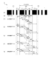
- FIGS. 2A to 2G a calculation example of the single data and the two to six additional data according to the first embodiment will be described.
- the barcode symbol 1 of the CODE128 standard will be described.
- one character shown in FIG. 2A has three black bars (1), (3), (5) and three white spaces (2), (4 ), (6).
- C1 is the target character
- C0 is the character immediately before the target character
- C2 is the character immediately behind it.
- the full width of one character is composed of 11 modules.
- the black bar (1) consists of 4 modules, and the bars (3) and (5) each consist of 1 module.
- the white space (2) consists of 4 modules, and the spaces (4) and (6) each consist of 2 modules.
- start codes there are 3 types of start codes, each representing 103 types of code patterns.
- ASCII 128 characters can be expressed. If the start code C is used, two digits can be expressed with one character, which can be expressed with a very high printing density.
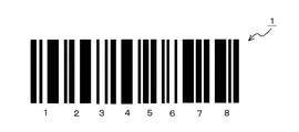
- the barcode symbol 1 of CODE128 is composed of 8 characters (see FIG. 5A). The sum of the number of modules used for the bar is even parity, and the sum of the number of modules used for the space is odd parity. It has a self-function that uses even parity and odd parity.
- W11 shown in FIG. 2B is the width of the black bar (1) of the target character C1.
- the width of the bar (1) is counted by the counter unit 4, and the counted data value forms the width W11 data.
- W12 is the width of the space (2) following the bar (1).
- the width of the space (2) is also counted by the counter unit 4, and the counted data value forms the width W12 data.
- W13 is the width of the bar (3) following the space (2) of the target character C1.
- the width of the bar (3) is counted by the counter unit 4, and the counted data value forms the width W13 data.
- W14 is the width of the space (4) following the bar (3) of the target character C1.
- the width of the space (4) is also counted by the counter unit 4, and the counted data value forms the width W14 data.
- W15 is the width of the bar (5) following the space (4).
- the width of the bar (5) is counted by the counter unit 4, and the counted data value forms the width W15 data.
- W16 is the width of the space (6) following the bar (5) of the target character C1.
- the width of the space (6) is also counted by the counter unit 4, and the counted data value forms the width W16 data.
- the above-mentioned six kinds of width W11 data to width W16 data are one data of one character, and constitute the width data D10.
- W21 shown in FIG. 2C is a width (hereinafter referred to as bar (1) + space (2)) obtained by adding the bar (1) and the space (2) of the target character C1 by the calculation unit 23a. .
- the counted data value indicating the added width of the bar (1) + the space (2) forms the width W21 data.
- W22 is a width obtained by adding the space (2) and the bar (3) following the bar (1) of the target character C1 by the calculation unit 23a.
- the counted data value indicating the added width of the space (2) + the bar (3) forms the width W22 data.
- W23 is a width obtained by adding each of the bar (3) and the space (4) following the space (2) of the target character C1 by the calculation unit 23a.
- the counted data value indicating the added width of the bar (3) + the space (4) forms the width W23 data.
- W24 is a width obtained by adding the space (4) and the bar (5) following the bar (3) of the target character C1 by the calculation unit 23a.
- the counted data value indicating the added width of the space (4) + the bar (5) forms the width W24 data.
- W25 is a width obtained by adding the bar (5) and the space (6) following the space (4) of the target character C1 by the calculation unit 23a.
- the counted data value indicating the added width of the bar (5) + the space (6) forms the width W25 data.
- the above-mentioned five kinds of width W21 data to width W25 data are two-element added data for one character, and form width data D10.
- W32 is a width obtained by adding the space (2), the bar (3), and the space (4) following the bar (1) of the target character C1 by the calculation unit 23a.
- the counted data value indicating the added width of the space (2) + the bar (3) + the space (4) forms the width W32 data.
- W33 is a width obtained by adding the bar (3), the space (4), and the bar (5) following the space (2) of the target character C1 by the calculation unit 23a.
- the counted data value indicating the added width of the bar (3) + the space (4) + the bar (5) forms the width W33 data.
- W34 is a width obtained by adding the space (4), the bar (5), and the space (6) following the bar (3) of the target character C1 by the calculation unit 23a.
- the counted data value indicating the added width of space (4) + bar (5) + space (6) forms width W34 data.
- the above-described four types of the width W31 data to the width W34 data are added data of 3 characters for one character, and form the width data D10.
- 2E is a width obtained by adding the bar (1), the space (2), the bar (3), and the space (4) of the target character C1 by the calculation unit 23a.
- the counted data value indicating the added width of the bar (1) + the space (2) + the bar (3) + the space (4) forms the width W41 data.
- the target character C1 of W42 has a width obtained by adding the space (2), the bar (3), the space (4), and the bar (5) following the bar (1) by the calculation unit 23a.
- the counted data value indicating the added width of the space (2) + bar (3) + space (4) + bar (5) forms the width W42 data.
- W43 is a width obtained by adding the bar (3), the space (4), the bar (5), and the space (6) following the space (2) of the target character C1 by the calculation unit 23a.
- the counted data value indicating the added width of the bar (3) + the space (4) + the bar (5) + the space (6) forms the width W43 data.
- the above-mentioned three types of width W41 data to width W43 data are four addition data of one character, and form width data D10.
- W51 shown in FIG. 2F is a width obtained by adding the bar (1), the space (2), the bar (3), the space (4), and the bar (5) of the target character C1 by the calculation unit 23a. is there.
- the counted data value indicating the added width of the bar (1) + the space (2) + the bar (3) + the space (4) + the bar (5) forms the width W51 data.
- W52 is the width obtained by adding the space (2), bar (3), space (4), bar (5), and space (6) following the bar (1) of the target character C1 by the calculation unit 23a.
- the counted data value indicating the added width of space (2) + bar (3) + space (4) + bar (5) + space (6) forms width W52 data.
- the above-described two types of width W51 data and width W52 data are 5-character addition data for one character, and form width data D10.
- W61 shown in (G) of FIG. 2 indicates that each of the bar (1), the space (2), the bar (3), the space (4), the bar (5), and the space (6) of the target character C1 is calculated by the calculation unit 23a.
- the added width The counted data value indicating the added width of the bar (1) + the space (2) + the bar (3) + the space (4) + the bar (5) + the space (6) forms the width W61 data.
- One type of width W61 data is 6-character addition data for one character, and forms width data D10.
- width W11 data to width W16 data (one data), five kinds of width W21 data to width W25 data (two addition data), four kinds of data Width W31 data to width W34 data (three-piece addition data), three kinds of width W41 data to width W43 data (four-piece addition data), two kinds of width W51 data and width W52 data (5-piece addition data), and 1 Twenty-one types of target characters are obtained in total of the types of width W61 data (six added data).
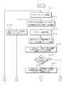
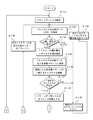
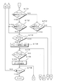
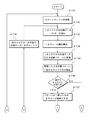
- an optical information reading method will be described with reference to FIGS. 3 and 4 and an example of decoding an obfuscated character according to the first embodiment.
- the barcode symbol 1 based on the CODE128 standard is read to search for the start margin, and the target character following the start margin is further decoded to output the barcode data D12.
- the error tolerance (maximum error range) of each element of the bar and space of the bar code symbol 1 is set to ⁇ 1.0 module.
- the barcode character 1 will be described with respect to the target character C1 shown in FIG. 2 (character decoding algorithm).
- the microprocessor 12 searches for a start margin in step ST1 of the flowchart shown in FIG.
- the optical reading unit 2 reads the bar code symbol 1 and generates code reading data D2.
- the code reading data D2 is output from the optical reading unit 2 to the counter unit 4.
- the clock generator 3 outputs a sampling signal CLK signal having a predetermined frequency to the counter unit 4.
- the counter unit 4 receives the code reading data D2 output from the optical reading unit 2, and also receives the CLK signal output from the clock generation unit 3, counts the code reading data D2 based on the CLK signal, and reads the code.
- Data D2 is converted into count data D4 indicating the width of one element and the added width of six elements including a white space and a black bar.
- the count data D4 is a numerical data string indicating the width of each bar (black part) and the width of a space (white part) in the barcode symbol 1.
- the count data D4 is stored in the width data storage unit 10.
- the m-stage data buffer 5 temporarily stores the count data D4 output from the counter unit 4 for m stages (m is an arbitrary integer).
- the m stage is arbitrarily set depending on the printing state of the bar code symbol 1.
- the x multiplier 7 is preset with “x” indicating how many times the count data D4 is multiplied, performs an x-times operation, and outputs x-times data D7. .
- the selector unit 6 receives selection control of the microprocessor 12 and selects data to be compared among the count data D4 for m stages temporarily stored in the m-stage data buffer 5.
- the comparator 8 compares each count data D4 selected by the selector unit 6 up to k stages in the m-stage data buffer 5 with the x-times data D7 output from the x multiplier 7.
- SMF data D9 When the x-fold data D7 from the x multiplier 7 is smaller as a result of the comparison, it is determined that there is a start margin candidate, and a start margin candidate search flag (hereinafter referred to as SMF data D9) is generated.
- SMF data D9 is output to the start margin storage unit 9.
- step ST2 the CPU 23 extracts the width data D10 (6 pieces) for one character and the width data D10 for every 5 pieces before and after that.
- the width W11 of the black bar (1) is counted by the counter unit 4, and the counted data value becomes the width W11 data.
- the width W12 of the white space (2) following the bar (1) is also counted by the counter unit 4, and the counted data value becomes the width W12 data.
- the width W13 of the bar (3) following the space (2) is counted by the counter unit 4, and the counted data value becomes the width W13 data.
- the width W14 of the space (4) following this bar (3) is also counted by the counter unit 4, and the counted data value becomes the width W14 data.
- the width W15 of the bar (5) following the space (4) is counted by the counter unit 4, and the counted data value becomes the width W15 data.
- the width W16 of the space (6) following the bar (5) is also counted by the counter unit 4, and the counted data value becomes the width W16 data.
- the above-described six types of the width W11 data to the width W16 data constitute the width data D10.
- the width data D10 is output to the CPU 23 via the interface unit 11.
- each of the bar (1) and the space (2) of the target character C1 shown in (C) of FIG. 2 is added by the calculation unit 23a, and the counted data value indicating the added width W21 becomes the width W21 data.
- Each of the space (2) and the bar (3) following the bar (1) of the target character C1 is added by the calculation unit 23a, and the counted data value indicating the added width W22 becomes the width W22 data.
- Each of the bar (3) and the space (4) following the space (2) of the target character C1 is added by the calculation unit 23a, and the counted data value indicating the added width W23 becomes the width W23 data.
- Each of the space (4) and the bar (5) following the bar (3) of the target character C1 is added by the arithmetic unit 23a, and the counted data value indicating the added width W24 becomes the width W24 data.
- Each of the bar (5) and the space (6) following the space (4) of the target character C1 is added by the arithmetic unit 23a, and the counted data value indicating the added width W25 becomes the width W25 data.
- the above-mentioned five types of the width W21 data to the width W25 data constitute the width data D10.
- Each of the bar (1), the space (2), and the bar (3) of the target character C1 shown in (D) of FIG. 2 is added by the arithmetic unit 23a, and the counted data value indicating the added width W31 is the width W31 data. It becomes.
- Each of the space (2), the bar (3), and the space (4) following the bar (1) of the target character C1 is added by the computing unit 23a, and the counted data value indicating the added width W32 becomes the width W32 data.
- Each of the bar (3), the space (4), and the bar (5) following the space (2) of the target character C1 is added by the calculation unit 23a, and the counted data value indicating the added width W33 becomes the width W33 data.
- Each of the space (4), the bar (5), and the space (6) following the bar (3) of the target character C1 is added by the computing unit 23a, and the counted data value indicating the added width W34 becomes the width W34 data.
- the above-described four types of the width W31 data to the width W34 data constitute the width data D10.
- Each of the bar (1), space (2), bar (3), and space (4) of the target character C1 shown in (E) of FIG. 2 is added by the calculation unit 23a, and count data indicating the added width W41.
- the value is the width W41 data.
- each of the space (2), the bar (3), the space (4), and the bar (5) following the bar (1) is added by the calculation unit 23a, and the counted data value indicating the added width W42 is a width. W42 data.
- width W43 data Each of the bar (3), the space (4), the bar (5), and the space (6) following the space (2) of the target character C1 is added by the arithmetic unit 23a, and the counted data value indicating the added width W43 is a width. W43 data.
- the above three types of width W41 data to width W43 data constitute the width data D10.
- the count data value indicating W51 is the width W51 data.
- Each of the space (2), bar (3), space (4), bar (5), and space (6) following the bar (1) of the target character C1 is added by the calculation unit 23a to indicate the added width W52.
- the count data value forms the width W52 data.
- the two types of width W51 data and width W52 data described above constitute the width data D10.
- width W61 data One type of width W61 data constitutes width data D10.
- width W11 data to width W16 data (one data), five kinds of width W21 data to width W25 data (two addition data), four kinds of data Width W31 data to width W34 data (three-piece addition data), three kinds of width W41 data to width W43 data (four-piece addition data), two kinds of width W51 data and width W52 data (5-piece addition data), and 1 Twenty-one types of target characters are obtained in total of the types of width W61 data (six added data).
- step ST3 the CPU 23 calculates one module width of the target character C1.
- the calculation unit 23a converts each of the previously obtained 2 to 6 addition patterns (element width) into the number of modules of one character and obtains the number of modules of the 2 to 6 addition patterns.
- six types of width W11 data to width W16 data and five types of width W21 data to width are calculated from the count data value output from the counter unit 4.
- W25 data, four types of width W31 data to width W34 data, three types of width W41 data to width W43 data, two types of width W51 data and width W52 data, and one type of width W61 data are sequentially output to the CPU 23. .
- the tolerance can be increased until the error tolerance of each element is within 1.0. Since the allowable amount is increased, it is possible to increase the conditions for taking the target character match. As a result, it is possible to prevent erroneous reading of the bar code symbol 1.
- step ST4 the CPU 23 converts the extracted 21 types of width data D10 into 1-6 addition patterns (element widths).
- six types of width W11 data to width W16 data are converted into single data of one character, and a single pattern is created as a recognized pattern of the target character C1 based on the single data.
- Five types of width W21 data to width W25 data are converted into double addition data of one character, and a double addition pattern (recognized pattern) of the target character C1 based on the double addition data is created.
- the four types of the width W31 data to the width W34 data are converted into the three added data of one character, and the three added knowledge pattern of the target character C1 based on the three added data is created.
- width W41 data to width W43 data are converted into 4-character addition data of one character, and a 4-addition pattern of the target character C1 based on the 4-addition data is created.
- the two types of width W51 data and width W52 data are converted into 5-character addition data for one character, and a 5-addition pattern for the target character C1 based on the 5-addition data is created.
- One type of width W61 data is converted into six character addition data of one character, and a six character addition pattern of the target character C1 based on the six character addition data is created.
- step ST5 in order to narrow down the target characters, the CPU 23 searches for target characters having an error of the number of modules within 1 for all of the 1 pattern and 2-6 addition patterns, and determines candidate characters.
- the extraction unit 23b extracts candidate characters by narrowing down target characters in which the number of modules of each of the one pattern and the two to six addition patterns obtained by the calculation unit 23a is an integer within an error of 1. .
- the extraction unit 23b obtains the six width data D10 for one character of the one pattern and the two to six addition patterns obtained by the calculation unit 23a, and (6-1) data before and after the target character. Width data D10 is extracted.
- step ST6 the CPU 23 branches the control based on whether one or more candidate characters exist. If there are one or more target characters (plural), the error between the actual value of the 1-6 addition pattern and its ideal value is calculated in step ST7, and the candidate character whose sum of errors is minimized Is the decoding result.
- the candidate character having the smallest error value is the character having the strongest correlation with the expected value character. In this example, the target character with the smallest overall error can be selected as a candidate character.
- the CPU 23 reads the expected value character (theoretical value) from the expected value storage unit 24 to the comparison unit 23c of the CPU 23.
- the comparison unit 23c compares the candidate characters of the number of modules of each 2 to 6 addition pattern (element width) extracted by the extraction unit 23b with an expected value character (theoretical value) for evaluating the candidate character. .
- the comparison result is output to the search unit 23d.
- the search unit 23d searches for an expected value character having the strongest correlation with the candidate character. For example, when the above-described calculation unit 23a calculates an error between the measured value of the number of modules of the candidate character and the ideal value of the number of modules of the expected value character, the search unit 23d calculates the error calculated by the calculation unit 23a. An expected value character having the strongest correlation with the candidate character having the smallest error value obtained by summing is searched. In this example, since the expected value character having the strongest correlation with the candidate character having the smallest error value is searched, it is possible to largely prevent the erroneous reading of the barcode as compared with the conventional barcode reading method.
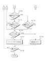
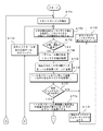
- step ST8 shown in FIG. 4 the CPU 23 branches the control based on whether the candidate character of the decoding result is the target character immediately after the margin.
- the process proceeds to step ST9, and the CPU 23 branches the control based on whether or not the candidate character of the decoding result is a stop character.
- step ST10 the CPU 23 performs error detection (parity check), and branches control based on whether or not the check digit is correct. If the check digit is correct, the reading is completed, and in step ST11, the CPU 23 outputs the barcode data D12 of the candidate character that is the decoding result.
- step ST8 if the candidate character of the decoding result is not the target character immediately after the margin, the CPU 23 proceeds to step ST12, and the CPU 23 branches the control based on whether or not the candidate character of the decoding result is a start character.
- step ST9 when the decoding result candidate character is a stop character and in step ST12 the decoding result candidate character is a start character, the CPU 23 proceeds to step ST13 shown in FIG.
- step ST13 the CPU 23 executes a decoding process for the next character (sixth back data). Thereafter, the process returns to step ST2.
- step ST10 If the candidate character of the decoding result is not the start character in step ST12 or if the check digit is incorrect in step ST10, the process proceeds to step ST14, and the CPU 23 executes a reading error process. In the reading error process, the next margin is searched.
- barcode data may be created by temporarily placing an error character.
- step ST15 the CPU 23 determines the end. For example, when a reading end command is detected for the barcode symbol reading device 100 and a reading end command is detected, the barcode symbol 1 reading control is terminated. When the reading end command is not detected, the process returns to step ST1 to repeat the above-described contents in order to continue the reading control of the bar code symbol 1.
- the extraction unit 23b extracts candidate characters by narrowing down target characters in which the number of modules of each of the 2 to 6 addition patterns obtained by the calculation unit 23a is an integer within an error of 1. Based on these assumptions, the search unit 23d compares the candidate characters of the number of modules of each 2 to 6 addition pattern extracted by the extraction unit 23b with the expected value character for evaluating the candidate character, An expected value character having the strongest correlation with the candidate character is searched.
- the barcode data D12 of the expected value character having the strongest correlation with the candidate character extracted from the plurality of target characters can be output as the decoding result when the barcode symbol 1 is read. Compared with the barcode reading method, erroneous reading of the barcode symbol 1 can be greatly prevented.
- the range of error is expanded from ⁇ 0.5 of the conventional method to ⁇ 1.0, and the number of candidate characters is increased. Then, six width data D10 for one character and five width data D10 before and after the character C1 are extracted, so that the number of modules in each of the 2 to 6 addition patterns is an integer within an error of 1. It becomes possible to extract more candidate characters narrowing down the target character as compared with the conventional method.
- the candidate character having the first strong correlation is set as the decoding result, but also the decoding result such that the probability that the second, third,... A plurality of candidate characters can be output.
- the reliability of the width data D10 can be selected by changing the threshold value when setting the error range.
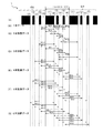
- the character C0 is provided immediately before the target character C1 shown in FIG. 5A, and the character C2 is provided immediately after the target character C1.
- Each of the characters C0 to C2 is composed of 11 modules with a full width. It consists of three bars (1), (3), (5) and three spaces (2), (4), (6).
- the number of modules in bar (1) is “4”, and the number of modules in bars (3) and (5) is “1”.
- the number of modules in the space (2) is “1”, and the number of modules in the spaces (4) and (6) is “2”. Taking the case of a barcode having these characters C0 to C2 as an example, the case of creating a target character will be described.
- W11 of the target character C1 shown in FIG. 5B is the width of the black part bar (1).
- the width of the bar (1) is counted by the counter unit 4, and the counted data value forms the width W11 data.
- W12 is the width of the space (2) following the bar (1) of the target character C1.
- the width of the space (2) is also counted by the counter unit 4, and the counted data value forms the width W12 data.
- W13 is the width of the bar (3) following the space (2) of the target character C1.
- the width of the bar (3) is counted by the counter unit 4, and the counted data value forms the width W13 data.
- W14 is the width of the space (4) following the bar (3) of the target character C1.
- the width of the space (4) is also counted by the counter unit 4, and the counted data value forms the width W14 data.
- W15 is the width of the bar (5) following the space (4) of the target character C1.
- the width of the bar (5) is counted by the counter unit 4, and the counted data value forms the width W15 data.
- W16 is the width of the space (6) following the bar (5) of the target character C1.
- the width of the space (6) is also counted by the counter unit 4, and the counted data value forms the width W16 data.
- the above-mentioned six kinds of width W11 data to width W16 data are one data of one character, and constitute the width data D10.
- W2-1 shown in FIG. 5C is a width obtained by adding the space (6) of the previous target character C0 and the bar (1) of the target character C1 by the calculation unit 23a.
- the counted data value indicating the added width of the space (6) + the bar (1) forms the width W2-1 data.
- W21 is a width obtained by adding the bar (1) and the space (2) of the target character C1 following the space (6) of the previous character C0 by the calculation unit 23a (hereinafter referred to as bar (1) + space (2). ).
- the counted data value indicating the added width of the bar (1) + the space (2) forms the width W21 data.
- W22 is a width obtained by adding the space (2) and the bar (3) following the bar (1) of the target character C1 by the calculation unit 23a.
- the counted data value indicating the added width of the space (2) + the bar (3) forms the width W22 data.
- W23 is a width obtained by adding each of the bar (3) and the space (4) following the space (2) of the target character C1 by the calculation unit 23a.
- the counted data value indicating the added width of the bar (3) + the space (4) forms the width W23 data.
- W24 is a width obtained by adding the space (4) and the bar (5) following the bar (3) of the target character C1 by the calculation unit 23a.
- the counted data value indicating the added width of the space (4) + the bar (5) forms the width W24 data.
- W25 is a width obtained by adding each of the bar (5) and the space (6) following the space (4) of the target character C1 by the calculation unit 23a.
- the counted data value indicating the added width of the bar (5) + the space (6) forms the width W25 data.
- W26 is a width obtained by adding the space (6) following the bar (5) and the bar (1) of the next character C2 by the calculation unit 23a.
- the counted data value indicating the added width of the space (6) + the bar (1) forms the width W26 data.
- the above-mentioned seven types of width W2-1 data to width W26 data are two character addition data for one character, and form width data D10.
- W3-2 shown in FIG. 5D is a width obtained by adding the bar (5), the space (6) of the previous character C0, and the bar (1) of the target character C1 by the calculation unit 23a. It is. The counted data value indicating the added width of the bar (5) + the space (6) + the bar (1) forms the width W3-2 data.
- W3-1 is a width obtained by adding the space (6) of the previous character C0, the bar (1) of the target character C1, and the space (2) by the calculation unit 23a. The counted data value indicating the added width of the space (6) + the bar (1) + the space (2) forms the width W3-1 data.
- W31 is a width obtained by adding the bar (1), the space (2), and the bar (3) of the target character C1 by the calculation unit 23a.
- the counted data value indicating the added width of the bar (1) + the space (2) + the bar (3) forms the width W31 data.
- W32 is a width obtained by adding the space (2), the bar (3), and the space (4) following the bar (1) of the target character C1 by the calculation unit 23a.
- the counted data value indicating the added width of the space (2) + the bar (3) + the space (4) forms the width W32 data.
- W33 is a width obtained by adding the bar (3), the space (4), and the bar (5) following the space (2) of the target character C1 by the calculation unit 23a.
- the counted data value indicating the added width of the bar (3) + the space (4) + the bar (5) forms the width W33 data.
- W34 is a width obtained by adding the space (4), the bar (5), and the space (6) following the bar (3) of the target character C1 by the calculation unit 23a.
- the counted data value indicating the added width of the space (4) + the bar (5) + the space (6) forms the width W34 data.
- W35 is a width obtained by adding the bar (5), the space (6) following the space (4) of the target character C1, and the bar (1) of the next character C2 by the calculation unit 23a.
- the counted data value indicating the added width of the bar (5) + the space (6) + the bar (1) forms the width W35 data.
- W36 is a width obtained by adding the bar (1) and the space (2) of the character C2 immediately following the space (6) following the bar (3) of the target character C1 by the calculation unit 23a.
- the counted data value indicating the added width of the space (6) + the bar (1) + the space (2) forms the width W36 data.
- the above-mentioned eight kinds of width W3-2 data to width W36 data are the three added data of one character, and constitute the width data D10.
- each of the bar (5), the space (6) of the previous character C0, the bar (1) and the space (2) of the target character C1 is obtained by the calculation unit 23a.
- the counted data value indicating the added width of the bar (5) + the space (6) + the bar (1) + the space (2) forms the width W4-2 data.
- W4-1 is a width obtained by adding the space (6) of the previous character C0, the bar (1), the space (2), and the bar (3) of the target character C1 by the calculation unit 23a.
- the counted data value indicating the added width of space (6) + bar (1) + space (2) + bar (3) forms width W4-1 data.
- W41 is a width obtained by adding the bar (1), the space (2), the bar (3), and the space (4) of the target character C1 by the calculation unit 23a.
- the counted data value indicating the added width of the bar (1) + the space (2) + the bar (3) + the space (4) forms the width W41 data.
- W42 is a width obtained by adding the space (2), the bar (3), the space (4), and the bar (5) following the bar (1) of the target character C1 by the calculation unit 23a.
- the counted data value indicating the added width of the space (2) + bar (3) + space (4) + bar (5) forms the width W42 data.
- W43 is a width obtained by adding the bar (3), the space (4), the bar (5), and the space (6) following the space (2) of the target character C1 by the calculation unit 23a.
- the counted data value indicating the added width of the bar (3) + the space (4) + the bar (5) + the space (6) forms the width W43 data.
- W44 is a width obtained by adding the space (4), the bar (5), the space (6) following the bar (3) of the target character C1 and the bar (1) of the next character C2 by the calculation unit 23a. It is.
- the counted data value indicating the added width of space (4) + bar (5) + space (6) + bar (1) forms the width W44 data.
- W45 is the width of the bar (5), the space (6), the bar (1) of the next character C2, and the space (2) following the white space (4) of the target character C1.
- the counted data value indicating the added width of the bar (5) + the space (6) + the bar (1) + the space (2) forms the width W45 data.
- the above-mentioned seven types of width W4-2 data to width W45 data are 4-character addition data for one character, and form width data D10.
- W5-2 shown in (F) of FIG. 5 represents each of the bar (5), the space (6), the bar (1), the space (2), and the bar (3) of the previous character C0. Is the width added by the calculation unit 23a.
- the counted data value indicating the added width of the bar (5) + the space (6) + the bar (1) + the space (2) + the bar (3) forms the width W5-2 data.
- W5-1 is a width obtained by adding the space (6) of the previous character C0 + the bar (1) of the character C1 + the space (2) + the bar (3) + the space (4) by the calculation unit 23a. It is.
- the counted data value indicating the added width of space (6) + bar (1) + space (2) + bar (3) + space (4) forms the width W5-1 data.
- W51 is a width obtained by adding each of the bar (1), the space (2), the bar (3), the space (4), and the bar (5) of the target character C1 by the calculation unit 23a.
- the counted data value indicating the added width of the bar (1) + the space (2) + the bar (3) + the space (4) + the bar (5) forms the width W51 data.
- W52 is a width obtained by adding the space (2), the bar (3), the space (4), the bar (5), and the space (6) following the bar (1) of the target character C1 by the calculation unit 23a.
- the counted data value indicating the added width of the space (2) + bar (3) + space (4) + bar (5) + space (6) forms the width W52 data.
- each of the bar (3), the space (4), the bar (5), the space (6), and the bar (1) of the next character C2 following the space (2) of the target character C1 is an arithmetic unit 23a.
- the width added by. The counted data value indicating the added width of the bar (3) + the space (4) + the bar (5) + the space (6) + the bar (1) forms the width W53 data.
- the space (4), the bar (5), the space (6) following the bar (3) of the target character C1, and the bar (1) and the space (2) of the next character C2 are calculated by the calculation unit 23a. The width added by.
- width W54 data The counted data value indicating the added width of the space (4) + bar (5) + space (6) + bar (1) + space (2) forms the width W54 data.
- the above-described six types of width W5-2 data and width W54 data are 5-character addition data for one character, and form width data D10.
- W6-2 shown in FIG. 5G is the bar (5), space (6) of the previous character C0, bar (1), space (2), bar (3) and space of the target character C1.
- Each of (4) is a width added by the calculation unit 23a.
- the counted data value indicating the added width of the bar (5) + the space (6) + the bar (1) + the space (2) + the bar (3) + the space (4) of the character C1 forms the width W6-2 data.
- each of the space (6) of the previous character C0, the bar (1), the space (2), the bar (3), the space (4), and the bar (5) of the target character C1 is an arithmetic unit.
- the counted data value indicating the added width of the space (6) + bar (1) + space (2) + bar (3) + space (4) + bar (5) forms the width W6-1 data.
- W61 is the width obtained by adding the bar (1), space (2), bar (3), space (4), bar (5), and space (6) of the target character C1 by the calculation unit 23a.
- the counted data value indicating the added width of the bar (1) + the space (2) + the bar (3) + the space (4) + the bar (5) + the space (6) forms the width W61 data.
- W62 is a space (2), a bar (3), a space (4), a bar (5), a space (6), and a bar (1) of the next character C2 following the bar (1) of the target character C1. Is the width added by the calculation unit 23a.
- the counted data value indicating the added width of the space (2) + bar (3) + space (4) + bar (5) + space (6) + bar (1) forms the width W62 data.
- W63 is a bar (3), a space (4), a bar (5), a space (6), and a bar (1) and a space (2) of the character C2 that follows the space (2) of the target character C1. Is the width added by the calculation unit 23a.
- the counted data value indicating the added width of the bar (3) + the space (4) + the bar (5) + the space (6) + the bar (1) + the space (2) forms the width W63 data.
- the above-mentioned five types of width W6-2 data and width W63 data are six-added data for one character, and form width data D10.
- width W11 data to width W16 data one data
- seven types of width W2-1 data to width W26 data two additional data
- 8 kinds of width W3-2 data to width W36 data three-piece addition data
- seven kinds of width W4-2 data to width W45 data four-piece addition data
- six kinds of width W5-2 data and width W54 39 types of target characters are obtained in total of the data (5 addition data), 5 types of width W6-2 data, and width W63 data (6 addition data).
- W11 shown in FIG. 6B is the width of the black bar (1) of the target character C1.
- the width of the bar (1) is counted by the counter unit 4, and the counted data value forms the width W11 data.
- W12 is the width of the space (2) following the bar (1) of the target character C1.
- the width of the space (2) is also counted by the counter unit 4, and the counted data value forms the width W12 data.
- W13 is the width of the bar (3) following the space (2).
- the width of the bar (3) is counted by the counter unit 4, and the counted data value forms the width W13 data.
- W14 is the width of the space (4) following the bar (3) of the target character C1.
- the width of the space (4) is also counted by the counter unit 4, and the counted data value forms the width W14 data.
- W15 is the width of the bar (5) following the space (4) of the target character C1.
- the width of the bar (5) is counted by the counter unit 4, and the counted data value forms the width W15 data.
- W16 is the width of the space (6) following the bar (5) of the target character C1.
- the width of the space (6) is also counted by the counter unit 4, and the counted data value forms the width W16 data.
- the above-mentioned six kinds of width W11 data to width W16 data are one data of one character, and constitute the width data D10.
- W2-1 shown in FIG. 6C is a width obtained by adding the space (6) of the previous character C0 and the bar (1) of the target character C1 by the calculation unit 23a.
- the counted data value indicating the added width of the space (6) + the bar (1) forms the width W2-1 data.
- W21 is the width obtained by adding the bar (1) and the space (2) following the space (6) of the previous character C0 by the calculation unit 23a (hereinafter referred to as bar (1) + space (2)). is there.
- the counted data value indicating the added width of the bar (1) + the space (2) forms the width W21 data.
- W22 is a width obtained by adding the space (2) and the bar (3) following the bar (1) of the target character C1 by the calculation unit 23a.
- the counted data value indicating the added width of the space (2) + the bar (3) forms the width W22 data.
- W23 is a width obtained by adding each of the bar (3) and the space (4) following the space (2) of the target character C1 by the calculation unit 23a.
- the counted data value indicating the added width of the bar (3) + the space (4) forms the width W23 data.
- W24 is a width obtained by adding the space (4) and the bar (5) following the bar (3) of the target character C1 by the calculation unit 23a.
- the counted data value indicating the added width of the space (4) + the bar (5) forms the width W24 data.
- W25 is a width obtained by adding the bar (5) and the space (6) following the space (4) of the target character C1 by the calculation unit 23a.
- the counted data value indicating the added width of the bar (5) + the space (6) forms the width W25 data.
- W26 is a width obtained by adding the space (6) following the bar (5) of the target character C1 and the bar (1) of the next character C2 by the calculation unit 23a.
- the counted data value indicating the added width of the space (6) + the bar (1) forms the width W26 data.
- the above-mentioned seven types of width W2-1 data to width W26 data are two character addition data for one character, and form width data D10.
- W3-2 shown in FIG. 6D is a width obtained by adding the bar (5), the space (6) of the previous character C0, and the bar (1) of the target character C1 by the calculation unit 23a. It is. The counted data value indicating the added width of the bar (5) + the space (6) + the bar (1) forms the width W3-2 data.
- W3-1 is a width obtained by adding the space (6) of the previous character C0, the bar (1) of the target character C1, and the space (2) by the calculation unit 23a. The counted data value indicating the added width of the space (6) + the bar (1) + the space (2) forms the width W3-1 data.
- W31 is a width obtained by adding the bar (1), the space (2), and the bar (3) of the target character C1 by the calculation unit 23a.
- the counted data value indicating the added width of the bar (1) + the space (2) + the bar (3) forms the width W31 data.
- W32 is a width obtained by adding the space (2), the bar (3), and the space (4) following the bar (1) of the target character C1 by the calculation unit 23a.
- the counted data value indicating the added width of the space (2) + the bar (3) + the space (4) forms the width W32 data.
- W33 is a width obtained by adding the bar (3), the space (4), and the bar (5) following the space (2) of the target character C1 by the calculation unit 23a.
- the counted data value indicating the added width of the bar (3) + the space (4) + the bar (5) forms the width W33 data.
- W34 is a width obtained by adding the space (4), the bar (5), and the space (6) following the bar (3) by the calculation unit 23a.
- the counted data value indicating the added width of the space (4) + the bar (5) + the space (6) forms the width W34 data.
- W35 is a width obtained by adding the bar (5), the space (6) following the space (4) of the target character C1, and the bar (1) of the next character C2 by the calculation unit 23a.
- the counted data value indicating the added width of the bar (5) + the space (6) + the bar (1) forms the width W35 data.
- W36 is a width obtained by adding the bar (1) and the space (2) of the character C2 immediately following the space (6) following the bar (3) of the target character C1 by the calculation unit 23a.
- the counted data value indicating the added width of the space (6) + the bar (1) + the space (2) forms the width W36 data.
- the above-mentioned eight kinds of width W3-2 data to width W36 data are the three added data of one character, and constitute the width data D10.
- W4-3 shown in FIG. 6E, the space (4), bar (5), space (6), and bar (1) of the previous character C0 are added by the arithmetic unit 23a. Width.
- the counted data value indicating the added width of space (4) + bar (5) + space (6) + bar (1) forms the width W4-3 data.
- W4-2 is a width obtained by adding the bar (5), space (6), and bar (1) and space (2) of the target character C1 by the calculation unit 23a.
- the counted data value indicating the added width of the bar (5) + the space (6) + the bar (1) + the space (2) forms the width W4-2 data.
- W4-1 is a width obtained by adding the space (6) of the previous character C0, the bar (1), the space (2), and the bar (3) of the target character C1 by the calculation unit 23a.
- the counted data value indicating the added width of space (6) + bar (1) + space (2) + bar (3) forms width W4-1 data.
- W41 is a width obtained by adding the bar (1), the space (2), the bar (3), and the space (4) of the target character C1 by the calculation unit 23a.
- the counted data value indicating the added width of the bar (1) + the space (2) + the bar (3) + the space (4) forms the width W41 data.
- W42 is a width obtained by adding the space (2), the bar (3), the space (4), and the bar (5) following the bar (1) of the target character C1 by the calculation unit 23a.
- the counted data value indicating the added width of the space (2) + bar (3) + space (4) + bar (5) forms the width W42 data.
- W43 is a width obtained by adding the bar (3), the space (4), the bar (5), and the space (6) following the space (2) of the target character C1 by the calculation unit 23a.
- the counted data value indicating the added width of the bar (3) + the space (4) + the bar (5) + the space (6) forms the width W43 data.
- W44 is a width obtained by adding the space (4), the bar (5), the space (6) following the bar (3) of the target character C1 and the bar (1) of the next character C2 by the calculation unit 23a. It is.
- the counted data value indicating the added width of space (4) + bar (5) + space (6) + bar (1) forms the width W44 data.
- W45 the bar (5), the space (6) following the white space (4) of the target character C1, the bar (1) of the next character C2, and the space (2) are added by the calculation unit 23a. Width.
- the counted data value indicating the added width of the bar (5) + the space (6) + the bar (1) + the space (2) forms the width W45 data.
- W46 is a width obtained by adding the space (6) following the bar (5) of the target character C1 and the bar (1), space (2), and bar (3) of the next character C2 by the calculation unit 23a. It is.
- the counted data value indicating the added width of space (6) + bar (1) + space (2) + bar (3) forms the width W46 data.
- the above-mentioned nine types of width W4-3 data to width W46 data are 4-character addition data for one character, and form width data D10.
- W5-4 shown in FIG. 6 (F) indicates that each of the bar (3), the space (4), the bar (5), the space (6) and the bar (1) of the character C1 of the previous character C0 This is the width added by the calculation unit 23a.
- the counted data value indicating the added width of the bar (3) + space (4) + bar (5) + space (6) + bar (1) forms the width W5-4 data.
- the space (4), bar (5), space (6) of the previous character C0, and the bar (1) and space (2) of the target character C1 are added by the calculation unit 23a. Width.
- the counted data value indicating the added width of space (4) + bar (5) + space (6) + bar (1) + space (2) forms width W5-3 data.
- the bar (5), the space (6) of the previous character C0, the bar (1), the space (2), and the bar (3) of the target character C1 are added by the calculation unit 23a. Width.
- the counted data value indicating the added width of the bar (5) + the space (6) + the bar (1) + the space (2) + the bar (3) forms the width W5-2 data.
- the space (6) of the previous character C0, the bar (1), the space (2), the bar (3), and the space (4) of the target character C1 are added by the arithmetic unit 23a.
- Width The counted data value indicating the added width of space (6) + bar (1) + space (2) + bar (3) + space (4) forms the width W5-1 data.
- W51 is a width obtained by adding each of the bar (1), the space (2), the bar (3), the space (4), and the bar (5) of the target character C1 by the calculation unit 23a.
- the counted data value indicating the added width of the bar (1) + the space (2) + the bar (3) + the space (4) + the bar (5) forms the width W51 data.
- W52 is a width obtained by adding the space (2), the bar (3), the space (4), the bar (5), and the space (6) following the bar (1) of the target character C1 by the calculation unit 23a.
- the counted data value indicating the added width of the space (2) + bar (3) + space (4) + bar (5) + space (6) forms the width W52 data.
- each of the bar (3), the space (4), the bar (5), the space (6), and the bar (1) of the next character C2 following the space (2) of the target character C1 is an arithmetic unit 23a.
- the width added by. The counted data value indicating the added width of the bar (3) + the space (4) + the bar (5) + the space (6) + the bar (1) forms the width W53 data.
- the space (4), the bar (5), the space (6) following the bar (3) of the target character C1, and the bar (1) and the space (2) of the next character C2 are calculated by the calculation unit 23a.
- the counted data value indicating the added width of the space (4) + bar (5) + space (6) + bar (1) + space (2) forms the width W54 data.
- the bar (5), the space (6) following the space (4) of the target character C1, the bar (1), the space (2), and the bar (3) of the next character C2 are each an arithmetic unit.
- the counted data value indicating the added width of the bar (5) + the space (6) + the bar (1) + the space (2) + the bar (3) forms the width W55 data.
- the space (6) following the bar (5) of the target character C1 and the bar (1), the space (2), the bar (3), and the space (4) of the next character C2 are calculated by the calculation unit 23a.
- the counted data value indicating the added width of the space (6) + bar (1) + space (2) + bar (3) + space (4) forms the width W56 data.
- the 10 types of width W5-4 data and width W56 data described above are 5-character addition data for one character, and form width data D10.
- W6-5 shown in FIG. 6G is the space (2), bar (3), space (4), bar (5), space (6), and character C1 of the previous character C0.
- Each of the bars (1) is the width added by the calculation unit 23a.
- the counted data value indicating the added width of space (2) + bar (3) + space (4) + bar (5) + space (6) + bar (1) forms width W6-5 data.
- each of the bar (3), space (4), bar (5), space (6), and bar (1) and space (2) of the target character C1 is the calculation unit.
- the width added by 23a The counted data value indicating the added width of the bar (3) + space (4) + bar (5) + space (6) + bar (1) + space (2) forms the width W6-4 data.
- the space (4), bar (5), space (6) of the previous character C0, the bar (1), the space (2) and the bar (3) of the target character C1 are each an arithmetic unit.
- the counted data value indicating the added width of space (4) + bar (5) + space (6) + bar (1) + space (2) + bar (3) forms the width W6-3 data.
- the bar (5) + space (6) of the previous character C0 + the bar (1) + space (2) + bar (3) + space (4) of the character C1 is calculated by the calculation unit 23a.
- the counted data value indicating the added width of the bar (5) + the space (6) + the bar (1) + the space (2) + the bar (3) + the space (4) of the character C1 forms the width W6-2 data.
- the space (6) of the previous character C0 + the bar (1) of the character C1 + the space (2) + the bar (3) + the space (4) + the bar (5) is calculated by the calculation unit 23a.
- the counted data value indicating the added width of the space (6) + the character C1 bar (1) + the space (2) + the bar (3) + the space (4) + the bar (5) forms the width W6-1 data.
- W61 is the width obtained by adding the bar (1), space (2), bar (3), space (4), bar (5), and space (6) of the target character C1 by the calculation unit 23a.
- the counted data value indicating the added width of the bar (1) + the space (2) + the bar (3) + the space (4) + the bar (5) + the space (6) forms the width W61 data.
- W62 is the space (2), bar (3), space (4), bar (5), space (6) following the bar (1) of the target character C1, and the bar (1) of the next character C2
- Each is a width added by the calculation unit 23a.
- the counted data value indicating the added width of the space (2) + bar (3) + space (4) + bar (5) + space (6) + bar (1) forms the width W62 data.
- W63 is a bar (3), a space (4), a bar (5), a space (6), and a bar (1) and a space (2) of the character C2 that follows the space (2) of the target character C1. Is the width added by the calculation unit 23a.
- the counted data value indicating the added width of the bar (3) + the space (4) + the bar (5) + the space (6) + the bar (1) + the space (2) forms the width W63 data.
- W64 is the space (4), bar (5), space (6) following the bar (3) of the target character C1, and the bar (1), space (2), and bar (3) of the next character C2.
- Each is a width added by the calculation unit 23a.
- the counted data value indicating the added width of the bar (1) + the space (2) + the bar (3) of the space (4) + bar (5) + space (6) +1 next character C2 forms the width W64 data.
- W65 includes the bar (5), the space (6) following the space (4) of the target character C1, the bar (1), the space (2), the bar (3) and the space (4) of the next character C2.
- Each is a width added by the calculation unit 23a.
- the counted data value indicating the added width of the bar (5) + the space (6) +1 and the bar (1) + the space (2) + the bar (3) + the space (4) of the next character C2 forms the width W65 data.
- W66 is the space (6) following the bar (5) of the target character C1, the bar (1), the space (2), the bar (3), the space (4) and the bar (5) of the next character C2.
- Each is a width added by the calculation unit 23a.
- the counted data value indicating the added width of the bar (1) + the space (2) + the bar (3) + the space (4) + the bar (5) of the space (6) +1 next character C2 forms the width W66 data.
- the eleven types of width W6-5 data and width W66 data described above are 6-character addition data for one character, and form width data D10.
- width W11 data to width W16 data one data
- seven types of width W2-1 data to width W26 6 types.
- Data (2 added data) 8 types of width W3-2 data to width W36 data (3 added data)
- 9 types of width W4-3 data to W46 data 4 added data
- 10 types of width A total of 51 types of target characters is obtained from the total of W5-4 data, width W56 data (5 addition data), and 11 types of width W6-5 data and width W66 data (6 addition data).
- FIG. 7A to FIG. 7C an example of the barcode symbol of CODE128, an example of its loss, and an example of its reconstruction will be described.
- the bar code symbol 1 of CODE 128 shown in FIG. 7A does not have any missing or scratched bars or spaces.
- the barcode symbol 1 is composed of 8 characters.
- the barcode data D12 expresses the number “123455678”.
- the bar code symbol 1 'of CODE128 shown in FIG. 7B is a bar, space, or the like that is missing or damaged. Assume that the bar code symbol 1 'occurs in the bar code symbol 1 of CODE 128 shown in FIG. 7A. Three horizontal broken lines in the figure are threshold values th1 to th3. The respective thresholds th1 to th3 are set at the upper, middle and lower stages orthogonal to the scanning direction.
- barcode data D12 indicating “12 ?? 5678” is output as a decoding result based on the threshold value th1.
- “3” and “4” are not decoded.
- bar code data D12 indicating “12 ??? 78” is output.
- “3” to “6” are not decoded.
- barcode data D12 indicating “123456 ??” is output. “7” and “8” are not decoded.
- scanning is performed one after another in the upper, middle, and lower stages orthogonal to the scanning direction, error characters are corrected, CD (check digit) verification is performed when there are no more error characters, and bar code data D12. Was created.
- CD check digit
- the width W11 data of the bar (1) of the target character C1 is used only in the addition width W21 when calculating the two-piece addition pattern, but the width W12 data of the space (2) is used when calculating the two-piece addition pattern.
- the addition width W21 and the addition width W22 are used. Therefore, in the second embodiment, the calculation is performed including the element portion including the characters C0 and C2 adjacent to the character C1.
- the pattern recognition addition range is extended to two-character elements on both sides.
- the addition range is expanded to 5 elements of space (6), bar (5), space (4), bar (3) and space (2) of the previous character C0 adjacent to the target character shown in FIG. 7A.
- the next character C2 is expanded to five elements of the bar (1), the space (2), the bar (3), the space (4), and the bar (5). It is assumed that decoding results are obtained from 51 types of target characters by expanding the addition range (multi-scan recontraction).
- the CPU 23 searches for a start margin in step ST21 of the flowchart shown in FIG.
- the optical reading unit 2 reads the barcode symbol 1 and generates the code reading data D2 in the same manner as in the first embodiment.
- the code reading data D2 is output from the optical reading unit 2 to the counter unit 4.
- the clock generator 3 outputs a sampling signal CLK signal having a predetermined frequency to the counter unit 4.
- the counter unit 4 receives the code reading data D2 output from the optical reading unit 2, and also receives the CLK signal output from the clock generation unit 3, counts the code reading data D2 based on the CLK signal, and reads the code.
- the data D2 is converted into count data D4 indicating the width of one element and the addition width of two elements including a white space and a black bar.
- the count data D4 is a numerical data string indicating the width of each bar (black part) and the width of a space (white part) in the barcode symbol 1.
- the count data D4 is stored in the width data storage unit 10. Note that the description of the search for the start margin is omitted.
- step ST22 the CPU 23 extracts width data (6 pieces) for one character.
- the width W11 of the black portion bar (1) is counted by the counter unit 4, and the counted data value becomes the width W11 data.
- the width W12 of the white space (2) following the bar (1) is also counted by the counter unit 4, and the counted data value becomes the width W12 data.
- the width W13 of the bar (3) following the space (2) is counted by the counter unit 4, and the counted data value becomes the width W13 data.
- the width W14 of the space (4) following this bar (3) is also counted by the counter unit 4, and the counted data value becomes the width W14 data.
- the width W15 of the bar (5) following the space (4) is counted by the counter unit 4, and the counted data value becomes the width W15 data.
- the width W16 of the space (6) following the bar (5) is also counted by the counter unit 4, and the counted data value becomes the width W16 data.
- the above-described six types of width W11 data to width W16 data constitute the barcode data value D30.
- the barcode data value D30 is output to the CPU 23 via the interface unit 11.
- step ST23 the CPU 23 branches the control based on the presence / absence of bar division and disappearance.
- the total of the six widths is compared with the width of one character, and it is determined whether the width data D10 for one character is appropriate.
- a total value obtained by adding the widths of six elements including adjacent bars and spaces in one character is compared with a full width value indicating the full width of one character, and the width for one character is determined based on the comparison result. It is determined whether or not the data D10 is appropriate.
- the CPU 23 compares the width of six bars (1), spaces (2), bars (3), spaces (4), bars (5) and spaces (6) adjacent to each other in one character.
- the total of W1 to W6 is compared with the full width value indicating the full width of one character. Based on the comparison result by the comparison unit 23c, it is possible to determine whether or not the width data D10 for one character is appropriate. Based on this determination, it is possible to determine disappearance or division of the character bar.
- the character frame can be determined from the full widths of the characters C0 and C2 before and after the character C1, the decoding can be continued even if there are excess or deficiency in elements such as voids and spots.
- the target character can be narrowed down based on the determination result such as disappearance or division of the bar, the calculation amount can be reduced, and the processing time can be increased.
- the CPU 23 calculates one module width in step ST24 and stores one character width.
- the computing unit 23a calculates the one module width of the character C1 based on the six types of width W11 data to width W16 data.
- the width of one character is the width of six bars (1), space (2), bar (3), space (4), bar (5) and space (6) adjacent to each other in one character shown in FIG. 7B. It is obtained by summing W1 to W6.
- step ST25 the CPU 23 converts the width data D10 for one character into a two-piece addition pattern. For example, the counted data value indicating the added width W2-1 in which the space (6) of the previous character C0 and the bar (1) of the target character C1 shown in FIG. -1 data.
- the counted data value indicating the added width W21 obtained by adding the bar (1) and the space (2) following the space (6) of the previous character C0 by the calculation unit 23a is the width W21 data.
- the counted data value indicating the added width W22 obtained by adding the space (2) and the bar (3) following the bar (1) of the target character C1 by the calculation unit 23a becomes the width W22 data.
- the counted data value indicating the added width W23 obtained by adding the bar (3) and the space (4) following the space (2) of the target character C1 by the calculation unit 23a is the width W23 data.
- the counted data value indicating the added width W24 obtained by adding the space (4) and the bar (5) following the bar (3) of the target character C1 by the calculation unit 23a is the width W24 data.
- the counted data value indicating the added width W25 obtained by adding the bar (5) and the space (6) following the space (4) of the target character C1 by the calculation unit 23a is the width W25 data.
- the counted data value indicating the added width W26 obtained by adding the space (4) following the bar (3) of the target character C1 and the bar (1) of the next character C2 by the calculation unit 23a becomes the width W26 data.
- the above-mentioned seven types of width W2-1 data to width W26 data are two-element added data of one character and are composed of width data D10.
- step ST26 the CPU 23 searches for a character that matches the previously converted two-addition pattern.
- the search unit 23d performs six types of width W11 data to width W16 data (one piece of data) and seven types of width W2-. 1 data to width W26 data (2 added data), 8 types of width W3-2 data to width W36 data (3 added data), 9 types of width W4-3 data to width W46 data (4 added data) 10 types of width W5-4 data and width W56 data (5 additional data) and 11 types of width W6-5 data and width W66 data (6 additional data) match 51 types of target character C1. Search for the character you want. At that time, a target character that matches one of the two types of target characters with respect to the width of each element is searched to narrow down the target characters. By this narrowing down, about 1 to 4 candidate characters are searched.
- step ST27 the CPU 23 branches the control based on the presence / absence of a matching character. If there is a matching character, in step ST28, the target character whose two added patterns match is taken as the decoding result. Thereafter, the process proceeds to step ST31 shown in FIG.
- step ST23 if there is a division or disappearance of a bar, and if there is no matching character in step ST27, the CPU 23 sets the current character as an error character in step ST29. Thereafter, in step ST30, the CPU 23 proceeds to a decoding process for the next character (data after one character width). Thereafter, the process proceeds to step ST22, and the above-described contents are repeated.
- step ST31 shown in FIG. 9 the CPU 23 branches the control based on whether or not the character is immediately after the margin. If the candidate character that is the decoding result is not the character immediately after the margin, the process proceeds to step ST32, and the CPU 23 branches the control based on whether or not the decoding result is a stop character. When the decoding result is a stop character, the process proceeds to step ST33, and the CPU 23 branches the control based on whether or not an error character exists in the decoding result.
- step ST34 the CPU 23 overwrites the decoding result of the current (current) scan in the decoding buffer 25. Thereafter, the process proceeds to step ST35, where the CPU 23 performs error detection (parity check) and branches control based on whether or not the check digit is correct. If the check digit is correct, the CPU 23 completes reading in step ST36, outputs the barcode data D12 of the decode buffer 25, and clears the decode buffer 25 (normal end). Thereafter, the process proceeds to step ST45.
- step ST35 the CPU 23 performs error detection (parity check) and branches control based on whether or not the check digit is correct. If the check digit is correct, the CPU 23 completes reading in step ST36, outputs the barcode data D12 of the decode buffer 25, and clears the decode buffer 25 (normal end). Thereafter, the process proceeds to step ST45.
- step ST37 the CPU 23 branches the control based on whether or not the decoding result is a start character.
- step ST38 the CPU 23 decodes the next character (sixth back width data D10). Thereafter, the process returns to step ST22.
- step ST33 the CPU 23 branches control in step ST39 shown in FIG. 10 based on whether or not the length of the decoding buffer 25 is equal to the decoding data length. If the length of the decode buffer 25 is equal to the decode data length, the data is rewritten if the error character portion of the decode buffer 25 is successfully decoded in step ST41. Thereafter, the process proceeds to step ST42, and the control branches based on whether or not there is an error character in the decode buffer 25. If there is no error character in the decode buffer 25, the process returns to step ST35.
- step ST35 If the check digit is incorrect in step ST35 described above, the decoding buffer 25 is cleared in step ST43 shown in FIG. 10, and then the decoding result is not a start character in step ST37 shown in FIG. If the length of the decode buffer 25 is different from the decode data length in step ST39, the decode buffer 25 is cleared in step ST40, and if an error character exists in the decode buffer 25 in step ST42, the process proceeds to step ST44. After shifting, the CPU 23 executes read error processing. In the reading error process, the next margin is searched.
- barcode data may be created by temporarily placing an error character. Thereafter, the process proceeds to step ST45 shown in FIG. 9, and the CPU 23 determines the end. For example, when a reading end command is detected for the barcode symbol reading device 100 and a reading end command is detected, the barcode symbol 1 reading control is terminated. When the reading end command is not detected, the process returns to step ST21 to repeat the above-described contents in order to continue the reading control of the bar code symbol 1.
- the pattern recognition addition range is extended to the elements of the two characters C0 and C2 on both sides of the target character. That is, regarding the addition range, five elements of the space (6), the bar (5), the space (4), the bar (3), and the space (2) of the immediately preceding character C0 adjacent to the target character shown in FIG. 7A. And expanded to 5 elements of bar (1), space (2), bar (3), space (4) and bar (5) of the next character C2, so 51 types of target characters It becomes possible to determine a candidate character as a decoding result from among the above.
- the part including the elements of the two characters C0 and C2 on both sides of the target character is also included in the calculation, so Even patterns with many errors such as missing or scratches are difficult to misread.
- the maximum width error of elements such as bars and spaces is ⁇ 0.5 modules or more, the possibility of being recognized as a character is increased.
- the amount of calculation can be reduced, the time required for the pattern recognition processing is shortened, and the data processing speed is increased.
- a process that combines the character decoding algorithm described in the first embodiment and the multi-scan retraction described in the second embodiment is performed.
- the start margin is searched in step ST51 of the flowchart shown in FIG.
- the optical reading unit 2 reads the barcode symbol 1 and generates the code reading data D2 in the same manner as in the first embodiment.
- the code reading data D2 is output from the optical reading unit 2 to the counter unit 4.
- the clock generator 3 outputs a sampling signal CLK signal having a predetermined frequency to the counter unit 4.
- the counter unit 4 receives the code reading data D2 output from the optical reading unit 2, and also receives the CLK signal output from the clock generation unit 3, counts the code reading data D2 based on the CLK signal, and reads the code.
- the data D2 is converted into count data D4 indicating the width of one element and the addition width of two elements including a white space and a black bar.
- the count data D4 is a numerical data string indicating the width of each bar (black part) and the width of a space (white part) in the barcode symbol 1.
- the count data D4 is stored in the width data storage unit 10. Note that the description of the search for the start margin is omitted.
- step ST52 the CPU 23 compares the total of the six widths with the width of one character, and determines whether the width data D10 for one character is appropriate.
- a total value obtained by adding the widths of six elements including adjacent bars and spaces in one character is compared with a full width value indicating the full width of one character, and the width for one character is determined based on the comparison result. It is determined whether or not the data D10 is appropriate.
- the CPU 23 compares the width of six bars (1), spaces (2), bars (3), spaces (4), bars (5) and spaces (6) adjacent to each other in one character.
- the total of W1 to W6 is compared with the full width value indicating the full width of one character. Based on the comparison result by the comparison unit 23c, it can be determined whether or not the width data D10 for one character is appropriate. Based on this determination, the character candidates can be narrowed down, the calculation amount can be reduced, and the processing time can be increased. Connected.
- step ST53 the CPU 23 branches the control based on the presence / absence of bar division and disappearance.
- the comparison result by the comparison unit 23c is used. Since the character frame can be determined from the full widths of the characters C0 and C2 before and after the target character C1, decoding can be continued even if there are excess or deficiency in elements such as voids and spots.
- the CPU 23 calculates one module width and stores one character width in step ST54. At this time, the calculation unit 23a calculates the one module width of the target character C1 based on the six types of width W11 data to width W16 data.
- the width of one character is the width of six bars (1), space (2), bar (3), space (4), bar (5) and space (6) adjacent to each other in one character shown in FIG. 7B. It is obtained by summing W1 to W6.
- step ST55 the CPU 23 converts the extracted 21 types of width data D10 into 1 to 6 added patterns (element width).
- six types of width W11 data to width W16 data are converted into single data of one character, and a single pattern is created as a recognized pattern of the target character C1 based on the single data.
- Five types of width W21 data to width W25 data are converted into double addition data of one character, and a double addition pattern (recognized pattern) of the target character C1 based on the double addition data is created.
- the four types of the width W31 data to the width W34 data are converted into the three added data of one character, and the three added knowledge pattern of the target character C1 based on the three added data is created.
- width W41 data to width W43 data are converted into 4-character addition data of one character, and a 4-addition pattern of the target character C1 based on the 4-addition data is created.
- the two types of width W51 data and width W52 data are converted into 5-character addition data for one character, and a 5-character addition pattern for the target character is created based on the 5-addition data.
- One type of width W61 data is converted into six character addition data of one character, and a six character addition pattern of the target character C4 based on the six character addition data is created.
- step ST56 in order to narrow down the characters, the CPU 23 searches for characters having an error in the number of modules within 1 for all of the 1 pattern and 2-6 addition patterns, and determines candidate characters.
- the extraction unit 23b narrows down the target characters C1 and the like whose number of modules of the one pattern and the two to six addition patterns obtained by the calculation unit 23a are integers within an error of 1, and the like. Extract.
- the extraction unit 23b obtains the six width data D10 for one character of the one pattern and the two to six addition patterns obtained by the calculation unit 23a, and (6-1) data before and after the target character. Width data D10 is extracted.
- step ST57 the CPU 23 branches the control based on whether one or more candidate characters exist. If one or more (multiple) candidate characters are present, an error between the actual value of the 1 to 6 addition pattern and its ideal value is calculated in step ST58, and the candidate character whose sum of errors is minimized. Is the decoding result.
- the candidate character having the smallest error value is the character having the strongest correlation with the expected value character. In this example, the target character C1 or the like with the smallest overall error can be selected as a candidate character.
- the CPU 23 reads the expected value character (theoretical value) from the expected value storage unit 24 to the comparison unit 23c of the CPU 23.
- the comparison unit 23c compares the candidate characters of the number of modules of each 2 to 6 addition pattern (element width) extracted by the extraction unit 23b with an expected value character (theoretical value) for evaluating the candidate character. .
- the comparison result is output to the search unit 23d.
- the search unit 23d searches for an expected value character having the strongest correlation with the candidate character. For example, when the above-described calculation unit 23a calculates an error between the measured value of the number of modules of the candidate character and the ideal value of the number of modules of the expected value character, the search unit 23d calculates the error calculated by the calculation unit 23a. An expected value character having the strongest correlation with the candidate character having the smallest error value obtained by summing is searched.
- step ST57 the current character is set as an error character in step ST59. Thereafter, in step ST60, the process proceeds to a decoding process for the next character (data after the character width).
- step ST61 shown in FIG. 12 the CPU 23 branches the control based on whether or not it is the target character immediately after the margin. If the candidate character that is the decoding result is not the target character immediately after the margin, the process proceeds to step ST62, and the CPU 23 branches the control based on whether or not the decoding result is a stop character. When the decoding result is a stop character, the process proceeds to step ST63, and the CPU 23 branches the control based on whether or not an error character exists in the decoding result.
- step ST64 If there is no error character in the decoding result, the process proceeds to step ST64, and the CPU 23 overwrites the decoding result of the current (current) scan in the decoding buffer 25. Thereafter, the process proceeds to step ST65, where the CPU 23 executes error detection (parity check) and branches the control based on whether or not the check digit is correct. If the check digit is correct, the CPU 23 completes reading in step ST66, outputs the barcode data D12 of the decode buffer 25, and clears the decode buffer 25 (normal end). Thereafter, the process proceeds to step ST65.
- error detection parity check
- step ST67 the CPU 23 branches the control based on whether or not the decoding result is a start character.
- step ST68 the CPU 23 executes a decoding process for the next character (sixth back width data D10). Thereafter, the process returns to step ST52.
- step ST63 the CPU 23 branches control in step ST69 shown in FIG. 13 based on whether or not the length of the decoding buffer 25 is equal to the decoding data length. If the length of the decode buffer 25 is equal to the decode data length, the data is rewritten if the error character portion of the decode buffer 25 is successfully decoded in step ST71. Thereafter, the process proceeds to step ST72, and the control is branched based on whether or not an error character exists in the decode buffer 25. If there is no error character in the decode buffer 25, the process returns to step ST65.
- step ST65 If the check digit is incorrect in step ST65 described above, the decoding buffer 25 is cleared in step ST73 shown in FIG. 13 and then the decoding result is not a start character in step ST67 shown in FIG. If the length of the decode buffer 25 is different from the decode data length in step ST69, the decode buffer 25 is cleared in step ST70, and if an error character exists in the decode buffer 25 in step ST72, the process goes to step ST74. After shifting, the CPU 23 executes read error processing. In the reading error process, the next margin is searched.
- barcode data may be created by temporarily placing an error character. Thereafter, the process proceeds to step ST75 shown in FIG. 12, and the CPU 23 determines the end. For example, when a reading end command is detected for the barcode symbol reading device 100 and a reading end command is detected, the barcode symbol 1 reading control is terminated. If the reading end command is not detected, the process returns to step ST51 to repeat the above-described contents in order to continue the reading control of the bar code symbol 1.
- the search unit 23d compares the candidate characters of the number of modules of each 2 to 6 addition pattern extracted by the extraction unit 23b with the expected value character for evaluating the candidate character, An expected value character having the strongest correlation with the candidate character is searched.
- the barcode data D12 of the expected value character having the strongest correlation with the candidate character extracted from the plurality of target characters can be output as the decoding result when the barcode symbol 1 is read. Compared with the barcode reading method, erroneous reading of the barcode symbol 1 can be greatly prevented.
- the range of error is expanded from ⁇ 0.5 of the conventional method to ⁇ 1.0, and the target character is increased. Since 6 width data D10 for one character and 5 width data D10 before and after the target character are extracted, the number of modules in each of the 2 to 6 addition patterns becomes an integer within 1 error. More candidate characters can be extracted by narrowing down the target characters compared to the conventional method. Further, by narrowing down the candidate characters, the amount of calculation can be reduced, the time required for the pattern recognition process is shortened, and the data processing speed is increased. As a result, it is possible to largely prevent erroneous barcode reading as compared with the conventional barcode reading method. Note that the reliability of the width data D10 can be selected by changing the threshold value when setting the error range.
- the present invention is extremely suitable when applied to a barcode symbol reader that reads barcode symbols and outputs barcode data.
Landscapes
- Engineering & Computer Science (AREA)
- Physics & Mathematics (AREA)
- General Physics & Mathematics (AREA)
- Theoretical Computer Science (AREA)
- Health & Medical Sciences (AREA)
- Electromagnetism (AREA)
- General Health & Medical Sciences (AREA)
- Toxicology (AREA)
- Artificial Intelligence (AREA)
- Computer Vision & Pattern Recognition (AREA)
- Quality & Reliability (AREA)
- Character Discrimination (AREA)
Priority Applications (3)
| Application Number | Priority Date | Filing Date | Title |
|---|---|---|---|
| EP12749609.9A EP2680186B1 (en) | 2011-02-21 | 2012-02-20 | Optical information reading device, optical information reading method, computer-readable program, and recording medium |
| CN201280009825.9A CN103403735B (zh) | 2011-02-21 | 2012-02-20 | 光学信息读取装置、光学信息读取方法 |
| US13/972,422 US9361504B2 (en) | 2011-02-21 | 2013-08-21 | Optical information reading device, optical information reading method, computer-readable program and recording medium |
Applications Claiming Priority (2)
| Application Number | Priority Date | Filing Date | Title |
|---|---|---|---|
| JP2011035162A JP5800525B2 (ja) | 2011-02-21 | 2011-02-21 | 光学情報読取装置、光学情報読取方法、コンピュータが読み取り可能なプログラム及び記録媒体 |
| JP2011-035162 | 2011-02-21 |
Related Child Applications (1)
| Application Number | Title | Priority Date | Filing Date |
|---|---|---|---|
| US13/972,422 Continuation-In-Part US9361504B2 (en) | 2011-02-21 | 2013-08-21 | Optical information reading device, optical information reading method, computer-readable program and recording medium |
Publications (1)
| Publication Number | Publication Date |
|---|---|
| WO2012115046A1 true WO2012115046A1 (ja) | 2012-08-30 |
Family
ID=46720823
Family Applications (1)
| Application Number | Title | Priority Date | Filing Date |
|---|---|---|---|
| PCT/JP2012/053992 Ceased WO2012115046A1 (ja) | 2011-02-21 | 2012-02-20 | 光学情報読取装置、光学情報読取方法、コンピュータが読み取り可能なプログラム及び記録媒体 |
Country Status (5)
| Country | Link |
|---|---|
| US (1) | US9361504B2 (OSRAM) |
| EP (1) | EP2680186B1 (OSRAM) |
| JP (1) | JP5800525B2 (OSRAM) |
| CN (1) | CN103403735B (OSRAM) |
| WO (1) | WO2012115046A1 (OSRAM) |
Cited By (1)
| Publication number | Priority date | Publication date | Assignee | Title |
|---|---|---|---|---|
| JP2016151800A (ja) * | 2015-02-16 | 2016-08-22 | 株式会社ウェルキャット | コード読取学習システム |
Families Citing this family (5)
| Publication number | Priority date | Publication date | Assignee | Title |
|---|---|---|---|---|
| US9716711B2 (en) * | 2011-07-15 | 2017-07-25 | Pagemark Technology, Inc. | High-value document authentication system and method |
| CN104138208A (zh) * | 2013-05-10 | 2014-11-12 | 上海天泰茶业科技有限公司 | 饮品原料杯、读取装置、饮品制备机、饮品制备系统及其饮品制备方法 |
| JP5819925B2 (ja) * | 2013-12-25 | 2015-11-24 | ウイングアーク1st株式会社 | コード読取装置およびコード読取用プログラム |
| JP5968963B2 (ja) * | 2014-08-28 | 2016-08-10 | Idec株式会社 | 光学情報読み取り装置 |
| EP3982286B1 (en) * | 2020-10-07 | 2024-12-25 | Siemens Sanayi ve Ticaret A. S. | Computer-implemented method and device for reconstructing a barcode |
Citations (5)
| Publication number | Priority date | Publication date | Assignee | Title |
|---|---|---|---|---|
| JPS63155381A (ja) * | 1986-12-19 | 1988-06-28 | Fujitsu Kiden Ltd | バ−コ−ド復調方式 |
| JPH0636065A (ja) * | 1992-07-14 | 1994-02-10 | Fujitsu Ltd | バーコード読取復調方法 |
| JPH10187874A (ja) * | 1996-12-26 | 1998-07-21 | Matsushita Electric Ind Co Ltd | バーコードリーダおよびバーコード読み取り方法および記録媒体 |
| JP2005128626A (ja) * | 2003-10-21 | 2005-05-19 | Denso Wave Inc | バーコード読取装置及びバーコード判別方法 |
| JP4555952B2 (ja) | 2000-03-08 | 2010-10-06 | 株式会社オプトエレクトロニクス | バーコード記号読取装置及びそれによるスタートマージン候補検出方法並びにバーコード記号読取方法 |
Family Cites Families (2)
| Publication number | Priority date | Publication date | Assignee | Title |
|---|---|---|---|---|
| JPH07234905A (ja) * | 1994-02-22 | 1995-09-05 | Fujitsu Ltd | バーコード作成方法及びデータ設定方法並びに端末装置 |
| JPH11353703A (ja) * | 1998-04-06 | 1999-12-24 | Seitai Hikari Joho Kenkyusho:Kk | 情報記録媒体および情報読取システム |
-
2011
- 2011-02-21 JP JP2011035162A patent/JP5800525B2/ja not_active Expired - Fee Related
-
2012
- 2012-02-20 CN CN201280009825.9A patent/CN103403735B/zh not_active Expired - Fee Related
- 2012-02-20 EP EP12749609.9A patent/EP2680186B1/en not_active Not-in-force
- 2012-02-20 WO PCT/JP2012/053992 patent/WO2012115046A1/ja not_active Ceased
-
2013
- 2013-08-21 US US13/972,422 patent/US9361504B2/en active Active
Patent Citations (5)
| Publication number | Priority date | Publication date | Assignee | Title |
|---|---|---|---|---|
| JPS63155381A (ja) * | 1986-12-19 | 1988-06-28 | Fujitsu Kiden Ltd | バ−コ−ド復調方式 |
| JPH0636065A (ja) * | 1992-07-14 | 1994-02-10 | Fujitsu Ltd | バーコード読取復調方法 |
| JPH10187874A (ja) * | 1996-12-26 | 1998-07-21 | Matsushita Electric Ind Co Ltd | バーコードリーダおよびバーコード読み取り方法および記録媒体 |
| JP4555952B2 (ja) | 2000-03-08 | 2010-10-06 | 株式会社オプトエレクトロニクス | バーコード記号読取装置及びそれによるスタートマージン候補検出方法並びにバーコード記号読取方法 |
| JP2005128626A (ja) * | 2003-10-21 | 2005-05-19 | Denso Wave Inc | バーコード読取装置及びバーコード判別方法 |
Non-Patent Citations (1)
| Title |
|---|
| See also references of EP2680186A4 |
Cited By (1)
| Publication number | Priority date | Publication date | Assignee | Title |
|---|---|---|---|---|
| JP2016151800A (ja) * | 2015-02-16 | 2016-08-22 | 株式会社ウェルキャット | コード読取学習システム |
Also Published As
| Publication number | Publication date |
|---|---|
| EP2680186A1 (en) | 2014-01-01 |
| JP5800525B2 (ja) | 2015-10-28 |
| JP2012173973A (ja) | 2012-09-10 |
| US9361504B2 (en) | 2016-06-07 |
| US20140084061A1 (en) | 2014-03-27 |
| EP2680186A4 (en) | 2017-03-22 |
| CN103403735B (zh) | 2016-06-22 |
| CN103403735A (zh) | 2013-11-20 |
| EP2680186B1 (en) | 2018-11-07 |
Similar Documents
| Publication | Publication Date | Title |
|---|---|---|
| JP5800525B2 (ja) | 光学情報読取装置、光学情報読取方法、コンピュータが読み取り可能なプログラム及び記録媒体 | |
| US11182659B2 (en) | Generating and decoding two-dimensional code | |
| JP4874436B2 (ja) | ロゴ付き二次元コード、ロゴ付き二次元コード生成装置、ロゴ付き二次元コード生成方法、及びプログラム | |
| US6321987B1 (en) | Bar code reading apparatus for reading plural code systems | |
| CN110517052B (zh) | 一种二维码生成方法、识别方法、二维码及设备 | |
| JP2005038374A (ja) | 光学的情報読取装置および光学的情報の読取方法 | |
| US8579198B2 (en) | Enhanced laser barcode scanning | |
| CN110222547B (zh) | 条码识别方法及装置 | |
| JPH09161001A (ja) | バーコード読取装置 | |
| JP5035042B2 (ja) | 光学的情報読取装置 | |
| CN110298209B (zh) | 一种三维码信息读取系统及方法 | |
| JP2008134989A (ja) | 情報コード、情報コード読み取り装置、情報コード読み取り方法 | |
| CN118586418A (zh) | 端到端的Code128条形码识别方法、终端及系统 | |
| JP3448404B2 (ja) | バーコード読取装置及びバーコード読取方法 | |
| US8313029B2 (en) | Apparatus and methods for decoding images | |
| US6695210B2 (en) | Bar code reader and bar code reading method | |
| JP2725220B2 (ja) | バーコード復調方式 | |
| JP2009093214A (ja) | バーコード読取装置及びプログラム | |
| JP2002133363A (ja) | バーコード復調方式 | |
| HK1235133A (en) | 2-dimensional code generation mehtod, decoding method and apparatus | |
| HK1235133A1 (en) | 2-dimensional code generation mehtod, decoding method and apparatus | |
| JPH07244706A (ja) | バーコード読取装置 | |
| JP2010123061A (ja) | 無線タグ読取装置、無線タグ読取プログラム及び無線タグ通信システム | |
| CN101820332A (zh) | 射频识别阅读器数字基带系统的译码模块 | |
| JPH05324886A (ja) | バーコード読取り装置 |
Legal Events
| Date | Code | Title | Description |
|---|---|---|---|
| 121 | Ep: the epo has been informed by wipo that ep was designated in this application |
Ref document number: 12749609 Country of ref document: EP Kind code of ref document: A1 |
|
| NENP | Non-entry into the national phase |
Ref country code: DE |
|
| WWE | Wipo information: entry into national phase |
Ref document number: 2012749609 Country of ref document: EP |