WO2012114987A1 - レイアウト設計方法、レイアウト設計装置、プログラム - Google Patents
レイアウト設計方法、レイアウト設計装置、プログラム Download PDFInfo
- Publication number
- WO2012114987A1 WO2012114987A1 PCT/JP2012/053758 JP2012053758W WO2012114987A1 WO 2012114987 A1 WO2012114987 A1 WO 2012114987A1 JP 2012053758 W JP2012053758 W JP 2012053758W WO 2012114987 A1 WO2012114987 A1 WO 2012114987A1
- Authority
- WO
- WIPO (PCT)
- Prior art keywords
- rainwater storage
- unit
- layout
- main body
- basic shape
- Prior art date
- Legal status (The legal status is an assumption and is not a legal conclusion. Google has not performed a legal analysis and makes no representation as to the accuracy of the status listed.)
- Ceased
Links
Images







Classifications
-
- E—FIXED CONSTRUCTIONS
- E03—WATER SUPPLY; SEWERAGE
- E03F—SEWERS; CESSPOOLS
- E03F1/00—Methods, systems, or installations for draining-off sewage or storm water
- E03F1/002—Methods, systems, or installations for draining-off sewage or storm water with disposal into the ground, e.g. via dry wells
-
- E—FIXED CONSTRUCTIONS
- E03—WATER SUPPLY; SEWERAGE
- E03F—SEWERS; CESSPOOLS
- E03F5/00—Sewerage structures
- E03F5/10—Collecting-tanks; Equalising-tanks for regulating the run-off; Laying-up basins
-
- E—FIXED CONSTRUCTIONS
- E04—BUILDING
- E04H—BUILDINGS OR LIKE STRUCTURES FOR PARTICULAR PURPOSES; SWIMMING OR SPLASH BATHS OR POOLS; MASTS; FENCING; TENTS OR CANOPIES, IN GENERAL
- E04H7/00—Construction or assembling of bulk storage containers employing civil engineering techniques in situ or off the site
-
- Y—GENERAL TAGGING OF NEW TECHNOLOGICAL DEVELOPMENTS; GENERAL TAGGING OF CROSS-SECTIONAL TECHNOLOGIES SPANNING OVER SEVERAL SECTIONS OF THE IPC; TECHNICAL SUBJECTS COVERED BY FORMER USPC CROSS-REFERENCE ART COLLECTIONS [XRACs] AND DIGESTS
- Y02—TECHNOLOGIES OR APPLICATIONS FOR MITIGATION OR ADAPTATION AGAINST CLIMATE CHANGE
- Y02A—TECHNOLOGIES FOR ADAPTATION TO CLIMATE CHANGE
- Y02A10/00—TECHNOLOGIES FOR ADAPTATION TO CLIMATE CHANGE at coastal zones; at river basins
- Y02A10/30—Flood prevention; Flood or storm water management, e.g. using flood barriers
-
- Y—GENERAL TAGGING OF NEW TECHNOLOGICAL DEVELOPMENTS; GENERAL TAGGING OF CROSS-SECTIONAL TECHNOLOGIES SPANNING OVER SEVERAL SECTIONS OF THE IPC; TECHNICAL SUBJECTS COVERED BY FORMER USPC CROSS-REFERENCE ART COLLECTIONS [XRACs] AND DIGESTS
- Y02—TECHNOLOGIES OR APPLICATIONS FOR MITIGATION OR ADAPTATION AGAINST CLIMATE CHANGE
- Y02A—TECHNOLOGIES FOR ADAPTATION TO CLIMATE CHANGE
- Y02A20/00—Water conservation; Efficient water supply; Efficient water use
- Y02A20/40—Protecting water resources
Definitions
- the present invention relates to a layout design method for designing a layout of a rainwater storage and penetration facility.
- various water storage facilities have been provided for storing rain that has fallen, for example, in vacant lots around large buildings and housing complexes, and in the basement of bicycle storage.
- One type is to temporarily store precipitation in a water storage facility, which is provided for the purpose of preventing urban flooding by gradually draining it into the sewage or infiltrating the surroundings (temporary storage type).
- temporary storage type The other type is provided for the purpose of using rainwater stored in a water storage facility as fire prevention water or for sprinkling water in flower beds, vegetable gardens, etc.
- water storage type In the following, these water storage facilities will be collectively referred to as rainwater storage and penetration facilities.
- Patent Document 1 describes a skeletal block having high strength of a space-holding skeleton block structure configured by assembling a plurality of skeleton blocks and excellent in workability during transportation and assembly by an operator.
- the present invention has been made in view of the above-described problems, and the object of the present invention is to design a layout of a rainwater storage and infiltration facility in a short time even if there is no knowledge of the rainwater storage and infiltration facility. It is to provide a layout design method capable of performing the above.
- a first invention is a layout design method for designing a layout of a rainwater storage and infiltration facility having a predetermined height with respect to a horizontal cross section using a computer, Creating a basic shape that is a horizontal cross section of the storage and infiltration facility, inputting setting information of the rainwater storage and infiltration facility, and arranging the components of the rainwater storage and infiltration facility in or around the basic shape, It is determined whether or not a constraint condition related to the arrangement of the component element is satisfied. If the constraint condition is not satisfied, control is performed so that the component element is not arranged, and the basic shape, the setting information, and the arranged component element are controlled.
- the constraint condition in the first invention is that the inspection hole and the sediment control system of the rainwater storage and penetration facility are separated from the boundary of the basic shape by a predetermined distance, and the sediment control system is stored in the rainwater storage system. Disposing at a position corresponding to the inflow pipe of the infiltration facility. Thereby, even if a designer does not know a constraint condition, an inspection hole and a sediment control system can be arranged in a right position.
- 1st invention calculates the member cost required for construction of the said rainwater storage penetration facility using the data which show the unit price of the said component, Furthermore, it is required for the layout of the said unit material as needed. In addition to the member cost, the construction cost necessary for the construction of the rainwater storage and penetration facility is output. Moreover, 1st invention calculates the load added to the water tank of the said rainwater storage penetration facility, selects the said unit material which can ensure predetermined intensity
- the user can select a desired layout from a plurality of layouts. For example, if an initial setting is made so as to select in advance that the sum of the member cost and the construction cost is minimized, it is possible to output only the one with the lowest cost.
- 2nd invention is a layout design apparatus which designs the layout of the rainwater storage penetration facility which has predetermined height with respect to the cross section of a horizontal direction, Comprising: The basic shape which is a horizontal direction cross section of the said rainwater storage penetration facility Basic shape creation means to be created, setting information input means for inputting setting information of the rainwater storage and penetration facility, and when arranging the components of the rainwater storage and penetration facility in or around the basic shape, It is determined whether or not a constraint condition related to arrangement is satisfied, and if the constraint condition is not satisfied, the component element arrangement control means for controlling not to arrange the component element, the basic shape, the setting information, and the arranged element Based on the constituent elements, the layout of the unit materials to be fitted by staggered arrangement to constitute the rainwater storage and penetration facility is determined by a predetermined set of the unit materials.
- Layout calculating means for calculating according to the procedure, cost calculating means for calculating at least one of a member cost and a construction cost necessary for the construction of the rainwater storage and infiltration facility, using data indicating a unit price of the component, and the unit
- a layout design apparatus comprising: a material layout; and output means for outputting at least one of a member cost and a construction cost necessary for construction of the rainwater storage and penetration facility.
- the third invention is a program for causing a computer to function as the layout design apparatus of the second invention.
- the layout design apparatus of the second invention can be obtained.
- the program of the third invention can be distributed via a network or can be stored in a storage medium for distribution.
- the present invention it is possible to provide a layout design method and the like capable of designing a layout of a rainwater storage and penetration facility in a short time even if there is no knowledge of the rainwater storage and penetration facility.
- Diagram showing an example of layout result data The figure explaining the assembly procedure of the 2nd step
- Flowchart showing the flow of second layout calculation processing Diagram explaining the assembly procedure around the inspection hole The figure which shows an example of the CAD drawing output by the layout design apparatus 30
- FIG. 1 is a diagram showing an example of a rainwater storage and penetration facility.
- infiltration facility 1 has the water tank 10 for providing the digging hole 11 under the ground 12, and storing or infiltrating rainwater.
- the water tank 10 includes a unit material 2, a wall material 3, a coating layer 4, an inspection hole 7, a sediment control system 8, a partition 9, and the like.
- the water tank 10 is connected with inflow 5, outflow 6, and the like.
- the components of the rainwater storage and infiltration facility 1 targeted by the layout design apparatus of the present invention are unit material 2, wall material 3, covering layer 4, inflow 5, outflow 6, inspection hole 7, sedimentation control system 8, Partition 9 and the like.
- the unit material 2 is a main member constituting the water tank 10 and is fitted by staggered arrangement.
- the material of the unit material 2 is, for example, polypropylene.
- the unit material 2 is lightweight and can be easily carried. Moreover, since assembly of the unit material 2 does not require joining parts, construction efficiency is good. Moreover, since the water tank 10 assembled with the unit material 2 has a high porosity, the effective amount of rainwater stored is large. Moreover, the water tank 10 assembled by the unit material 2 has a high strength because the load due to earth pressure or the like is dispersed.
- the flow-in 5 is a component for flowing rainwater into the water tank 10.
- the inflow 5 functions as “mud storage” to prevent mud etc. from flowing into the water tank 10.
- the outflow muffler 6 is a structural member for causing rainwater to flow out of the water tank 10.
- Outflow 6 includes “orifice”, “pump”, and the like. “Orifice mass” adjusts the outflow of rainwater using the orifice. “Pump masu” adjusts the outflow of rainwater using a pump.
- the sediment control system 8 keeps the sand flowing in along with the rainwater via the inflow 5 within the partition 9 partitioned by the partition 9, so that the sand to the outside area of the partition 9 (inside the aquarium 10) This system prevents diffusion and deposition.
- the sand accumulated inside the partition 9 can be removed by an operator through the inspection hole 7 using a suction car.
- FIG. 1 (b) is a schematic view of the sediment control system 8 as viewed from vertically above.
- Members constituting the sediment control system 8 are a partition 9, a reinforcing core 13, a top plate 14, a main body 3/4 of the unit material 2, and the like.
- the main body 3/4 of the unit material 2 includes a main body 3 / 4A22 and a main body 3 / 4B23 as described later with reference to FIG.
- the reinforcing core 13 is inserted into the support column of the unit material 2.
- the reinforcing cores 13 are arranged at eight places surrounding the inspection hole 7.
- the layout design device which will be described later, creates a basic shape that is a horizontal cross section of the rainwater storage and infiltration facility 1, and some of the above-described components (inflow 5, outflow 6, inspection) inside or around the basic shape Hole 7, sediment control system 8, etc.) and setting information of the rainwater storage and penetration facility 1 is input.
- the layout design apparatus then lays out all the components of the rainwater storage and infiltration facility 1 (in three-dimensional coordinates) based on the created basic shape, some of the arranged components, and the input setting information. (Position) is calculated, and a CAD (Computer Aided Dsign) drawing of the rainwater storage and penetration facility 1 is created.
- the basic shape of the rainwater storage and penetration facility 1 is created by arranging a plurality of unit cells with a square unit as a minimum unit (hereinafter referred to as “unit unit”).
- FIG. 2 is a diagram showing an example of the type of unit material.
- the types of the unit material 2 include a main body full 21, a main body 3 / 4A22, a main body 3 / 4B23, a main body half 24, a main body quarter A25, a main body quarter B26, and the like.
- the main body full 21 has the same area as the unit of the basic shape of the rainwater storage and infiltration facility 1 and has two support columns.
- main body full 21 There are two types of main body full 21, “no main body full protrusion” having no protrusion, and “main body full” having a protrusion. “No main body full projection” is used at the top and bottom of the water tank 10. “Main body full” is used in an intermediate portion of the water tank 10.
- “no main body full protrusion” and “main body full” are not distinguished, and are collectively referred to as a main body full 21.
- the main body 3 / 4A22 has an area of 3/4 of a unit and has two support columns. Further, as shown in FIG. 2C, the main body 3 / 4B23 has an area of 3/4 of a unit and has one support column.
- the main body 3 / 4A22 and the main body 3 / 4B23 are used for constructing the inspection hole 7 and the like.
- the main body quarter A25 has an area of 1/4 of a unit and has one support column.
- the main body quarter B26 has an area of 1/4 of a unit and does not have a support column. The main body quarter A25 and the main body quarter B26 are used at the corners of the water tank 10.
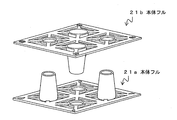
- FIG. 3 is a diagram illustrating an example of assembling the unit material.
- the unit material 2 is assembled so that the columns on the column side face each other and the columns are arranged in a staggered manner.
- the main body full 21 a has the support column facing upward
- the main body full 21 b has the support column facing downward
- the surfaces on the support column side are opposed to each other, and the two support columns are fitted in a staggered arrangement.
- FIG. 3 for the sake of clarity, only the two main body fulls 21 are assembled, but the actual assembly of the unit material will be described later with reference to FIGS. 14, 16 to 18, and FIG. 20 is performed.
- stage is used as a term indicating the height of the water tank 10.
- the example shown in FIG. 3 is “one stage”.
- the height of the water tank 10 of the rainwater storage and penetration facility 1 shown in FIG. 1 is “three steps”.
- the unit material 2 with the surface on the support column facing upward is referred to as “lower part” of each step
- the unit material 2 with the surface of the support column facing downward is referred to as “upper part”.
- the main body full 21 a is the “lower part” of each stage
- the main body full 21 b is the “upper part” of each stage.
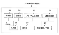
- FIG. 4 is a hardware configuration diagram of the layout design apparatus 30. Note that the hardware configuration in FIG. 1 is an example, and various configurations can be adopted depending on applications and purposes.
- the layout design apparatus 30 includes a control unit 31, a storage unit 32, a media input / output unit 33, a communication control unit 34, an input unit 35, a display unit 36, a peripheral device I / F unit 37, and the like connected via a bus 38.
- the layout design apparatus 30 includes a control unit 31, a storage unit 32, a media input / output unit 33, a communication control unit 34, an input unit 35, a display unit 36, a peripheral device I / F unit 37, and the like connected via a bus 38.
- the control unit 31 includes a CPU (Central Processing Unit), a ROM (Read Only Memory), a RAM (Random Access Memory), and the like.
- the CPU calls a program stored in the storage unit 32, ROM, recording medium or the like to a work memory area on the RAM, executes it, drives and controls each device connected via the bus 38, and is described later by the computer. Realize processing.
- the ROM is a non-volatile memory and permanently holds a computer boot program, a program such as BIOS, data, and the like.
- the RAM is a volatile memory, and temporarily stores a program, data, and the like loaded from the storage unit 32, ROM, recording medium, and the like, and includes a work area used by the control unit 31 for performing various processes.
- the storage unit 32 is an HDD (hard disk drive), and stores a program executed by the control unit 31, data necessary for program execution, an OS (operating system), and the like. With respect to the program, a control program corresponding to an OS (operating system) and an application program for causing a computer to execute processing described later are stored. Each of these program codes is read by the control unit 31 as necessary, transferred to the RAM, read by the CPU, and executed as various means.
- the media input / output unit 33 (drive device) inputs / outputs data, for example, media such as a CD drive (-ROM, -R, -RW, etc.), DVD drive (-ROM, -R, -RW, etc.) Has input / output devices.
- the communication control unit 34 includes a communication control device, a communication port, and the like, and is a communication interface that mediates communication between the computer and the network, and performs communication control between other computers via the network.
- the network may be wired or wireless.
- the input unit 35 inputs data and includes, for example, a pointing device such as a keyboard and a mouse, and an input device such as a numeric keypad.
- An operation instruction, an operation instruction, data input, and the like can be performed on the computer via the input unit 35.
- the display unit 36 includes a display device such as a CRT monitor and a liquid crystal panel, and a logic circuit (such as a video adapter) for realizing a video function of the computer in cooperation with the display device.
- the peripheral device I / F (interface) unit 37 is a port for connecting a peripheral device to the computer, and the computer transmits / receives data to / from the peripheral device via the peripheral device I / F unit 37.
- the peripheral device I / F unit 37 is configured by USB, IEEE1394, RS-232C, or the like, and usually has a plurality of peripheral devices I / F.
- the connection form with the peripheral device may be wired or wireless.
- the bus 38 is a path that mediates transmission / reception of control signals, data signals, and the like between the devices.
- FIG. 5 is a diagram illustrating an example of basic size data.
- the basic size data 40 is used when calculating the height, plane area, volume, etc. of the aquarium 10, or when creating a CAD drawing.
- the basic size data 40 includes, for example, a unit area 41, a step height 42, and the like.
- the unit area 41 is an area of the unit area, for example, “Amm ⁇ Amm”.
- the step height 42 is a height per step and is, for example, “Hmm”.
- Amm is 721 mm and Hmm is 391 mm.
- FIG. 6 is a diagram illustrating an example of the component data.
- the component data 50 is used when calculating the layout of the components of the rainwater storage and penetration facility 1, when creating a CAD drawing, when calculating the member cost of the water storage and penetration facility 1, and the like.
- the component data 50 includes, for example, a component type 51, a layout size 52, a unit price 53, and the like.
- the component data 50 with the component type 51 of “main body full” has a layout size “bottom area: Amm ⁇ Amm ⁇ 1 ⁇ height: Hmm” and a unit price 53 of “M1 yen”. It is.
- the basic size data 40 and the component element data 50 may be stored in the storage unit 32 in advance, or input through the media input / output unit 33, the communication control unit 34, the input unit 35, and the like. There may be.
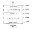
- FIG. 7 is a flowchart showing a process flow of the layout design method.
- the layout design apparatus 30 first creates a basic shape of the rainwater storage and penetration facility 1 (step S101). The processing in step S101 will be described with reference to FIGS.
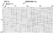
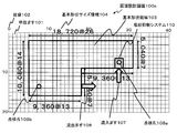
- FIG. 8 is a diagram showing an initial display example of the drawing design screen.
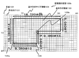
- FIG. 9 is a diagram illustrating an example of a drawing design screen after creating a basic shape.
- the control unit 31 of the layout design apparatus 30 displays a drawing design screen 100a shown in FIG. 8 on the display unit 36 according to the facility area of the facility site.
- a plurality of units 101 are shown by drawing straight lines in a lattice shape, and a scale 102 is attached.
- the reference numeral “100” is used to collectively refer to the drawing design screens.
- the user inputs the basic shape of the rainwater storage and penetration facility 1 using the input unit 35 (for example, a mouse) on the drawing design screen 100a shown in FIG.
- the control unit 31 of the layout design apparatus 30 displays the basic shape region 103 on the display unit 36 in the drawing design screen 100 b shown in FIG. 9 according to the input from the input unit 35.
- the basic shape region 103 is a closed region that is divided by a plurality of line segments with the unit 101 as a minimum unit.
- Basic shape size information 104 is displayed around the basic shape region 103.
- the basic shape size information 104 displays “actual length length @ number of units 101” corresponding to the length of each line segment.
- the partial area of the basic shape area 103 will be divided into three parts: a corner, an end, and an interior. Further, the corners are considered separately as a corner portion having an inner angle of 90 degrees and a corner portion having an inner angle of 270 degrees.
- 105a and 105b are corners, and 106 is an end. The inside is a region excluding corners and ends.
- 105a is a corner having an inner angle of 90 degrees
- 105b is a corner having an inner angle of 270 degrees.
- step S102 the layout design device 30 arranges the constituent elements excluding the unit material.
- the process of step S102 will be described with reference to FIGS.
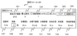
- FIG. 10 is a diagram illustrating an example of a setting form.
- the setting form 120 is displayed on the display unit 36 as another window screen together with the drawing design screen 100a of FIG.
- the setting form 120 has a unit number 121, an inspection hole 122, a sediment control system 123, an eraser 124, a clear button 125, a drawing creation button 126, a void ratio 127, a number of steps 128, a tank height 129, a water tank flat area 130, a water tank.
- Screen items such as a volume 131, an effective water depth 132, a margin height 133, and an effective storage amount 134 are included.
- the unit number 121 is a display item.
- the inspection hole 122 and the sediment control system 123 are radio buttons and display items.
- the number of inspection holes and the sediment control system arranged on the drawing design screen 100 is displayed.
- the number of units 101 is “273” (corresponding to the example shown in FIG. 9)
- the number of inspection holes is “2 (corresponding to the example shown in FIG. 12 described later)
- the number is “1” (corresponding to an example shown in FIG. 12 described later).
- the eraser 124 is a radio button.
- the radio button of the inspection hole 122, the sediment control system 123, and the eraser 124 is a set, and any one can be selected.
- the inspection hole can be arranged on the drawing design screen 100
- the radio button of the eraser 124 is selected, the components arranged on the drawing design screen 100 Can be erased.
- the clear button 125 is a button for instructing deletion of setting information. When the clear button 125 is pressed, all the components arranged on the drawing design screen 100, information set on the setting form 120, a drawing creation setting form 140 described later, and the like are all deleted.
- the drawing creation button 126 is a button for instructing display of a drawing creation setting form 140 described later.
- the porosity 127 is a display item. In the display item of the porosity 127, the porosity of the rainwater storage and penetration facility 1 under design is displayed.
- the number of stages 128 is an input item. In the input item of 128 steps, the input of the number of steps of the rainwater storage and penetration facility 1 under design is accepted.
- items such as the tank height 129 to the effective storage amount 134 are recalculated.
- the water tank height 129, the water tank flat area 130, the water tank volume 131, the effective water depth 132, the margin height 133, and the effective storage amount 134 are display items.
- Each display item includes the height, flat area, and volume of the tank of the rainwater storage and penetration facility 1 under design.
- the effective water depth, margin, and effective storage amount are displayed.
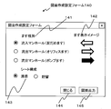
- FIG. 11 is a diagram illustrating an example of a drawing creation setting form.
- the drawing creation button 126 of the setting form 120 is pressed, the drawing creation setting form 140 is displayed on the display unit 36 as another window screen.
- the drawing creation setting form 140 includes screen items such as a type 141, a display image 142, a sheet configuration 143, a close button 144, and a drawing output 145.
- the first type 141 is a radio button.
- the type 141 is “inflow manhole (mud)”, “outflow manhole (orifice)”, “outflow manhole (pump)”, and one of them can be selected. .
- the display image 142 is a display item.
- an object (an arrow figure) arranged on the drawing design screen 100 is displayed in association with the type 141.
- the sheet configuration 143 is a radio button.
- the sheet configuration 143 includes “penetration” and “storage” as a set, and any one of them can be selected. For example, when the “osmosis” radio button is selected, a drawing of an infiltration-type rainwater storage and infiltration facility is created.
- the close button 144 is a button for instructing to close the drawing creation setting form 140.
- the drawing output button 145 is a button for instructing output of a CAD drawing.
- the layout calculation processing of the constituent elements is performed based on the constituent elements arranged on the drawing design screen 100, information set in the setting form 120, the drawing creation setting form 140 described later, and the like.
- CAD drawing creation processing is started.
- FIG. 12 is a diagram illustrating an example of a drawing design screen after component elements are arranged.
- the user uses the input unit 35 (for example, a mouse) on the drawing creation setting form 140 to select a radio button of “inflow manhole (mud)”, and the basic shape area 103 of the drawing design screen 100.
- One unit 101 is designated around (a region outside, for example, one unit separated from the basic shape region 103).
- the control unit 31 of the layout design apparatus 30 arranges the inflow into the designated unit cell 101.
- One inflow 107 is arranged on the drawing design screen 100c shown in FIG.
- the control unit 31 of the layout design device 30 arranges the outflow by the same procedure.
- One outflow 108 is arranged on the drawing design screen 100c.
- the user selects a radio button of the inspection hole 122 using the input unit 35 (for example, a mouse) on the setting form 120 and selects any one of the basic shape areas 103 included in the drawing design screen 100. Specify the unit 101.
- the control unit 31 of the layout design apparatus 30 arranges the inspection hole in the designated unit box 101.
- two inspection holes 109a and 109b are arranged.
- the control unit 31 of the layout design apparatus 30 arranges the sediment control system.
- One sediment control system 110 is arranged on the drawing design screen 100c.
- the control unit 31 of the layout design apparatus 30 determines whether or not the instruction from the input unit 35 by the user satisfies a predetermined constraint condition regarding the arrangement of the component when arranging the component. When the instruction from the user satisfies the constraint condition, the control unit 31 arranges the component according to the instruction. When the instruction does not satisfy the constraint condition, the control unit 31 does not arrange the component and displays an error message or the like as necessary. As a result, it is possible to avoid designing a layout that cannot be constructed.
- the following conditions may be given as constraints on the arrangement of the components.
- a basic shape outline is provided at a position separated by at least two full main bodies.
- the sediment control system 122 can be disposed only at a position corresponding to the inflow 107.
- Arrangement is made so as to satisfy the restriction conditions of arrangement of unit materials for the staggered arrangement (for example, restriction conditions when the main body full, the main body half, and the main body quarter are arranged in a planar layout). Specific conditions will be described later.
- the minimum necessary number of outflows 108 may be set according to the size and the number of steps of the basic shape region 103. This is because the flow rate that can flow from the outflow 108 needs to be increased in accordance with the volume of the basic shape region 103. Further, the minimum number of inspection holes 122 may be set according to the size and the number of steps of the basic shape region 103. This is because it is necessary to increase the number of inspection points and cleaning points according to the volume of the basic shape region 103.
- step S103 the layout design device 30 inputs the setting information of the rainwater storage and penetration facility 1 (step S103). The process of step S103 will be described with reference to FIGS.
- the user inputs a desired number of steps to the input item of the number of steps 128 on the setting form 120, and selects a desired sheet configuration from the radio buttons of the sheet configuration 143 on the drawing creation setting form 140.
- it may be input as setting information for other components. Examples of setting information for other components include the diameter of pipe pipes that flow in and out, foundation settings (distribution of sand, crushed stones, completes, etc.), and earth covering settings (distance from the ground 12 to the aquarium 10). And so on.
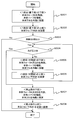
- FIG. 13 is a flowchart showing the first layout calculation processing.
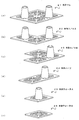
- FIG. 14 is a diagram for explaining the assembly procedure of the first stage when the corner is an internal angle of 90 degrees.
- FIG. 15 is a diagram illustrating an example of layout result data.
- FIG. 16 is a diagram for explaining a second-stage assembly procedure when the corner has an inner angle of 90 degrees.
- the control unit 31 of the layout design apparatus 30 installs the main body quarter B at the corner, the main body half at the end, and the main body full at the inside in the ⁇ first (lowermost) lower part>. (Step S201). In particular, in the ⁇ lower part of the first stage (bottom stage)>, “no main body full projection” is installed inside. Next, in the ⁇ first stage (uppermost stage)>, the control unit 31 installs the main body full downward with respect to all the units (step S202).
- FIG. 14 (a) shows that the main body quarter B26a is installed at the corner.
- FIG. 14B shows that the body halves 24a to 24d are installed at the ends.
- a gap is provided between the constituent elements so that the separation of the constituent elements is easy to understand.
- the main body quarter B 26a and the main body half 24a, the main body quarter B 26a and the main body half are illustrated.
- 24b, the main body half 24a and the main body half 24c, and the main body half 24b and the main body half 24d are installed without any gaps.
- FIG. 14B a gap is provided between the constituent elements.
- FIG. 14C shows that the main body full 21c to 21f are installed inside.
- FIG. 14D shows that the main body full 21g to 21j are installed downward with respect to all the units.
- the control unit 31 determines the positions of the main body full 21g to 21j so that the columns are arranged in a staggered manner.
- the control unit 31 stores in the storage unit 32 the layout result of the unit material 2 installed in step S201, step S202, etc. (the same applies to other steps).
- the layout result of the unit material 2 installed as shown in FIG. 14 is shown as layout result data 60.
- the layout result data 60 includes a component ID 61, a component type 62, a column number 63, a first coordinate 64, a second coordinate 65, a third coordinate 66, and the like.
- the component ID 61 is a number that uniquely identifies the component.
- the component type 62 is information that can specify the type of the unit material 2 in addition to the type of the component.
- the stage number 63 is information that can specify either the upper part or the lower part of each stage in addition to the stage number.
- the first coordinate 64, the second coordinate 65, and the third coordinate 66 are information that can specify the horizontal position of the component (the position in the two-dimensional coordinate). For example, if the first coordinate 64 is the upper left coordinate of the component, the second coordinate 65 is the lower left coordinate of the component, and the third coordinate 66 is the upper right coordinate of the component, the horizontal position of the component is specified.
- the layout result data 60 shown in FIG. 15 is an example, and the present invention is not limited to this example. The way of holding data can be changed as appropriate.
- control unit 31 determines whether or not the “number of stages” input in step S103 is two or more (step S203). In the case of one stage (No in Step S203), the control unit 31 ends the process. If there are two or more stages (Yes in step S203), the control unit 31 proceeds to step S204.
- control unit 31 determines whether or not the next stage to be processed is the uppermost stage (step S204). If it is not the uppermost stage (No in step S204), the control unit 31 proceeds to step S205. In the case of the uppermost stage (Yes in step S204), the control unit 31 proceeds to step S207.
- step S205 the control unit 31 sets the main body quarter A or B to the corner, the main body half to the end, and the main body full to the inside in the ⁇ lower part of the i-th stage (intermediate stage)> (i is a natural number of 2 or more). Install. In particular, the main body quarter B is installed in the odd-numbered stages, and the main body quarter A is installed in the even-numbered stages.
- the control unit 31 installs the main body full downward with respect to all the units in the ⁇ i-th stage (intermediate stage)>, and returns to step S204 (step S206).
- FIG. 16A shows that the main body quarter A25a is installed at the corner.
- FIG. 16B shows that the main body halves 24e to 24h are installed at the ends.
- FIG. 16C shows that the main body full 21k to 21n is installed inside.
- FIG. 16 (d) shows that the main body full 21o to 21r are installed downward with respect to all units.
- the control unit 31 determines the positions of the main body full 21o to 21r so that the support columns are arranged in a staggered manner.
- step S207 the control unit 31 installs the main body quarter A or B in the corner, the main body half in the end, and the main body full in the inner part in the ⁇ lowermost part>.
- the main body quarter B is installed in the odd-numbered stage
- the main body quarter A is installed in the even-numbered stage.
- the control unit 31 installs the main body full downward with respect to all the units in ⁇ uppermost upper part>, and ends the process (step S208). In particular, install “Without full body protrusions” at the top of the top.
- the layout design device 30 performs the layout calculation of the unit material 2 as described above.
- FIG. 17 is a diagram for explaining the assembly procedure of the first stage in the case where the corner has an inner angle of 270 degrees.
- FIG. 18 is a diagram for explaining a second-stage assembly procedure when the corner portion has an inner angle of 270 degrees.
- the basic processing flow is the same as (1) the assembly procedure when the corner has an inner angle of 90 degrees, and the processing is performed according to the flowchart shown in FIG. However, compared with the case of (1), the number of body quarters A25 or body quarters B26 arranged at the corners is different.
- FIG. 17A one main body quarter B26b and two main body quarters A25b and 25c are installed at the lower corner.
- FIG. 17B main body halves 24i and 24j are installed at the lower end.
- FIG. 17 (c) the main body full 21s to 21w are installed inside the lower part.
- FIG. 17 (d) the main body full 21x to 21ae are installed downward in all the upper units.
- FIG. 18A one main body quarter A25d and two main body quarters B25c, 25d are installed at the lower corner.
- FIG. 18B main body halves 24k and 24l are installed at the lower end.
- FIG. 18C the main body full 21af to 21aj are installed inside the lower part.
- FIG. 18 (d) the main body fulls 21ak to 21ar are installed downward in all the upper units.
- the layout design device 30 performs the layout calculation of the unit material 2 as described above.
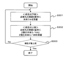
- the control unit 31 of the layout design apparatus 30 installs eight main bodies full at eight locations around the inspection hole in the ⁇ i-th lower part> (i is a natural number) (step S301).
- the control unit 31 installs the two main bodies 3 / 4A and the two main bodies 3 / 4B at four locations around the inspection hole in the ⁇ i-stage upper portion> (step S302).
- the control unit 31 determines whether or not the current stage is the highest level (step S303). If the current level is not the highest level (No in step S303), the control unit 31 repeats the process from S301, and if it is the highest level (Yes in step S303), performs the process. finish.
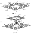
- FIG. 20A shows that the main body full 21ba to 21bh are installed at eight places around the inspection hole 7 in the upper part of each stage.
- FIG. 20B shows that the main bodies 3 / 4A 22a and 22b and the main bodies 3 / 4B 23a and 23b are installed at four locations around the inspection hole 7 in the lower part of each stage.
- the layout design device 30 performs the layout calculation of the unit material 2 as described above.
- the above-described (1) assembly procedure when the corner is an inner angle of 90 degrees, (2) assembly procedure when the corner is an inner angle of 270 degrees, and (3) the assembly procedure around the inspection hole are consistent with each other.
- the layout design device 30 calculates the layout of the unit material 2 in accordance with each assembly procedure according to the size of the inner corner of the corner and the presence or absence of the inspection hole.
- control unit 31 of the layout design apparatus 30 creates a CAD drawing based on the layout calculation result in step S104, and outputs a CAD file (step S105).
- the control unit 31 outputs the layout calculation result in step S104 to a temporary file.
- the control unit 31 outputs data indicating the position of each component (for example, layout result data 60 shown in FIG. 15), data indicating the number of each component type, and the like to a temporary file. All members necessary for the construction of the rainwater storage and penetration facility 1 are picked up in the temporary file.
- the control unit 31 converts the data of the temporary file into a CAD file (for example, a dxf file) by a known technique.
- the CAD file includes the layout of the unit material 2 at each stage.
- the layout of the unit material 2 at each stage can be used as information for construction management and progress management when actually performing construction.
- the control part 31 calculates the member cost required for construction of the rainwater storage penetration facility 1 using the data (for example, component data 50 shown in FIG. 6) which shows the unit price of a component, for example.
- FIG. 21 is a diagram illustrating an example of a CAD drawing output by the layout design apparatus 30.
- the layout design apparatus 30 of the present invention if used, it becomes possible to design a layout required at the time of construction by a simple operation. That is, according to the present invention, even a person who has no knowledge of the rainwater storage and penetration facility can design the layout of the rainwater storage and penetration facility in a short time.
- the layout calculation of the unit material fitted by the staggered arrangement is performed.
- the layout design apparatus 30 of the present invention can also perform the layout calculation of other unit materials.
- the present invention can also be applied to a case where the upper unit material and the lower unit material of each stage face each other one to one.
- the layout design apparatus 30 simply arranges unit materials having the same area as the unit, one unit at a time.
- the joint which connects unit materials is needed.
- Such an arrangement is called a counter arrangement.
- the opposed arrangement is rarely used due to problems of earth pressure and shear stress.
- an opposing arrangement may be used.
- the rainwater storage and penetration facility 1 can be formed only with the unit material of the main body full 21.
- the unit material of the lower main body full 21 and the upper unit material of the main body full 21 can be arranged so as to face each other.
- a unit material other than the main body full 21 may be used, for example, the main body half 24 is arranged only on one side.
- Modification 1 of the embodiment of the present invention will be described with reference to FIG.
- the layout design of the rainwater storage and penetration facility 1 in order to ensure the strength of the rainwater storage and penetration facility 1 against horizontal shear stress caused by loads such as earth pressure, the body full 21, the body half 24, and the body quarter A25 And the structure of the staggered arrangement is constructed by combining the main body quarter B26.
- various plane layouts of the basic shape region 103 can be considered.
- the layout design apparatus 30 outputs a plurality of planar layouts of the basic shape region 103 that can be constructed by adding the site shape and the predetermined capacity to the constraint conditions.
- the output data includes the required number for each constituent element.
- the number of sediment control systems 8 and the number of inspection holes 7 shown in FIG. 1 and the position of the inflow pipe 15 are input in advance.
- FIG. 22 is a diagram illustrating an example of a planar layout design.
- the layout design device 30 according to the first modification designs the planar layout 71 so as to satisfy the following constraint conditions.
- the sediment control system 8 is disposed at a position corresponding to the inflow pipe 15.
- the plane layout 71 (basic shape region 103) is arranged inside the site shape 70.
- the plane layout 71 is designed so that the water tank 10 has a predetermined capacity.
- the main body quarter A25 or the main body quarter B26 is arranged at the corner of the planar layout 71 (basic shape region 103).
- the main body half 24 is disposed at the end of the planar layout 71 (basic shape region 103).
- the main body full 21 is arranged inside the planar layout 71 (basic shape region
- the site shape 70 is rectangular as shown in FIG.
- the predetermined capacity of the water tank 10 is set to a constant depth
- the plane layout 71 for 3600 pieces of the main body half 24 is, for example, 1 vertical x 3600 horizontal, 2 vertical x 1800 horizontal, ..., 40 vertical x 90 horizontal, ..., 60 vertical.
- the layout design apparatus 30 outputs a plurality of planar layouts that satisfy all of the above-mentioned constraints.
- those satisfying all of the above-mentioned constraints are the 60 vertical ⁇ 60 horizontal planar layouts 71a shown in FIG. 22A and the 40 vertical ⁇ 90 horizontal layouts shown in FIG. 22B. 71b.
- the required number of main body halves 24 is different.
- the member cost required for the construction of the rainwater storage and penetration facility 1 is also different. For example, when the main body half 24 is higher than the main body full 21, the planar layout 71 a with fewer main body halves 24 can reduce the total member cost.
- the site shape 70 is rectangular, but the present invention is not limited to this example, and can also be applied to an L-shaped site shape 70.
- the plurality of planar layouts 71 and the necessary number of components that satisfy the constraint conditions are output.
- the present invention is not limited to this example.
- the member cost calculation may be performed for each of the plurality of planar layouts 71, and the plurality of planar layouts 71 may be output in order from the lowest member cost, or only the planar layout 71 having the lowest member cost may be output. .
- the constraint condition may include the following.
- the distance from the boundary of the site shape 70 to the boundary of the planar layout 71 is at least a predetermined distance (for example, 2 to 3 m). ⁇ If there are banks or buildings adjacent to the site, the earth pressure will increase due to them, so the distance from the boundary of the site shape 70 to the boundary of the plane layout 71 The distance is taken into consideration.
- ⁇ Modification 2> a second modification of the embodiment of the present invention will be described with reference to FIGS.
- ⁇ Soil cover Vertical dead load. Check against vertical long-term load.
- Water tank bottom depth horizontal earth pressure. Check against horizontal and long-term loads.
- Vehicle load standard at the top of the tank Live load in the vertical direction. Check for vertical short-term loads.
- the layout design device 30 is input with conditions such as “soil covering”, “aquarium bottom depth”, “aquarium shape (plane size)”, “vehicle load standard at the top of the aquarium”, and the like. And the load added to the water tank 10 is calculated, the component (especially unit material) which can ensure predetermined intensity
- the component especially unit material which can ensure predetermined intensity
- there are a plurality of types of unit materials such as the main body full 21, the main body half 24, the main body quarter A25, and the main body quarter B26 that have different horizontal strength and vertical strength. Note that designing the planar layout so as to satisfy the constraint conditions is the same as in the first modification.
- FIG. 23 is a diagram showing an example of the component data.
- the component data 80 includes, for example, a component type 81, an intensity classification 82, an intensity 83, a unit price 84, and the like.
- the strength class 82 is an item for distinguishing among the unit materials having the same component type 81 that have different horizontal strength and / or vertical strength. For example, a unit material whose component type 81 is “main body full” and strength classification 82 is “A” has a strength 83 of “horizontal load resistance ⁇ (kN / m2), vertical load resistance ⁇ (kN / m2)”. "The unit price 84 is" M21 yen ".
- a unit material whose component type 81 is “main body full” and strength classification 82 is “B” has a strength 83 of “horizontal load resistance ⁇ + ⁇ (kN / m 2), vertical load resistance ⁇ (kN / m2) ”and the unit price 84 is“ M22 yen ”.
- a unit material whose component type 81 is “main body full” and strength classification 82 is “C” has a strength 83 of “horizontal load resistance ⁇ (kN / m 2), vertical load resistance ⁇ + ⁇ (kN / m2) ”and the unit price 84 is“ M23 yen ”.
- FIG. 24 is a diagram illustrating an example of a horizontal load.
- the number of unit materials is reduced for easy understanding.
- the layout design device 30 calculates, for example, the horizontal load 74 applied to the water tank 10 generated by the building for each unit 101 of the planar layout. Then, the layout design apparatus 30 refers to the component data 80, and selects a unit material that can withstand the calculated horizontal load 74 that minimizes the member cost.
- the layout design device 30 is the unit material with the lowest unit price 84 among the unit materials whose horizontal load resistance value set as the strength 83 of the component element data 80 is larger than the horizontal load 74. Is selected.
- the calculation process of the horizontal direction load 74 is a well-known technique, description is abbreviate
- the layout design device 30 selects the unit material of the reinforcing region 76a that has the strength classification 82 of “B”. As for the unit material other than the reinforcing region 76a, one having the strength classification 82 of “A” is selected.
- FIG. 25 is a diagram illustrating an example of a vertical load. In the example shown in FIG. 25 as well, the number of unit materials is reduced for easy understanding of the description.
- the ground 12 of the site where the rainwater storage and penetration facility 1 is constructed has a slope.
- the vertical load 75 of the earth covering is applied to the water tank 10 according to the distance from the upper part of the water tank 10 to the ground surface of the ground 12. Therefore, the layout designing apparatus 30 calculates the vertical load 75 of the earth covering for every unit 101 of the planar layout, for example.
- the layout design device 30 refers to the component data 80, and selects a unit material that can withstand the calculated vertical load 75 that minimizes the member cost.
- the layout design device 30 is the unit material having the lowest unit price 84 among the unit materials having a vertical load capacity value set as the strength 83 of the component data 80 larger than the vertical load 75. Is selected.
- the calculation process of the vertical direction load 75 is a well-known technique, description is abbreviate
- the layout design device 30 selects the unit material of the reinforcing region 76b having the strength classification 82 of “C”. For the unit material other than the reinforcing region 76b, the material having the strength classification 82 of “A” is selected.
- the layout design device 30 calculates the horizontal load 74 and / or the vertical load 75 applied to the water tank 10 and selects a unit material that can ensure a predetermined strength. It is not limited to examples.
- the layout design apparatus 30 may fix the strength classification 82 of the unit material used for construction and determine whether or not a predetermined strength can be secured for the site environment scheduled for construction.
- Modification 3 of the embodiment of the present invention will be described.
- the on-site conditions include a material storage space, a truck transport route, a road width, usable heavy equipment (such as a unic car or a rough terrain crane), a drilling hole shape, a water tank shape (planar shape ⁇ height), and the like. Therefore, in the third modification, the layout design device 30 calculates the work artificial number necessary for excavation and the work artificial number necessary for assembly when the above-mentioned site conditions are input, and further calculates the tank assembly work period. ,Output.
- the number of times of transportation of parts necessary for construction, the transportation route, the transportation distance, the size of the truck used for transportation, and the like from the space for the material storage, the truck transportation route, the usable road width, and the like.
- the size of heavy equipment that can be used is determined from the road width, the shape of the drilling hole, the shape of the water tank (planar shape x height), etc. It is possible to calculate the number of work man-hours and the number of work man-days required for assembly, and finally obtain the tank assembly work period by calculation. In this way, not only the construction cost but also the transportation cost and the water tank assembly work period can be obtained, which can be used for construction progress management.
- Modification 4 of the embodiment of the present invention will be described.
- the layout design device 30 calculates the type and quantity of spare parts to be delivered to the site when the planar layout design is completed and the necessary number of each component and the tank assembly work period are determined. And output.
- the number of spare members currently carried in is set in advance. For example, if the number of members to be used exceeds several hundred, the full-sized main unit is 1% of the total amount used. % Can be determined as appropriate by preparing 2% for the half-sized main body half unit material with a small amount of use, and preparing 2-3 unit materials for the quarter-sized main body quarter with a smaller amount of use. Thereby, even if the unit member under construction is damaged, the construction can proceed without delay. It is possible to eliminate the waste of labor costs due to the interruption of construction due to waiting for members, to reduce construction costs, and to prevent delays in construction progress.
Landscapes
- Engineering & Computer Science (AREA)
- Architecture (AREA)
- Health & Medical Sciences (AREA)
- Life Sciences & Earth Sciences (AREA)
- Hydrology & Water Resources (AREA)
- Public Health (AREA)
- Water Supply & Treatment (AREA)
- General Engineering & Computer Science (AREA)
- Civil Engineering (AREA)
- Structural Engineering (AREA)
- Sewage (AREA)
Abstract
Description
最初に、図1から図3を参照しながら、本発明の実施形態に係る雨水貯留浸透施設の概要について説明する。
被覆層4は、水槽10の全面(上面、底面、側面)を覆う為のシートである。被覆層4には、遮水シート、透水シート、保護シート等がある。遮水シートは、雨水を貯留するために水槽10の外面と周辺地盤との間に敷設するシートである。透水シートは、水槽10と浸透層を隔てる透水性を有したシートである。保護シートは、ユニット材2や埋戻土による遮水シートの破損を防止するシートである。
流出ます6は、雨水を水槽10から流出させる為の構成部材である。流出ます6には、「オリフィスます」、「ポンプます」等がある。「オリフィスます」は、オリフィスを用いて雨水の流出量を調整する。「ポンプます」は、ポンプを用いて雨水の流出量を調整する。
ここで、雨水貯留浸透施設1の基本形状は、正方形のますを最小単位とし(以下、「単位ます」という。)、単位ますを複数並べることによって作成されるものである。
図3に示す例では、本体フル21aが支柱を上向き、本体フル21bが支柱を下向きとし、互いに支柱側の面を対向させ、それぞれ2本の支柱が千鳥配置となるように嵌合される。
尚、図3に示す例は、分かり易くする為に、2個の本体フル21だけの組立となっているが、実際のユニット材の組立は、後述する図14、図16~図18、図20のように行われる。
また、以下では、支柱側の面が上向きのユニット材2を各段の「下部」といい、支柱側の面が下向きのユニット材2を各段の「上部」という。例えば、図3に示す例では、本体フル21aが各段の「下部」であり、本体フル21bが各段の「上部」である。
基本サイズデータ40は、例えば、単位ます面積41、段高さ42などを含む。単位ます面積41は、単位ますの面積であり、例えば、「Amm×Amm」である。段高さ42は、1段当たりの高さであり、例えば、「Hmm」である。具体的な数値の一例としては、Ammは721mmであり、Hmmは391mmである。
構成要素データ50は、例えば、構成要素の種類51、レイアウト上のサイズ52、単価53などを含む。例えば、構成要素の種類51が「本体フル」の構成要素データ50は、レイアウト上のサイズが「底面積:Amm×Amm×1倍、高さ:Hmm」であり、単価53が「M1円」である。
基本サイズデータ40や構成要素データ50は、予め記憶部32に記憶されるものであっても良いし、メディア入出力部33、通信制御部34、入力部35等を介して入力されるものであっても良い。
レイアウト設計装置30の制御部31は、施設現場の施設領域に応じて、図8に示す図面設計画面100aを表示部36に表示する。図8には、格子状に直線が引かれることによって、複数の単位ます101の領域が示され、目盛102が付けられている。
以下では、図面設計画面を総称するときは符号「100」を付すことにする。
レイアウト設計装置30の制御部31は、入力部35からの入力に従い、図9に示す図面設計画面100bにおいて、基本形状領域103を表示部36に表示する。基本形状領域103は、単位ます101を最小単位とし、複数の線分によって区切られる閉領域である。基本形状領域103の周囲には、基本形状サイズ情報104が表示される。基本形状サイズ情報104は、各線分の長さに対応して、「実寸の長さ@単位ます101の個数」が表示される。図9に示す基本形状領域103は、「18,720@26」、「5,040@7」、「9,360@13」、「5,040@7」、「9,360@13」、「10,080@14」の6本の線分によって囲まれた閉領域である。ここで、最小単位としては、単位ますの長さの1/2倍、1倍、2倍等が使用できる。
設定フォーム120は、図8の図面設計画面100aと合わせて、別のウィンドウ画面として表示部36に表示される。
設定フォーム120は、単位ます個数121、点検孔122、堆砂抑制システム123、消しゴム124、クリアボタン125、図面作成ボタン126、空隙率127、段数128、水槽高さ129、水槽平面積130、水槽容積131、有効水深132、余裕高133、有効貯留量134などの画面項目を含む。
点検孔122、堆砂抑制システム123は、ラジオボタン及び表示項目である。点検孔122、堆砂抑制システム123の表示項目には、図面設計画面100において配置される点検孔、堆砂抑制システムの個数が表示される。図10に示す例では、単位ます101の個数は「273」(図9に示す例に対応)、点検孔の個数は「2(後述する図12に示す例に対応)、堆砂抑制システムの個数は「1」(後述する図12に示す例に対応)である。
消しゴム124は、ラジオボタンである。
点検孔122、堆砂抑制システム123及び消しゴム124のラジオボタンが一組となっており、いずれか一つが選択可能になっている。例えば、点検孔122のラジオボタンが選択されると、図面設計画面100に点検孔が配置可能な状態となり、消しゴム124のラジオボタンが選択されると、図面設計画面100に配置されている構成要素を消去可能な状態となる。
図面作成ボタン126は、後述する図面作成設定フォーム140の表示を指示する為のボタンである。
段数128は、入力項目である。段数128の入力項目では、設計中の雨水貯留浸透施設1の段数の入力を受け付ける。段数128の入力項目に数字が入力されると、水槽高さ129~有効貯留量134などの項目が再計算される。
水槽高さ129、水槽平面積130、水槽容積131、有効水深132、余裕高133、有効貯留量134は、表示項目である。それぞれの表示項目には、設計中の雨水貯留浸透施設1の水槽の高さ、平面積、容積。有効水深、余裕高、有効貯留量が表示される。
図面作成設定フォーム140は、設定フォーム120の図面作成ボタン126が押下されると、別のウィンドウ画面として表示部36に表示される。図面作成設定フォーム140は、ます種別141、ます表示イメージ142、シート構成143、閉じるボタン144、図面出力145などの画面項目を含む。
ます表示イメージ142は、表示項目である。ます表示イメージ142には、ます種別141に対応させて、図面設計画面100に配置されるオブジェクト(矢印の図形)が表示される。
シート構成143は、ラジオボタンである。シート構成143は、「浸透」、「貯留」が一組となっており、いずれか一つが選択可能になっている。例えば、「浸透」のラジオボタンが選択されると、浸透型の雨水貯留浸透施設の図面が作成される。
図面出力ボタン145は、CAD図面の出力を指示する為のボタンである。図面出力ボタン145が押下されると、図面設計画面100において配置されている構成要素、設定フォーム120や後述する図面作成設定フォーム140等において設定されている情報に基づいて、構成要素のレイアウト算出処理(図7のステップS104)、CAD図面の作成処理(図7のステップS105)が開始される。
ユーザは、例えば、図面作成設定フォーム140において、入力部35(例えば、マウスなど)を用いて、「流入マンホール(泥だめます)」のラジオボタンを選択し、図面設計画面100の基本形状領域103の周囲(外側の領域であって、例えば、基本形状領域103から1個の単位ます分離れた位置)のいずれかの単位ます101を指定する。これに応じて、レイアウト設計装置30の制御部31は、指定された単位ます101に、流入ますを配置する。図12に示す図面設計画面100cには、1個の流入ます107が配置されている。同様の手順により、レイアウト設計装置30の制御部31は、流出ますを配置する。図面設計画面100cには、1個の流出ます108が配置されている。
(1)敷地隣地境界線から基本形状の輪郭をなす線までの距離として、例えば、最低本体フル2個分以上離れた位置に基本形状の輪郭線を設ける。点検孔122は、基本形状領域103の境界からT(例えば、T=1、1.5、又は2)個の単位ます分以上離れた位置にしか配置できない。ここで、Tは、深さに応じて土圧を計算することにより、最適な値が決定される。例えば、雨水貯留浸透施設1の深さが4.5mまでなら、T=1.5とする。
(2)堆砂抑制システム122は、流入ます107と対応する位置にしか配置できない。
(3)千鳥配列とするためのユニット材の配列の制約条件(たとえば、本体フル、本体ハーフ、本体クォータを平面レイアウトに配置する場合の制約条件)を満たすように配置する。具体的な条件は後述する。
その他の制約条件として、例えば、基本形状領域103の大きさ及び段数に応じて、必要最低限の流出ます108の個数などを設定しても良い。これは、基本形状領域103の容積に応じて、流出ます108から流すことができる流量を大きくしておく必要があるからである。また、基本形状領域103の大きさ及び段数に応じて、必要最低限の点検孔122の個数などを設定しても良い。これは、基本形状領域103の容積に応じて、点検箇所や清掃箇所を増やす必要があるからである。
その他、必要に応じて、その他の構成要素の設定情報として入力可能にしても良い。その他の構成要素の設定情報としては、例えば、流入ますや流出ますのパイプ管の径、基礎の設定(砂、砕石、コンプリートなどの配分)、土被り設定(地面12から水槽10までの距離)などが考えられる。
(1)角部が内角90度の場合の組立手順
(2)角部が内角270度の場合の組立手順
(3)点検孔の周囲の組立手順
次に、制御部31は、<1段目(最下段)の上部>において、全ての単位ますに対して、本体フルを下向きに設置する(ステップS202)。
構成要素のID61は、構成要素を一意に識別する番号である。構成要素の種類62は、構成要素の種類に加えて、ユニット材2の種類まで特定可能な情報である。段番号63は、段の番号に加えて、各段の上部又は下部のいずれかまで特定可能な情報である。
第1座標64、第2座標65及び第3座標66は、構成要素の水平方向の位置(2次元座標における位置)を特定可能な情報である。例えば、第1座標64が構成要素の左上座標、第2座標65が構成要素の左下座標、第3座標66が構成要素の右上座標とすれば、構成要素の水平方向の位置が特定される。
次に、制御部31は、<i段目(中間段)の上部>において、全ての単位ますに対して、本体フルを下向きに設置し、ステップS204に戻る(ステップS206)。
次に、制御部31は、<最上段の上部>において、全ての単位ますに対して、本体フルを下向きに設置し、処理を終了する(ステップS208)。特に、<最上段の上部>には、「本体フル突起なし」を設置する。
角部が内角90度の場合、レイアウト設計装置30は、以上のように、ユニット材2のレイアウト計算を行う。
図17(a)に示すように、下部の角部に、1個の本体クォータB26b、2個の本体クォータA25b、25cが設置される。次に、図17(b)に示すように、下部の端部に、本体ハーフ24i、24jが設置される。次に、図17(c)に示すように、下部の内部に、本体フル21s~21wが設置される。次に、図17(d)に示すように、上部の全ての単位ますに、本体フル21x~21aeが下向きに設置される。
図18(a)に示すように、下部の角部に、1個の本体クォータA25d、2個の本体クォータB25c、25dが設置される。次に、図18(b)に示すように、下部の端部に、本体ハーフ24k、24lが設置される。次に、図18(c)に示すように、下部の内部に、本体フル21af~21ajが設置される。次に、図18(d)に示すように、上部の全ての単位ますに、本体フル21ak~21arが下向きに設置される。
角部が内角270度の場合、レイアウト設計装置30は、以上のように、ユニット材2のレイアウト計算を行う。
次に、制御部31は、<i段目の上部>において、点検孔の周囲4箇所に、2個の本体3/4Aと2個の本体3/4Bを設置する(ステップS302)。
次に、制御部31は、現在が最上段か否か判定し(ステップS303)、最上段でない場合(ステップS303のNo)、S301から繰り返し、最上段の場合(ステップS303のYes)、処理を終了する。
点検孔がある場合、レイアウト設計装置30は、以上のように、ユニット材2のレイアウト計算を行う。
制御部31は、公知の技術によって、一時ファイルのデータを、CADファイル(例えば、dxfファイルなど)に変換する。CADファイルには、各段のユニット材2のレイアウトが含まれる。各段のユニット材2のレイアウトは、実際に施工を行うときの施工管理、進捗管理の情報として用いることができる。
また、制御部31は、例えば、構成要素の単価を示すデータ(例えば、図6に示す構成要素データ50)を用いて、雨水貯留浸透施設1の施工に必要な部材コストの計算を行う。
前述の説明では、千鳥配置によって嵌合されるユニット材のレイアウト計算を行うものとしたが、本発明のレイアウト設計装置30は、その他のユニット材のレイアウト計算も行うことができる。例えば、各段の上部のユニット材及び下部のユニット材が1対1に上下対向するような場合にも適用可能である。この場合、レイアウト設計装置30は、単に、1個の単位ますに対して、単位ますと同じ面積を有するユニット材を1個ずつ配置していくことになる。尚、このようなユニット材の場合、ユニット材同士をつなぐ継ぎ手が必要となる。このような配置は、対向配置と呼ばれる。一般には、土圧やせん断応力の問題から、対向配置を用いることは少ない。但し、土圧が少ない環境で、底が浅い水槽10の場合、対向配置を用いることもある。対向配置の場合、本体フル21のユニット材のみで雨水貯留浸透施設1を形成することができる。対向配置の場合、図17の内容と異なり、下側の本体フル21のユニット材と本体フル21の上側のユニット材とが1対1に対向するように配置することができる。もちろん、平面レイアウトの形状によっては、例えば1辺だけに本体ハーフ24を配置するなど、本体フル21以外のユニット材を用いても良い。
次に、図22を参照しながら、本発明の実施形態の変形例1について説明する。雨水貯留浸透施設1のレイアウト設計では、土圧等の荷重によって生じる水平方向のせん断応力に対して、雨水貯留浸透施設1の強度を担保するために、本体フル21、本体ハーフ24、本体クォータA25及び本体クォータB26を組み合わせて、千鳥配置の構造体を構築する。この際、敷地形状に合わせて所定の容量の水槽10を設計するために、様々な基本形状領域103の平面レイアウトが考えられる。
・点検孔7及び堆砂抑制システム8は、平面レイアウト71(基本形状領域103)の境界からT(T=1、1.5、又は2)個の単位ます分以上離れた位置に配置する。
・堆砂抑制システム8は、流入管15と対応する位置に配置する。
・平面レイアウト71(基本形状領域103)は、敷地形状70の内部に配置する。
・平面レイアウト71は、水槽10が所定の容量となるように設計する。
・平面レイアウト71(基本形状領域103)の角部には、本体クォータA25又は本体クォータB26を配置する。
・平面レイアウト71(基本形状領域103)の端部には、本体ハーフ24を配置する。
・平面レイアウト71(基本形状領域103)の内部には、本体フル21を配置する。
・敷地形状70の境界から平面レイアウト71の境界までの距離は、少なくとも所定の距離(例えば、2~3m)以上とする。
・敷地に隣接して、土手や建築物が存在する場合には、それらによって土圧が増加することを考慮し、敷地形状70の境界から平面レイアウト71の境界までの距離は、更に土圧の影響を考慮した距離とする。
次に、図23~図25を参照しながら、本発明の実施形態の変形例2について説明する。雨水貯留浸透施設1のレイアウト設計では、雨水貯留浸透施設1の強度を担保するために、以下に例示する水槽10に加わる荷重を考慮して、千鳥配置の構造体を構築する。
・土被り:鉛直方向死荷重。鉛直方向長期荷重に対する照査。
・水槽底面深さ:水平土圧。水平方向短期荷重及び長期荷重に対する照査。
・水槽上部の車両荷重規格:鉛直方向活荷重。鉛直方向短期荷重に対する照査。
次に、本発明の実施形態の変形例3について説明する。雨水貯留浸透施設1の施工作業では、現場の条件によって作業人工数が変わる。ここで、現場の条件とは、資材置き場のスペース、トラック搬送ルート、道幅、使用可能重機(ユニック車又はラフタークレーン等)、掘削孔形状、水槽形状(平面形状×高さ)等である。そこで、変形例3では、レイアウト設計装置30は、前述の現場の条件が入力されると、掘削に必要な作業人工数や組み立てに必要な作業人工数計算しさらに、水槽組立工事期間を計算し、出力する。
次に、本発明の実施形態の変形例4について説明する。雨水貯留浸透施設1の施工作業では、予備部材を確保しておく必要がある。そこで、変形例4では、レイアウト設計装置30は、平面レイアウトの設計が終了し、構成要素ごとの必要個数や水槽組立工事期間等が決まると、現場に納入すべき予備部材の種類と数量を計算し、出力する。
2………ユニット材
3………壁材
4………被覆層
5………流入ます
6………流出ます
7………点検孔
8………堆砂抑制システム
9………パーティション
10………水槽
21………本体フル
22………本体3/4A
23………本体3/4B
24………本体ハーフ
25………本体クォータA
26………本体クォータB
30………レイアウト設計装置
101………単位ます
103………基本形状領域
Claims (8)
- コンピュータを用いて、水平方向の断面に対して所定の高さを有する雨水貯留浸透施設のレイアウトを設計するレイアウト設計方法であって、
前記雨水貯留浸透施設の水平方向の断面である基本形状を作成し、
前記雨水貯留浸透施設の設定情報を入力し、
前記基本形状の内部又は周囲に前記雨水貯留浸透施設の構成要素を配置する際、前記構成要素の配置に関する制約条件を満たすか否か判定し、前記制約条件を満たさない場合には前記構成要素を配置しないように制御し、
前記基本形状、前記設定情報及び配置済の前記構成要素に基づいて、前記雨水貯留浸透施設を構成するために千鳥配置によって嵌合されるユニット材のレイアウトを、予め定められた前記ユニット材の組立手順に従って計算するレイアウト設計方法。 - 前記制約条件は、前記雨水貯留浸透施設の点検孔及び堆砂抑制システムを前記基本形状の境界から所定の距離だけ離すこと、及び、前記堆砂抑制システムを前記雨水貯留浸透施設の流入管と対応する位置に配置すること、を含む
ことを特徴とする請求項1に記載のレイアウト設計方法。 - 前記ユニット材の種類は、前記基本形状の単位ますと同じ面積であって2本の支柱を有する本体フル、前記基本形状の単位ますの3/4の面積であって2本の支柱を有する第1の本体3/4、前記基本形状の単位ますの3/4の面積であって1本の支柱を有する第2の本体3/4、前記基本形状の単位ますの1/2の面積であって1本の支柱を有する本体ハーフ、前記基本形状の単位ますの1/4の面積であって1本の支柱を有する第1の本体クォータ、前記基本形状の単位ますの1/4の面積であって支柱がない第2の本体クォータ、を含み、
前記設定情報は、前記雨水貯留浸透施設の段数を含み、
前記雨水貯留浸透施設の各段の下部には、前記基本形状の角部に前記第1の本体クォータ又は前記第2の本体クォータ、前記基本形状の端部に前記本体ハーフ、及び、前記基本形状の内部に前記本体フルを配置し、更に、前記雨水貯留浸透施設の各段の上部には、前記本体フルを配置することを前記段数に応じて繰り返すことによって、各段の前記ユニット材のレイアウトを設計し、
前記点検孔又は前記堆砂抑制システムが配置されている場合には、前記点検孔又は前記堆砂抑制システムの周囲8箇所に8個の前記本体フルを配置し、更に、前記点検孔又は前記堆砂抑制システムの周囲4箇所に2個の前記第1の本体3/4及び2個の前記第2の本体3/4を配置することを前記段数に応じて繰り返すことによって、各段の前記点検孔又は前記堆砂抑制システムの周囲のレイアウトを設計する
ことを特徴とする請求項2に記載のレイアウト設計方法。 - 前記制約条件は、前記基本形状を前記雨水貯留浸透施設の敷地形状の内部に配置すること、及び、前記基本形状の平面レイアウトを、前記雨水貯留浸透施設の水槽が所定の容量となるようにすること、を含み、
施工可能な前記ユニット材のレイアウトを複数出力する
ことを特徴とする請求項1~請求項3のいずれかに記載のレイアウト設計方法。 - 前記構成要素の単価を示すデータを用いて、前記雨水貯留浸透施設の施工に必要な部材コストを計算し、
さらに、必要に応じて前記ユニット材のレイアウトに必要な部材コストの他、前記雨水貯留浸透施設の施工に必要な施工コストを出力する
ことを特徴とする請求項4に記載のレイアウト設計方法。 - 前記雨水貯留浸透施設の水槽に加わる荷重を計算し、
所定の強度を担保できる前記ユニット材を選定し、
選定された前記ユニット材の組合せを出力する
ことを特徴とする請求項4のいずれかに記載のレイアウト設計方法。 - 水平方向の断面に対して所定の高さを有する雨水貯留浸透施設のレイアウトを設計するレイアウト設計装置であって、
前記雨水貯留浸透施設の水平方向の断面である基本形状を作成する基本形状作成手段と、
前記雨水貯留浸透施設の設定情報を入力する設定情報入力手段と、
前記基本形状の内部又は周囲に前記雨水貯留浸透施設の構成要素を配置する際、前記構成要素の配置に関する制約条件を満たすか否か判定し、前記制約条件を満たさない場合には前記構成要素を配置しないように制御する構成要素配置制御手段と、
前記基本形状、前記設定情報及び配置済の前記構成要素に基づいて、前記雨水貯留浸透施設を構成するために千鳥配置によって嵌合されるユニット材のレイアウトを、予め定められた前記ユニット材の組立手順に従って計算するレイアウト計算手段と、
前記構成要素の単価を示すデータを用いて、前記雨水貯留浸透施設の施工に必要な部材コストと施工コストの少なくともいずれかを計算するコスト計算手段と、
前記ユニット材のレイアウト、及び前記雨水貯留浸透施設の施工に必要な部材コストと施工コストの少なくともいずれかを出力する出力手段と、
を具備することを特徴とするレイアウト設計装置。 - コンピュータを、請求項7に記載のレイアウト設計装置として機能させるためのプログラム。
Priority Applications (2)
| Application Number | Priority Date | Filing Date | Title |
|---|---|---|---|
| JP2012527141A JP5138117B2 (ja) | 2011-02-25 | 2012-02-17 | レイアウト設計方法、レイアウト設計装置、プログラム |
| KR1020137020708A KR101407834B1 (ko) | 2011-02-25 | 2012-02-17 | 레이아웃 설계 방법, 레이아웃 설계 장치, 및 프로그램 |
Applications Claiming Priority (2)
| Application Number | Priority Date | Filing Date | Title |
|---|---|---|---|
| JP2011039492 | 2011-02-25 | ||
| JP2011-039492 | 2011-02-25 |
Publications (1)
| Publication Number | Publication Date |
|---|---|
| WO2012114987A1 true WO2012114987A1 (ja) | 2012-08-30 |
Family
ID=46720768
Family Applications (1)
| Application Number | Title | Priority Date | Filing Date |
|---|---|---|---|
| PCT/JP2012/053758 Ceased WO2012114987A1 (ja) | 2011-02-25 | 2012-02-17 | レイアウト設計方法、レイアウト設計装置、プログラム |
Country Status (3)
| Country | Link |
|---|---|
| JP (1) | JP5138117B2 (ja) |
| KR (1) | KR101407834B1 (ja) |
| WO (1) | WO2012114987A1 (ja) |
Families Citing this family (1)
| Publication number | Priority date | Publication date | Assignee | Title |
|---|---|---|---|---|
| CN109736417A (zh) * | 2018-12-18 | 2019-05-10 | 温州国盛建设有限公司 | 农村房屋存水防洪系统及防洪系统建筑工艺 |
Citations (2)
| Publication number | Priority date | Publication date | Assignee | Title |
|---|---|---|---|---|
| JP2007182708A (ja) * | 2006-01-06 | 2007-07-19 | Sekisui Chem Co Ltd | 地下貯留槽設計支援装置、地下貯留槽設計支援方法、該設計方法に基づく地下貯留槽設計支援プログラム及び該プログラムを記録したプログラム記録媒体 |
| JP4533970B1 (ja) * | 2010-01-20 | 2010-09-01 | 古河電気工業株式会社 | 骨格ブロック、骨格ブロック組立構造、骨格ブロックの耐クリープ性向上方法および骨格ブロック組立構造の耐せん断荷重または斜め方向荷重の向上方法 |
Family Cites Families (5)
| Publication number | Priority date | Publication date | Assignee | Title |
|---|---|---|---|---|
| JP4511077B2 (ja) * | 2001-05-16 | 2010-07-28 | 洋 須藤 | 雨水排水処理システム |
| WO2006038602A1 (ja) | 2004-10-04 | 2006-04-13 | Toyo Tire & Rubber Co., Ltd. | 雨水貯留構造用部材とこれを用いた雨水貯留構造物 |
| KR100988806B1 (ko) | 2010-03-05 | 2010-10-20 | 김병기 | 조립형 우수 저류조 및 그 시공방법 |
| KR101281150B1 (ko) | 2010-04-27 | 2013-07-05 | 명성에스엔씨(주) | 방음구조물용 프레임 |
| KR101327393B1 (ko) | 2012-06-14 | 2013-11-08 | (주)에코청진 | 단위 블록식 우수 저류조 |
-
2012
- 2012-02-17 KR KR1020137020708A patent/KR101407834B1/ko active Active
- 2012-02-17 WO PCT/JP2012/053758 patent/WO2012114987A1/ja not_active Ceased
- 2012-02-17 JP JP2012527141A patent/JP5138117B2/ja not_active Expired - Fee Related
Patent Citations (2)
| Publication number | Priority date | Publication date | Assignee | Title |
|---|---|---|---|---|
| JP2007182708A (ja) * | 2006-01-06 | 2007-07-19 | Sekisui Chem Co Ltd | 地下貯留槽設計支援装置、地下貯留槽設計支援方法、該設計方法に基づく地下貯留槽設計支援プログラム及び該プログラムを記録したプログラム記録媒体 |
| JP4533970B1 (ja) * | 2010-01-20 | 2010-09-01 | 古河電気工業株式会社 | 骨格ブロック、骨格ブロック組立構造、骨格ブロックの耐クリープ性向上方法および骨格ブロック組立構造の耐せん断荷重または斜め方向荷重の向上方法 |
Also Published As
| Publication number | Publication date |
|---|---|
| JP5138117B2 (ja) | 2013-02-06 |
| KR20130094865A (ko) | 2013-08-26 |
| KR101407834B1 (ko) | 2014-06-17 |
| JPWO2012114987A1 (ja) | 2014-07-07 |
Similar Documents
| Publication | Publication Date | Title |
|---|---|---|
| KR101595243B1 (ko) | Bim 기반의 현장 시설물 자동화 모델링 시스템 및 방법 | |
| KR101670602B1 (ko) | 파라메트릭 툴을 이용한 공동주택의 자동 설계 방법 | |
| CN106088650B (zh) | 一种适用于砖混结构建筑物地下增层的方法及建筑物 | |
| KR102112748B1 (ko) | 통합 일정 계획을 이용한 건설 공사 토공량과 골조량의 관리 방법 및 이를 실행시키는 프로그램 및 컴퓨터 판독 가능한 기록 매체 | |
| CN104631466A (zh) | 一种利用结构楼层作为水平支撑的结构体系的施工方法 | |
| CN114091156A (zh) | 交通荷载下软土地基中电力预制综合管廊设计与控制方法 | |
| KR102471851B1 (ko) | 지하 복합 플랜트 건설을 위한 파이프랙 모듈의 자동 설계가 가능한 전자장치 및 방법 | |
| CN105421464A (zh) | 小型基坑土方开挖方法 | |
| Fricker et al. | Thames Tideway Tunnel: design responsibilities, phases and system-wide design challenges | |
| JP5138117B2 (ja) | レイアウト設計方法、レイアウト設計装置、プログラム | |
| JP2009275347A (ja) | 小規模建築物の基礎・地盤補強設計プログラム | |
| KR101935100B1 (ko) | 지하수의 저류조 유입을 위한 저수 시스템 및 그 설치 방법 | |
| US20240354458A1 (en) | System, method and computer program product for structural floor construction using optimized design | |
| Szwarkowski et al. | BIM technology in geotechnical engineering in terms of impact high building" Mogilska Tower" in Cracow of existing building development | |
| JP7422649B2 (ja) | 浄化壁と止水壁の最適設計装置と最適設計方法 | |
| KR102396259B1 (ko) | 건축적산시스템 제공방법 | |
| KR102420803B1 (ko) | 선택용이성이 향상된 건축적산시스템 구축방법 | |
| KR102396257B1 (ko) | 건축적산시스템 | |
| Manchado et al. | Development of a BIM library for NbS design | |
| KR102812206B1 (ko) | 하수관망 모델링 및 최적화 시스템 | |
| Abrahamse et al. | Building regulations and urban development in Late Medieval Elburg and Early Modern Amsterdam | |
| Yurchuk | A Parametric Tool for the Schematic Design of Commercial to Residential Conversions | |
| Adams et al. | Survey and excavations at Solomon’s Pools, Palestine: 2018 preliminary report | |
| Cardoso et al. | Tabique buildings heritage in the Alto Douro Wine Region, Portugal | |
| Ulanicki et al. | Urban drainage systems and irrigation |
Legal Events
| Date | Code | Title | Description |
|---|---|---|---|
| WWE | Wipo information: entry into national phase |
Ref document number: 2012527141 Country of ref document: JP |
|
| 121 | Ep: the epo has been informed by wipo that ep was designated in this application |
Ref document number: 12749028 Country of ref document: EP Kind code of ref document: A1 |
|
| ENP | Entry into the national phase |
Ref document number: 20137020708 Country of ref document: KR Kind code of ref document: A |
|
| NENP | Non-entry into the national phase |
Ref country code: DE |
|
| 122 | Ep: pct application non-entry in european phase |
Ref document number: 12749028 Country of ref document: EP Kind code of ref document: A1 |