WO2012114982A1 - 薬剤容器 - Google Patents
薬剤容器 Download PDFInfo
- Publication number
- WO2012114982A1 WO2012114982A1 PCT/JP2012/053741 JP2012053741W WO2012114982A1 WO 2012114982 A1 WO2012114982 A1 WO 2012114982A1 JP 2012053741 W JP2012053741 W JP 2012053741W WO 2012114982 A1 WO2012114982 A1 WO 2012114982A1
- Authority
- WO
- WIPO (PCT)
- Prior art keywords
- storage chamber
- outer member
- inner member
- drug container
- vial
- Prior art date
- Legal status (The legal status is an assumption and is not a legal conclusion. Google has not performed a legal analysis and makes no representation as to the accuracy of the status listed.)
- Ceased
Links
Images




Classifications
-
- A—HUMAN NECESSITIES
- A61—MEDICAL OR VETERINARY SCIENCE; HYGIENE
- A61J—CONTAINERS SPECIALLY ADAPTED FOR MEDICAL OR PHARMACEUTICAL PURPOSES; DEVICES OR METHODS SPECIALLY ADAPTED FOR BRINGING PHARMACEUTICAL PRODUCTS INTO PARTICULAR PHYSICAL OR ADMINISTERING FORMS; DEVICES FOR ADMINISTERING FOOD OR MEDICINES ORALLY; BABY COMFORTERS; DEVICES FOR RECEIVING SPITTLE
- A61J1/00—Containers specially adapted for medical or pharmaceutical purposes
- A61J1/14—Details; Accessories therefor
- A61J1/20—Arrangements for transferring or mixing fluids, e.g. from vial to syringe
- A61J1/2093—Containers having several compartments for products to be mixed
-
- A—HUMAN NECESSITIES
- A61—MEDICAL OR VETERINARY SCIENCE; HYGIENE
- A61J—CONTAINERS SPECIALLY ADAPTED FOR MEDICAL OR PHARMACEUTICAL PURPOSES; DEVICES OR METHODS SPECIALLY ADAPTED FOR BRINGING PHARMACEUTICAL PRODUCTS INTO PARTICULAR PHYSICAL OR ADMINISTERING FORMS; DEVICES FOR ADMINISTERING FOOD OR MEDICINES ORALLY; BABY COMFORTERS; DEVICES FOR RECEIVING SPITTLE
- A61J1/00—Containers specially adapted for medical or pharmaceutical purposes
- A61J1/14—Details; Accessories therefor
- A61J1/20—Arrangements for transferring or mixing fluids, e.g. from vial to syringe
- A61J1/2003—Accessories used in combination with means for transfer or mixing of fluids, e.g. for activating fluid flow, separating fluids, filtering fluid or venting
- A61J1/202—Separating means
- A61J1/2031—Separating means having openings brought into alignment
Definitions
- the present invention relates to a drug container that contains two drugs independently and mixes them before use.
- a vial is used as a medicine container for storing medicine.
- a typical vial is composed of a glass bottle and a rubber cap that seals the opening of the bottle.
- Such a vial is disclosed in Patent Document 1, for example.
- a powdered medicine is stored and stored in a vial as disclosed in Patent Document 1, and when used, a dissolving liquid may be injected to mix the medicine and the dissolving liquid in the vial. .
- the drug is dissolved by injecting the solution into a vial containing the powdered drug. For example, after extracting a predetermined amount of air from the vial in advance, the solution is injected into the vial, and the drug and the solution are mixed. Alternatively, when the solution is injected into the vial, a predetermined amount of the solution is injected while alternately injecting the solution and sucking air in the vial, and the drug and the solution are mixed.
- Such a vial having two storage chambers is disclosed in Patent Document 2, for example.
- the vial disclosed in Patent Document 2 includes a first chamber and a second chamber separated by a rupturable valve (partition wall), and the first chamber is configured to be nested with respect to the second chamber. .
- the first chamber is inserted into the second chamber, the valve is ruptured by the fluid pressure of the fluid-like drug stored in the second chamber, and is stored in both chambers.
- the drugs are mixed in the first chamber.
- the present invention has been made in view of the above points, and an object of the present invention is to provide a drug container that can easily perform mixing operations of drugs stored independently.
- the drug container of the present invention comprises an outer member, an inner member, a first seal member and a second seal member, a first storage chamber, a second storage chamber, and an inner member.
- An operation unit for pressing, an inflow path, and an outflow path are provided.
- the outer member is a cylindrical body having an opening and a bottom, and the inner member is inserted into the outer member.
- the first seal member and the second seal member are provided on the inner periphery of the outer member and / or the outer periphery of the inner member, and are arranged at intervals in the axial direction.
- the first storage chamber is formed by a bottom portion of the outer member, an inner member, and a first seal member disposed on the bottom portion side of the outer member
- the second storage chamber is formed by the first and second seal members and the inner member. And formed.
- the inflow path and the outflow path allow the first storage chamber and the second storage chamber to communicate with each other.
- the inflow path and the outflow path are closed by the first seal member and the second seal member in the initial state. Then, by operating the operating portion, the inner member is moved in the axial direction with respect to the outer member, and the inflow passage and the outflow passage are opened, so that the first storage chamber and the second storage chamber communicate with each other.
- the first storage chamber and the second storage chamber are communicated by moving the inner member in the axial direction of the outer member to open the inflow passage and the outflow passage.
- the medicine stored in the second storage chamber flows into the first storage chamber through the inflow passage.
- the air in the first storage chamber flows into the second storage chamber through the outflow path.
- medical agent can be smoothly inject
- the medicine in the second storage chamber can be injected into the first storage chamber and mixed with the first medicine in the first storage chamber. It can be done easily.
- the drug container having the above-described configuration, it is possible to easily mix the drugs respectively stored in the first storage chamber and the second storage chamber.
- FIG. 2 is a longitudinal sectional view taken along line AA in FIG. 1.
- FIG. 4 is a transverse sectional view taken along line BB in FIG. 3.
- FIG. 4 is a transverse sectional view taken along the line CC in FIG. 3.
- FIG. 6A is a cross-sectional view of the first container and the second container according to the first embodiment of the drug container of the present invention in which the first drug and the second drug are stored, respectively, and FIG. FIG.
- 6C is a cross-sectional view of a state in which the second medicine is injected into the first storage chamber in a state where the first storage chamber and the second storage chamber communicate with each other by the inflow passage and the outflow passage. is there. It is sectional drawing which shows 2nd Embodiment of the chemical
- FIG. 1 is a perspective view of a vial showing a first embodiment of a drug container.
- FIG. 2 is an exploded perspective view of the vial.
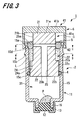
- FIG. 3 is a cross-sectional view taken along the line AA shown in FIG.
- the vial 1 which shows 1st Embodiment of a chemical
- the outer member 2 includes an outer member main body 11, a sealing body 12 that seals a mouth portion 16 described later of the outer member main body 11, and a cap 13 that is fixed to the mouth portion 16. ing.
- the outer member main body 11 is preferably a transparent or translucent one in order to confirm the mixing of foreign substances, the reaction when mixing a plurality of chemicals, and the like.
- the material of the outer member main body 11 include polyvinyl chloride, polyethylene, polypropylene, cyclic polyolefin, polystyrene, poly- (4-methylpentene-1), polycarbonate, acrylic resin, acrylonitrile-butadiene-styrene copolymer ( (ABS resin), polyester such as polybutylene terephthalate (PBT), butadiene-styrene copolymer, various resins such as polyamide (for example, nylon 6, nylon 6,6, nylon 6,10, nylon 12).
- ABS resin acrylonitrile-butadiene-styrene copolymer
- PBT polybutylene terephthalate
- polyamide for example, nylon 6, nylon 6,6, nylon 6,10, nylon 12
- the outer member main body 11 has a cylindrical portion 15 that is a substantially cylindrical cylindrical body, and a mouth portion 16 provided at one end portion (lower end portion) of the cylindrical portion 15 in the axial direction.
- the other end part (upper end part) of the external material body 11 in the axial direction is opened, and serves as an insertion port into which the inner member 3 is inserted.
- the mouth portion 16 is formed in a cylindrical body having a smaller diameter than the cylindrical portion 15.
- a retaining protrusion 15 a and an engaging protrusion 15 b are formed on the outer peripheral surface of the cylindrical portion 15.
- the retaining protrusion 15a is provided at the upper end of the cylindrical portion 15, and is formed in an annular shape protruding outward in the radial direction of the cylindrical portion 15 (see FIG. 2).
- the retaining protrusion 15a engages with a lock claw 42, which will be described later, of the lock member 6, and restricts the lock member 6 and the inner member 3 from moving upward in the axial direction of the outer member 2.
- the engaging protrusion 15b is provided below the retaining protrusion 15a, and is formed in a substantially annular shape protruding outward in the radial direction of the cylindrical portion 15 (see FIG. 2).
- the engagement protrusion 15b moves the lock member 6 and the inner member 3 downward in the axial direction of the outer member 2 and arranges them at a lock position (see FIG. 6B) to be described later. Engage with. As a result, the lock member 6 and the inner member 3 cannot move upward from the lock position.
- the notch 18 is formed in the engagement protrusion 15b. These four cutouts 18 are provided at predetermined intervals in the circumferential direction of the cylindrical portion 15, and are each sized to allow the lock claw 42 of the lock member 6 to pass therethrough. By rotating the lock member 6 in the circumferential direction of the cylindrical portion 15 and causing the lock claw 42 to face the notch 18, the lock member 6 and the inner member 3 can move upward from the lock position. That is, the notch 18 shows a specific example of the unlocking mechanism according to the present invention.
- a first seal fixing groove 15 c and a second seal fixing groove 15 d that are continuous in the circumferential direction of the cylindrical portion 15 are provided on the inner peripheral surface of the cylindrical portion 15.
- the first seal fixing groove 15 c is formed in an intermediate portion of the cylindrical portion 15 in the axial direction.
- the first seal member 4 is fitted and fixed in the first seal fixing groove 15c.
- the first seal member 4 is in liquid-tight contact with the cylindrical portion 15.
- the second seal fixing groove 15 d is formed at the upper end of the cylindrical portion 15.
- the second seal member 5 is fitted and fixed in the second seal fixing groove 15d.
- the second seal member 5 is in liquid-tight contact with the cylindrical portion 15.
- the seal members 4 and 5 may be fixed to the seal fixing grooves 15c and 15d only by fitting, but may be fixed more firmly using, for example, an adhesive.
- the sealing body 12 is liquid-tightly fitted into the cylindrical hole of the mouth portion 16 and seals the opening at the lower end of the outer member main body 11.
- the sealing body 12 forms the bottom of the outer member 2.
- the sealing body 12 can be punctured by a needle tube such as a syringe.
- a needle tube such as a syringe.
- the sealed body 12 is one that is punctured with a needle tube, but is not limited to this.
- a valve body capable of connecting pipes such as various medical devices and infusion containers may be used.
- the valve body has, for example, a slit and is deformed by insertion of the tubular body to open the slit, or is inserted into the slit to communicate with the internal space of the outer member 2. There is.
- the material of the sealing body 12 is not particularly limited, but is preferably formed of an elastic material in order to improve liquid tightness with the mouth portion 16.
- elastic materials include various rubber materials such as natural rubber, butyl rubber, isoprene rubber, butadiene rubber, styrene-butadiene rubber, silicone rubber, isobutylene rubber, polyurethane-based, polyester-based, polyamide-based, and olefin-based materials. , Various thermoplastic elastomers such as styrene, or mixtures thereof.
- the cap 13 is fitted or screwed to the outer peripheral portion of the mouth portion 16 to prevent the sealing body 12 from being detached from the mouth portion 16.
- the method for fixing the cap 13 is not limited to fitting or screwing.
- various other fixing methods such as caulking, fusing, and adhesion using an adhesive can be used.
- various resin materials such as a thermoplastic resin, a metal, etc. can be mentioned.
- the inner member 3 is inserted into the cylindrical portion 15 of the outer member 2.
- the inner member 3 is composed of an upper cylindrical portion 21 and a lower cylindrical portion 22 continuous with the upper cylindrical portion 21.
- the axis of the lower cylindrical part 22 coincides with the axis of the upper cylindrical part 21.
- the diameters of the upper cylindrical portion 21 and the lower cylindrical portion 22 are smaller than the inner diameter of the cylindrical portion 15 in the outer member 2.
- the diameter of the upper cylindrical portion 21 is smaller than the diameter of the lower cylindrical portion 22.
- the upper cylindrical portion 21 has an upper surface 21 a that is one end in the axial direction and an outer peripheral surface 21 b, and the lower end is continuous with the lower cylindrical portion 22.
- the lower cylindrical portion 22 has an upper surface 22a that is one end in the axial direction, a lower surface 22b that is the other end in the axial direction, and an outer peripheral surface 22c. Since the upper end of the lower cylindrical portion 22 is continuous with the lower end of the upper cylindrical portion 21, the upper surface 22a of the lower cylindrical portion 22 is formed in an annular shape having an appropriate width.
- the inner member 3 is provided with an inflow path 24 and an outflow path 25.
- the inflow path 24 and the outflow path 25 communicate a first storage chamber 31 and a second storage chamber 32 (described later) formed between the inner member 3 and the outer member 2.
- the inflow path 24 is formed by providing a groove portion along the axial direction of the lower cylindrical portion 22 on the outer peripheral surface 22 c of the lower cylindrical portion 22.
- the inflow path 24 is formed from the upper surface 22 a of the lower cylindrical portion 22 to the middle portion of the lower cylindrical portion 22.
- an inclined surface 24 a that is inclined with respect to the axial direction of the lower cylindrical portion 22 is formed in the lower portion of the inflow passage 24.
- the outflow passage 25 is formed by providing a through-hole penetrating the upper cylindrical portion 21 and the lower cylindrical portion 22.
- the outflow passage 25 has two openings 25a on the outer peripheral surface 21b of the upper cylindrical portion 21 and one opening 25b on the lower surface 22b of the lower cylindrical portion 22 opposite to the upper cylindrical portion 21. ing.
- the inner member 3 is inserted into the cylindrical portion 15 of the outer member 2 from the lower cylindrical portion 22 side.
- a first storage chamber 31 and a second storage chamber 32 are formed between the inner member 3 and the outer member 2 by the first seal member 4 and the second seal member 5.
- the first storage chamber 31 is formed between the lower surface 22 b of the lower cylindrical portion 22 and the sealing body 12 (bottom portion) of the outer member 2
- the second storage chamber 32 includes the outer peripheral surface 21 b of the upper cylindrical portion 21 and the lower side. It is formed between the outer peripheral surface 22 c of the side cylindrical portion 22 and the inner peripheral surface of the cylindrical portion 15 in the outer member 2.
- FIG. 4 is a cross-sectional view taken along line BB shown in FIG.
- the first seal member 4 fixed to the cylindrical portion 15 is in liquid-tight contact with the outer peripheral surface 22 c of the lower cylindrical portion 22 below the inflow path 24.
- the 1st storage chamber 31 and the 2nd storage chamber 32 are partitioned liquid-tightly, the inflow path 24 is sealed liquid-tightly.
- FIG. 5 is a cross-sectional view taken along the line CC shown in FIG.
- the second seal member 5 fixed to the cylindrical portion 15 is in liquid-tight contact with the outer peripheral surface 21 b of the upper cylindrical portion 21 in the inner member 3, and the opening 25 a of the outflow passage 25 is provided. cover. Accordingly, the second seal member 5 seals the upper portion of the second storage chamber 32 in a liquid-tight manner and also seals the opening 25a of the outflow passage 25 in a liquid-tight manner.
- the state where the inflow passage 24 is sealed by the first seal member 4 and the outflow passage 25 is sealed by the second seal member 5 is defined as a partition state.
- the vial 1 is stored in a storage place such as a refrigerator in a partitioned state.
- the powdery medicine P is housed in the first housing chamber 31 of the partitioned vial 1, and the liquid medicine L is housed in the second housing chamber 32. That is, the medicine P indicates the first medicine according to the present invention, and the medicine L indicates the second medicine according to the present invention.
- medical agent accommodated in the 1st storage chamber 31 is not limited to powder form.
- the first drug according to the present invention may be a single solid or a liquid. It is preferable that the 2nd chemical
- the inner member 3 is disposed at a lock position (see FIG. 6B) described later to place the vial 1 in a communicating state, the second medicine flows into the first storage chamber 31 through the inflow path 24. Therefore, it is preferable that the 2nd chemical
- first seal member 4 and the second seal member 5 are preferably formed of an elastic material in order to improve the liquid tightness with the outer member 2 and the inner member 3.
- elastic materials include various rubber materials such as natural rubber, butyl rubber, isoprene rubber, butadiene rubber, styrene-butadiene rubber, silicone rubber, isobutylene rubber, polyurethane-based, polyester-based, polyamide-based, and olefin-based materials.
- Various thermoplastic elastomers such as styrene, or mixtures thereof.
- the lock member 6 includes an operation unit 41 and four lock claws 42 continuous to the operation unit 41.
- the operation unit 41 includes a side plate 41a formed in a cylindrical body and an upper plate 41b that closes one end (upper end) in the axial direction of the side plate 41a.
- the inner diameter of the side plate 41 a is larger than the outer diameter of the cylindrical portion 15 of the outer member 2.
- the inner surface of the upper plate 41b is fixed to the upper surface 21a of the upper cylindrical portion 21 of the inner member 3 by a fixing method such as a fixing screw or an adhesive.
- the four lock claws 42 are continuous with the other end (lower end) of the side plate 41a in the axial direction, and protrude in the axial direction of the side plate 41a. These four locking claws 42 engage with the retaining protrusion 15a of the outer member 2 when the vial 1 is in a partitioned state, and prevent the inner member 3 from moving upward in the axial direction of the outer member 2. To do.
- the four lock claws 42 engage with the engaging protrusions 15b of the outer member 2 when the vial 1 is in a communicating state, and prevent the inner member 3 from moving upward in the axial direction of the outer member 2. . That is, the four locking claws 42 and the engaging protrusions 15b of the outer member 2 show a specific example of the locking part according to the present invention. Further, when the vial 1 is in a communicating state, the inner surface of the upper plate 41 b of the operation unit 41 comes into contact with the upper end of the cylindrical portion 15 of the outer member 2, and the inner member 3 cannot move downward in the axial direction of the outer member 2. Therefore, in the communication state of the vial 1, the lock member 6 prevents the inner member 3 from moving in the axial direction of the outer member 2.
- medical agent P is thrown in in the cylinder part 15 of the outer member 2, and it arrange
- the drug P is a freeze-dried drug
- the drug P is freeze-dried.
- the outer member 2 is brought into contact with the cooling unit of the freeze-dryer to freeze-dry the drug P in the outer member 2.
- the inner member 3 is inserted into the cylindrical portion 15 of the outer member 2, and the first seal member 4 comes into liquid-tight contact under the inflow path 24 in the outer peripheral surface 22 c of the lower cylindrical portion 22. Push in. Thereby, the 1st storage chamber 31 which accommodated the chemical
- the medicine L is injected between the inner surface of the cylindrical portion 15 in the outer member 2 and the outer peripheral surfaces 21 b and 22 c of the inner member 3.
- the second seal member 5 is fitted and fixed in the second seal fixing groove 15 d provided in the cylindrical portion 15 of the outer member 2. Accordingly, the second seal member 5 is in liquid-tight contact with the outer peripheral surface 21b of the upper cylindrical portion 21 in the inner member 3 and covers the opening 25a of the outflow passage 25.
- the second storage chamber 32 that contains the drug L and is sealed is formed.
- the upper plate 41b of the lock member 6 is fixed to the upper surface 21a of the inner member 3 by a fixing method such as a fixing screw or an adhesive. Thereby, the assembly of the vial 1 is completed.
- the lock claw 42 of the lock member 6 engages with the retaining protrusion 15 a of the outer member 2 and prevents the inner member 3 from moving upward in the axial direction of the outer member 2.
- the assembled vial 1 is in a partitioned state in which the first storage chamber 31 and the second storage chamber 32 are liquid-tightly partitioned.
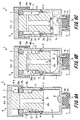
- FIG. 6A is a cross-sectional view showing a partition state of the vial 1.
- FIG. 6B is an explanatory view showing a state in which the medicine L stored in the second storage chamber 32 in the communication state of the vial 1 is injected into the first storage chamber 31.
- FIG. 6C is an explanatory view showing a state where the medicine L is injected into the first storage chamber 31.
- the partitioned vial 1 (see FIG. 6) is placed on the work table S.
- the vial 1 is in a partitioned state
- the first storage chamber 31 and the second storage chamber 32 are partitioned in a liquid-tight manner, and the drug L and the drug P are stored in the vial 1 in an independent state.
- the operation part 41 of the lock member 6 is pressed, and the lock member 6 and the inner member 3 are moved downward in the axial direction of the outer member 2.
- the inner surface of the upper plate 41b of the lock member 6 contacts the upper end of the cylindrical portion 15 of the outer member 2, and the lock claw 42 engages with the engaging protrusion 15b of the outer member 2 (see FIG. 6B).
- the lock member 6 and the inner member 3 are disposed at the lock position, and the inner member 3 cannot move in the axial direction of the outer member 2.
- the inflow path 24 of the inner member 3 faces the first seal member 4 and the sealing of the inflow path 24 is released. Further, the opening 25a of the outflow passage 25 is detached from the second seal member 5, and the sealing of the outflow passage 25 is released. As a result, the first storage chamber 31 and the second storage chamber 32 communicate with each other through the inflow path 24 and the outflow path 25, and the vial 1 enters a communication state.
- the medicine L stored in the second storage chamber 32 is injected into the first storage chamber 31 through the inflow passage 24.
- the air in the first storage chamber 31 flows into the second storage chamber 32 through the outflow passage 25.
- the injection of the medicine L is not hindered by the air pressure in the first storage chamber 31, and the medicine L can be smoothly injected into the first storage chamber 31.
- the drug L that has passed through the inflow path 24 flows along the inner peripheral surface of the cylindrical portion 15 to the first storage chamber 31, and thus is not directly dropped onto the drug P. As a result, it is possible to prevent the mixed medicine obtained by mixing the medicine L and the medicine P from foaming.
- the drug L and the drug P are mixed by grasping and shaking the vial 1.
- movement which shakes the vial 1 can be abbreviate
- the drug L and the drug P can be mixed and then returned to the partitioning state.
- the lock member 6 In order to return the vial 1 from the communication state to the partitioning state, the lock member 6 is rotated in the circumferential direction of the cylindrical portion 15 in the outer member 2, and the lock claw 42 is notched 18 in the engagement protrusion 15b (see FIG. 1). To face. Thereby, the lock of the lock member 6 and the inner member 3 is released, and the lock member 6 and the inner member 3 can be moved upward in the axial direction of the outer member 2. When the lock member 6 and the inner member 3 are moved upward in the axial direction of the outer member 2, the vial 1 returns to the partition state.
- the drug L can be injected into the first storage chamber 31 simply by pressing the operating portion 41 of the lock member 6 to bring it into communication, and the drug L and the drug P are mixed. Work can be done easily.
- the vial 1 is placed on the work table S and the lock member 6 is pressed. However, the vial 1 may be held by hand and the lock member 6 may be pressed.
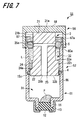
- FIG. 7 is a cross-sectional view showing a second embodiment of the drug container of the present invention.
- the vial 51 showing the second embodiment of the drug container has the same configuration as the vial 1 of the first embodiment.
- the only difference between the vial 51 and the vial 1 is the outer member 52 and the lock member 56. Therefore, here, the outer member 52 and the lock member 56 will be described, and the same reference numerals will be given to portions common to the vial 1 and redundant description will be omitted.
- the outer member 52 of the vial 51 includes an outer member main body 61 having a cylindrical portion 65 and a mouth portion 16, a sealing body 12, and a cap 13.
- the cylinder part 65 is a substantially cylindrical cylinder.
- a male thread portion 65 a is provided on the outer peripheral surface of the cylindrical portion 65.
- the male screw portion 65 a is formed on the upper portion of the cylindrical portion 65 and is screwed into a female screw portion 67 a (described later) of the lock member 56.
- the lock member 56 includes a side plate 67 formed in a cylindrical body and an upper plate 68 that closes one end (upper end) of the side plate 67 in the axial direction.
- the inner diameter of the side plate 67 is larger than the outer diameter of the cylindrical portion 65 of the outer member 52.
- On the inner peripheral surface of the side plate 67 a female screw portion 67a that is screwed into the male screw portion 65a of the cylindrical portion 65 is formed.
- the upper plate 68 is an operation unit for pressing the inner member 3.
- the inner surface of the upper plate 68 is fixed to the upper surface 21a of the upper cylindrical portion 21 of the inner member 3 by a fixing method such as a fixing screw or an adhesive.
- the inner member 3 is moved in the axial direction of the outer member 52 by rotating the lock member 56 in the circumferential direction of the cylindrical portion 65 of the outer member 52.
- a stopper (not shown) that applies resistance to the rotation of the lock member 56 is attached to the vial 51 assembled in a partitioned state.
- the lock member 56 In order to change the vial 51 from the partitioned state to the communicating state, the lock member 56 is rotated against the resistance force of the stopper. As a result, the lock member 56 and the inner member 3 move downward in the axial direction of the outer member 52 and are disposed at the lock position. At this time, the screwing of the female screw portion 67a of the lock member 56 and the male screw portion 65a of the cylinder portion 65 is finished, and the lock member 56 and the inner member 3 cannot move downward in the axial direction of the outer member 2. That is, the external thread portion 65a of the outer member 52 and the internal thread portion 67a of the lock member 56 show a second specific example of the lock portion according to the present invention.
- the inflow path 24 of the inner member 3 faces the first seal member 4 and the sealing of the inflow path 24 is released. Also.
- the opening 25a of the outflow passage 25 is detached from the second seal member 5, and the sealing of the outflow passage 25 is released.
- the first storage chamber 31 and the second storage chamber 32 communicate with each other through the inflow path 24 and the outflow path 25, and the vial 51 enters a communication state.
- the drug L can be injected into the first storage chamber 31 simply by rotating the lock member 6 with respect to the outer member 2 so as to be in communication with each other. Can be easily mixed.
- the present invention is not limited to the embodiments described above and shown in the drawings, and various modifications can be made without departing from the scope of the invention described in the claims.
- the outer member main body 11 (61) has the mouth portion 16, but the outer member main body according to the present invention may not have the mouth portion.
- the one end part (lower end part) of a cylinder part is sealed with a sealing body.
- the inflow path 24 is formed by providing one groove having an appropriate width in the inner member 3, but the number of inflow paths according to the present invention may be two or more.
- the inflow passage according to the present invention can be formed by providing a groove on the entire circumference of the lower cylindrical portion 22 in the inner member 3. In this case, the second medicine is injected into the first storage chamber along the entire inner peripheral surface of the outer member 2, and the injection time can be shortened while suppressing foaming.
- first seal member 4 and the second seal member 5 are fixed to the inner periphery of the outer member 2 (52).
- first seal member and the second seal member according to the present invention are used.
- the seal member may be fixed to the inner member or the operation unit.
- a groove serving as an inflow path may be provided in the outer member.
- the cylindrical portion 15 and the mouth portion 16 of the outer member 3 are cylindrical.
- the outer member according to the present invention may be a cylindrical body, for example, a triangular or quadrangular square tube. It may be a body.
- the inner member 3 is a substantially cylindrical body.
- the first storage chamber and the second storage chamber are inserted between the outer member and the outer member. If it can form, it can be made into arbitrary shapes.
- the first seal member 4 and the fifth seal member 5 are formed of an elastic material, and are brought into contact with the inner member 3 so as to be liquid-tightly adhered thereto.
- the second storage chamber 32 is provided.
- the seal member according to the present invention may be formed of a hard member having appropriate rigidity and may have a screw portion.
- the outer member or the inner member is provided with a screw portion in which the screw portion provided in the seal member is screwed in a liquid-tight manner.
- the seal member according to the present invention may be configured by providing an outer member-side screw portion on the outer member, and providing an inner member-side screw portion that is liquid-tightly engaged with the outer member-side screw portion on the inner member. Good. In this case, when the outer member side screw portion and the inner member side screw portion are disengaged, the first storage chamber and the second storage chamber communicate with each other through the outflow path and the inflow path.
- the present invention can be used in a drug container that contains two drugs independently and mixes them before use.
Landscapes
- Health & Medical Sciences (AREA)
- Pharmacology & Pharmacy (AREA)
- Life Sciences & Earth Sciences (AREA)
- Animal Behavior & Ethology (AREA)
- General Health & Medical Sciences (AREA)
- Public Health (AREA)
- Veterinary Medicine (AREA)
- Medical Preparation Storing Or Oral Administration Devices (AREA)
Abstract
本発明は、それぞれ独立して収容した薬剤の混和作業を簡単に行うことができる薬剤容器を提供する。本発明の薬剤容器(バイアル(1))は、開口部と底部を有する筒状体の外部材(2)と、外部材(2)に挿入される内部材(3)と、外部材(2)の内周に設けられ、軸方向に間隔をおいて配置された第1及び第2のシール部材(4),(5)を備える。また、外部材(2)の底部と内部材(3)と第1のシール部材(4)とで形成される第1収容室(31)と、第1及び第2のシール部材(4),(5)と内部材(3)とで形成される第2収容室(32)と、操作部(41)と、収容室(31),(32)を連通させる流入路(24)及び流出路(25)を備える。バイアル(1)の初期状態において、流入路(24)と流出路(25)は、シール部材(4),(5)で閉塞される。そして、内部材(3)を外部材(2)に対して軸方向に移動させ、流入路(24)及び流出路(25)を開放させると、第1収容室(31)と第2収容室(32)が連通する。
Description
本発明は、2つの薬剤を独立して収容し、使用前に混和させる薬剤容器に関する。
薬剤を保存するための薬剤容器としては、例えば、バイアルが用いられている。一般的なバイアルは、ガラス製の瓶と、この瓶の開口部を封止するゴムキャップから構成されている。
このようなバイアルは、例えば、特許文献1に開示されている。医療機関では、特許文献1に開示されたようなバイアルに粉体状の薬剤を収容して保存し、使用する際に溶解液を注入してバイアル内で薬剤と溶解液を混和することがある。
粉末状の薬剤を溶解液で溶解するには、まず粉末状の薬剤が収容されたバイアル内に溶解液を注入して薬剤を溶解することとなる。例えば、予めバイアル内から所定量の空気を抜いた後に溶解液をバイアル内に注入し、薬剤と溶解液との混和を行う。あるいは、バイアル内への溶解液の注入時に、溶解液の注入とバイアル内の空気の吸引を交互に繰り返しながら所定量の溶解液を注入し、薬剤と溶解液との混和を行う。
上述したように、特許文献1に開示されたようなバイアルでは、粉体状の薬剤と溶解液とを混和させるために複数の作業が必要になり、混和作業が煩雑になってしまう。そこで、1個のパッケージ内に独立した2つの収容室を有するバイアル(薬剤容器)が開発されている。
このような2つの収容室を有するバイアルは、例えば、特許文献2に開示されている。この特許文献2に開示されたバイアルは、破裂可能な弁(隔壁)によって隔たれた第1室及び第2室を備えており、第1室が第2室に対して入れ子式に構成されている。この特許文献2に開示されたバイアルでは、第2室に対して第1室を挿入し、第2室内に収容された流体状の薬剤の流体圧で弁が破裂し、両室に収容されていた薬剤が第1室内で混合されるようになっている。
しかしながら、特許文献2に開示されたバイアルでは、第2室に収容された流体全てを第1室に注入するまで、第1室を形成するシリンダに対して第2室を形成する容器を押圧し続けなければならなかった。そのため、複数のバイアルに対してそれぞれ混和作業を行う場合は、作業が煩雑になると共に作業時間が長時間になるという問題があった。
本発明は、上述の点に鑑み、それぞれ独立して収容した薬剤の混和作業を簡単に行うことができる薬剤容器を提供することを目的とする。
上記目的を達成するため、本発明の薬剤容器は、外部材と、内部材と、第1のシール部材及び第2のシール部材と、第1収容室と、第2収容室と、内部材を押圧するための操作部と、流入路及び流出路とを備えている。
外部材は、開口部と底部とを有する筒状体からなり、内部材は、外部材に挿入される。
第1のシール部材及び第2のシール部材は、外部材の内周または/及び内部材の外周に設けられ、軸方向に間隔をおいて配置される。
第1収容室は、外部材の底部と内部材と外部材の底部側に配置される第1のシール部材とで形成され、第2収容室は、第1及び第2のシール部材と内部材とで形成される。
流入路及び流出路は、第1収容室と第2収容室とを連通させる。
この流入路及び流出路は、初期状態において、第1のシール部材及び第2のシール部材で閉塞される。そして、操作部を操作することにより、内部材を外部材に対して軸方向に移動させ、流入路及び流出路を開放させることで第1収容室と第2収容室とが連通する。
外部材は、開口部と底部とを有する筒状体からなり、内部材は、外部材に挿入される。
第1のシール部材及び第2のシール部材は、外部材の内周または/及び内部材の外周に設けられ、軸方向に間隔をおいて配置される。
第1収容室は、外部材の底部と内部材と外部材の底部側に配置される第1のシール部材とで形成され、第2収容室は、第1及び第2のシール部材と内部材とで形成される。
流入路及び流出路は、第1収容室と第2収容室とを連通させる。
この流入路及び流出路は、初期状態において、第1のシール部材及び第2のシール部材で閉塞される。そして、操作部を操作することにより、内部材を外部材に対して軸方向に移動させ、流入路及び流出路を開放させることで第1収容室と第2収容室とが連通する。
上記構成の薬剤容器では、内部材を外部材の軸方向に移動させて、流入路及び流出路を開放させるにより第1収容室及び第2収容室を連通させる。これにより、第2収容室を第1収容室よりも上方に位置させておけば、第2収容室に収納された薬剤が流入路を通って第1収容室に流れる。一方、第1収容室の空気は、流出路を通って第2収容室に流れる。これにより、薬剤を第1収納室に円滑に注入することができる。
また、内部材を外部材の軸方向に移動させるだけで、第2収容室の薬剤を第1収納室に注入して第1収納室の第1薬剤と混和させることができるため、混和作業を簡単に行うことができる。
また、内部材を外部材の軸方向に移動させるだけで、第2収容室の薬剤を第1収納室に注入して第1収納室の第1薬剤と混和させることができるため、混和作業を簡単に行うことができる。
上記構成の薬剤容器によれば、第1収容室と第2収容室にそれぞれ収容した薬剤の混和作業を簡単に行うことができる。
以下、本発明の薬剤容器の実施形態について、図1~図7を参照して説明する。なお、各図において共通の部材には、同一の符号を付している。また、本発明は、以下の形態に限定されるものではない。
1.第1の実施の形態
[薬剤容器の構成例]
まず、本発明の薬剤容器の第1の実施の形態について、図1~図3を参照して説明する。
図1は、薬剤容器の第1の実施の形態を示すバイアルの斜視図である。図2は、バイアルの分解斜視図である。図3は、図1に示すA-A線に沿う断面図である。
[薬剤容器の構成例]
まず、本発明の薬剤容器の第1の実施の形態について、図1~図3を参照して説明する。
図1は、薬剤容器の第1の実施の形態を示すバイアルの斜視図である。図2は、バイアルの分解斜視図である。図3は、図1に示すA-A線に沿う断面図である。
図1及び図2に示すように、薬剤容器の第1の実施の形態を示すバイアル1は、外部材2と、内部材3と、第1のシール部材4と、第2のシール部材5と、ロック部材6とを備えている。
図3に示すように、外部材2は、外部材本体11と、この外部材本体11の後述する口部16を封止する封体12と、口部16に固定されるキャップ13から構成されている。
外部材本体11は、異物の混入や、複数の薬剤を混和する際の反応等を確認するために、透明又は半透明なものを用いることが好ましい。この外部材本体11の材料としては、例えば、ポリ塩化ビニル、ポリエチレン、ポリプロピレン、環状ポリオレフィン、ポリスチレン、ポリ-(4-メチルペンテン-1)、ポリカーボネート、アクリル樹脂、アクリロニトリル-ブタジエン-スチレン共重合体(ABS樹脂)、ポリブチレンテレフタレート(PBT)等のポリエステル、ブタジエン-スチレン共重合体、ポリアミド(例えば、ナイロン6、ナイロン6・6、ナイロン6・10、ナイロン12)のような各種樹脂が挙げられ、その中でも、成形が容易であるという点で、ポリプロピレン、環状ポリオレフィン、ポリエステル、ポリ-(4-メチルペンテン-1)、のような樹脂を用いることが好ましい。
外部材本体11は、略円筒状の筒体である筒部15と、この筒部15の軸方向の一端部(下端部)に設けられた口部16を有している。外部材本体11の軸方向の他端部(上端部)は、開口されており、内部材3を挿入する挿入口になっている。口部16は、筒部15よりも小さい径の円筒体に形成されている。
筒部15の外周面には、抜け止め突部15aと、係合突部15bが形成されている。抜け止め突部15aは、筒部15の上端部に設けられており、筒部15の半径外方向に突出する環状に形成されている(図2参照)。この抜け止め突部15aは、ロック部材6の後述するロック爪42に係合し、ロック部材6及び内部材3が外部材2の軸方向の上方へ移動することを制限する。
係合突部15bは、抜け止め突部15aの下方に設けられており、筒部15の半径外方向に突出する略環状に形成されている(図2参照)。この係合突部15bは、ロック部材6及び内部材3を外部材2の軸方向の下方へ移動させて後述するロック位置(図6B参照)に配置したときに、ロック部材6のロック爪42に係合する。これにより、ロック部材6及び内部材3は、ロック位置から上方へ移動できなくなる。
係合突部15bには、4つの切欠き18が形成されている。これら4つの切欠き18は、筒部15の周方向に所定の間隔をあけて設けられており、それぞれロック部材6のロック爪42が通過可能な大きさになっている。ロック部材6を筒部15の周方向に回転さてロック爪42を切欠き18に対向させることにより、ロック部材6及び内部材3は、ロック位置から上方へ移動可能になる。すなわち、切欠き18は、本発明に係るロック解除機構の一具体例を示す。
筒部15の内周面には、筒部15の周方向に連続する第1のシール固定用溝15c及び第2のシール固定用溝15dが設けられている。
第1のシール固定用溝15cは、筒部15の軸方向の中間部に形成されている。この第1のシール固定用溝15cには、第1のシール部材4が嵌合されて固定される。そして、第1のシール部材4は、筒部15に液密に接触する。
第1のシール固定用溝15cは、筒部15の軸方向の中間部に形成されている。この第1のシール固定用溝15cには、第1のシール部材4が嵌合されて固定される。そして、第1のシール部材4は、筒部15に液密に接触する。
第2のシール固定用溝15dは、筒部15の上端部に形成されている。この第2のシール固定用溝15dには、第2のシール部材5が嵌合されて固定される。そして、第2のシール部材5は、筒部15に液密に接触する。
これらシール部材4,5は、嵌合のみでシール固定用溝15c,15dに固定してもよいが、例えば、接着剤などを用いてより強固に固定してもよい。
これらシール部材4,5は、嵌合のみでシール固定用溝15c,15dに固定してもよいが、例えば、接着剤などを用いてより強固に固定してもよい。
図3に示すように、封体12は、口部16の筒孔に液密に嵌合しており、外部材本体11の下端の開口を封止する。この封体12は、外部材2の底部を形成している。また、封体12は、注射器等の針管が穿刺可能なものである。この封体12に針管を刺し通すことで、外部材2の内部空間と注射器等の医療機器が連通する。これにより、バイアル1内の混和済み薬剤を吸引することができる。
なお、本例では、封体12として針管が穿刺されるものを適用したが、これに限定されるものではない。封体12としては、例えば、各種医療機器や輸液容器等の管体を接続可能な弁体であってもよい。この弁体は、例えば、スリットを有しており、管体の挿入により変形してスリットが開口するものや、管体自体をスリットに挿入することで外部材2の内部空間に連通させるものなどがある。
封体12の材料としては、特に限定されないが、口部16との液密性を良好にするために弾性材料で形成することが好ましい。このような弾性材料としては、例えば、天然ゴム、ブチルゴム、イソプレンゴム、ブタジエンゴム、スチレン-ブタジエンゴム、シリコーンゴム、イソブチレンゴムのような各種ゴム材料や、ポリウレタン系、ポリエステル系、ポリアミド系、オレフィン系、スチレン系等の各種熱可塑性エラストマ、あるいはそれらの混合物を挙げることができる。
キャップ13は、口部16の外周部に嵌合または螺合しており、封体12が口部16から外れることを防止している。なお、キャップ13の固定方法は、嵌合または螺合に限定されるものではない。キャップ13の固定方法としては、カシメ、融着や、接着剤を用いた接着等その他各種の固定方法を用いることができる。
また、キャップ13の材料としては、熱可塑性樹脂などの各種樹脂材料や、金属等を挙げることができる。
また、キャップ13の材料としては、熱可塑性樹脂などの各種樹脂材料や、金属等を挙げることができる。
内部材3は、外部材2における筒部15の内部に挿入される。この内部材3は、上側円柱部21と、この上側円柱部21に連続する下側円柱部22とから構成されている。
下側円柱部22の軸心は、上側円柱部21の軸心に一致している。そして、上側円柱部21及び下側円柱部22の径は、外部材2における筒部15の内径よりも小さくなっている。また、上側円柱部21の径は、下側円柱部22の径よりも小さくなっている。
上側円柱部21は、軸方向の一端である上面21aと、外周面21bを有しており、下端が下側円柱部22に連続している。一方、下側円柱部22は、軸方向の一端である上面22aと、軸方向の他端である下面22bと、外周面22cを有している。下側円柱部22の上端は、上側円柱部21の下端に連続しているため、下側円柱部22の上面22aは、適当な幅を有する環状に形成されている。
図3に示すように、内部材3には、流入路24及び流出路25が設けられている。これら流入路24及び流出路25は、内部材3と外部材2との間に形成される後述する第1収容室31及び第2収容室32を連通させる。
流入路24は、下側円柱部22の外周面22cに下側円柱部22の軸方向に沿った溝部を設けることにより形成されている。この流入路24は、下側円柱部22の上面22aから下側円柱部22の中間部まで形成されている。また、流入路24の下部には、下側円柱部22の軸方向に対して傾斜する傾斜面24aが形成されている。
流出路25は、上側円柱部21及び下側円柱部22を貫通する貫通孔を設けることにより形成されている。この流出路25は、上側円柱部21の外周面21bに2箇所の開口部25aと、下側円柱部22の上側円柱部21とは反対側の下面22bに1箇所の開口部25bを有している。
内部材3は、下側円柱部22側から外部材2の筒部15内に挿入される。これにより、内部材3と外部材2との間には、第1のシール部材4及び第2のシール部材5によって第1収容室31及び第2収容室32が形成される。
第1収容室31は、下側円柱部22の下面22bと外部材2の封体12(底部)との間に形成され、第2収容室32は、上側円柱部21の外周面21b及び下側円柱部22の外周面22cと外部材2における筒部15の内周面との間に形成される。
第1収容室31は、下側円柱部22の下面22bと外部材2の封体12(底部)との間に形成され、第2収容室32は、上側円柱部21の外周面21b及び下側円柱部22の外周面22cと外部材2における筒部15の内周面との間に形成される。
図4は、図3に示すB-B線に沿った横断面図である。
図4に示すように、筒部15に固定された第1のシール部材4は、流入路24の下方において、下側円柱部22の外周面22cに液密に接触する。そして、第1収容室31と第2収容室32とを液密に仕切ると共に、流入路24を液密に封止する。
図4に示すように、筒部15に固定された第1のシール部材4は、流入路24の下方において、下側円柱部22の外周面22cに液密に接触する。そして、第1収容室31と第2収容室32とを液密に仕切ると共に、流入路24を液密に封止する。
図5は、図3に示すC-C線に沿った横断面図である。
図5に示すように、筒部15に固定された第2のシール部材5は、内部材3における上側円柱部21の外周面21bに液密に接触すると共に、流出路25の開口部25aを覆う。これにより、第2のシール部材5は、第2収容室32の上部を液密に封止すると共に、流出路25の開口部25aを液密に封止する。
図5に示すように、筒部15に固定された第2のシール部材5は、内部材3における上側円柱部21の外周面21bに液密に接触すると共に、流出路25の開口部25aを覆う。これにより、第2のシール部材5は、第2収容室32の上部を液密に封止すると共に、流出路25の開口部25aを液密に封止する。
このように、第1のシール部材4により流入路24を封止し、且つ、第2のシール部材5により流出路25を封止した状態(図3参照)を、仕切り状態とする。バイアル1は、仕切り状態で冷蔵室などの保管場所に保管される。
図3に示すように、本実施の形態では、仕切り状態のバイアル1における第1収容室31に粉体状の薬剤Pを収容し、第2収容室32に液体状の薬剤Lを収容する。つまり、薬剤Pは、本発明に係る第1薬剤を示し、薬剤Lは本発明に係る第2薬剤を示す。
なお、第1収容室31に収容する第1薬剤は、粉体状に限定されるものではない。本発明に係る第1薬剤としては、1つの固まりとされた固体であってもよく、また、液体状であってもよい。
第2収容室32に収容する第2薬剤は、液体状であることが好ましい。内部材3を後述するロック位置(図6B参照)に配置させてバイアル1を連通状態にすると、第2薬剤は、流入路24を通って第1収容室31へ流入する。そのため、第2薬剤は、流体状であることが好ましい。
第2収容室32に収容する第2薬剤は、液体状であることが好ましい。内部材3を後述するロック位置(図6B参照)に配置させてバイアル1を連通状態にすると、第2薬剤は、流入路24を通って第1収容室31へ流入する。そのため、第2薬剤は、流体状であることが好ましい。
また、第1のシール部材4及び第2のシール部材5は、外部材2及び内部材3との液密性を良好にするために弾性材料で形成することが好ましい。このような弾性材料としては、例えば、天然ゴム、ブチルゴム、イソプレンゴム、ブタジエンゴム、スチレン-ブタジエンゴム、シリコーンゴム、イソブチレンゴムのような各種ゴム材料や、ポリウレタン系、ポリエステル系、ポリアミド系、オレフィン系、スチレン系等の各種熱可塑性エラストマ、あるいはそれらの混合物を挙げることができる。
次に、ロック部材6について図2及び図3を参照して説明する。
ロック部材6は、操作部41と、この操作部41に連続する4つのロック爪42から構成されている。
ロック部材6は、操作部41と、この操作部41に連続する4つのロック爪42から構成されている。
操作部41は、円筒体に形成された側板41aと、この側板41aの軸方向の一端(上端)を塞ぐ上板41bからなっている。側板41aの内径は、外部材2の筒部15の外径よりも大きなっている。上板41bの内面は、内部材3における上側円柱部21の上面21aに固定ねじや接着剤などの固着方法により固定されている。
4つのロック爪42は、側板41aの軸方向の他端(下端)に連続しており、側板41aの軸方向に突出している。これら4つのロック爪42は、バイアル1を仕切り状態にしたときに、外部材2の抜け止め突部15aに係合し、内部材3が外部材2の軸方向の上方へ移動することを防止する。
4つのロック爪42は、バイアル1を連通状態にしたときに、外部材2の係合突部15bに係合し、内部材3が外部材2の軸方向の上方へ移動することを防止する。すなわち、4つのロック爪42と外部材2の係合突部15bは、本発明に係るロック部の一具体例を示す。
また、バイアル1を連通状態にすると、操作部41の上板41bの内面が外部材2における筒部15の上端に当接し、内部材3が外部材2の軸方向の下方へ移動できなくなる。したがって、バイアル1の連通状態において、ロック部材6は、内部材3が外部材2の軸方向へ移動することを防止する。
また、バイアル1を連通状態にすると、操作部41の上板41bの内面が外部材2における筒部15の上端に当接し、内部材3が外部材2の軸方向の下方へ移動できなくなる。したがって、バイアル1の連通状態において、ロック部材6は、内部材3が外部材2の軸方向へ移動することを防止する。
[薬剤容器の組立方法]
次に、バイアル1の組立方法の例について、図3を参照して説明する。
バイアル1を組み立てるには、まず、外部材2の筒部15に設けた第1のシール固定用溝15cに第1のシール部材4を嵌合させて固定する。
次に、バイアル1の組立方法の例について、図3を参照して説明する。
バイアル1を組み立てるには、まず、外部材2の筒部15に設けた第1のシール固定用溝15cに第1のシール部材4を嵌合させて固定する。
次に、外部材2の筒部15内に薬剤Pを投入して底部に配置する。
薬剤Pが凍結乾燥薬剤の場合は、薬剤Pを凍結乾燥する。凍結乾燥工程では、外部材2を凍結乾燥機の冷却部に接触させて外部材2内の薬剤Pを凍結乾燥する。
薬剤Pが凍結乾燥薬剤の場合は、薬剤Pを凍結乾燥する。凍結乾燥工程では、外部材2を凍結乾燥機の冷却部に接触させて外部材2内の薬剤Pを凍結乾燥する。
続いて、内部材3を外部材2の筒部15内に挿入し、第1のシール部材4が、下側円柱部22の外周面22cのうちの流入路24の下方で液密に接触するまで押し込む。これにより、薬剤Pを収容して密閉された第1収容室31が形成される。また、内部材3における上側円柱部21の上部は、外部材2における筒部15の上端から突出した状態になる。
次に、外部材2における筒部15の内面と内部材3の外周面21b,22cとの間に薬剤Lを注入する。
続いて、外部材2の筒部15に設けた第2のシール固定用溝15dに第2のシール部材5を嵌合させて固定する。これにより、第2のシール部材5は、内部材3における上側円柱部21の外周面21bに液密に接触すると共に、流出路25の開口部25aを覆う。その結果、薬剤Lを収容して密閉された第2収容室32が形成される。
続いて、外部材2の筒部15に設けた第2のシール固定用溝15dに第2のシール部材5を嵌合させて固定する。これにより、第2のシール部材5は、内部材3における上側円柱部21の外周面21bに液密に接触すると共に、流出路25の開口部25aを覆う。その結果、薬剤Lを収容して密閉された第2収容室32が形成される。
次に、ロック部材6の上板41bを、内部材3の上面21aに固定ねじや接着剤などの固着方法により固定する。これにより、バイアル1の組み立てが完了する。このとき、ロック部材6のロック爪42は、外部材2の抜け止め突部15aに係合し、内部材3が外部材2の軸方向の上方へ移動することを防止する。組み立てられたバイアル1は、第1収容室31と第2収容室32が液密に仕切られた仕切り状態になっている。
[薬剤容器による薬剤の混和方法]
次に、バイアル1による薬剤Lと薬剤Pの混和方法について、図6を参照して説明する。
図6Aは、バイアル1の仕切り状態を示す断面図である。図6Bは、バイアル1の連通状態にして第2収容室32に収容された薬剤Lが第1収容室31に注入されている状態を示す説明図である。図6Cは、薬剤Lが第1収容室31に注入された状態の説明図である。
次に、バイアル1による薬剤Lと薬剤Pの混和方法について、図6を参照して説明する。
図6Aは、バイアル1の仕切り状態を示す断面図である。図6Bは、バイアル1の連通状態にして第2収容室32に収容された薬剤Lが第1収容室31に注入されている状態を示す説明図である。図6Cは、薬剤Lが第1収容室31に注入された状態の説明図である。
バイアル1によって薬剤Lと薬剤Pを混和させるには、例えば、仕切り状態のバイアル1(図6参照)を作業台Sに載置する。バイアル1が仕切り状態の場合は、第1収容室31と第2収容室32が液密に仕切られており、薬剤Lと薬剤Pは独立した状態でバイアル1内に収容されている。
次に、ロック部材6の操作部41を押圧し、ロック部材6及び内部材3を外部材2の軸方向の下方へ移動させる。これにより、ロック部材6における上板41bの内面が外部材2における筒部15の上端に当接すると共に、ロック爪42が外部材2の係合突部15bに係合する(図6B参照)。その結果、ロック部材6及び内部材3がロック位置に配置され、内部材3は、外部材2の軸方向へ移動できなくなる。
内部材3がロック位置に配置されると、内部材3の流入路24が第1のシール部材4に対向し、流入路24の封止が解除される。また、流出路25の開口部25aが第2のシール部材5から外れ、流出路25の封止が解除される。その結果、第1収容室31と第2収容室32が流入路24及び流出路25によって連通され、バイアル1は連通状態になる。
バイアル1が連通状態になると、第2収容室32に収容されている薬剤Lが流入路24を通って第1収容室31に注入される。このとき、第1収容室31内の空気が流出路25を通って第2収容室32に流れ込む。これにより、第1収容室31内の空気圧によって薬剤Lの注入が阻害されることは無く、薬剤Lを第1収容室31に円滑に注入することができる。
また、流入路24を通った薬剤Lは、筒部15の内周面を伝って第1収容室31に流れるため、薬剤Pに直接滴下されない。その結果、薬剤Lと薬剤Pとを混和した混和薬剤が泡立つことを防止することができる。
バイアル1を連通状態にして所定の時間が経過すると、第2収容室32に収容されていた薬剤Lが全て第1収容室31に注入される(図6C参照)。このとき、流入路24の下部が傾斜面24aになっているので、流入路24に薬剤Lが残留しないようにすることができる。
その後、バイアル1を把持して振ることにより、薬剤Lと薬剤Pを混和させる。なお、薬剤Lを第1収容室31に注入するだけで薬剤Lと薬剤Pが混和する場合は、バイアル1を振る作業を省略することができる。
本実施の形態のバイアル1では、連通状態で薬剤Lと薬剤Pを混和した後に、仕切り状態に戻すことができる。バイアル1を連通状態から仕切り状態に戻すには、ロック部材6を外部材2における筒部15の周方向に回転させて、ロック爪42を係合突部15bの切欠き18(図1参照)に対向させる。これにより、ロック部材6及び内部材3のロックが解除され、ロック部材6及び内部材3を外部材2の軸方向の上方へ移動させることができる。そして、ロック部材6及び内部材3を外部材2の軸方向の上方へ移動させると、バイアル1は仕切り状態に戻る。
本実施の形態のバイアル1によれば、ロック部材6の操作部41を押圧して連通状態にするだけで薬剤Lを第1収容室31に注入することができ、薬剤Lと薬剤Pの混和作業を簡単に行うことができる。なお、本実施の形態では、バイアル1を作業台Sに載置してロック部材6の押圧を行ったが、バイアル1を手で把持してロック部材6の押圧を行ってもよい。
2.第2の実施の形態
[薬剤容器の構成例]
次に、本発明の薬剤容器の第2の実施の形態について、図7を参照して説明する。
図7は、本発明の薬剤容器の第2の実施の形態を示す断面図である。
[薬剤容器の構成例]
次に、本発明の薬剤容器の第2の実施の形態について、図7を参照して説明する。
図7は、本発明の薬剤容器の第2の実施の形態を示す断面図である。
薬剤容器の第2の実施の形態を示すバイアル51は、第1の実施の形態のバイアル1と同様の構成を備えている。このバイアル51がバイアル1と異なるところは、外部材52及びロック部材56のみである。そのため、ここでは、外部材52及びロック部材56について説明し、バイアル1と共通する部分には同一の符号を付して重複した説明を省略する。
図7に示すように、バイアル51の外部材52は、筒部65及び口部16を有する外部材本体61と、封体12と、キャップ13から構成されている。筒部65は、略円筒状の筒体になっている。
筒部65の外周面には、雄ねじ部65aが設けられている。この雄ねじ部65aは、筒部65の上部に形成されており、ロック部材56の後述する雌ねじ部67aに螺合する。
筒部65の外周面には、雄ねじ部65aが設けられている。この雄ねじ部65aは、筒部65の上部に形成されており、ロック部材56の後述する雌ねじ部67aに螺合する。
ロック部材56は、円筒体に形成された側板67と、この側板67の軸方向の一端(上端)を塞ぐ上板68からなっている。側板67の内径は、外部材52の筒部65の外径よりも大きなっている。この側板67の内周面には、筒部65の雄ねじ部65aに螺合する雌ねじ部67aが形成されている。
上板68は、内部材3を押圧するための操作部である。この上板68の内面は、内部材3における上側円柱部21の上面21aに固定ねじや接着剤などの固着方法により固定されている。
上板68は、内部材3を押圧するための操作部である。この上板68の内面は、内部材3における上側円柱部21の上面21aに固定ねじや接着剤などの固着方法により固定されている。
バイアル51では、ロック部材56を外部材52における筒部65の周方向に回転させることにより、内部材3を外部材52の軸方向へ移動させる。仕切り状態に組み立てられたバイアル51には、ロック部材56の回転に抵抗力を付与するストッパ(不図示)が取り付けられる。
バイアル51を仕切り状態から連通状態にするには、ストッパの抵抗力に抗してロック部材56を回転させる。これにより、ロック部材56及び内部材3は、外部材52の軸方向の下方へ移動してロック位置に配置される。このとき、ロック部材56の雌ねじ部67aと筒部65の雄ねじ部65aとの螺合が終了し、ロック部材56及び内部材3は、外部材2の軸方向の下方へ移動できなくなる。すなわち、外部材52の雄ねじ部65aとロック部材56の雌ねじ部67aは、本発明に係るロック部の第2の具体例を示す。
内部材3がロック位置に配置されると、内部材3の流入路24が第1のシール部材4に対向し、流入路24の封止が解除される。また。流出路25の開口部25aが第2のシール部材5から外れ、流出路25の封止が解除される。その結果、第1収容室31と第2収容室32が流入路24及び流出路25によって連通され、バイアル51は連通状態になる。
本実施の形態のバイアル51によれば、ロック部材6を外部材2に対して回転させて連通状態にするだけで薬剤Lを第1収容室31に注入することができ、薬剤Lと薬剤Pの混和作業を簡単に行うことができる。
本発明は、上述しかつ図面に示した実施の形態に限定されるものではなく、特許請求の範囲に記載した発明の要旨を逸脱しない範囲内で種々の変形実施が可能である。
例えば、上述した実施の形態では、外部材本体11(61)が口部16を有する構成としたが、本発明に係る外部材本体としては、口部を有していなくてもよい。その場合は、筒部の一端部(下端部)を封体により封止する。
例えば、上述した実施の形態では、外部材本体11(61)が口部16を有する構成としたが、本発明に係る外部材本体としては、口部を有していなくてもよい。その場合は、筒部の一端部(下端部)を封体により封止する。
また、上述した実施の形態では、内部材3に適当な幅の溝部を1つ設けることにより流入路24を形成したが、本発明に係る流入路は、2つ以上であってもよい。
また、本発明に係る流入路としては、内部材3における下側円柱部22の全周に溝部を設けて形成することもできる。その場合は、第2薬剤が外部材2における内周面の全周を伝って第1収容室に注入されることになり、泡立ちを抑制しながら注入時間を短くすることができる。
また、本発明に係る流入路としては、内部材3における下側円柱部22の全周に溝部を設けて形成することもできる。その場合は、第2薬剤が外部材2における内周面の全周を伝って第1収容室に注入されることになり、泡立ちを抑制しながら注入時間を短くすることができる。
また、上述した実施の形態では、第1のシール部材4及び第2のシール部材5を外部材2(52)の内周に固定したが、本発明に係る第1のシール部材及び第2のシール部材は、内部材や操作部に固定してもよい。例えば、第1のシール部材を内部材に固定する場合は、外部材に流入路となる溝を設ければよい。
また、上述した実施の形態では、外部材3の筒部15及び口部16を円筒体にしたが、本発明に係る外部材としては、筒体であればよく、例えば三角形や四角形の角筒体にしてもよい。また、上述した実施の形態では、内部材3を略円柱体にしたが、本発明に係る内部材としては、外部材に挿入されて外部材との間に第1収容室及び第2収容室を形成可能なものであれば、任意の形状にすることができる。
また、上述した実施の形態では、第1のシール部材4及び第5のシール部材5を弾性材料で形成し、内部材3に接触させて液密に密着させることで、第1収容室31及び第2収容室32を設ける構成とした。しかしながら、本発明に係るシール部材は、適当な剛性を有する硬い部材によって形成され、ねじ部を有する構成であってもよい。この場合は、シール部材に設けたねじ部が液密に螺合するねじ部を外部材又は内部材に設ける。そして、外部材又は内部材とシール部材との螺合が外れると、第1収容室と第2収容室が流出路及び流入路によって連通する構成とする。
また、本発明に係るシール部材は、外部材に外部材側ねじ部を設け、その外部材側ねじ部に液密に螺合する内部材側ねじ部を内部材に設けることで構成してもよい。この場合は、外部材側ねじ部と内部材側ねじ部との螺合が外れると、第1収容室と第2収容室が流出路及び流入路によって連通する構成とする。
本発明は、2つの薬剤を独立して収容し、使用前に混和させる薬剤容器に利用できるものである。
1,51…バイアル(薬剤容器)、 2,52…外部材、 3…内部材、 4…第1のシール部材、 5…第2のシール部材、 6,56…ロック部材、 11,61…外部材本体、 12…封体(底部)、 13…キャップ、 15,65…筒部、 15a…抜け止め突部、 15b…係合突部、 15c…第1のシール固定用溝、 15d…第2のシール固定用溝、 16…口部、 21…上側円柱部、 22…下側円柱部、 24…流入路、 24a…傾斜面、 25…流出路、 25a,25b…開口部、 31…第1収容室、 32…第2収容室、 41…操作部、 42…ロック爪、 65a…雄ねじ部、 67…側板、 67a…雌ねじ部
Claims (10)
- 開口部と底部とを有する筒状体からなる外部材と、
前記外部材に挿入される内部材と、
前記外部材の内周または/及び内部材の外周に設けられ、軸方向に間隔をおいて配置された第1のシール部材及び第2のシール部材と、
前記外部材の底部と前記内部材と前記外部材の底部側に配置される第1のシール部材とで形成される第1収容室と、
前記第1及び第2のシール部材と前記内部材とで形成される第2収容室と、
前記内部材を押圧するための操作部と、
前記第1収容室と前記第2収容室とを連通させる流入路及び流出路と、を備え、
初期状態において、前記流入路及び前記流出路は前記第1のシール部材及び前記第2のシール部材で閉塞され、
前記操作部を操作することにより、前記内部材を前記外部材に対して軸方向に移動させ、前記流入路及び前記流出路を開放させることで前記第1収容室と前記第2収容室とが連通することを特徴とする薬剤容器。 - 前記流入路は、前記外部材と前記内部材との間に形成される間隙で構成され、
前記流出路は、前記内部材の内部に設けられていることを特徴とする請求項1に記載の薬剤容器。 - 前記流入路は、前記内部材の外周面に設けられた溝部であることを特徴とする請求項2に記載の薬剤容器。
- 前記流入路の下部は、前記外部材の軸方向に対して傾斜する傾斜面になっていることを特徴とする請求項3に記載の薬剤容器。
- 前記流入路は、初期状態において、前記第2のシール部材で閉塞されていることを特徴とする請求項1に記載の薬剤容器。
- 前記第1のシール部材及び前記第2のシール部材は、前記外部材に固定されていることを特徴とする請求項1に記載の薬剤容器。
- 前記第1のシール部材及び前記第2のシール部材が前記流入路及び前記流出路を開放した連通状態で、前記操作部及び前記内部材の軸方向への移動を制限するロック部を備えることを特徴とする請求項1に記載の薬剤容器。
- 前記連通状態で前記ロック部による前記操作部及び前記内部材のロックを解除するロック解除機構を有する
ことを特徴とする請求項7に記載の薬剤容器。 - 前記外部材の前記底部は、医療機器を挿入可能な封体である
ことを特徴とする請求項1に記載の薬剤容器。 - 前記第1収容室に収容された粉体状の第1薬剤と、
前記第2収容室に収容された液体状の第2薬剤と、を有することを特徴とする請求項1に記載の薬剤容器。
Applications Claiming Priority (2)
| Application Number | Priority Date | Filing Date | Title |
|---|---|---|---|
| JP2011-038121 | 2011-02-24 | ||
| JP2011038121 | 2011-02-24 |
Publications (1)
| Publication Number | Publication Date |
|---|---|
| WO2012114982A1 true WO2012114982A1 (ja) | 2012-08-30 |
Family
ID=46720763
Family Applications (1)
| Application Number | Title | Priority Date | Filing Date |
|---|---|---|---|
| PCT/JP2012/053741 Ceased WO2012114982A1 (ja) | 2011-02-24 | 2012-02-17 | 薬剤容器 |
Country Status (1)
| Country | Link |
|---|---|
| WO (1) | WO2012114982A1 (ja) |
Citations (2)
| Publication number | Priority date | Publication date | Assignee | Title |
|---|---|---|---|---|
| US3016896A (en) * | 1960-01-26 | 1962-01-16 | Wilton E Van Sickle | Disposable hypodermic syringe |
| JPH1157004A (ja) * | 1997-08-18 | 1999-03-02 | Takeda Chem Ind Ltd | プレフィルドシリンジ |
-
2012
- 2012-02-17 WO PCT/JP2012/053741 patent/WO2012114982A1/ja not_active Ceased
Patent Citations (2)
| Publication number | Priority date | Publication date | Assignee | Title |
|---|---|---|---|---|
| US3016896A (en) * | 1960-01-26 | 1962-01-16 | Wilton E Van Sickle | Disposable hypodermic syringe |
| JPH1157004A (ja) * | 1997-08-18 | 1999-03-02 | Takeda Chem Ind Ltd | プレフィルドシリンジ |
Similar Documents
| Publication | Publication Date | Title |
|---|---|---|
| JP5361875B2 (ja) | コネクタ組立体 | |
| CN102378726B (zh) | 使用时混合容器及其使用方法 | |
| JP5693461B2 (ja) | コネクタ組立体 | |
| JP5888606B2 (ja) | 薬剤調製器具 | |
| CN103167857B (zh) | 连接器及连接器组装体 | |
| US8136660B2 (en) | Multi compartment container system | |
| JPWO2010122981A1 (ja) | 用時混合容器 | |
| WO2012117648A1 (ja) | コネクタ組立体 | |
| WO2012002315A1 (ja) | コネクタおよびコネクタ組立体 | |
| WO2012002316A1 (ja) | コネクタおよびコネクタ組立体 | |
| JP2003164508A (ja) | 輸液容器 | |
| JP2014023772A (ja) | 二室容器 | |
| CN113507954A (zh) | 储存装置 | |
| WO2016143362A1 (ja) | コネクタ及び医療機器セット | |
| WO2006019211A1 (en) | Medecine bottle for injection | |
| CN103987356B (zh) | 医疗用器具 | |
| JP7266098B2 (ja) | 注入システム | |
| TW201317018A (zh) | 液體注入器具 | |
| JPH1147273A5 (ja) | ||
| JP2013094475A (ja) | 医療用容器 | |
| WO2002005877A1 (en) | Liquid filling device | |
| JP2006271939A (ja) | プレフィルドシリンジ | |
| HK1216727A1 (zh) | 注射器裝置、注射器裝置的部件以及部件和注射器裝置的成形方法 | |
| JPH11319029A (ja) | 薬液容器 | |
| JP4772051B2 (ja) | 注射薬瓶 |
Legal Events
| Date | Code | Title | Description |
|---|---|---|---|
| 121 | Ep: the epo has been informed by wipo that ep was designated in this application |
Ref document number: 12750151 Country of ref document: EP Kind code of ref document: A1 |
|
| NENP | Non-entry into the national phase |
Ref country code: DE |
|
| 122 | Ep: pct application non-entry in european phase |
Ref document number: 12750151 Country of ref document: EP Kind code of ref document: A1 |
|
| NENP | Non-entry into the national phase |
Ref country code: JP |