WO2012114575A1 - 閾値マトリクス作成装置、方法、プログラム及び画像形成装置 - Google Patents
閾値マトリクス作成装置、方法、プログラム及び画像形成装置 Download PDFInfo
- Publication number
- WO2012114575A1 WO2012114575A1 PCT/JP2011/073625 JP2011073625W WO2012114575A1 WO 2012114575 A1 WO2012114575 A1 WO 2012114575A1 JP 2011073625 W JP2011073625 W JP 2011073625W WO 2012114575 A1 WO2012114575 A1 WO 2012114575A1
- Authority
- WO
- WIPO (PCT)
- Prior art keywords
- dot
- evaluation value
- matrix
- unit
- threshold
- Prior art date
- Legal status (The legal status is an assumption and is not a legal conclusion. Google has not performed a legal analysis and makes no representation as to the accuracy of the status listed.)
- Ceased
Links
Images







Classifications
-
- H—ELECTRICITY
- H04—ELECTRIC COMMUNICATION TECHNIQUE
- H04N—PICTORIAL COMMUNICATION, e.g. TELEVISION
- H04N1/00—Scanning, transmission or reproduction of documents or the like, e.g. facsimile transmission; Details thereof
- H04N1/40—Picture signal circuits
- H04N1/405—Halftoning, i.e. converting the picture signal of a continuous-tone original into a corresponding signal showing only two levels
- H04N1/4051—Halftoning, i.e. converting the picture signal of a continuous-tone original into a corresponding signal showing only two levels producing a dispersed dots halftone pattern, the dots having substantially the same size
- H04N1/4052—Halftoning, i.e. converting the picture signal of a continuous-tone original into a corresponding signal showing only two levels producing a dispersed dots halftone pattern, the dots having substantially the same size by error diffusion, i.e. transferring the binarising error to neighbouring dot decisions
- H04N1/4053—Halftoning, i.e. converting the picture signal of a continuous-tone original into a corresponding signal showing only two levels producing a dispersed dots halftone pattern, the dots having substantially the same size by error diffusion, i.e. transferring the binarising error to neighbouring dot decisions with threshold modulated relative to input image data or vice versa
Definitions
- the present invention relates to a threshold matrix creating apparatus, method, program, and image forming apparatus for creating a threshold matrix used for halftone processing.
- CMYK ink CMYK ink
- a single-pass method using a recording head (hereinafter, referred to as a line head) having a plurality of nozzles arranged along an arrangement direction (hereinafter may be referred to as a main direction) is particularly preferable. Attention has been paid. This is because the image on the recording medium can be completed by moving the recording medium or the line head in a predetermined direction only once.
- Various specifications required for sign / display applications (high speed, low power, high image quality) This is because all of the above can be achieved.
- the landing position of the ink droplet from each nozzle deviates from the target position in the main direction, and as a result, dark or light stripes extending in a predetermined direction (for example, the conveyance direction of the recording medium).
- a predetermined direction for example, the conveyance direction of the recording medium.
- Japanese Patent Application Laid-Open No. 2007-44967 discloses a line head having a structure in which a plurality of nozzles are arranged in a matrix at regular intervals along an oblique row direction. As a result, the dots are sequentially formed at a plurality of timings to complete the image, whereby the repetition period in the main direction can be shortened, and the occurrence of uneven stripes can be suppressed.
- a gap between adjacent dots in the main direction is calculated from the flight curve amount of each nozzle, and a threshold matrix (dither matrix) used for halftone processing according to the size of the gap is disclosed.
- An apparatus and method for correcting is disclosed.
- Japanese Patent Laid-Open No. 2001-113805 discloses an apparatus that prints a test chart capable of detecting a deviation amount of an ink droplet landing position, reads the image with a reading processing unit, and corrects an image signal based on the reading result; A method is disclosed.
- the fluctuation factors that shift the landing positions of the ink droplets from each nozzle include a permanent factor due to the molding processing accuracy of each nozzle and a temporary factor due to dust adhering near the nozzle.
- a head cleaning process such as suction may be performed to reduce the amount of bending of the ink droplet.
- the present invention has been made to solve the above-described problems, and an object of the present invention is to provide a threshold matrix creating apparatus, method, program, and image forming apparatus for creating a threshold matrix having high robustness against streak irregularities.
- the present invention relates to a threshold matrix creating apparatus that creates a threshold matrix for halftone processing according to an image forming apparatus capable of forming a plurality of dots.
- a threshold matrix determining unit that determines the threshold matrix based on a first evaluation value obtained by quantifying the degree of dot overlap in any one of a row direction and a column direction of the threshold matrix, and the first evaluation value is The evaluation value is calculated based on the statistical amount of position error or the statistical amount of size error at which the plurality of dots are formed.
- the first degree in which the degree of dot overlap in one of the row direction and the column direction of the threshold value matrix is quantified. Since the evaluation value is calculated, it is possible to predict the degree of influence on the image due to the dot formation variation statistically and quantitatively. Then, by appropriately determining the threshold value matrix based on the first evaluation value, the robustness against the unevenness of the muscle extending in the one direction is increased.
- the threshold matrix determination unit generates a plurality of dot patterns according to a plurality of gradation levels of an image signal input to the image forming apparatus based on the first evaluation value; It is preferable to include a threshold value determination unit that determines the threshold value matrix according to the arrangement of dots in the plurality of dot patterns created by the dot pattern creation unit.
- the threshold value matrix determination unit further includes an evaluation value calculation unit that calculates the first evaluation value from the degree of overlap obtained by geometric calculation.
- the threshold value matrix determination unit is configured to determine a plurality of subpatterns having a size smaller than each of the dot patterns, a partial pattern of each dot pattern, and each of the subpattern determination units determined by the subpattern determination unit. It is preferable to further include an evaluation value calculation unit that calculates the first evaluation value based on the degree of coincidence with the sub-pattern.
- the threshold value matrix determination unit quantifies the degree of overlap robustness in each sub-pattern based on the position error statistic or the size error statistic, and determines each score. It is preferable that the evaluation value calculation unit calculates the first evaluation value based on the score corresponding to each of the sub-patterns determined by the robustness score determination unit.
- the evaluation value calculation unit further calculates a second evaluation value obtained by quantifying the noise granularity of each dot pattern
- the dot pattern creation unit calculates the first evaluation calculated by the evaluation value calculation unit.
- the plurality of dot patterns are created based on the value and the second evaluation value.
- the second evaluation value is an RMS granularity corrected by a human visual response characteristic function.
- the statistic includes at least one of a standard deviation, an average value, a mode value, a center value, a maximum value, and a minimum value.
- the first evaluation value is an evaluation value in the one direction calculated based on a statistic of the position error with the larger error in the row direction and the column direction.
- a threshold value matrix creating method is a method for creating a threshold value matrix for halftone processing according to an image forming apparatus capable of forming a plurality of dots, and a positional error at which the plurality of dots are formed
- the image forming apparatus includes a plurality of dot forming elements arranged along an arrangement direction, and a dot forming unit that forms a plurality of dots on a recording medium using the plurality of dot forming elements; and the dots
- the dot forming unit and the recording medium are relatively moved by transporting at least one of the forming unit and the recording medium in a predetermined transport direction
- one of the plurality of dot forming elements is included.
- a program according to the present invention is a program for creating a threshold matrix for halftone processing according to an image forming apparatus capable of forming a plurality of dots, and the computer is arranged in the row direction and the column direction of the threshold matrix. It functions as a threshold value matrix determination unit that determines the threshold value matrix based on an evaluation value obtained by quantifying the degree of overlapping of dots in any one direction, and the evaluation value is a statistical amount of position error at which the plurality of dots are formed Alternatively, the evaluation value is calculated based on a statistic of size error.
- An image forming apparatus includes a plurality of dot forming elements arranged along an arrangement direction, and a dot forming unit that forms a plurality of dots on a recording medium using the plurality of dot forming elements;
- a conveyance unit that moves the dot formation unit and the recording medium relative to each other by conveying at least one of the dot formation unit and the recording medium in a predetermined conveyance direction, and a halftone under the relative movement by the conveyance unit
- a threshold value matrix determining unit that determines the threshold value matrix based on an evaluation value obtained by quantifying the degree of dot overlap in one of the row direction and the column direction of the threshold value matrix used for processing; and the threshold value matrix determining unit.
- the evaluation value is an evaluation value calculated based on a position error statistic or a size error statistic at which the plurality of dots are formed.
- the threshold value matrix creating apparatus, method, program, and image forming apparatus According to the threshold value matrix creating apparatus, method, program, and image forming apparatus according to the present invention, the row direction and the column direction of the threshold value matrix based on the statistical amount of position error or the statistical amount of size error in which a plurality of dots are formed. Since the evaluation value obtained by quantifying the degree of dot overlap in any one of the directions is calculated, it is possible to statistically and quantitatively predict the degree of influence on the image caused by the dot formation variation. Then, by appropriately determining the threshold matrix based on the evaluation value, the robustness against the unevenness of the stripe extending in the one direction is increased.
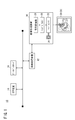
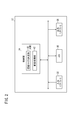
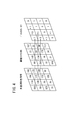
- FIG. 1 is a schematic explanatory diagram of an image forming system incorporating an image processing apparatus as a threshold value matrix creating apparatus according to the present embodiment. It is an electrical block diagram of the image processing apparatus shown in FIG. It is a schematic explanatory drawing showing the image processing flow in the signal converter shown in FIG. It is a schematic explanatory drawing of the halftone process by a systematic dither method.
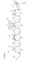
- FIG. 2 is a cross-sectional side view illustrating a configuration of the image forming apparatus illustrated in FIG. 1.
- FIG. 6 is a plan perspective view illustrating a configuration example of the line head illustrated in FIG. 5.
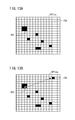
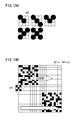
- FIG. 7A is a schematic explanatory diagram showing a part of a dot pattern.
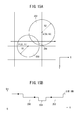
- FIG. 7B is a schematic explanatory diagram illustrating a method for calculating the first evaluation value.
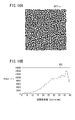
- FIG. 8A is a schematic explanatory diagram visualizing image data representing a dot pattern.
- FIG. 8B is an average value in the radial direction of a two-dimensional power spectrum obtained by performing FFT on the image data shown in FIG. 8A. It is a graph of a Dooley-Shaw function (observation distance 300 mm).
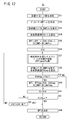
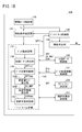
- FIG. 3 is a functional block diagram of a threshold matrix determination unit shown in FIG. 2. It is a flowchart with which it uses for operation
- FIG. 13A is an explanatory diagram showing the initial positions of dots.
- FIG. 13A is an explanatory diagram showing the initial positions of dots.
- FIG. 13B is an explanatory diagram illustrating a result of moving one dot with respect to the state illustrated in FIG. 13A. It is a detailed flowchart in step S37 of FIG.
- FIG. 15A is a schematic explanatory diagram visualizing image data simulating the formation of dots.
- FIG. 15B is a hypothetical brightness profile along the dashed arrow in FIG. 15A.
- FIG. 16A is a schematic explanatory diagram visualizing image data representing a dot pattern optimized under predetermined creation conditions.
- FIG. 16B is an average value in the radial direction of the two-dimensional power spectrum obtained by performing FFT on the image data shown in FIG. 16A.
- FIG. 6 is a functional block diagram of an image forming apparatus according to a first modification.
- FIG. 19A is a schematic explanatory diagram illustrating an example of a subpattern in which streak is likely to occur.
- FIG. 19B is a schematic explanatory diagram illustrating a calculation method of the first evaluation value according to the second modification. It is the schematic explanatory drawing which visualized the control signal used for image formation of a printing pattern.
- the threshold value matrix creating method according to the present embodiment will be described in detail with reference to the accompanying drawings by giving preferred embodiments in relation to the threshold value matrix creating device and the image forming system for carrying out the method.
- forming an image may be referred to as “printing”.
- FIG. 1 is a schematic explanatory diagram of an image forming system 10 incorporating an image processing device 12 as a threshold value matrix creating device according to the present embodiment.
- the image forming system 10 basically includes an image processing device 12, an image forming device 14, a DTP (Desktop Publishing) device 16, and a database server 18.
- the image processing device 12, the DTP device 16, and the database server 18 are electrically connected to each other by wire or wireless.
- the image processing apparatus 12 outputs input image data (device color signal or page description data) from an external apparatus to the image forming apparatus 14 side.
- the device color signal means a color signal defined by device-dependent data. For example, raster format data (TIFF, bitmap, RAW) having four (CMYK) or three (RGB) color channels. Etc.).
- raster format data TIFF, bitmap, RAW
- CMYK color modulation-based color channels
- RGB three
- the image processing apparatus 12 can create a threshold matrix Mt that is used for halftone processing according to the image forming apparatus 14.
- the image forming apparatus 14 is electrically connected to the image processing apparatus 12.
- a serial interface such as USB (Universal Serial Bus), IEEE 1394, Ethernet (registered trademark), a wireless network, or a parallel interface such as Centronics can be applied.
- the image forming apparatus 14 forms an image on the paper 20 by ejecting droplets of ink 24 from the head unit 22 while transporting a sheet as a recording medium (hereinafter referred to as paper 20) in a predetermined direction.
- paper 20 a sheet as a recording medium
- this is a so-called inkjet printer that obtains the printed material 26.
- the base material of the paper paper such as synthetic paper, cardboard, and aluminum vapor-deposited paper, resin such as vinyl chloride and PET, tarpaulin, and the like can be used.
- the image forming apparatus 14 converts an image signal input from the image processing apparatus 12 (hereinafter referred to as an input image signal) into a control signal for controlling the head unit 22. And a head driver 30 that controls the ejection of the head unit 22 based on a control signal acquired by the signal conversion unit 28.
- a droplet discharge mechanism by the head unit 22 can be adopted as a droplet discharge mechanism by the head unit 22.
- a method of ejecting droplets of ink 24 by deformation of an actuator constituted by a piezoelectric element (piezoelectric element) or the like may be applied.
- a thermal jet method may be applied in which bubbles are generated by heating the ink 24 via a heating element such as a heater and the droplets of the ink 24 are ejected with the pressure.
- the head unit 22 is not limited to a line head, and may be a multi-pass method in which an image is formed while reciprocating scanning in the width direction of the paper 20.
- the DTP device 16 can edit a material composed of characters, figures, patterns, photographs, and the like, and generates an electronic manuscript in a page description language (hereinafter referred to as PDL) by arranging the material for each page.
- PDL is a language that describes image information such as text, graphics, and other format information, position information, and color information (including density information) within a “page” that is an output unit for printing and display.
- the DTP device 16 performs rasterization processing on the electronic document in the PDL format. This rasterization processing includes data format conversion processing for converting from the PDL format to the raster format, and color conversion processing using an ICC (International Color Consortium) profile.
- ICC International Color Consortium
- the database server 18 performs data management such as a job ticket of an electronic document ⁇ for example, a JDF (Job Definition Format) file ⁇ , color sample data, a target profile, or a printing profile suitable for the combination of the image forming apparatus 14 and the paper 20. Device.
- data management such as a job ticket of an electronic document ⁇ for example, a JDF (Job Definition Format) file ⁇ , color sample data, a target profile, or a printing profile suitable for the combination of the image forming apparatus 14 and the paper 20.
- JDF Job Definition Format
- FIG. 2 is an electrical block diagram of the image processing apparatus 12 shown in FIG.
- the image processing apparatus 12 includes an input interface 32, a control unit 34, a memory 36 (recording medium), and an output interface 38.
- the memory 36 stores a program for causing it to function as a threshold matrix creation device.
- the input interface 32 receives an electrical signal from an external device. For example, device color signals and PDL data edited and created by the DTP device 16 are acquired. Further, various information such as an ICC profile stored in the database server 18 is acquired.
- the output interface 38 transmits an electrical signal to an external device.
- the image processing apparatus 12 supplies a device color signal subjected to image processing or data of a threshold value matrix Mt described later to the image forming apparatus 14 side via the output interface 38.
- the control unit 34 composed of an information processing apparatus such as a CPU includes a threshold matrix determination unit 40 and an image processing unit 42.
- the threshold matrix determination unit 40 determines a threshold matrix Mt to be used for halftone processing in the image forming apparatus 14.
- the image processing unit 42 performs image processing as necessary on the input device color signal.
- FIG. 3 is a schematic explanatory diagram showing an image processing flow in the signal conversion unit 28 shown in FIG.
- the signal conversion unit 28 basically includes a resolution conversion unit 44, a CMYK color conversion unit 46, and a halftone processing unit 48.
- the image signal (input image signal) input to the signal conversion unit 28 is multi-gradation data composed of a plurality of color channels. For example, 8-bit (256 gradations per pixel) RGB TIFF format data may be used.
- the resolution conversion unit 44 converts the resolution of the input image signal into an output resolution corresponding to the image forming apparatus 14 by using an image enlargement / reduction process that enlarges or reduces the image size.
- the first intermediate image signal obtained here has the same data definition as the input image signal, but the data size is different.
- Various known algorithms including interpolation calculation may be applied to the image enlargement / reduction processing.
- the CMYK color conversion unit 46 converts the first intermediate image signal acquired from the resolution conversion unit 44 into a device color signal (CMYK color signal) handled by the image forming apparatus 14 using a known color matching method.
- the second intermediate image signal obtained here corresponds to a multi-tone CMYK color signal.
- the halftone processing unit 48 converts the second intermediate image signal acquired from the CMYK color conversion unit 46 into a control signal (a signal used for controlling the head unit 22) for appropriately controlling the ejection of the ink 24.
- the control signal obtained here is binary data (or multi-value data) for each CMYK that controls the presence / absence (on / off) of the ejection operation of the ink 24 for each line head 84 (see FIG. 5) in time series. ).
- a halftone processing method using a systematic dither method will be described using the threshold value matrix Mt supplied from the image processing apparatus 12.
- FIG. 4 is a schematic explanatory diagram of halftone processing by the systematic dither method.
- the concept of binarization using a Bayer-type threshold matrix Mt is shown.
- each address of the multilevel CMYK color signal is associated with each matrix element of the threshold value matrix Mt.
- the magnitude relationship between the pixel value of the pixel of interest and the threshold value of the matrix element of interest is compared, and if the pixel value is larger, “1 (on)” is assigned, otherwise Assigns “0 (off)”. In this way, the number of gradations of the image signal can be converted from multi-value to binary.
- FIG. 5 is a cross-sectional side view showing the configuration of the image forming apparatus 14 shown in FIG.
- the image forming apparatus 14 is provided with a paper feed conveyance unit 54 that feeds and conveys the paper 20 on the upstream side in the conveyance direction of the paper 20.
- a processing liquid application unit 56 that applies a processing liquid to a recording surface (hereinafter referred to as an image forming surface) of the paper 20 along the conveyance direction of the paper 20, and the image.
- An image forming unit 58 that forms an image by attaching the ink 24 to the forming surface, an ink drying unit 60 that dries the ink 24 of the processing liquid layer formed on the paper 20, and an image of the processing liquid layer on the paper 20
- An image fixing unit 62 for fixing the image to the paper and a discharge unit 64 for discharging the paper 20 on which the image is fixed are provided.
- the sheet feeding / conveying unit 54 includes a stacking unit 66 provided so that the sheets 20 can be stacked, a sheet feeding unit 68 that feeds the sheets 20 stacked on the stacking unit 66 one by one, and the sheet feeding unit 68. And a transport unit 70 that transports the fed paper 20 to the treatment liquid application unit 56.
- the treatment liquid application unit 56 includes a treatment liquid application drum 72 that is rotatably provided, a treatment liquid application device 74 that applies the treatment liquid to the image forming surface of the paper 20, and a treatment liquid drying device 76 that dries the treatment liquid. And. Thus, a thin processing liquid layer is applied on the image forming surface of the paper 20.
- a first intermediate conveyance drum 78 provided rotatably is disposed. By rotating the first intermediate transport drum 78 with the paper 20 held on the surface of the first intermediate transport drum 78, the paper 20 supplied from the treatment liquid application unit 56 side is transported to the image forming unit 58 side. Is done.
- the image forming unit 58 includes an image forming drum 80 (conveying unit) that is rotatably provided, and a head unit 22 that ejects droplets of the ink 24 onto the paper 20 that is conveyed by the image forming drum 80.
- the head unit 22 includes at least Y (yellow), M (magenta), C (cyan), and K (black) line heads 84 (dot forming portions) that are basic colors.
- the line heads 84 are arranged along the circumferential direction of the image forming drum 80. As a result, images of the respective colors are sequentially formed on the treatment liquid layer applied on the image forming surface of the paper 20. Since this treatment liquid has an effect of aggregating the color material (pigment) and latex particles dispersed in the solvent of the ink 24, it is possible to prevent the color material from flowing on the paper 20.
- a second intermediate transport drum 86 that is rotatably provided is disposed. By rotating the second intermediate transport drum 86 while the paper 20 is held on the surface of the second intermediate transport drum 86, the paper 20 supplied from the image forming unit 58 side is transported to the ink drying unit 60 side.
- the ink drying unit 60 includes a rotatable ink drying drum 88, a plurality of hot air nozzles 90 for drying the treatment liquid layer of the paper 20, and a plurality of infrared heaters 92. As a result, the solvent of the ink 24 staying in the treatment liquid layer of the paper 20 is dried.
- a third intermediate conveyance drum 94 that is rotatably provided is disposed. By rotating the third intermediate transport drum 94 while the paper 20 is held on the surface of the third intermediate transport drum 94, the paper 20 supplied from the ink drying unit 60 side is transported to the image fixing unit 62 side.
- an image fixing drum 96 that is rotatably provided, a heating roller 98 that is disposed in the vicinity of the surface of the image fixing drum 96, and a surface that is in pressure contact with the surface of the image fixing drum 96.
- the fixing roller 100 is disposed.
- the sheet 20 on which the image on the image forming surface is fixed is conveyed to the discharge unit 64 provided on the downstream side of the image fixing unit 62 by the rotation of the image fixing drum 96.
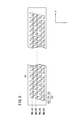
- FIG. 6 is a plan perspective view showing a structural example of the line head 84 shown in FIG.
- the line head 84 includes a plurality of ink chamber units 120 (dot forming elements) arranged in a staggered matrix.
- Each ink chamber unit 120 includes a nozzle 122, a pressure chamber 124, and a supply port 126.
- the pressure chamber 124 having a square shape in plan view is provided with an outlet to the nozzle 122 side at one of the diagonal corners, and the inlet (supply port 126) from a common channel (not shown) on the other side. Is provided.
- the longitudinal direction and the short direction of the line head 84 are defined as an arrow X direction (main direction) and an arrow Y direction (sub direction), respectively.
- the conveyance direction of the paper 20 is orthogonal to the arrow X direction and parallel to the arrow Y direction.
- the nozzles 122 in the L1th row are arranged at equal intervals along the arrow X direction at predetermined intervals (corresponding to four unit lengths).
- the nozzles in the L2 to L4 rows are also arranged in the same manner as in the L1 row.
- the arrow X direction may also be referred to as the “arrangement direction” of the nozzles 122 (ink chamber units 120).
- the nozzles 122 in the L2 row are arranged at positions shifted by one unit length in the left direction of the arrow X with reference to the positions of the nozzles 122 in the L1 row.
- Each nozzle 122 in the L3rd row is arranged at a position shifted by one unit length in the left direction of the arrow X with reference to the position of each nozzle 122 in the L2th row.
- Each nozzle 122 in the L4th row is arranged at a position shifted by one unit length in the left direction of the arrow X with reference to the position of each nozzle 122 in the L3th row. This achieves a high density of substantial intervals (projection nozzle pitch) of the nozzles 122 projected so as to be aligned along the longitudinal direction of the line head 84.
- the threshold value matrix Mt may be the same regardless of the color plate (for example, CMYK), or may be different for each color plate.
- the dot pattern DPT evaluation method Prior to the description of the method for creating the threshold matrix Mt, the dot pattern DPT evaluation method will be described.
- the evaluation is performed based on the first evaluation value EV1 quantifying the robustness against the unevenness of the stripes and the second evaluation value EV2 quantifying the noise granularity due to the dispersion of the dots.
- the first evaluation value EV1 is an evaluation value for evaluating the degree of dot overlap in one of the row direction and the column direction of the threshold value matrix Mt.
- the arrow X direction (main direction) in FIG. 6 is selected as one direction.
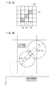
- FIG. 7A is a schematic explanatory diagram showing a part of the dot pattern DPT.
- a virtual rectangular grid that models the on / off state of dots (see FIG. 4) is prepared.
- each region of the rectangular lattice is referred to as a “cell”.
- the hatched cells (three cells in the example of FIG. 7A) correspond to on-state cells in which dots are arranged.
- virtual dots (on state) arranged on each cell corresponding to the dots formed on the paper 20 may also be simply referred to as “dots”.
- FIG. 7B is a schematic explanatory diagram illustrating a method of calculating the first evaluation value EV1.
- this figure is explanatory drawing which simulated the arrangement state of each dot based on the dot pattern DPT of FIG. 7A.
- the dot formed at the position of the target cell 130 is referred to as a first dot.
- a dot formed at the position of the adjacent cell 132 adjacent to the target cell 130 is referred to as a second dot.
- center positions (target values) where the first dots and the second dots are formed are point P and point Q, respectively. Note that the distance of the line segment PQ is Dd.
- the sizes (target values of radius) of the first dot and the second dot are R1 and R2, respectively.
- the size errors (radius variation) of the first dot and the second dot are Ers1 and Ers2, respectively.
- the landing position errors of the first dot and the second dot (hereinafter sometimes simply referred to as “position errors”) are Erp1 and Erp2, respectively.
- the landing position error means a deviation amount of the landing position with respect to the point P (or point Q), and Erp1 and Erp2 both represent components in the arrow X direction.
- the line head 84 may be capable of forming dots of a plurality of sizes, and the values of R1 and R2 may be different.
- the line head 84 may be capable of forming three or more sizes.
- the overlap amount OL between the first dot and the second dot when attention is paid to the size error of each dot is expressed by the following equation (1) by geometric consideration.
- the overlap amount OLx shown in the equation (2) is calculated for each cell in the evaluation area 134 corresponding to the target cell 130.
- the evaluation region 134 two regions (regions surrounded by a thick frame) that are highly likely to be adjacent in the arrow X direction are defined as the evaluation region 134. Note that the size and shape of the evaluation region 134 may be arbitrarily determined.
- the individual evaluation value EV (i) in the target cell 130 is expressed by the following equation (3).
- the following ⁇ means the sum for the subscript j.
- i represents the index of the target cell 130.
- j represents the index of each cell in the evaluation area 134 corresponding to the target cell 130.
- max (a, 0) is a function that returns a larger value of a and 0.
- the first evaluation value EV1 in the dot pattern DPT is expressed by the following equation (4).
- the following ⁇ means the sum for the subscript i.
- the first evaluation value EV1 generally increases as the overlap amount OLx is a positive value. That is, as the first evaluation value EV1 is larger, the amount of separation in the X direction between adjacent dots is reduced, so that the robustness against the stripe unevenness extending in the direction of the arrow Y is increased as a whole of the dot pattern DTP. On the other hand, the smaller the first evaluation value EV1, the lower the robustness against the stripe unevenness extending in the arrow Y direction as a whole of the dot pattern DTP.
- the dot size error Ers1 Ers2
- various statistics Erp can be used as the dot size error Ers1 (Ers2).
- the droplet landing position error Erp1 Erp2
- various statistics Erp can be used.
- the “statistic” is a physical quantity calculated using a statistical method, and may be, for example, an average value, a mode value, a center value, a maximum value, a minimum value, or the like. In order to obtain these statistics, it may be estimated from various characteristic values (for example, nozzle processing accuracy) associated with the statistics.
- the first evaluation value EV1 may be calculated in consideration of either the main direction (arrow X direction) or the sub direction (arrow Y direction), or may be calculated in consideration of both. In particular, it is preferably a statistic regarding a direction in which various errors (Erp, Ers) are relatively large.
- the second evaluation value EV2 is an evaluation value for evaluating noise granularity due to the dispersion of each dot.
- FIG. 8A is a schematic explanatory diagram visualizing image data representing the dot pattern DPT.
- FIG. 8B is an average value in the radial direction of a two-dimensional power spectrum obtained by performing FFT on the image data shown in FIG. 8A.
- the averaged power spectrum is simply referred to as spectrum SPC.
- the spectrum SPC has a so-called high-pass type (so-called blue noise type) spatial frequency characteristic in which the intensity level decreases from low to medium spatial frequency bands and the intensity level increases only in the high spatial frequency band.
- RMS Root Mean Square
- the pixel value (on / off state value) of each cell of the dot pattern DPT may be obtained for the pixel value (on / off state value) of each cell of the dot pattern DPT.
- the RMS value tends to be large although the visibility by the observer is good. That is, the RMS as the evaluation value may not correspond to the sensory evaluation result. Therefore, in the present embodiment, the second visual evaluation value EV2 that uses human visual response characteristics for evaluation and is further improved is used.
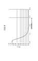
- FIG. 9 is a graph of the Dooley-Shaw function (observation distance: 300 mm), which is an example of the standard visual response characteristics of humans.
- a Dooley show function at an observation distance of 300 mm is used as the standard visual response characteristic of humans.
- the Dooley show function is a type of VTF (Visual Transfer Function) and is a representative function that imitates the standard visual response characteristics of humans. Specifically, this corresponds to the square value of the contrast ratio characteristic of luminance.
- the horizontal axis of the graph is the spatial frequency (unit: cycle / mm), and the vertical axis is the VTF value (unit is dimensionless).
- the VTF value is constant (equal to 1) in the range of 0 to 1.0 cycle / mm, and the VTF value tends to gradually decrease as the spatial frequency increases. That is, this function functions as a low-pass filter that cuts off the medium to high spatial frequency band.
- the second evaluation value EV2 is calculated by the following equation (5) when the value of the spectrum SPC is F (Ux, Uy).
- the value obtained by integrating the spectrum SPC in the entire spatial frequency band matches the square value of RMS.
- a value obtained by multiplying the spectrum SPC by VTF and integrating the new spectrum SPC in the entire spatial frequency band is an evaluation index that substantially matches human visual characteristics.
- This second evaluation value EV2 can be said to be RMS corrected with human visual response characteristics. Similar to normal RMS, the second evaluation value EV2 always takes a value of 0 or more, and the closer to 0, the better the noise granularity.
- IFFT inverse Fourier transform
- the overall evaluation value EVA for the dot pattern DPT can be calculated by combining the first evaluation value EV1 described above and the second evaluation value EV2. As an example of the overall evaluation value EVA, it is given by the following equation (6).
- EVA (EV1 ⁇ ⁇ ) / (EV2 ⁇ ⁇ ) (6)
- the value EVA is the maximum.
- ⁇ and ⁇ are theoretically determined values or empirically found values.
- the calculation formulas of the first evaluation value EV1, the second evaluation value EV2, and the overall evaluation value EVA can be variously changed according to the target level (allowable range) and the evaluation function for determining the dot pattern DPT. Not too long.
- FIG. 10 is a functional block diagram of the threshold matrix determination unit 40 shown in FIG.
- the threshold value matrix determination unit 40 includes a gradation level designation unit 140 that sequentially designates gradation levels that have not been set (designated level lv described later), and gradation levels designated by the gradation level designation unit 140.
- a constraint condition setting unit 142 that sets a constraint condition in the dot pattern DPT, a dot pattern determination unit 144 that determines a dot pattern DPTfix according to the specified gradation level, and a dot determined by the dot pattern determination unit 144
- a dot pattern storage unit 146 that stores a pattern DPTfix, a threshold value determination unit 148 that determines a threshold matrix Mt according to the arrangement of dots in the dot pattern DPTfix stored by the dot pattern storage unit 146, and the dot pattern determination unit 144
- Various intermediate data generated in the calculation process It includes an intermediate data storage unit 150 for storing appropriate statistics Erp of position error in which a plurality of dots are formed, and the dot formation information storage unit 151 for storing the dot formation information
- the dot pattern determination unit 144 includes a dot number determination unit 152, an initial pattern generation unit 154, a dot position movement unit 156 (dot pattern generation unit), an evaluation value map calculation unit 158, and an overall evaluation value calculation unit 160. (Evaluation value calculation unit) and an update availability determination unit 162.
- the number of dots to be arranged on the rectangular grid of the threshold matrix Mt is determined according to the gradation level, and the dot arrangement order is optimized by sequentially repeating the dot arrangement and its evaluation. Then, based on the optimized dot arrangement order, the threshold value in each matrix element of the threshold value matrix Mt is determined.
- the gradation level designation unit 140 designates one gradation level that has not yet been set (step S1).
- the designated gradation level may be referred to as “designated level lv”. This designation may be in accordance with the order of gradation levels (ascending order or descending order), or may be sequentially designated at random.
- the constraint condition setting unit 142 sets a constraint condition in the dot pattern DPT (including DPTfix, DPTini, and DPTtmp described later) at the specified level lv (step S2).
- the constraint condition is a condition that restricts the arrangement of dots at each gradation level in order to determine the threshold value in each matrix element of the threshold value matrix Mt without contradiction. Specifically, it is necessary to inherit the dot arrangement and order already determined at the gradation level lower than the designated level lv even at the designated level lv. In addition, it is necessary to select a dot position from among dot arrangements already determined at a gradation level higher than the designated level lv.
- the dot pattern DPTfix of each gradation level that has already been determined may be read and referred to so as to satisfy all such constraints.
- the dot pattern determination unit 144 determines a dot pattern DPTfix [lv] corresponding to the designated level lv (step S3). A specific determination method will be described later.
- the dot pattern storage unit 146 acquires and temporarily stores the dot pattern DPTfix [lv] determined by the dot pattern determination unit 144.
- the gradation level designation unit 140 determines whether or not the dot pattern DPTfix [lv] has been established at all gradation levels (step S4). If it is determined that it has not been confirmed, the process returns to step S1, and thereafter, steps S1 to S3 are repeated until it is confirmed.
- the threshold matrix determination unit 40 determines the threshold matrix Mt.
- a method is used in which a dot pattern DPT in which the arrangement of dots is variously changed and an evaluation using evaluation values (an overall evaluation value EVA and an evaluation value map EV_MAP described later) are sequentially repeated.
- various search algorithms such as a structural algorithm and a sequential improvement algorithm can be used as an optimization problem for determining the dot pattern DPT.
- VC method a method for optimizing the dot pattern DPT by the void-and-cluster method
- the dot number determination unit 152 determines the number of dots to be arranged in the cell according to the designated level lv (step S31). For example, it is associated in advance with the value of the designated level lv or the size (total number of cells) of the threshold matrix Mt.
- the initial pattern creation unit 154 creates a dot pattern DPTini as initial data (step S32).
- the initial pattern creation unit 154 obtains the dot pattern DPTini illustrated in FIG. 13A by arranging the determined number of dots on the cell.
- the dot arrangement may be determined randomly based on, for example, a random value generated using a pseudo-random number generation algorithm.
- a pseudo-random number generation algorithm various algorithms such as Mersenne Twister, SFMT (SIMD-oriented Fast Mersenne Twister), and Xorshift method may be used.
- the evaluation value map calculation unit 158 calculates an evaluation value map EV_MAPini as initial data from the dot pattern DPTini created in step S32 (step S33).
- the evaluation value map EV_MAPini includes each evaluation value calculated for each cell based on a predetermined evaluation function. The larger the evaluation value is, the better the performance is designed. For example, the evaluation value map EV_MAPini is given as a set of evaluation values EV (i) for each cell ⁇ see Equation (3) and FIG. 7B ⁇ .
- the dot formation information is read from the dot formation information storage unit 151 in advance.
- dot formation information is information related to dot formation, and includes position error statistic Erp, size error statistic Ers, and output resolution (arrow X direction / arrow Y direction). Also good. Further, the dot formation information storage unit 151 may store dot formation information corresponding to the type of paper 20 (or the type of ink 24).
- the overall evaluation value calculation unit 160 calculates an overall evaluation value EVA as initial data from the evaluation value map EV_MAPini created in step S33 (step S34).
- the evaluation value map EV_MAPini is an individual evaluation value in each cell, whereas the overall evaluation value EVA is an evaluation value for the entire arrangement of dots.
- Various methods can be used for calculating the overall evaluation value EVA. For example, the overall evaluation value EVA is given by the above equation (6).
- the update availability determination unit 162 assigns 0 to an integer variable K, and initializes K (step S36).
- K is a counter representing the number of times of determination as to whether or not the dot pattern DPT needs to be updated.
- the dot position moving unit 156 acquires the dot pattern DPTtmp by moving the dot position so as to satisfy the constraint condition while following a predetermined evaluation criterion based on the first evaluation value EV1 and the second evaluation value EV2. (Step S37). This acquisition method will be described in more detail with reference to the flowchart of FIG.
- the evaluation value map EV_MAP for determining dot movement is corrected according to the human visual response characteristics. Specifically, the evaluation value in a cell (dense dots) that is easily visible is maximized, and the evaluation value in a cell in which the dots are off is minimized. Thereby, the success probability that the dots move is improved, and the processing operation can be speeded up.
- the dot position moving unit 156 creates image data simulating the formation of dots (step S371).
- this image data is referred to as a simulated image SIM_IMG.
- FIG. 15A is a diagram simulating the arrangement state of each dot based on the dot pattern DPT in FIG. 7A. For example, it is assumed that the first dot formation region 200 and the second dot formation region 202 each have a uniform color. At this time, as shown in FIG. 15B, the lightness (L * ) profile along the broken line arrow is estimated.
- This graph is a cross-sectional profile of a simulated image SIM_IMG in which signal values are defined by brightness.
- the sample interval of the simulated image SIM_IMG is smaller than the sample interval of the threshold matrix Mt, for example, the color change in the overlapping region 204 between the formation region 200 and the formation region 202 can be accurately simulated.
- the dot position moving unit 156 applies a visual filter to the simulated image SIM_IMG (step S372).
- the visual filter for example, the inverse transform characteristic of VTF shown in FIG. 9 may be used.
- the calculated value at the position corresponding to each cell is temporarily stored in the intermediate data storage unit 150 as the visual correction map VF_MAP. Note that it is preferable to use a visual filter corresponding to the sample interval of the simulated image SIM_IMG in order to accurately correspond to the human visual response characteristics.
- the dot position moving unit 156 corrects the evaluation value map EV_MAP (step S373). Specifically, an operation for multiplying the current evaluation value map EV_MAP by the visual correction map VF_MAP calculated in step S372 is executed for each cell.
- the obtained map is referred to as a corrected map EVC_MAP.
- the dot position moving unit 156 validates all replacement combinations (step S374).
- the dot position moving unit 156 determines a pair of cells (cell pair) that maximizes the difference value of the corrected map EVC_MAP (step S375). That is, the cell having the maximum value of the corrected map EVC_MAP and the cell having the minimum value are extracted one by one.
- the dot position moving unit 156 determines whether or not the current dot pattern DPT changes by exchanging the cell pair selected in step S375 (step S376). Specifically, when the number of dots (ON state) in the selected cell pair is 0 or 2, the dot pattern DPT does not change. Further, when there is one dot (ON state) in the selected cell pair, the dot pattern DPT changes.
- step S375 If it is determined that there is no change, the exchange combination by the cell pair selected in step S375 is excluded (step S378), and another cell pair having the next largest difference value of the corrected map EVC_MAP is sequentially selected (step S378). S375).
- the dot position moving unit 156 further determines whether or not the constraint condition at the designated level lv is satisfied (step S377). If it is determined that the constraint condition is not satisfied, the exchange combination by the cell pair determined in step S375 is excluded (step S378), and another cell pair having the next largest difference value of the corrected map EVC_MAP is sequentially selected. (Step S375).
- the dot position moving unit 156 exchanges the on / off state of the cell pair with respect to the dot pattern DPT, and acquires a new dot pattern DPTtmp (step S379).
- the corrected map EVC_MAP in the first cell 206 is the maximum and the corrected map EVC_MAP in the second cell 208 is the minimum.
- the ON / OFF state of the first cell 206 and the second cell 208 is reversed, so that the dot existing at the position of the first cell 206 moves to the position of the second cell 208. .
- the dot position moving unit 156 acquires the dot pattern DPTtmp by moving the dot position so as to satisfy the constraint conditions (step S37).
- the evaluation value map calculation unit 158 calculates the evaluation value map EV_MAPtmp from the dot pattern DPTtmp (step S38). Then, the overall evaluation value calculation unit 160 calculates the overall evaluation value EVAtmp from the evaluation value map EV_MAPtmp (step S38). These calculation methods are the same as the calculation methods in steps S32 and S33.
- the update availability determination unit 162 compares the magnitude relationship between the overall evaluation value EVAtmp of the dot pattern DPTtmp and the overall evaluation value EVA that is the current maximum value (step S39). If EVAtmp> EVA is not satisfied (that is, EVAtmp ⁇ EVA), the process proceeds to the next step S41 without performing step S40.
- the intermediate data storage unit 150 overwrites and updates the dot pattern DPTtmp obtained in step S37 with respect to the currently stored dot pattern DPT (step S40). Further, the intermediate data storage unit 150 overwrites and updates the evaluation value EVAtmp obtained in step S38 with respect to the currently stored overall evaluation value EVA (step S40). Further, the intermediate data storage unit 150 overwrites and updates the evaluation value map EV_MAPtmp obtained in step S38 with respect to the currently stored evaluation value map EV_MAP (step S40). Thereafter, the process proceeds to the next step S41.
- the update availability determination unit 162 adds 1 to the current value of K (step S41).
- the update availability determination unit 162 tentatively determines the current dot pattern DPT.
- the dot pattern DPT is determined (step S44).
- the dot pattern determination unit 144 determines the dot pattern DPT updated last as the dot pattern DPTfix [lv] (see step S3 in FIG. 11).
- FIG. 16A is a schematic explanatory diagram visualizing image data representing a dot pattern DPTfix optimized under predetermined creation conditions.
- FIG. 16B is an average value in the radial direction of the two-dimensional power spectrum obtained by performing FFT on the image data shown in FIG. 16A.
- the dot pattern DPTfix shown in FIG. 16A has a larger proportion of dots connected in one direction (row direction) than the dot pattern DPT in FIG. 7A. Thereby, the robustness with respect to the stripe unevenness extended in a conveyance direction (arrow Y direction) improves.
- either the row direction or the column direction of the threshold value matrix Mt is based on the statistical amount Erp of the position error (Erp1, Erp2) or the statistical amount Ers of the size error (Ers1, Ers2) at which a plurality of dots are formed. Since the first evaluation value EV1 in which the degree of dot overlap in one direction is quantified is calculated, the degree of influence on the image due to the dot formation variation can be predicted statistically and quantitatively. Then, by appropriately determining the threshold value matrix Mt based on the first evaluation value EV1, the robustness against the unevenness of muscle extending in the one direction is increased.
- This embodiment may be configured as in the following modifications 1 to 3.
- the same components as those of the image processing apparatus 12 and the image forming apparatus 14 (see FIGS. 1 to 16B) according to the present embodiment are denoted by the same reference numerals, and detailed description thereof is omitted.
- the threshold matrix determination unit 40 is provided in the image processing apparatus 12 (see FIG. 2), but may be integrated into the image forming apparatus 220.
- FIG. 17 is a functional block diagram of the image forming apparatus 220 according to the first modification.
- the image forming apparatus 220 further includes a threshold matrix determination unit 40A having the same function as the threshold matrix determination unit 40 (see FIGS. 2 and 10). .
- a threshold matrix determination unit 40A having the same function as the threshold matrix determination unit 40 (see FIGS. 2 and 10).
- overall evaluation value calculation section 160 calculates first evaluation value EV1 by geometric calculation, but it may be calculated using another method (for example, pattern matching method).
- FIG. 18 is a functional block diagram of the threshold matrix determination unit 40B according to the second modification.
- the threshold matrix determination unit 40B includes, in addition to the units shown in FIG. 10, a sub pattern determination unit 230 that determines a plurality of partial dot patterns (hereinafter referred to as sub patterns SPT) having a size smaller than the threshold matrix Mt, A robust score determination unit 232 that quantifies the robustness of the degree of dot overlap in each sub-pattern SPT determined by the pattern determination unit 230 and determines each score is further provided.
- evaluation value map calculation unit 158B (or overall evaluation value calculation unit 160B) calculates evaluation value map EV_MAP or the like (or overall evaluation value EVA or the like) using the calculation method in the second modification.
- Steps S33, S34, and S38 (see FIG. 12) different from the present embodiment will be described with reference to FIGS. 19A and 19B.
- step S33 prior to calculation of the evaluation value map EV_MAPini (EV_MAPtmp), the sub-pattern determining unit 230 determines a sub-pattern SPT used for pattern matching described later.
- the robustness score determination unit 232 then quantifies the robustness of the degree of dot overlap in each subpattern SPT determined by the subpattern determination unit 230.
- FIG. 19A is a schematic explanatory diagram illustrating an example of a sub-pattern SPT in which streaks are likely to occur.
- a sub-pattern SPT having three cells in both the row direction and the column direction is shown.
- Each sub-pattern SPT is characterized in that the dots are not adjacent to each other in the vertical direction but are adjacent in the oblique direction.
- the position errors Erp1 and Erp2 gradually increase, the possibility of the occurrence of uneven stripes extending in one direction (row direction) increases rapidly. In this way, the sub-pattern SPT that tends to cause unevenness is selectively extracted.
- the output characteristics of the image forming apparatus 14 (output resolution, dot size R1, R2, position error Erp1, Erp2 statistic Erp, size error Ers1, Ers2 statistic Ers Various changes may be made.
- FIG. 19B is a schematic explanatory diagram illustrating a calculation method of the first evaluation value EV1 according to the second modification.
- the partial pattern of the dot pattern DPTini is compared with the sub-pattern SPT determined in advance by the sub-pattern determining unit 230.
- the partial pattern refers to a part of dot patterns in the dot pattern DPTini (or DPTtmp).
- pattern matching is performed while sequentially changing the position of the target cell (the central cell of the partial pattern). As shown in this example, raster scanning may be performed in the horizontal direction.
- the evaluation value map calculation unit 158B adds a score corresponding to the sub pattern SPT. After collation with all the sub patterns SPT is completed, the evaluation value map calculation unit 158B calculates the total of the scores as the individual evaluation value EV (i) in the target cell. Then, the evaluation value map EV_MAP is obtained by calculating the individual evaluation value EV1 (i) while sequentially changing the target cell.
- step S34 (or S38), overall evaluation value calculation unit 160B calculates overall evaluation value EVA based on evaluation value map EV_MAP calculated by evaluation value map calculation unit 158B.
- the first evaluation value EV1 can be calculated by a relatively simple method with a small amount of calculation.
- the statistics Erp and Ers are estimated from various characteristic values (such as nozzle forming accuracy), but may be measured based on actual printing results. For example, various statistics can be easily acquired by analyzing an image after printing a specific print pattern 240.
- FIG. 20 is a schematic explanatory diagram visualizing a control signal used for ejection formation of the print pattern 240.
- a plurality of cells described in the signal area 242 represent control signals in the respective nozzles 122 (see FIG. 6) in time series. Specifically, a black cell represents an on state, and a white cell represents an off state. That is, on the paper 20, each dot is formed at a two-dimensional position corresponding to the black cell.
- a plurality of line images 244 extending in the arrow Y direction (conveyance direction) are regularly formed.
- One nozzle is selected from the plurality of nozzles 122, and one line image 244 extending in the arrow Y direction (conveyance direction) is formed by the nozzle alone. Since the line images 244 are formed for each nozzle 122, the total number of line images 244 matches the total number of nozzles 122 provided in the line head 84 (see FIG. 6).
- the width of the line image 244 corresponds to 1 cell (dot), and the length corresponds to 10 cells (dot).
- the print pattern 240 is formed on the paper 20 by supplying a control signal representing the print pattern 240 to the head driver 30 (see FIG. 1) and performing appropriate print control. Thereafter, after reading the print pattern 240 with an image reading device (not shown) (so-called scanner), various analysis methods are applied to the read image data to measure various statistics. Specific examples are shown below.
- alignment processing of read image data and control signal data shown in FIG. 20 is performed using a known pattern matching method. It is necessary to enlarge or reduce the size of the control signal data so as to match the input resolution of the image reading apparatus.
- each of the line images 244 is detected from the read image data, and a positional deviation amount in the read image data with respect to a position (ideal position) in the control signal data is measured.
- the actual misregistration amount can be calculated by the product of the number of pixels in the read image data and the unit pixel size.
- the dot position error (statistic Erp) at each nozzle 122 can be measured.
- each detected line image 244 is measured.
- Each actual width and length can be calculated by the product of the number of pixels in the read image data and the unit pixel size. In this way, the dot size error (statistics Ers) at each nozzle 122 can be measured.
- the threshold matrix Mt is stored in the image processing device 12 (for example, the dot formation information storage unit 151 in FIG. 10) in order to create the threshold matrix Mt. This makes it possible to refer to dot formation information when creating the threshold matrix Mt.
- the width or length of the line image 244 may be changed as appropriate according to the type. For example, by making the line image 244 sufficiently long, it becomes difficult to be affected by errors due to dust adhesion or the like when reading the image. If the line head 84 can form dots of a plurality of sizes, the statistics Erp and Ers may be measured according to the dot size.
- the arrangement of the line image 244 may be appropriately changed so that landing interference between the droplets of the ink 24 does not occur.
- the interval between the line images 244 may be larger than usual. The same effect can be obtained even when a sufficient time difference is provided at the point of time when the droplets of the ink 24 land on adjacent dots.
- the position error statistic Erp and the size error statistic Ers can be easily measured.
- CMYK four color plates
- the design can be changed to any color plate type and plate number without being limited thereto.
- a standard ink of CMYK may be combined with an optional ink such as light colors such as LC and LM and W (white).
- the paper 20 is conveyed by the rotation of the image forming drum 80, but at least one of the head unit 22 and the paper 20 may be conveyed. This is because the present invention can be applied as long as both are relatively moved.
- the size in the row direction or the column direction of the threshold matrix Mt or the number of threshold levels is not limited to the present embodiment, and may be changed as appropriate.
Landscapes
- Engineering & Computer Science (AREA)
- Multimedia (AREA)
- Signal Processing (AREA)
- Facsimile Image Signal Circuits (AREA)
- Image Processing (AREA)
Abstract
本発明は、閾値マトリクス作成装置、方法、プログラム及び画像形成装置に関する。複数のドットが形成される位置誤差(Erp1、Erp2)の統計量(Erp)又はサイズ誤差(Ers1、Ers2)の統計量(Ers)に基づいて、閾値マトリクス(Mt)の行方向及び列方向のいずれか一方向におけるドットの重なり程度を定量化した評価値(EV1)を算出する。そして、評価値(EV1)に基づいて閾値マトリクス(Mt)を決定する。
Description
この発明は、ハーフトーン処理に供される閾値マトリクスを作成する閾値マトリクス作成装置、方法、プログラム及び画像形成装置に関する。
近時、インクジェット技術の飛躍的進歩に伴い、インクジェット方式の画像形成装置による高速・高画質を両立したカラー大判印刷が可能になりつつある。この装置は、特にサイン・ディスプレイ用途において幅広い分野で用いられ、例えば、店頭POP(Point Of Purchase)や壁面ポスター、屋外広告・看板等の印刷にも適用可能である。インクジェット方式では、記録媒体上に複数種のインク(例えばCMYKインク)の液滴を吐出して多数のドットを形成することで、印刷物を得ることができる。
そして、前記インクジェット方式のうち、配列方向(以下、主方向という場合がある。)に沿って配列された複数のノズルを備える記録ヘッド(以下、ラインヘッドという。)を使用するシングルパス方式が特に注目されている。なぜならば、記録媒体又はラインヘッドを1回だけ所定方向に移動させることで記録媒体上の画像を完成可能であり、サイン・ディスプレイ用途で要求される各種仕様(高速化・低電力化・高画質化)をすべて両立し得るからである。一方、シングルパス方式では、何らかの変動要因により、各ノズルからのインク滴の着弾位置が目標位置から主方向にずれる結果、所定方向(例えば、記録媒体の搬送方向)に延在する濃い又は淡い筋むら(以下、単に筋むらという。)が発生し易いという課題があった。
この課題に対して、シングルパス方式であっても、前記筋むらの発生程度を低減可能なラインヘッド等の改良技術が種々提案されている。
特開2007-44967号公報には、斜めの列方向に沿って複数のノズルが規則的な配列間隔でマトリクス状に多数配置された構造を有するラインヘッドが開示されている。これにより、複数のタイミングで各ドットを順次形成させて画像を完成することで、主方向での繰り返し周期を短縮可能であり、筋むらの発生を抑制できる。
このほか、各ノズルからインク滴を吐出制御するための制御信号を補正することで、筋むらの発生程度を低減する方法も種々提案されている。
特開2006-159810号公報には、各ノズルの飛行曲がり量から主方向に隣接するドットの隙間を算出し、該隙間の大小に応じてハーフトーン処理に供される閾値マトリクス(ディザマトリクス)を補正する装置及び方法が開示されている。
特開2001-113805号公報には、インク滴の着弾位置のずれ量を検出可能なテストチャートを印刷した後、その画像を読取処理部で読み取り、読取結果に基づいて画像信号を補正する装置及び方法が開示されている。
ところで、各ノズルからのインク滴の着弾位置がずれる変動要因には、各ノズルの成形加工精度による恒久的な要因もあれば、ノズル付近での塵埃の付着等による一時的な要因もある。後者は、ノズル状態を回復させるべく、吸引等によるヘッドクリーニング処理を施すことで、インク滴の飛行曲がり量を低減できる場合がある。
しかし、上記した一時的な変動要因により、飛行曲がりの方向が突発的に反転する場合、特開2006-159810号公報及び特開2001-113805号公報に開示された装置等では、期待された補正の効果が得られないどころか、筋むらの発生が却って増長される懸念もある。すなわち、筋むらに対する頑健性(ロバストネス)が低いと言える。
本発明は上記した問題を解決するためになされたもので、筋むらに対する頑健性が高い閾値マトリクスを作成する閾値マトリクス作成装置、方法、プログラム及び画像形成装置を提供することを目的とする。
本発明は、複数のドットを形成可能である画像形成装置に応じたハーフトーン処理のための閾値マトリクスを作成する閾値マトリクス作成装置に関する。
前記閾値マトリクスの行方向及び列方向のいずれか一方向におけるドットの重なり程度を定量化した第1評価値に基づいて前記閾値マトリクスを決定する閾値マトリクス決定部を有し、前記第1評価値は、前記複数のドットが形成される位置誤差の統計量又はサイズ誤差の統計量に基づいて算出された評価値であることを特徴とする。
このように、複数のドットが形成される位置誤差の統計量又はサイズ誤差の統計量に基づいて、閾値マトリクスの行方向及び列方向のいずれか一方向におけるドットの重なり程度を定量化した第1評価値を算出するようにしたので、ドットの形成ばらつきに起因する画像への影響度を統計的且つ定量的に予測可能である。そして、前記第1評価値に基づいて閾値マトリクスを適切に決定することで、前記一方向に延在する筋むらに対する頑健性が高くなる。
また、前記閾値マトリクス決定部は、前記画像形成装置に入力される画像信号の複数の階調レベルに応じた複数のドットパターンを前記第1評価値に基づいて作成するドットパターン作成部と、前記ドットパターン作成部により作成された前記複数のドットパターンにおけるドットの配列に従って前記閾値マトリクスを決定する閾値決定部とを備えることが好ましい。
さらに、前記閾値マトリクス決定部は、幾何学的計算により得られた前記重なり程度から前記第1評価値を算出する評価値算出部をさらに備えることが好ましい。
また、前記閾値マトリクス決定部は、各前記ドットパターンよりも小さいサイズのサブパターンを複数決定するサブパターン決定部と、各前記ドットパターンの部分パターンと、前記サブパターン決定部により決定された各前記サブパターンとの一致度に基づいて前記第1評価値を算出する評価値算出部とをさらに備えることが好ましい。
さらに、前記閾値マトリクス決定部は、前記位置誤差の統計量又は前記サイズ誤差の統計量に基づいて各前記サブパターンにおける前記重なり程度の頑健性を定量化し、各得点を決定する頑健性得点決定部をさらに備え、前記評価値算出部は、前記頑健性得点決定部により決定された各前記サブパターンに応じた前記得点に基づいて前記第1評価値を算出することが好ましい。
さらに、前記評価値算出部は、各前記ドットパターンのノイズ粒状性を定量化した第2評価値をさらに算出し、前記ドットパターン作成部は、前記評価値算出部により算出された前記第1評価値及び前記第2評価値に基づいて前記複数のドットパターンを作成することが好ましい。
さらに、前記第2評価値は、人間の視覚応答特性関数により補正されたRMS粒状度であることが好ましい。
さらに、前記統計量には、標準偏差、平均値、最頻値、中心値、最大値及び最小値のうち少なくとも1つが含まれることが好ましい。
さらに、前記第1評価値は、前記行方向及び前記列方向のうち誤差が大きい方の前記位置誤差の統計量に基づいて算出された前記一方向における評価値であることが好ましい。
本発明に係る閾値マトリクス作成方法は、複数のドットを形成可能である画像形成装置に応じたハーフトーン処理のための閾値マトリクスを作成する方法であって、前記複数のドットが形成される位置誤差の統計量又はサイズ誤差の統計量に基づいて、前記閾値マトリクスの行方向及び列方向のいずれか一方向におけるドットの重なり程度を定量化した評価値を算出する算出ステップと、算出された前記評価値に基づいて前記閾値マトリクスを決定する決定ステップとを備えることを特徴とする。
また、前記画像形成装置が、配列方向に沿って配列された複数のドット形成素子を備え、該複数のドット形成素子を用いて複数のドットを記録媒体上に形成するドット形成部と、前記ドット形成部及び前記記録媒体のうち少なくとも一方を所定の搬送方向に搬送することで前記ドット形成部と前記記録媒体とを相対移動させる搬送部とを有する場合、前記複数のドット形成素子のうち1つのドット形成素子を用いて、前記搬送方向に延在する線画像を形成する画像形成ステップと、形成された前記線画像から、前記1つのドット形成素子における前記位置誤差の統計量又は前記サイズ誤差の統計量を計測する計測ステップとをさらに備えることが好ましい。
本発明に係るプログラムは、複数のドットを形成可能である画像形成装置に応じたハーフトーン処理のための閾値マトリクスを作成するプログラムであって、コンピュータを、前記閾値マトリクスの行方向及び列方向のいずれか一方向におけるドットの重なり程度を定量化した評価値に基づいて前記閾値マトリクスを決定する閾値マトリクス決定部として機能させ、前記評価値は、前記複数のドットが形成される位置誤差の統計量又はサイズ誤差の統計量に基づいて算出された評価値であることを特徴とする。
本発明に係る画像形成装置は、配列方向に沿って配列された複数のドット形成素子を備え、該複数のドット形成素子を用いて複数のドットを記録媒体上に形成するドット形成部と、前記ドット形成部及び前記記録媒体のうち少なくとも一方を所定の搬送方向に搬送することで前記ドット形成部と前記記録媒体とを相対移動させる搬送部と、前記搬送部による前記相対移動の下、ハーフトーン処理に供される閾値マトリクスの行方向及び列方向のいずれか一方向におけるドットの重なり程度を定量化した評価値に基づいて前記閾値マトリクスを決定する閾値マトリクス決定部と、前記閾値マトリクス決定部により決定された前記閾値マトリクスを用いた前記ハーフトーン処理により、入力された画像信号を、前記ドット形成部を制御する制御信号に変換する信号変換部とを有し、前記評価値は、前記複数のドットが形成される位置誤差の統計量又はサイズ誤差の統計量に基づいて算出された評価値であることを特徴とする。
本発明に係る閾値マトリクス作成装置、方法、プログラム及び画像形成装置によれば、複数のドットが形成される位置誤差の統計量又はサイズ誤差の統計量に基づいて、閾値マトリクスの行方向及び列方向のいずれか一方向におけるドットの重なり程度を定量化した評価値を算出するようにしたので、ドットの形成ばらつきに起因する画像への影響度を統計的且つ定量的に予測可能である。そして、前記評価値に基づいて閾値マトリクスを適切に決定することで、前記一方向に延在する筋むらに対する頑健性が高くなる。
以下、本実施の形態に係る閾値マトリクス作成方法について、それを実施する閾値マトリクス作成装置及び画像形成システムとの関係において好適な実施形態を挙げ、添付の図面を参照しながら詳細に説明する。本明細書において、画像を形成することを「印刷」という場合がある。
図1は、本実施の形態に係る閾値マトリクス作成装置としての画像処理装置12を組み込んだ画像形成システム10の概略説明図である。画像形成システム10は、画像処理装置12と、画像形成装置14と、DTP(Desktop Publishing)装置16と、データベースサーバ18とを基本的に備える。画像処理装置12、DTP装置16及びデータベースサーバ18は、有線又は無線によって相互に電気的に接続されている。
画像処理装置12は、外部装置からの入力画像データ(デバイス色信号又はページ記述データ)を画像形成装置14側に出力する。ここで、デバイス色信号とは、デバイス依存データで定義された色信号を意味し、例えば、4色(CMYK)或いは3色(RGB)のカラーチャンネルを有するラスタ形式データ(TIFF、ビットマップ、RAW等)である。また、画像形成装置14に供給されるデバイス色信号として、任意のヘッダを付加した独自のフォーマットデータを用いてもよい。また、画像処理装置12は、画像形成装置14に応じたハーフトーン処理に供される閾値マトリクスMtを作成可能である。
画像形成装置14は、画像処理装置12に電気的に接続されている。この接続には、例えば、USB(Universal Serial Bus)、IEEE1394、イーサネット(登録商標)、無線ネットワーク等のシリアルインターフェイスや、セントロニクス等のパラレルインターフェイスを適用することができる。
画像形成装置14は、記録媒体としての枚葉紙(以下、用紙20という。)を所定方向に搬送させながら、ヘッドユニット22からインク24の液滴を吐出させることで用紙20上に画像を形成し、印刷物26を取得する、いわゆるインクジェットプリンタである。用紙20の基材には、合成紙・厚紙・アルミ蒸着紙等の紙類、塩化ビニル・PET等の樹脂やターポリン等を用いることができる。
画像形成装置14は、ヘッドユニット22の他、画像処理装置12から入力された画像信号(以下、入力画像信号という。)を、ヘッドユニット22を制御するための制御信号に変換する信号変換部28と、該信号変換部28により取得された制御信号に基づいてヘッドユニット22を吐出制御するヘッドドライバ30とを備えている。
なお、ヘッドユニット22による液滴の吐出機構として、種々の方式を採り得る。例えば、ピエゾ素子(圧電素子)等で構成されるアクチュエータの変形によってインク24の液滴を吐出する方式を適用してもよい。また、ヒータ等の発熱体を介してインク24を加熱することで気泡を発生させ、その圧力でインク24の液滴を吐出するサーマルジェット方式を適用してもよい。また、ヘッドユニット22は、ラインヘッドに限定されることなく、用紙20の幅方向に往復走査しながら画像を形成させるマルチパス方式であってもよい。
DTP装置16は、文字、図形、絵柄や写真等から構成される素材を編集可能であり、該素材をページ毎に配置することで、ページ記述言語(以下、PDLという。)による電子原稿を生成する。ここで、PDLとは、印刷や表示等の出力単位である「ページ」内で文字、図形等の書式情報、位置情報、色情報(濃度情報を含む)等の画像情報を記述する言語である。DTP装置16は、PDL形式の電子原稿に対してラスタライズ処理を施す。このラスタライズ処理には、PDL形式からラスタ形式に変換するデータ形式変換処理と、ICC(International Color Consortium)プロファイルを用いた色変換処理とが含まれる。
データベースサーバ18は、電子原稿のジョブチケット{例えば、JDF(Job Definition Format)ファイル}、色見本データ、ターゲットプロファイル、又は画像形成装置14及び用紙20の組合せに適した印刷プロファイル等のデータ管理を行う装置である。
図2は、図1に示す画像処理装置12の電気的なブロック図である。
画像処理装置12は、入力インターフェース32と、制御部34と、メモリ36(記録媒体)と、出力インターフェース38とを備えている。メモリ36には、閾値マトリクス作成装置として機能させるためのプログラムが格納されている。
入力インターフェース32は、外部装置からの電気信号を受信する。例えば、DTP装置16で編集・作成されたデバイス色信号やPDLデータを取得する。また、データベースサーバ18で記憶されたICCプロファイル等の各種情報を取得する。出力インターフェース38は、外部装置に電気信号を送信する。例えば、画像処理装置12は、出力インターフェース38を介して、画像処理されたデバイス色信号又は後述する閾値マトリクスMtのデータを画像形成装置14側に供給する。
CPU等の情報処理装置で構成される制御部34は、閾値マトリクス決定部40と、画像処理部42とを備えている。閾値マトリクス決定部40は、画像形成装置14でのハーフトーン処理に供される閾値マトリクスMtを決定する。画像処理部42は、入力されたデバイス色信号に対して必要に応じた画像処理を施す。
図3は、図1に示す信号変換部28における画像処理流れを表す概略説明図である。信号変換部28は、解像度変換部44と、CMYK色変換部46と、ハーフトーン処理部48とを基本的に備える。
信号変換部28に入力される画像信号(入力画像信号)は、複数のカラーチャンネルからなる多階調データである。例えば、8ビット(1画素当り256階調)RGBのTIFF形式データであってもよい。
解像度変換部44は、画像サイズを拡大又は縮小する画像拡縮処理を用いて、入力画像信号の解像度を、画像形成装置14に応じた出力解像度に変換する。ここで得られる第1中間画像信号は、入力画像信号とデータ定義は同一であるが、データサイズが異なっている。この画像拡縮処理には、補間演算を含む公知のアルゴリズムを種々適用してもよい。
CMYK色変換部46は、公知のカラーマッチング手法を用いて、解像度変換部44から取得した第1中間画像信号を、画像形成装置14で取り扱うデバイス色信号(CMYK色信号)に変換する。ここで得られる第2中間画像信号は、多階調のCMYK色信号に相当する。
ハーフトーン処理部48は、CMYK色変換部46から取得した第2中間画像信号を、インク24を適切に吐出制御するための制御信号(ヘッドユニット22の制御に供される信号)に変換する。ここで得られる制御信号は、各ラインヘッド84(図5参照)に対してインク24の吐出動作の有無(オン・オフ)を時系列的に制御するCMYK毎の2値データ(あるいは多値データ)である。本実施の形態では、画像処理装置12から供給された閾値マトリクスMtを用いて、組織的ディザ法によるハーフトーン処理方法について説明する。
図4は、組織的ディザ法によるハーフトーン処理の概略説明図である。一例として、ベイヤー型の閾値マトリクスMtを用いた2値化の概念を示す。先ず、多値CMYK色信号の各アドレスと、閾値マトリクスMtの各行列要素とを対応付ける。そして、着目する画素での画素値と、着目する行列要素での閾値との大小関係をそれぞれ比較し、画素値の方が大きい場合には「1(オン)」を割り当て、それ以外の場合には「0(オフ)」を割り当てる。このようにして、画像信号の階調数を多値から2値に変換することができる。
図5は、図1に示す画像形成装置14の構成を表す断面側面図である。
画像形成装置14には、用紙20の搬送方向上流側に、用紙20を給紙搬送する給紙搬送部54が設けられている。この給紙搬送部54の下流側には、用紙20の搬送方向に沿って、用紙20の記録面(以下、画像形成面という。)に処理液を塗布する処理液塗布部56と、前記画像形成面にインク24を付着することで画像を形成する画像形成部58と、用紙20上に形成された処理液層のインク24を乾燥させるインク乾燥部60と、処理液層の画像を用紙20に定着させる画像定着部62と、画像が定着した用紙20を排出する排出部64とが設けられている。
給紙搬送部54は、用紙20を積載可能に設けられた積載部66と、該積載部66に積載された用紙20を一枚ずつ給紙する給紙部68と、該給紙部68により給紙された用紙20を処理液塗布部56に搬送する搬送部70とを備えている。
処理液塗布部56は、回転可能に設けられた処理液塗布ドラム72と、用紙20の画像形成面に処理液を塗布する処理液塗布装置74と、前記処理液を乾燥する処理液乾燥装置76とを備えている。これにより、用紙20の画像形成面上に薄膜の処理液層が塗布される。
処理液塗布部56と画像形成部58との間には、回転可能に設けられた第1中間搬送ドラム78が配置されている。第1中間搬送ドラム78の表面に用紙20を保持した状態で該第1中間搬送ドラム78を回転させることにより、処理液塗布部56側から供給された用紙20は、画像形成部58側へ搬送される。
画像形成部58は、回転可能に設けられた画像形成ドラム80(搬送部)と、該画像形成ドラム80により搬送される用紙20にインク24の液滴を吐出するヘッドユニット22とを備えている。ヘッドユニット22は、少なくとも基本色であるY(イエロー)、M(マゼンタ)、C(シアン)、K(ブラック)のラインヘッド84(ドット形成部)を備えている。そして、各ラインヘッド84は、画像形成ドラム80の周方向に沿って配列されている。これにより、用紙20の画像形成面上に塗布された処理液層上に、各色の画像を順次形成させる。なお、この処理液には、インク24の溶媒中に分散した色材(顔料)及びラテックス粒子を凝集させる効果を持たせているので、用紙20上での色材流れ等を防止可能である。
画像形成部58とインク乾燥部60との間には、回転可能に設けられた第2中間搬送ドラム86が配置されている。第2中間搬送ドラム86の表面に用紙20を保持した状態で該第2中間搬送ドラム86を回転させることにより、画像形成部58側から供給された用紙20は、インク乾燥部60側へ搬送される。
インク乾燥部60は、回転可能に設けられたインク乾燥ドラム88と、用紙20の処理液層を乾燥する複数の熱風ノズル90と、複数の赤外線ヒータ92とを備えている。これにより、用紙20の処理液層に滞留するインク24の溶媒を乾燥させる。
インク乾燥部60と画像定着部62との間には、回転可能に設けられた第3中間搬送ドラム94が配置されている。第3中間搬送ドラム94の表面に用紙20を保持した状態で該第3中間搬送ドラム94を回転させることにより、インク乾燥部60側から供給された用紙20は、画像定着部62側へ搬送される。
画像定着部62には、回転可能に設けられた画像定着ドラム96と、該画像定着ドラム96の表面に近接して配置された加熱ローラ98と、該画像定着ドラム96の表面に圧接した状態で配置された定着ローラ100とを備えている。これにより、処理液層で凝集するラテックス粒子が加熱・加圧されて溶融し、用紙20上に画像として固定・定着される。
上記した各工程を経て、画像形成面の画像が定着した用紙20は、画像定着ドラム96の回転により、画像定着部62の下流側に設けられた排出部64側へ搬送される。
図6は、図5に示すラインヘッド84の構造例を表す平面透視図である。ラインヘッド84は、千鳥でマトリクス状に配列された複数のインク室ユニット120(ドット形成素子)を備えている。各インク室ユニット120は、ノズル122と、圧力室124と、供給口126とをそれぞれ備えている。平面形状が概略正方形である圧力室124には、その対角線上の両隅部の一方にノズル122側への流出口が設けられ、他方に図示しない共通流路からの流入口(供給口126)が設けられている。
以下、ノズル122の配置の特徴について説明する。本図において、ラインヘッド84の長手方向及び短手方向をそれぞれ矢印X方向(主方向)、矢印Y方向(副方向)と定義する。このとき、用紙20の搬送方向(図5参照)は、矢印X方向に直交するとともに、矢印Y方向に平行する。
第L1列における各ノズル122は、矢印X方向に沿って所定間隔(4単位長に相当する。)おきに等間隔に配置されている。第L2~第L4列における各ノズルについても、第L1列と同様に配置されている。以下、矢印X方向を、ノズル122(インク室ユニット120)の「配列方向」ともいう場合がある。
第L2列の各ノズル122は、第L1列の各ノズル122の位置を基準として、矢印Xの左方向に1単位長だけシフトした位置に配置されている。第L3列の各ノズル122は、第L2列の各ノズル122の位置を基準として、矢印Xの左方向に1単位長だけシフトした位置に配置されている。第L4列の各ノズル122は、第L3列の各ノズル122の位置を基準として、矢印Xの左方向に1単位長だけシフトした位置に配置されている。これにより、ラインヘッド84の長手方向に沿って並ぶように投影される実質的なノズル122の間隔(投影ノズルピッチ)の高密度化を達成している。
以下、閾値マトリクス決定部40(図2参照)による閾値マトリクスMtの作成方法について、図7A~図15Bを参照しながら詳細に説明する。閾値マトリクスMtは、色版(例えばCMYK)によらず同一であってもよいし、色版毎に異ならせてもよい。
閾値マトリクスMtの作成方法の説明に先立って、ドットパターンDPTの評価方法について説明する。本実施の形態では、筋むらに対する頑健性を定量化した第1評価値EV1と、ドットの分散に起因するノイズ粒状性を定量化した第2評価値EV2とに基づいて評価を行う。
先ず、第1評価値EV1の算出方法について説明する。この第1評価値EV1は、閾値マトリクスMtの行方向及び列方向のいずれか一方向におけるドットの重なり程度を評価するための評価値である。以下、一方向として、図6の矢印X方向(主方向)を選択する。
図7Aは、ドットパターンDPTの一部を表す概略説明図である。
本実施の形態では、閾値マトリクスMtの各行列要素の閾値を算出するために、ドットのオン・オフ状態(図4参照)を模式化した仮想的な矩形格子を用意する。以下、説明の便宜のため、前記矩形格子の各領域のことを「セル」という。本図では、行方向、列方向にそれぞれ5個の計25個のセルが表記されている。ハッチングを付したセル(図7A例では、3個のセル)は、ドットが配置されたオン状態のセルに相当する。なお、用紙20上に形成されるドットとそれぞれ対応する、各セル上に配置された仮想的なドット(オン状態)についても、単に「ドット」という場合がある。
図7Bは、第1評価値EV1の算出方法を表す概略説明図である。より詳細には、本図は、図7AのドットパターンDPTに基づいて各ドットの配置状態を模擬した説明図である。以下、着目セル130の位置に形成されるドットを第1ドットという。また、着目セル130に隣接する隣接セル132の位置に形成されるドットを第2ドットという。
ここで、第1ドット及び第2ドットが形成される中心位置(目標値)をそれぞれ点P、点Qとする。なお、線分PQの距離をDdとする。
また、第1ドット及び第2ドットのサイズ(半径の目標値)をそれぞれR1、R2とする。さらに、第1ドット及び第2ドットのサイズ誤差(半径の変動量)をそれぞれErs1、Ers2とする。さらに、第1ドット及び第2ドットの着弾位置誤差(以下、単に「位置誤差」という場合がある。)をそれぞれErp1、Erp2とする。ここで、着弾位置誤差とは、点P(又は点Q)に対する着弾位置のずれ量を意味し、Erp1及びErp2は、いずれも矢印X方向の成分を表す。
なお、ラインヘッド84は、複数のサイズのドットを形成可能であってもよく、R1及びR2の値が異なる場合がある。また、ラインヘッド84は、3種類以上のサイズを形成可能であってもよい。
各ドットのサイズ誤差に着目した場合における、第1ドットと第2ドットとの重なり量OLは、幾何学的考察により、次の(1)式で表される。
OL=R1+R2+Ers1+Ers2-Dd ‥‥(1)
各ドットの着弾位置誤差に着目した場合における、矢印X方向に投影された重なり量OLxは、次の(2)式で表される。なお、θは、X軸と線分PQとのなす角である。
OLx=OL・cosθ+Erp1+Erp2 ‥‥(2)
このように、着目セル130に応じた評価領域134内の各セルに対して、(2)式で示した重なり量OLxをそれぞれ算出する。図7A例では、矢印X方向に隣接する可能性が高い2つの領域(太枠で囲んだ領域)を評価領域134として定義する。なお、評価領域134のサイズ及び形状は任意に決定してもよい。
そして、着目セル130での個別評価値EV(i)は、次の(3)式で表される。下記のΣは、添字jに対する総和を意味する。
EV(i)=Σmax{OLx(i,j),0} ‥‥(3)
ここで、iは、着目セル130のインデックスを表す。jは、着目セル130に応じた評価領域134内の各セルのインデックスを表す。max(a,0)は、a及び0のうち大きい値を返す関数である。
最後に、ドットパターンDPTにおける第1評価値EV1は、次の(4)式で表される。下記のΣは、添字iに対する総和を意味する。
EV1=ΣEV(i) ‥‥(4)
(3)式から諒解されるように、重なり量OLxが正値であるほど、第1評価値EV1が総じて大きくなる。すなわち、この第1評価値EV1が大きいほど、隣接するドット間のX方向離間量が低減されるので、ドットパターンDTP全体として、矢印Y方向に延在する筋むらに対する頑健性が高くなる。一方、第1評価値EV1が小さいほど、ドットパターンDTP全体として、矢印Y方向に延在する筋むらに対する頑健性が低くなる。
なお、ドットのサイズ誤差Ers1(Ers2)として、種々の統計量Ersを用いることができる。また、液滴の着弾位置誤差Erp1(Erp2)として、種々の統計量Erpを用いることができる。ここで、「統計量」とは、統計学的手法を用いて算出した物理量であり、例えば、平均値、最頻値、中心値、最大値、最小値等であってもよい。これらの統計量を得るため、前記統計量と対応付けられた各種特性値(例えばノズルの加工精度等)から推定してもよい。
また、第1評価値EV1は、主方向(矢印X方向)又は副方向(矢印Y方向)のいずれか一方を考慮して算出してよいし、両方を考慮して算出してもよい。特に、各種誤差(Erp、Ers)が相対的に大きい方向に関する統計量であることが好ましい。
続いて、第2評価値EV2の算出方法について説明する。この第2評価値EV2は、各ドットの分散に起因するノイズ粒状性を評価するための評価値である。
図8Aは、ドットパターンDPTを表す画像データを可視化した概略説明図である。図8Bは、図8Aに示す画像データに対してFFTを施して得られる二次元パワースペクトルの、動径方向における平均値である。以下、平均化されたパワースペクトルを単にスペクトルSPCという。
スペクトルSPCは、低~中空間周波数帯域にかけて強度レベルが小さくなり、高い空間周波数帯域のみ強度レベルが高くなるいわゆるハイパス型(いわゆるブルーノイズ型)の空間周波数特性を有している。
ノイズ粒状性を評価する例として、ドットパターンDPTの各セルの画素値(オン・オフ状態値)に対してRMS(Root Mean Square)を求めてもよい。しかし、図8Bに示すように、ブルーノイズ型のスペクトルSPCを有するドットパターンDPTでは、観察者による視認性が良好であるにもかかわらず、RMSの値が大きくなる傾向がある。すなわち、評価値としてのRMSと官能評価結果とが対応しない場合がある。そこで、本実施の形態では、人間の視覚応答特性を評価に採り入れ、さらに改良した第2評価値EV2を用いている。
図9は、人間の標準視覚応答特性の一例である、ドゥーリー・ショー(Dooley-Shaw)関数(観察距離300mm)のグラフである。
本実施の形態では、人間の標準視覚応答特性として、観察距離300mmでのドゥーリー・ショー関数を用いている。ドゥーリー・ショー関数は、VTF(Visual Transfer Function)の一種であり、人間の標準視覚応答特性を模した代表的な関数である。具体的には、輝度のコントラスト比特性の2乗値に相当する。なお、グラフの横軸は空間周波数(単位:cycle/mm)であり、縦軸はVTFの値(単位は無次元)である。
観察距離を300mmとすると、0~1.0cycle/mmの範囲ではVTFの値は一定(1に等しい。)であり、空間周波数が高くなるにつれて次第にVTFの値が減少する傾向がある。すなわち、この関数は、中~高空間周波数帯域を遮断するローパスフィルタとして機能する。
第2評価値EV2は、スペクトルSPCの値をF(Ux,Uy)とするとき、次の(5)式で算出される。

ウィナー・ヒンチン(Wiener-Khintchin)の定理によれば、スペクトルSPCを全空間周波数帯域で積分した値は、RMSの2乗値に一致する。このスペクトルSPCに対してVTFを乗算し、この新たなスペクトルSPCを全空間周波数帯域で積分した値は、人間の視覚特性に略一致する評価指標となる。この第2評価値EV2は、人間の視覚応答特性で補正したRMSということができる。通常のRMSと同様に、第2評価値EV2は、常に0以上の値を取り、0に近づくほどノイズ粒状性が良好であるといえる。
また、図9に示すVTFに対して逆フーリエ変換(例えば、IFFT)を施すことで、VTFに対応する実空間上のマスクを算出し、評価しようとするドットパターンDPTに対して該マスクを作用して畳み込み演算を行い、新たなドットパターンDPTに対してRMSを求めてもよい。これにより、(5)式を用いた上記方法と同等の演算結果を得ることができる。
以上説明した第1評価値EV1と、第2評価値EV2とを組み合わせて、ドットパターンDPTについての全体評価値EVAを算出することができる。全体評価値EVAの一例として、次の(6)式で与えられる。
EVA=(EV1^α)/(EV2^β) ‥‥(6)
この(6)式において、各評価項目の重要度に応じてα及びβの各値を定めることができる。例えば、非負値である第1評価値EV1は値が大きいほど望ましい特性であるとし、非負値である第2評価値EV2は0に近づくほど望ましい特性であるとする。このとき、α=1、β=1と定めることにより、筋むらの頑健性(第1評価値EV1)及びノイズ粒状性(第2評価値EV2)のバランスが十分取れた状態下において、全体評価値EVAの値は最大となる。ここで、α及びβは、理論的に定めた値であるか、経験的に見出した値であるかは問わない。
なお、ドットパターンDPTを決定するための目標レベル(許容範囲)や評価関数に応じて、第1評価値EV1、第2評価値EV2及び全体評価値EVAの算出式を種々変更し得ることはいうまでもない。
図10は、図2に示す閾値マトリクス決定部40の機能ブロック図である。
閾値マトリクス決定部40は、未だ設定していない階調レベル(後述する指定レベルlv)を順次指定する階調レベル指定部140と、該階調レベル指定部140により指定された階調レベルでのドットパターンDPTにおける制約条件を設定する制約条件設定部142と、指定された前記階調レベルに応じたドットパターンDPTfixを決定するドットパターン決定部144と、該ドットパターン決定部144により決定されたドットパターンDPTfixを格納するドットパターン格納部146と、該ドットパターン格納部146により格納されたドットパターンDPTfixにおけるドットの配列に従って閾値マトリクスMtを決定する閾値決定部148と、前記ドットパターン決定部144での演算過程で生じる各種中間データを適宜格納する中間データ格納部150と、複数のドットが形成される位置誤差の統計量Erp、サイズ誤差の統計量Ers等のドット形成情報を格納するドット形成情報格納部151とを備える。
さらに、ドットパターン決定部144は、ドット数決定部152と、初期パターン作成部154と、ドット位置移動部156(ドットパターン作成部)と、評価値マップ算出部158と、全体評価値算出部160(評価値算出部)と、更新可否判別部162とを備えている。
以下、閾値マトリクス決定部40の動作の概略について、図11、図12及び図14のフローチャート、並びに図10の機能ブロック図を参照しながら説明する。
本実施の形態では、閾値マトリクスMtの矩形格子上に配置するドット数を階調レベルに応じて決定し、ドットの配置とその評価を順次繰り返すことで、ドットの配置順を最適化する。そして、最適化された前記ドットの配置順に基づいて、閾値マトリクスMtの各行列要素での閾値を決定する。
図11において、先ず、階調レベル指定部140は、未だ設定していない階調レベルを1つ指定する(ステップS1)。以下、この指定された階調レベルを「指定レベルlv」という場合がある。この指定は、階調レベルの順番(昇順又は降順)に従ってもよいし、ランダムに順次指定してもよい。
次いで、制約条件設定部142は、指定レベルlvでのドットパターンDPT(後述するDPTfix、DPTini及びDPTtmpも含まれる。)における制約条件を設定する(ステップS2)。ここで、制約条件とは、閾値マトリクスMtの各行列要素における閾値を矛盾なく決定するため、各階調レベルでのドットの配置を制約する条件である。具体的には、指定レベルlvよりも低い階調レベルで既に決定したドットの配置及び順番を、該指定レベルlvでも継承する必要がある。また、指定レベルlvよりも高い階調レベルで既に決定したドットの配置の中から、ドットの位置を選択する必要がある。このような制約条件を全て満たすように、既に確定した各階調レベルのドットパターンDPTfixを読み出し、参照してもよい。
次いで、ドットパターン決定部144は、指定レベルlvに応じたドットパターンDPTfix[lv]を決定する(ステップS3)。具体的な決定方法に関しては後述する。なお、ドットパターン格納部146は、ドットパターン決定部144で決定されたドットパターンDPTfix[lv]を取得し、一時的に格納する。
次いで、階調レベル指定部140は、すべての階調レベルでドットパターンDPTfix[lv]が確定したか否かを判別する(ステップS4)。確定していないと判別された場合、ステップS1に戻って、以下、確定するまでステップS1~S3を繰り返す。
一方、確定したと判別された場合、閾値決定部148は、ドットパターン格納部146から取得したドットパターンDPTfixを用いて、閾値マトリクスMtを決定する(ステップS5)。具体的には、指定レベルlvにおいて、ドットパターンDPTfix[lv+1]と、ドットパターンDPTfix[lv]との差分を算出し、新たにドットが発生した1つの行列要素に対し、閾値(=lv)を割り当てる。
このようにして、閾値マトリクス決定部40は、閾値マトリクスMtを決定する。
続いて、図11のステップS3における、指定レベルlvに応じたドットパターンDPTfix[lv]を決定する具体的方法について、図12のフローチャート及び図10の機能ブロック図を参照しながら詳細に説明する。
本実施の形態では、ドットの配置を種々変化させたドットパターンDPTの作成と、評価値(後述する全体評価値EVA及び評価値マップEV_MAP)による評価とを順次繰り返す方法を用いる。この場合、ドットパターンDPTを決定する最適化問題として、構成的アルゴリズムや逐次改善アルゴリズム等の種々の探索アルゴリズムを用いることができる。
ここでは、ボイドアンドクラスター法(Void-and-Cluster Method;以下、VC法という。)によるドットパターンDPTの最適化方法について説明する。
先ず、ドット数決定部152は、指定レベルlvに応じて、セルに配置する予定であるドットの個数を決定する(ステップS31)。例えば、指定レベルlvの値又は閾値マトリクスMtのサイズ(セルの総数)と予め対応付けておく。
次いで、初期パターン作成部154は、初期データとしてのドットパターンDPTiniを作成する(ステップS32)。初期パターン作成部154は、決定した個数のドットをセル上に配置することで、図13Aに例示するドットパターンDPTiniを得る。
ドットの配置は、例えば、擬似乱数の発生アルゴリズムを用いて乱数値を発生させ、該乱数値に基づいてランダムに決定してもよい。擬似乱数の発生アルゴリズムとして、メルセンヌ・ツイスタ(Mersenne Twister)、SFMT(SIMD-oriented Fast Mersenne Twister)やXorshift法等の種々のアルゴリズムを用いてもよい。
次いで、評価値マップ算出部158は、ステップS32で作成したドットパターンDPTiniから、初期データとしての評価値マップEV_MAPiniを算出する(ステップS33)。評価値マップEV_MAPiniは、所定の評価関数に基づいてセル毎に算出された各評価値で構成されている。この評価値が大きいほど、良好な各種性能が得られるように設計されている。例えば、評価値マップEV_MAPiniは、セル毎の評価値EV(i){(3)式及び図7Bを参照}の集合で与えられる。評価値EV(i)を算出する際には、ドット形成情報格納部151からドット形成情報を予め読み出しておく。ここで、「ドット形成情報」とは、ドットの形成に関連する情報であり、位置誤差の統計量Erp、サイズ誤差の統計量Ers、出力解像度(矢印X方向・矢印Y方向)が含まれてもよい。また、ドット形成情報格納部151は、用紙20の種類(又はインク24の種類)に応じたドット形成情報をそれぞれ格納してもよい。
次いで、全体評価値算出部160は、ステップS33で作成した評価値マップEV_MAPiniから、初期データとしての全体評価値EVAを算出する(ステップS34)。評価値マップEV_MAPiniは、各セルでの個別の評価値であるのに対し、全体評価値EVAは、ドットの全体配列に対する評価値である。全体評価値EVAの算出方法は、種々の方法を取り得る。例えば、全体評価値EVAは、上記した(6)式で与えられる。
次いで、更新可否判別部162は、整数である変数Kに0を代入し、Kを初期化する(ステップS36)。ここで、Kは、ドットパターンDPTの更新要否の判別回数を表すカウンタである。
次いで、ドット位置移動部156は、第1評価値EV1及び第2評価値EV2に基づいた所定の評価基準に従いつつ、制約条件を満たすようにドットの位置を移動することで、ドットパターンDPTtmpを取得する(ステップS37)。この取得方法について、図14のフローチャートを参照しながらさらに詳細に説明する。
本実施の形態では、ドットの移動(セル対の交換)を決定するための評価値マップEV_MAPに対し、人間の視覚応答特性に応じた補正を行う。具体的には、視認され易いセル(密集したドット)における評価値が最大となり、ドットがオフ状態であるセルにおける評価値が最小となる。これにより、ドットが移動する成功確率が向上し、処理演算を高速化できる。
図14において、先ず、ドット位置移動部156は、ドットの形成を模擬した画像データを作成する(ステップS371)。以下、この画像データを模擬画像SIM_IMGという。
図15Aは、図7AにおけるドットパターンDPTに基づいて各ドットの配置状態を模擬した図である。例えば、第1ドットの形成領域200及び第2ドットの形成領域202は、それぞれ均一な色を有すると仮定する。このとき、図15Bに示すように、破線矢印に沿った明度(L*)プロファイルが推定される。このグラフは、信号値が明度で定義された模擬画像SIM_IMGの断面プロファイルである。
このように、模擬画像SIM_IMGのサンプル間隔を、閾値マトリクスMtのサンプル間隔よりも小さく設定することで、例えば、形成領域200と形成領域202との重複領域204での色変化を精度良く模擬できる。
次いで、ドット位置移動部156は、模擬画像SIM_IMGに対して、視覚フィルタを作用する(ステップS372)。視覚フィルタとして、例えば、図9に示すVTFの逆変換特性を用いてもよい。各セルに対応する位置での算出値は、視覚補正マップVF_MAPとして中間データ格納部150に一時的に格納される。なお、人間の視覚応答特性と精度良く対応させるために、模擬画像SIM_IMGのサンプル間隔に応じた視覚フィルタを用いることが好ましい。
次いで、ドット位置移動部156は、評価値マップEV_MAPを補正する(ステップS373)。具体的には、現時点での評価値マップEV_MAPに対して、ステップS372で算出された視覚補正マップVF_MAPを乗算する演算をセル毎に実行する。以下、得られたマップを、補正済みマップEVC_MAPという。
次いで、ドット位置移動部156は、すべての交換組合せを有効にする(ステップS374)。交換組合せとは、2個のセル間におけるドットのオン・オフ状態を交換する組合せである。図13A例では、256個の行列要素のうちから2個の組合せを選択することから、32640(=256・255/2)通りの組合せを有効にする。
次いで、ドット位置移動部156は、補正済みマップEVC_MAPの差分値が最大となる一対のセル(セル対)を決定する(ステップS375)。すなわち、補正済みマップEVC_MAPの値が最大であるセルと、最小であるセルとを1個ずつ抽出する。
次いで、ドット位置移動部156は、ステップS375で選択したセル対を交換することで、現時点でのドットパターンDPTが変化するか否かを判別する(ステップS376)。具体的には、選択されたセル対のうちドット(オン状態)が0個又は2個である場合、ドットパターンDPTは変化しない。また、選択されたセル対のうちドット(オン状態)が1個である場合、ドットパターンDPTは変化する。
変化しないと判別された場合、ステップS375で選択されたセル対による交換組合せを除外し(ステップS378)、補正済みマップEVC_MAPの差分値が次に最大となる他のセル対を順次選択する(ステップS375)。
一方、変換すると判別された場合、ドット位置移動部156は、指定レベルlvでの制約条件を満たすか否かをさらに判別する(ステップS377)。制約条件を満たさないと判別された場合、ステップS375で決定されたセル対による交換組合せを除外し(ステップS378)、補正済みマップEVC_MAPの差分値が次に最大となる他のセル対を順次選択する(ステップS375)。
制約条件を満たすと判別された場合、ドット位置移動部156は、ドットパターンDPTに対してセル対のオン・オフ状態を交換し、新たなドットパターンDPTtmpを取得する(ステップS379)。
図13Aにおいて、第1セル206における補正済みマップEVC_MAPが最大であり、第2セル208における補正済みマップEVC_MAPが最小であったとする。このとき、図13Bに示すように、第1セル206及び第2セル208のオン・オフ状態が反転することで、第1セル206の位置に存在するドットが第2セル208の位置に移動する。
このようにして、ドット位置移動部156は、制約条件を満たすようにドットの位置を移動することで、ドットパターンDPTtmpを取得する(ステップS37)。
次いで、図12に戻って、評価値マップ算出部158は、ドットパターンDPTtmpから評価値マップEV_MAPtmpを算出する(ステップS38)。そして、全体評価値算出部160は、評価値マップEV_MAPtmpから全体評価値EVAtmpを算出する(ステップS38)。これらの算出方法は、ステップS32及びS33での算出方法と同一である。
次いで、更新可否判別部162は、ドットパターンDPTtmpの全体評価値EVAtmpと、現時点での最大値である全体評価値EVAとの大小関係を比較する(ステップS39)。EVAtmp>EVAを満たさない(すなわち、EVAtmp≦EVAである)場合は、ステップS40を行うことなく、次のステップS41に進む。
一方、EVAtmp>EVAを満たす場合、ステップS37で求めたドットパターンDPTtmpを、現時点での最適なドットパターンであると判別する。このとき、中間データ格納部150は、現在記憶しているドットパターンDPTに対し、ステップS37で求めたドットパターンDPTtmpを上書き更新する(ステップS40)。また、中間データ格納部150は、現在記憶している全体評価値EVAに対し、ステップS38で求めた評価値EVAtmpを上書き更新する(ステップS40)。さらに、中間データ格納部150は、現在記憶している評価値マップEV_MAPに対し、ステップS38で求めた評価値マップEV_MAPtmpを上書き更新する(ステップS40)。その後、次のステップS41に進む。
次いで、更新可否判別部162は、現時点でのKの値を1だけ加算する(ステップS41)。
次いで、更新可否判別部162は、現時点でのKの値と予め定められたKmaxの値との大小関係を比較する(ステップS42)。Kの値の方が小さい場合は、更新可否判別部162は、現時点での全体評価値EVAと、予め定められた許容値EVA_OKとの大小関係をさらに比較する(ステップS43)。EVA>EVA_OKを満たさない(すなわち、EVA≦EVA_OKである)場合、ステップS37まで戻り、以下ステップS37~S41を順次繰り返す。なお、この最適化演算における収束性を十分確保するため、例えば、Kmax=10000と定めることができる。
第1の終了条件(K>Kmax)及び第2の終了条件(EVA>EVA_OK)のうちの少なくとも一方を満たす場合、更新可否判別部162は、現時点でのドットパターンDPTを、暫定的に確定したドットパターンDPTとして決定する(ステップS44)。
このようにして、ドットパターン決定部144は、最後に更新されたドットパターンDPTを、ドットパターンDPTfix[lv]として確定する(図11のステップS3参照)。
図16Aは、所定の作成条件下で最適化されたドットパターンDPTfixを表す画像データを可視化した概略説明図である。図16Bは、図16Aに示す画像データに対してFFTを施して得られる二次元パワースペクトルの、動径方向における平均値である。
図16Aに示すドットパターンDPTfixは、図7AのドットパターンDPTと比べて、一方向(行方向)に連結するドットの割合が多い。これにより、搬送方向(矢印Y方向)に延在する筋むらに対する頑健性が向上する。
このように、複数のドットが形成される位置誤差(Erp1、Erp2)の統計量Erp又はサイズ誤差(Ers1、Ers2)の統計量Ersに基づいて、閾値マトリクスMtの行方向及び列方向のいずれか一方向におけるドットの重なり程度を定量化した第1評価値EV1を算出するようにしたので、ドットの形成ばらつきに起因する画像への影響度を統計的且つ定量的に予測可能である。そして、第1評価値EV1に基づいて閾値マトリクスMtを適切に決定することで、前記一方向に延在する筋むらに対する頑健性が高くなる。
本実施の形態は、以下の変形例1~3のように構成してもよい。なお、本実施の形態に係る画像処理装置12及び画像形成装置14(図1~図16B参照)と同じ構成要素については、同じ参照符号を付して、その詳細な説明を省略する。
<第1変形例>
本実施の形態では、閾値マトリクス決定部40は、画像処理装置12に設けてられているが(図2参照)、画像形成装置220に一体的に組み込んでもよい。
本実施の形態では、閾値マトリクス決定部40は、画像処理装置12に設けてられているが(図2参照)、画像形成装置220に一体的に組み込んでもよい。
図17は、第1変形例に係る画像形成装置220の機能ブロック図である。
画像形成装置220は、信号変換部28、ヘッドドライバ30及びヘッドユニット22の他、閾値マトリクス決定部40(図2及び図10参照)と同等の機能を有する閾値マトリクス決定部40Aをさらに備えている。これにより、画像形成装置220単体でハーフトーン処理を施すことが可能であり、別装置による演算部(図2の閾値マトリクス決定部40)が不要となる。
<第2変形例>
本実施の形態では、全体評価値算出部160は、幾何学的計算により第1評価値EV1を算出しているが、他の手法(例えばパターンマッチング法)を用いて算出してもよい。
本実施の形態では、全体評価値算出部160は、幾何学的計算により第1評価値EV1を算出しているが、他の手法(例えばパターンマッチング法)を用いて算出してもよい。
図18は、第2変形例に係る閾値マトリクス決定部40Bの機能ブロック図である。閾値マトリクス決定部40Bは、図10に示す各部の他、閾値マトリクスMtよりも小さいサイズの部分的なドットパターン(以下、サブパターンSPTという。)を複数決定するサブパターン決定部230と、該サブパターン決定部230により決定された各サブパターンSPTにおけるドットの重なり程度の頑健性を定量化し、各得点を決定する頑健性得点決定部232とをさらに備えている。そして、評価値マップ算出部158B(又は全体評価値算出部160B)は、第2変形例における算出方法を用いて、評価値マップEV_MAP等(又は全体評価値EVA等)を算出する。
以下、閾値マトリクス決定部40Bの動作について説明する。この動作は、図11、図12及び図14で示したフローチャートと基本的に同様であるので、全体の説明を省略する。本実施の形態と異なるステップS33、S34及びS38(図12参照)について、図19A及び図19Bを参照しながら説明する。
ステップS33(又はS38)において、評価値マップEV_MAPini(EV_MAPtmp)の算出に先立ち、サブパターン決定部230は、後述するパターンマッチングに用いるサブパターンSPTを決定する。そして、頑健性得点決定部232は、サブパターン決定部230により決定された各サブパターンSPTにおけるドットの重なり程度の頑健性を定量化する。
図19Aは、筋むらが発生し易いサブパターンSPTの一例を表す概略説明図である。本図では、行方向、列方向ともに3セルであるサブパターンSPTを表記している。各サブパターンSPTは、各ドットは上下方向に隣接せずに、斜め方向に隣接する特徴がある。これらの場合、位置誤差Erp1、Erp2が次第に大きくなるにつれ、一方向(行方向)に延存する筋むらが発生する可能性が急激に高くなる。このように、筋むらが発生し易いサブパターンSPTを選択的に抽出する。
なお、サブパターンの決定又は定量化に際し、画像形成装置14の出力特性(出力解像度、ドットのサイズR1、R2、位置誤差Erp1、Erp2の統計量Erp、サイズ誤差Ers1、Ers2の統計量Ersに応じて種々変更してもよい。
そして、評価値マップ算出部158Bは、パターンマッチング手法を用いて、各セルでの個別評価値EV(i)を算出する。図19Bは、第2変形例に係る第1評価値EV1の算出方法を表す概略説明図である。
図19Bに示すように、ドットパターンDPTini(又はDPTtmp)の部分パターンと、サブパターン決定部230で予め決定されたサブパターンSPTとを照合する。ここで、部分パターンとは、ドットパターンDPTini(又はDPTtmp)のうち一部のドットパターンをいう。本変形例では、着目セル(部分パターンの中心セル)の位置を順次変更しながらパターンマッチングを行う。本図例のように、横方向にラスタ走査してもよい。
部分パターンとサブパターンSPTとのドット状態が完全に一致する場合、評価値マップ算出部158Bは、該サブパターンSPTに応じた得点を加算する。すべてのサブパターンSPTでの照合が完了した後、評価値マップ算出部158Bは、その得点の合計を、前記着目セルでの個別評価値EV(i)として算出する。そして、着目セルを順次変更しながら、個別評価値EV1(i)を算出することで、評価値マップEV_MAPを得る。
同様に、ステップS34(又はS38)において、全体評価値算出部160Bは、評価値マップ算出部158Bにより算出された評価値マップEV_MAPに基づいて全体評価値EVAを算出する。
このように構成することで、演算量が少ない比較的簡便な方法で第1評価値EV1を算出できる。
<第3変形例>
本実施の形態では、各種特性値(ノズルの成形加工精度等)から統計量Erp、Ersを推定しているが、実際の印刷結果に基づいて計測してもよい。例えば、特定の印字パターン240を印刷した後に画像を解析することで、各種統計量を簡便に取得可能である。
本実施の形態では、各種特性値(ノズルの成形加工精度等)から統計量Erp、Ersを推定しているが、実際の印刷結果に基づいて計測してもよい。例えば、特定の印字パターン240を印刷した後に画像を解析することで、各種統計量を簡便に取得可能である。
図20は、印字パターン240の吐出形成に供される制御信号を可視化した概略説明図である。信号領域242内に表記された複数のセルは、各ノズル122(図6参照)における制御信号を時系列的に表している。具体的には、黒色のセルはオン状態を表し、白色のセルはオフ状態を表す。すなわち、用紙20上において、黒色のセルに対応する二次元位置に各ドットが形成されることとなる。
信号領域242には、矢印Y方向(搬送方向)に延在する複数の線画像244が規則的に形成されている。複数のノズル122のうち1つのノズルを選択し、そのノズル単体で、矢印Y方向(搬送方向)に延在する線画像244を1本形成する。ノズル122毎に線画像244を形成しているので、線画像244の総数は、ラインヘッド84(図6参照)に設けられたノズル122の総数と一致する。なお、図20例では、線画像244の幅は1セル(ドット)に相当し、長さは10セル(ドット)に相当する。
以下、図20に示す印字パターン240を用いて各種統計量を計測する方法について具体的に説明する。印字パターン240を表す制御信号をヘッドドライバ30(図1参照)に供給し、適切な印刷制御をすることで、用紙20上に印字パターン240が形成される。その後、図示しない画像読取装置(いわゆるスキャナ)で印字パターン240を読み取った後、読取画像データに対して各種解析手法を施して各種統計量を計測する。以下、その具体例を示す。
先ず、公知のパターンマッチング手法を用いて、読取画像データと、図20に示す制御信号データとの位置合わせ処理を行う。なお、画像読取装置の入力解像度と一致させるように、制御信号データのサイズを拡大又は縮小させる必要がある。
次いで、読取画像データから線画像244をそれぞれ検出し、制御信号データでの位置(理想位置)に対する読取画像データでの位置ずれ量を計測する。実際の位置ずれ量は、読取画像データでの画素数と、単位画素サイズとの積で計算可能である。このように、各ノズル122でのドットの位置誤差(統計量Erp)を計測することができる。
次いで、検出された各線画像244の幅及び長さを計測する。実際の各幅及び長さは、読取画像データでの画素数と、単位画素サイズとの積で計算可能である。このように、各ノズル122でのドットのサイズ誤差(統計量Ers)を計測することができる。
最後に、統計量Erp及び統計量Ersをノズル122毎に計測した後、画像形成装置14の図示しないメモリに格納する。あるいは、閾値マトリクスMtを作成するため、画像処理装置12(例えば、図10のドット形成情報格納部151)に格納する。これにより、閾値マトリクスMtの作成の際、ドット形成情報を参照できるようになる。
なお、印字パターン240の計測には、上記した画像読取装置の他、種々の計測装置を用いてもよい。画像読取装置を用いる場合、その種類に応じて線画像244の幅又は長さを適宜変更してもよい。例えば、線画像244を充分に長くすることで、画像を読み取る際に、塵埃の付着等による誤差の影響を受け難くなる。ラインヘッド84により複数のサイズのドットを形成可能である場合、ドットサイズに応じて統計量Erp、Ersを計測してもよい。
また、印字パターン240の形成の際、インク24の液滴同士の着弾干渉が発生しないように、線画像244の配置を適宜変更してもよい。例えば、サイズが大きいドットを形成する場合、線画像244の間隔を通常よりも大きくしてもよい。互いに隣接するドットにおいて、インク24の液滴の着弾時点に十分な時間差を設けても同様の作用効果が得られる。
このように、図20に示す印字パターン240を用いることで、位置誤差の統計量Erp及びサイズ誤差の統計量Ersを簡便に計測できる。
なお、この発明は、上述した実施形態に限定されるものではなく、この発明の主旨を逸脱しない範囲で自由に変更できることは勿論である。
例えば、本実施の形態では主にCMYK(4つの色版)を中心に説明したが、これに限定されることなく、任意の色版の種類及び版数に設計変更できる。例えば、CMYKの標準インクと、LC、LM等の淡色やW(白色)等のオプションインクとを組み合わせてもよい。
また、本実施の形態では、画像形成ドラム80の回転により用紙20のみを搬送させているが、ヘッドユニット22及び用紙20のうち少なくとも一方を搬送させればよい。両者を相対移動させる構成であれば、本発明を適用できるからである。
さらに、閾値マトリクスMtの行方向若しくは列方向のサイズ、又は閾値のレベル数は、本実施の形態に限定されず、適宜変更してもよいことは言うまでもない。
Claims (13)
- 複数のドットを形成可能である画像形成装置(14)に応じたハーフトーン処理のための閾値マトリクス(Mt)を作成する装置(12)であって、
前記閾値マトリクス(Mt)の行方向及び列方向のいずれか一方向におけるドットの重なり程度を定量化した第1評価値(EV1)に基づいて前記閾値マトリクス(Mt)を決定する閾値マトリクス決定部(40、40B)を有し、
前記第1評価値(EV1)は、前記複数のドットが形成される位置誤差(Erp1、Erp2)の統計量(Erp)又はサイズ誤差(Ers1、Ers2)の統計量(Ers)に基づいて算出された評価値である
ことを特徴とする閾値マトリクス作成装置(12)。 - 請求項1記載の装置(12)において、
前記閾値マトリクス決定部(40、40B)は、
前記画像形成装置(14)に入力される画像信号の複数の階調レベルに応じた複数のドットパターン(DPT、DPTfix、DPTini、DPTtmp)を前記第1評価値(EV1)に基づいて作成するドットパターン作成部(156)と、
前記ドットパターン作成部(156)により作成された前記複数のドットパターン(DPT、DPTfix、DPTini、DPTtmp)におけるドットの配列に従って前記閾値マトリクス(Mt)を決定する閾値決定部(148)と
を備える
ことを特徴とする閾値マトリクス作成装置(12)。 - 請求項2記載の装置(12)において、
前記閾値マトリクス決定部(40)は、幾何学的計算により得られた前記重なり程度から前記第1評価値(EV1)を算出する評価値算出部(160)をさらに備えることを特徴とする閾値マトリクス作成装置(12)。 - 請求項2記載の装置(12)において、
前記閾値マトリクス決定部(40B)は、
各前記ドットパターン(DPT、DPTfix、DPTini、DPTtmp)よりも小さいサイズのサブパターン(SPT)を複数決定するサブパターン決定部(230)と、
各前記ドットパターン(DPT、DPTfix、DPTini、DPTtmp)の部分パターンと、前記サブパターン決定部(230)により決定された各前記サブパターン(SPT)との一致度に基づいて前記第1評価値(EV1)を算出する評価値算出部(160B)と
をさらに備える
ことを特徴とする閾値マトリクス作成装置(12)。 - 請求項4記載の装置(12)において、
前記閾値マトリクス決定部(40B)は、
前記位置誤差(Erp1、Erp2)の統計量(Erp)又は前記サイズ誤差(Ers1、Ers2)の統計量(Ers)に基づいて各前記サブパターン(SPT)における前記重なり程度の頑健性を定量化し、各得点を決定する頑健性得点決定部(232)をさらに備え、
前記評価値算出部(160B)は、前記頑健性得点決定部(232)により決定された各前記サブパターン(SPT)に応じた前記得点に基づいて前記第1評価値(EV1)を算出する
ことを特徴とする閾値マトリクス作成装置(12)。 - 請求項3~5のいずれか1項に記載の装置(12)において、
前記評価値算出部(160、160B)は、各前記ドットパターン(DPT)のノイズ粒状性を定量化した第2評価値(EV2)をさらに算出し、
前記ドットパターン作成部(156)は、前記評価値算出部(160、160B)により算出された前記第1評価値(EV1)及び前記第2評価値(EV2)に基づいて前記複数のドットパターン(DPT、DPTfix、DPTini、DPTtmp)を作成する
ことを特徴とする閾値マトリクス作成装置(12)。 - 請求項6記載の装置(12)において、
前記第2評価値(EV2)は、人間の視覚応答特性関数により補正されたRMS粒状度であることを特徴とする閾値マトリクス作成装置(12)。 - 請求項1~7のいずれか1項に記載の装置(12)において、
前記統計量(Erp、Ers)には、標準偏差、平均値、最頻値、中心値、最大値及び最小値のうち少なくとも1つが含まれることを特徴とする閾値マトリクス作成装置(12)。 - 請求項1~8のいずれか1項に記載の装置(12)において、
前記第1評価値(EV1)は、前記行方向及び前記列方向のうち誤差が大きい方の前記位置誤差(Erp1、Erp2)の統計量(Erp)に基づいて算出された前記一方向における評価値であることを特徴とする閾値マトリクス作成装置(12)。 - 複数のドットを形成可能である画像形成装置(14、220)に応じたハーフトーン処理のための閾値マトリクス(Mt)を作成する方法であって、
前記複数のドットが形成される位置誤差(Erp1、Erp2)の統計量(Erp)又はサイズ誤差(Ers1、Ers2)の統計量(Ers)に基づいて、前記閾値マトリクス(Mt)の行方向及び列方向のいずれか一方向におけるドットの重なり程度を定量化した評価値(EV1)を算出する算出ステップと、
算出された前記評価値(EV1)に基づいて前記閾値マトリクス(Mt)を決定する決定ステップと
を備えることを特徴とする閾値マトリクス作成方法。 - 請求項10記載の閾値マトリクス作成方法において、
前記画像形成装置(14、220)が、配列方向に沿って配列された複数のドット形成素子(120)を備え、該複数のドット形成素子(120)を用いて複数のドットを記録媒体(20)上に形成するドット形成部(84)と、前記ドット形成部(84)及び前記記録媒体(20)のうち少なくとも一方を所定の搬送方向に搬送することで前記ドット形成部(84)と前記記録媒体(20)とを相対移動させる搬送部(80)とを有する場合、
前記複数のドット形成素子(120)のうち1つのドット形成素子(120)を用いて、前記搬送方向に延在する線画像(244)を形成する画像形成ステップと、
形成された前記線画像(244)から、前記1つのドット形成素子(120)における前記位置誤差(Erp1、Erp2)の統計量(Erp)又は前記サイズ誤差(Ers1、Ers2)の統計量(Ers)を計測する計測ステップと
をさらに備えることを特徴とする閾値マトリクス作成方法。 - 複数のドットを形成可能である画像形成装置(14、220)に応じたハーフトーン処理のための閾値マトリクス(Mt)を作成するプログラムであって、
コンピュータを、前記閾値マトリクス(Mt)の行方向及び列方向のいずれか一方向におけるドットの重なり程度を定量化した評価値(EV1)に基づいて前記閾値マトリクス(Mt)を決定する閾値マトリクス決定部(40、40A、40B)として機能させ、
前記評価値(EV1)は、前記複数のドットが形成される位置誤差(Erp1、Erp2)の統計量(Erp)又はサイズ誤差(Ers1、Ers2)の統計量(Ers)に基づいて算出された評価値である
ことを特徴とするプログラム。 - 配列方向に沿って配列された複数のドット形成素子(120)を備え、該複数のドット形成素子(120)を用いて複数のドットを記録媒体(20)上に形成するドット形成部(84)と、
前記ドット形成部(84)及び前記記録媒体(20)のうち少なくとも一方を所定の搬送方向に搬送することで前記ドット形成部(84)と前記記録媒体(20)とを相対移動させる搬送部(80)と、
前記搬送部(80)による前記相対移動の下、ハーフトーン処理に供される閾値マトリクス(Mt)の行方向及び列方向のいずれか一方向におけるドットの重なり程度を定量化した評価値(EV1)に基づいて前記閾値マトリクス(Mt)を決定する閾値マトリクス決定部(40A)と、
前記閾値マトリクス決定部(40A)により決定された前記閾値マトリクス(Mt)を用いた前記ハーフトーン処理により、入力された画像信号を、前記ドット形成部(84)を制御する制御信号に変換する信号変換部(28)と
を有し、
前記評価値(EV1)は、前記複数のドットが形成される位置誤差(Erp1、Erp2)の統計量(Erp)又はサイズ誤差(Ers1、Ers2)の統計量(Ers)に基づいて算出された評価値である
ことを特徴とする画像形成装置(220)。
Applications Claiming Priority (2)
| Application Number | Priority Date | Filing Date | Title |
|---|---|---|---|
| JP2011036367A JP2014096611A (ja) | 2011-02-22 | 2011-02-22 | 閾値マトリクス作成装置、方法、プログラム及び画像形成装置 |
| JP2011-036367 | 2011-02-22 |
Publications (1)
| Publication Number | Publication Date |
|---|---|
| WO2012114575A1 true WO2012114575A1 (ja) | 2012-08-30 |
Family
ID=46720379
Family Applications (1)
| Application Number | Title | Priority Date | Filing Date |
|---|---|---|---|
| PCT/JP2011/073625 Ceased WO2012114575A1 (ja) | 2011-02-22 | 2011-10-14 | 閾値マトリクス作成装置、方法、プログラム及び画像形成装置 |
Country Status (2)
| Country | Link |
|---|---|
| JP (1) | JP2014096611A (ja) |
| WO (1) | WO2012114575A1 (ja) |
Citations (5)
| Publication number | Priority date | Publication date | Assignee | Title |
|---|---|---|---|---|
| JP2005313634A (ja) * | 2004-03-31 | 2005-11-10 | Fuji Photo Film Co Ltd | 画像処理方法及び画像処理装置並びにこれを備えた画像形成装置 |
| JP2006239980A (ja) * | 2005-03-02 | 2006-09-14 | Seiko Epson Corp | 画像処理装置、画像処理方法、画像処理プログラム、記録媒体および記録装置 |
| JP2006263983A (ja) * | 2005-03-22 | 2006-10-05 | Fuji Photo Film Co Ltd | 画像形成装置及び画像処理方法 |
| JP2007116432A (ja) * | 2005-10-20 | 2007-05-10 | Seiko Epson Corp | 高画質ハーフトーン処理 |
| JP2009089080A (ja) * | 2007-09-28 | 2009-04-23 | Fujifilm Corp | 画像処理方法および画像処理装置 |
-
2011
- 2011-02-22 JP JP2011036367A patent/JP2014096611A/ja not_active Withdrawn
- 2011-10-14 WO PCT/JP2011/073625 patent/WO2012114575A1/ja not_active Ceased
Patent Citations (5)
| Publication number | Priority date | Publication date | Assignee | Title |
|---|---|---|---|---|
| JP2005313634A (ja) * | 2004-03-31 | 2005-11-10 | Fuji Photo Film Co Ltd | 画像処理方法及び画像処理装置並びにこれを備えた画像形成装置 |
| JP2006239980A (ja) * | 2005-03-02 | 2006-09-14 | Seiko Epson Corp | 画像処理装置、画像処理方法、画像処理プログラム、記録媒体および記録装置 |
| JP2006263983A (ja) * | 2005-03-22 | 2006-10-05 | Fuji Photo Film Co Ltd | 画像形成装置及び画像処理方法 |
| JP2007116432A (ja) * | 2005-10-20 | 2007-05-10 | Seiko Epson Corp | 高画質ハーフトーン処理 |
| JP2009089080A (ja) * | 2007-09-28 | 2009-04-23 | Fujifilm Corp | 画像処理方法および画像処理装置 |
Also Published As
| Publication number | Publication date |
|---|---|
| JP2014096611A (ja) | 2014-05-22 |
Similar Documents
| Publication | Publication Date | Title |
|---|---|---|
| JP7491332B2 (ja) | 不良ノズル補償メカニズム | |
| JP5439426B2 (ja) | 処理条件選択装置、処理条件選択方法及びプログラム | |
| JP5760478B2 (ja) | 流体噴射装置及び流体噴射方法 | |
| JP5782739B2 (ja) | 流体噴射装置及び流体噴射方法 | |
| JP6062832B2 (ja) | インクジェット印刷システム及びその不吐補正方法並びにプログラム | |
| JP2010252397A (ja) | 画像処理方法及び画像記録装置 | |
| JP5313102B2 (ja) | ドット位置測定方法及びドット位置測定装置 | |
| WO2015029788A1 (ja) | インクジェット印刷システム及びその不吐補正方法並びにプログラム | |
| US11818318B2 (en) | Print artifact compensation mechanism | |
| US11831844B2 (en) | Print artifact compensation mechanism using transfer functions for each color generated based on ink deposition functions for groups of nozzles | |
| JP5462891B2 (ja) | 画像形成装置及び画像形成方法 | |
| JP2007237398A (ja) | 画像記録システム及び方法 | |
| JP5953244B2 (ja) | 画像形成装置、方法、プログラム及び画像形成物 | |
| JP2012066457A (ja) | 画像形成装置、補正値算出装置、濃度測定用テストチャート、及び補正値算出方法 | |
| US20160114607A1 (en) | Test chart-forming method, device and non-transitory recording medium, test chart, and image correction method | |
| JP5702621B2 (ja) | 画像記録装置および画像記録方法 | |
| JP2012201048A (ja) | 画像形成装置、画像形成方法及び閾値マトリクス作成装置 | |
| US11734537B1 (en) | Print artifact compensation mechanism | |
| WO2012114575A1 (ja) | 閾値マトリクス作成装置、方法、プログラム及び画像形成装置 | |
| JP5953243B2 (ja) | 画像形成装置、方法及びプログラム | |
| JP5608631B2 (ja) | 画像形成装置及び画像形成方法 | |
| JP2013123831A (ja) | 画像形成装置及び画像形成方法 | |
| JP5743990B2 (ja) | 吐出条件決定方法、その方法を用いた画像形成方法及び画像形成装置 | |
| JP5953226B2 (ja) | 閾値マトリクス作成装置、方法、プログラム及び画像形成装置 | |
| JP2014061592A (ja) | 画像形成装置、画像形成方法及び閾値マトリクス作成装置 |
Legal Events
| Date | Code | Title | Description |
|---|---|---|---|
| 121 | Ep: the epo has been informed by wipo that ep was designated in this application |
Ref document number: 11859394 Country of ref document: EP Kind code of ref document: A1 |
|
| NENP | Non-entry into the national phase |
Ref country code: DE |
|
| 122 | Ep: pct application non-entry in european phase |
Ref document number: 11859394 Country of ref document: EP Kind code of ref document: A1 |
|
| NENP | Non-entry into the national phase |
Ref country code: JP |