WO2012114464A1 - 撮像装置、プログラム及び撮像支援方法 - Google Patents
撮像装置、プログラム及び撮像支援方法 Download PDFInfo
- Publication number
- WO2012114464A1 WO2012114464A1 PCT/JP2011/053923 JP2011053923W WO2012114464A1 WO 2012114464 A1 WO2012114464 A1 WO 2012114464A1 JP 2011053923 W JP2011053923 W JP 2011053923W WO 2012114464 A1 WO2012114464 A1 WO 2012114464A1
- Authority
- WO
- WIPO (PCT)
- Prior art keywords
- storage unit
- distance
- vector
- image data
- feature vector
- Prior art date
- Legal status (The legal status is an assumption and is not a legal conclusion. Google has not performed a legal analysis and makes no representation as to the accuracy of the status listed.)
- Ceased
Links
Images











Classifications
-
- H—ELECTRICITY
- H04—ELECTRIC COMMUNICATION TECHNIQUE
- H04N—PICTORIAL COMMUNICATION, e.g. TELEVISION
- H04N5/00—Details of television systems
- H04N5/76—Television signal recording
- H04N5/765—Interface circuits between an apparatus for recording and another apparatus
- H04N5/77—Interface circuits between an apparatus for recording and another apparatus between a recording apparatus and a television camera
- H04N5/772—Interface circuits between an apparatus for recording and another apparatus between a recording apparatus and a television camera the recording apparatus and the television camera being placed in the same enclosure
-
- H—ELECTRICITY
- H04—ELECTRIC COMMUNICATION TECHNIQUE
- H04N—PICTORIAL COMMUNICATION, e.g. TELEVISION
- H04N9/00—Details of colour television systems
- H04N9/79—Processing of colour television signals in connection with recording
- H04N9/80—Transformation of the television signal for recording, e.g. modulation, frequency changing; Inverse transformation for playback
- H04N9/82—Transformation of the television signal for recording, e.g. modulation, frequency changing; Inverse transformation for playback the individual colour picture signal components being recorded simultaneously only
- H04N9/8205—Transformation of the television signal for recording, e.g. modulation, frequency changing; Inverse transformation for playback the individual colour picture signal components being recorded simultaneously only involving the multiplexing of an additional signal and the colour video signal
Definitions
- This technology relates to a technology for supporting image shooting.
- a technology for recognizing a subject from an image of the subject For example, in a technology for recognizing a category to which a subject belongs from an image, first, a set of images with known categories is prepared, and feature vectors obtained by quantifying features such as color, pattern, or shape appearing in each image as vectors are obtained. Extract. Then, based on the distribution of the feature vector group of each category in the vector space, the category to which the subject of the recognition target image belongs is specified.
- a technique for guiding a recommended composition at the time of taking a picture for example, there is a technique for guiding a recommended composition from the viewpoint of image compression in accordance with the type selection of a shooting target by a user.
- technologies for evaluating pass / fail images of images taken continuously based on spatial frequency components and technologies for displaying information that serves as a guide so that images can be taken with the same composition and perspective as previously taken photos. is doing.
- a technique for automatically adjusting the composition there is a technique for adjusting the angle of view so that the size of the model image is substantially the same when the license plate is photographed.
- the recognition accuracy may not be sufficiently improved only by the condition that the subject is simply large or the subject is not out of focus.
- an object of the present technology is, as one aspect, to provide a technology for supporting image capturing that improves recognition accuracy in image recognition.
- the imaging apparatus (A) generates image data and stores the image data in a data storage unit, and (B) features vectors representing the features of the image from the image data stored in the data storage unit.
- a feature vector extraction unit that extracts and stores the feature vector in a feature vector storage unit;
- C a reference vector storage unit that stores a reference vector that serves as a reference for image features;
- D a feature vector storage unit that stores the reference vector.
- the imaging unit generates by comparing the second distance between the feature vector related to the second image data generated at the second time earlier and the reference vector stored in the reference vector storage unit Having a determination section for determining whether or not approaching to the image data which the image data corresponding to the reference vector, and a display unit for displaying the (E) of the determination unit determination result.
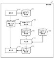
- FIG. 1 is a functional block diagram of the imaging apparatus according to the embodiment.
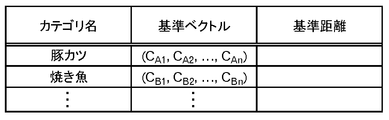
- FIG. 2 is a diagram illustrating an example of data stored in the reference data storage unit.
- FIG. 3 is a functional block diagram of a computer that performs preprocessing.
- FIG. 4 is a diagram showing a processing flow of preprocessing.
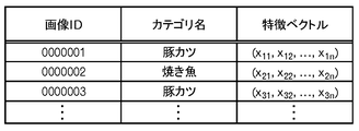
- FIG. 5 is a diagram illustrating an example of data stored in the reference feature vector storage unit.
- FIG. 6 is a diagram schematically illustrating the distribution of reference feature vectors.
- FIG. 7 is a diagram illustrating an example of data stored in the reference data storage unit.
- FIG. 8 is a diagram schematically showing the centroid vector of the category.
- FIG. 9 is a diagram for explaining identification of the reference distance.
- FIG. 10 is a diagram for explaining the reference distance.
- FIG. 9 is a diagram for explaining identification of the reference distance.
- FIG. 11 is a diagram showing a main processing flow.
- FIG. 12 is a diagram for explaining an appropriate photographing position.
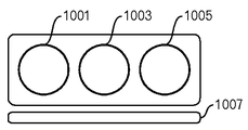
- FIG. 13 is a diagram illustrating an example of guide information.
- FIG. 14 is a diagram illustrating an example of guide information when the photographing position is appropriate.
- FIG. 15 is a diagram for describing determination as to whether or not an appropriate shooting position is approaching.
- FIG. 16 is a diagram illustrating an example of a display when approaching an appropriate shooting position.
- FIG. 17 is a diagram illustrating an example of a display when not approaching an appropriate shooting position.
- FIG. 18 is a diagram showing a main processing flow.
- FIG. 19 is a diagram illustrating an example of a display when approaching an appropriate shooting position.
- FIG. 20 is a diagram illustrating an example of a display when not approaching an appropriate shooting position.
- FIG. 21 is a functional block diagram of an imaging apparatus according to a modification of the embodiment.
- FIG. 22 is a diagram illustrating an example of information display according to the recognition result.
- FIG. 23 is a diagram illustrating an example of information display according to the recognition result.
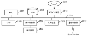
- FIG. 24 is a functional block diagram of a computer.
- FIG. 1 shows a functional block diagram of the imaging apparatus according to the present embodiment.
- the imaging apparatus 1 includes an imaging unit 101 having a function as a digital camera, an image data storage unit 103, a feature vector extraction unit 105, a feature vector storage unit 107, and processing according to the present embodiment.
- a reference data storage unit 109 that stores a reference vector and a reference distance used as a reference value for each category, a determination unit 111, a display data storage unit 113, a display unit 115, and a photographing data storage unit 117. Have.
- the imaging unit 101 generates image data of a subject via a lens and a CCD sensor or a CMOS sensor, and stores the image data in the image data storage unit 103 or the imaging data storage unit 117.
- the feature vector extraction unit 105 extracts feature vectors from the data stored in the image data storage unit 103 and stores them in the feature vector storage unit 107.
- the determination unit 111 uses the data stored in the feature vector storage unit 107 and the reference data storage unit 109 to determine whether the feature vector of the generated image data has approached the reference vector and is sufficiently close to the reference vector, Data for displaying the determination result is generated and stored in the display data storage unit 113. Further, the determination unit 111 stores the intermediately generated data in the feature vector storage unit 107.
- the display unit 115 displays data stored in the image data storage unit 103 and the display data storage unit 113.
- the reference data table in FIG. 2 includes a category name column, a reference vector column, and a reference distance column.
- the reference vector is, for example, a centroid vector of a reference feature vector extracted from image data with a known category included in the sample set.
- the reference distance is a predetermined distance set based on the distribution of reference feature vectors related to the image data of the sample set. These values are registered in the reference vector column and the reference distance column.
- the reference vector when the distance between the feature vector of the image to be photographed and the reference vector for a certain category is shorter than the reference distance, the image to be photographed is recognized as an image belonging to that category. It is judged that sufficient recognition accuracy can be obtained.
- FIG. 3 shows a functional block diagram of a computer that performs preprocessing.
- the computer 3 includes a sample storage unit 301 that stores image data in association with a category, a reference feature vector extraction unit 303, a reference feature vector storage unit 305, a reference value calculation unit 307, And a reference data storage unit 309.
- the reference feature vector extraction unit 303 extracts feature vectors from the image data stored in the sample storage unit 301 and stores them in the reference feature vector storage unit 305.
- the reference value calculation unit 307 obtains a centroid vector and a predetermined distance for each category using the data stored in the reference feature vector storage unit 305, and stores it in the reference data storage unit 309. Further, the reference value calculation unit 307 stores intermediately generated data in the reference data storage unit 309.
- the sample storage unit 301 stores image data associated with a specific category in advance. For example, image data obtained by photographing pork cutlet is stored in association with the category “pork cutlet”, and image data obtained by photographing grilled fish is stored in association with the category “baked fish”. Further, it is assumed that an image ID is attached to the image data.
- the reference feature vector extraction unit 303 identifies one unprocessed image data from the image data stored in the sample storage unit 301, and acquires image data, an image ID, and a category name (FIG. 4: step S1). . Then, the reference feature vector extraction unit 303 extracts a feature vector from the acquired image data, and stores it in the reference feature vector storage unit 305 in association with the image ID and the category name (step S3).
- the feature vector is a vector obtained by digitizing features such as a color, a pattern, or a shape included in the image data.
- a feature vector representing a color feature included in image data will be described as an example.
- the RGB color space is divided into eight equal parts for R, G, and B, and divided into 512 partial spaces. Then, the color value of each pixel of the acquired image data is acquired, and it is determined which of 512 partial spaces is included. For example, assuming that the total number of pixels is N and the number of pixels included in the i (1 ⁇ i ⁇ 512) -th partial space is NP i , the feature vector is the i-th value calculated by the following equation (1). Extracted as a 512-dimensional vector having element x i .
- FIG. 5 shows an example of a reference feature vector table stored in the reference feature vector storage unit 305.
- the reference feature vector table of FIG. 5 includes an image ID column, a category name column, and a feature vector column.
- a feature vector is extracted from the image data acquired in step S1, and registered together with an image ID and a category name previously associated with the image data.
- FIG. 6 is a diagram schematically showing the distribution of the reference feature vector.
- the reference feature vector is a two-dimensional vector for convenience.
- the reference feature vector extracted from the image data associated with the category “pork cutlet” and the reference feature vector extracted from the image data associated with the category “grilled fish” It is represented by a circle. In this way, a set of reference feature vectors is collected for each category within a certain range on the plane.
- the reference value calculation unit 307 uses the reference feature vector stored in the reference feature vector table, and the centroid vector of the reference feature vector for each category. Is stored as a reference vector in the reference data table of the reference data storage unit 309 (step S7). Centroid vectors according to the present embodiment is obtained as 512-dimensional vector to a value calculated using the following equation (2) and the i-th element c i. NVc is the number of reference feature vectors included in category c, and xm i is the i-th element related to the m-th reference feature vector included in category c. In this step, data as shown in FIG. 7 is stored in the reference data table. In the reference data table of FIG. 7, the centroid vectors calculated for each category are registered in the reference vector column.
- FIG. 8 shows a diagram schematically showing each category and the centroid vector of the category.
- FIG. 8 shows a centroid vector of reference feature vectors belonging to the category “pork cutlet” and a centroid vector of reference feature vectors belonging to the category “grilled fish”.
- the reference value calculation unit 307 calculates a reference distance for each category using the reference feature vector stored in the reference feature vector table and the reference vector stored in the reference data table, and stores the reference distance in the reference data table.
- Store (step S9) In this step, as shown in FIG. 9, for example, the distance between the reference feature vector and the reference vector is calculated for each record stored in the reference feature vector storage unit 305, and the records corresponding to the ascending order of the distance are sorted. . For example, the distance of the last record among the top 80% records is specified and stored as a reference distance. In the example of FIG. 9, the image ID is a distance D 80 in the record of 0,000,080 is identified as a reference distance.
- the distance d (c, x) is a Euclidean distance between vectors, and is calculated using, for example, the following equation (3).
- NI is the number of elements, and is 512 in this embodiment. Further, in the present embodiment, it is sufficient to be able to determine the magnitude of the distance, so only the inside of the route may be obtained.
- the reference distance from the center of gravity vector on the plane of FIG. 8 is, for example, as shown in FIG. FIG. 10 shows the standard distances in which the upper 80% of reference feature vectors are included in each category from the closest to the center of gravity vector.
- the 80% boundary is an example, and the reference distance may be determined based on other conditions.
- the reference vector and reference distance for each category are registered in the reference data table of the reference data storage unit 309 as shown in FIG.
- Such data is stored in advance in the reference data storage unit 109 of the imaging apparatus 1 and used for processing of the imaging apparatus 1.
- the imaging unit 101 generates image data at a predetermined time interval and stores it in the image data storage unit 103 (FIG. 11: step S11).
- the image data is temporarily stored in the image data storage unit 103 as image data at time t 1 .
- the stored image data is also displayed on the display unit 115 such as a liquid crystal display that also functions as a finder.
- the feature vector extraction unit 105 extracts the feature vector TV (t 1 ) from the image data stored in the image data storage unit 103, and stores it in the feature vector storage unit 107 (step S13).
- the feature vector TV (t 1 ) is extracted as a 512-dimensional vector having the i-th element x i as a value calculated using the above-described equation (1).
- the determination unit 111 also determines the distance D j (between the feature vector TV (t 1 ) stored in the feature vector storage unit 107 and each reference vector RV j registered in the reference data table of the reference data storage unit 109.
- the minimum value D min (t 1 ) of the distance D j (t 1 ) and the category associated with the reference vector RV j used to calculate the minimum value D min (t 1 ) j is specified (step S15). Further, the minimum value D min (t 1 ) of the distance D j (t 1 ) is stored in the feature vector storage unit 107.
- the distance D j (t 1 ) in this step is calculated using Equation (3) described above.
- the image data generated in step S1 belongs to the category specified in this step.
- the category to which the generated image data is supposed to belong may change.
- the category specified in this step is hereinafter referred to as a candidate category.
- the determination unit 111 reads out the reference distance associated with the candidate category from the reference data table and compares it with the minimum value D min (t 1 ) to determine whether the current shooting position is appropriate (Ste S17). In this step, when the minimum value D min (t 1 ) is smaller than the reference distance, it is determined that the shooting position is appropriate.
- FIG. 12 shows a plot of the feature vector TV (t 1 ) on the plane shown in FIG. In FIG. 12, when the point A existing within the range of the reference distance from the reference vector C of the candidate category is the feature vector TV (t 1 ), it is determined that the current shooting position is appropriate. On the other hand, when the point B that does not exist within the range of the reference distance from the reference vector C of the candidate category is the feature vector TV (t 1 ), it is determined that the current shooting position is not appropriate.
- the determination unit 111 When it is determined that the shooting position is appropriate, the determination unit 111 generates data for displaying that the shooting position is appropriate, and stores the data in the display data storage unit 113 (step S19).
- guide information as shown in FIG. 13 is generated as data to be displayed on the display unit 115.
- the guide information in FIG. 13 includes an area 1001 indicating an appropriate shooting position, an area 1003 indicating that it is approaching an appropriate shooting position, an area 1005 indicating that it is not approaching an appropriate shooting position, And a region 1007 indicating a distance. If it is determined in step S17 that the shooting position is appropriate, the data indicating that the shooting position is appropriate is displayed as an area indicating that the shooting position is appropriate, for example, as shown in FIG.
- Data for displaying an image in which 1001 is painted in blue is generated. Further, in the area 1007 indicating the distance, for example, a bar indicating the minimum value D min (t 1 ) that is the distance from the feature vector TV (t 1 ) to the reference vector RV j of the candidate category is converted into a predetermined length. Data for displaying is generated. In this case, the increase / decrease in the distance is represented by the change in the length of the bar based on the conversion rate such that the minimum value D min (t 1 ) obtained for the first time becomes the length of the region 1007.
- step S15 the minimum value D min (t 1 ) calculated in step S15 is multiplied by (length of region 1007 / minimum value D min (t 1 ) obtained for the first time) to display the value.
- the length of the bar to be calculated is calculated. From this bar, the user can recognize the increase or decrease of the distance.
- Such a conversion rate is also stored in the display data storage unit 113, for example. Then, the process proceeds to step S31.
- the minimum value D min (t 1 ) obtained for the first time may be, for example, 50% the length of the area 1007. In this way, it is possible to represent a change in length even when the distance increases from the minimum value D min (t 1 ) obtained at the first time.
- the area 1007 may indicate a scale corresponding to the reference distance. In this way, the distance to the appropriate shooting position can be grasped.
- a bar having a length corresponding to the distance to the reference vector a bar having a length corresponding to a distance from the center of gravity in the vector space to the hypersurface away from the reference distance is displayed in the area 1007. Good. In that case, the length of the bar is determined by converting a value obtained by subtracting the reference distance for the candidate category from the minimum value D min (t 1 ).
- the minimum value D min (t 1 ) calculated at time t 1 is compared with the minimum value D min (t 0 ) calculated at time t 0 before that, and appropriate photographing is performed.
- an image is displayed in which a region 1003 indicating that it is approaching an appropriate shooting position in FIG. 13 is filled with green. If it is determined that the camera has not approached the appropriate shooting position, for example, an image in which an area 1005 indicating that the camera has not approached the appropriate shooting position is filled with red is displayed.
- the determination unit 111 determines whether data at time t 0 exists in the feature vector table of the feature vector storage unit 107 (step S21). If the data at time t 0 is not present, the determination unit 111, a minimum value D min (t 1) at time t 1, the feature vector storage unit 107 as data at time t 0 (the minimum value D min (t 0)) (Step S23). Then, the process returns to step S11.
- step S21 the determination unit 111, the minimum value D min of the minimum value D min (t 0) and time t 1 at time t 0 from the feature vector storage unit 107 (T 1 ) is read, and D min (t 0 ) and D min (t 1 ) are compared to determine whether or not an appropriate shooting position is approaching (step S25).
- D min (t 1 ) is smaller than D min (t 0 )
- FIG. 15 is a diagram in which the feature vector TV (t 0 ) and the feature vector TV (t 1 ) are plotted on the plane of FIG. In FIG.
- the determination unit 111 When it is determined that the camera is approaching an appropriate shooting position, the determination unit 111 generates display data indicating that the camera is approaching an appropriate shooting position, and stores the display data in the display data storage unit 113 (step S27). In this step, in the guide information shown in FIG. 13, for example, data for displaying an image in which an area 1003 indicating that it is approaching an appropriate shooting position is filled with green is generated. Further, data for displaying a bar having a length corresponding to the minimum value D min (t 1 ) is also generated. Then, the process proceeds to step S31.
- step S25 when it is determined in step S25 that the camera has not approached the appropriate shooting position, the determination unit 111 generates display data indicating that the camera has not approached the appropriate shooting position, and stores the display data in the display data storage unit 113 ( Step S29).
- Step S29 in the guide information shown in FIG. 13, for example, data for displaying an image in which an area 1005 indicating that it is not approaching an appropriate shooting position is painted in red is generated. Further, data for displaying a bar having a length corresponding to the minimum value D min (t 1 ) is also generated. Then, the process proceeds to step S31.
- Step S19 after step S27 or step S29, the display unit 115, the image data at time t 1 stored in the image data storage unit 103, overlapping the data stored in the display data storage unit 113 Displayed (step S31).
- the display data generated in step S27 is displayed by being superimposed on the image data generated in step S1.
- the rectangular frame illustrated in FIG. 16 represents an example of a shooting range when shooting from an appropriate shooting position. This rectangular frame is shown for convenience, and is not displayed on the display unit 115.
- the display data generated in step S29 is displayed superimposed on the image data generated in step S1.
- step S19 (for example, the display data shown in FIG. 14) is displayed superimposed on the image data generated in step S1. Thereafter, the processing shifts to the processing in FIG.
- the bar displayed in the area 1007 represents a distance corresponding to the minimum value D min (t 1 ) and does not represent an actual distance from the imaging device 1 to the subject. That is, in FIGS. 16 and 17, the length of the bar is shortened when approaching the subject, but as shown in FIGS. 19 and 20, the length of the bar may be shortened when moving away from the subject. is there. While referring to such a display, the user can change the composition of the image data such as the actual distance between the imaging apparatus 1 and the subject or the angle at which the subject is photographed, or change the brightness of the photographing environment in some cases. The distance to the appropriate shooting position should be shortened.
- the determination unit 111 determines whether shooting is instructed by the user (step S33). If it is determined that the user has instructed shooting via an input unit such as a shutter button (not shown), for example, the imaging unit 101 generates image data and stores it in the shooting data storage unit 117 (step S35). Note that the photographing data storage unit 117 is a nonvolatile memory or the like.
- step S37 determines whether the end of the process has been instructed. For example, when the power of the imaging apparatus 1 is turned off or when the imaging apparatus 1 is instructed to stop the function according to the present embodiment, the processing is ended. On the other hand, if the end of the process is not instructed, the process returns to step S23 (FIG. 11) via the terminal B. In other words, may be held as the minimum value D min of the time t 1 the minimum value D min (t 0) of (t 1) the time t 0, the processing image data that is newly generated as image data at time t 1 repeat.
- the feature vector also changes depending on the composition such as the position and size of the subject in the image. That is, unless image data is generated with a composition that shows the same characteristics as an image prepared in advance, the feature vectors cannot be compared well, and the recognition accuracy decreases. However, it is difficult for the user to understand an appropriate composition for shooting a subject, and it is difficult to generate image data from an appropriate shooting position. Since the imaging apparatus 1 according to the present embodiment guides the user so that the feature vector of the generated image data approaches the reference vector of the candidate category, it is possible to improve the recognition accuracy of the image data captured according to the guide. it can.
- the transmission unit 119 and the reception unit 121 may be provided in the above-described imaging device 1 like the imaging device 10 illustrated in FIG. Then, the transmission unit 119 transmits the image data stored in the photographing data storage unit 117 to an image recognition device (not shown), and the reception unit 121 receives information according to the recognition result from the image recognition device and displays the display data. You may make it store in the storage part 113. FIG. If the display unit 115 displays the information obtained in this way, the user can check information corresponding to the recognition result of the captured image on the spot.
- the image recognition device recognizes the disease name from the image data of the crops affected by the disease, and returns information such as a coping method stored in association with the disease name to the imaging device 10.
- the display unit 115 of the imaging apparatus 10 displays information such as a countermeasure.
- the image recognition device recognizes dishes from image data of dishes taken at the time of meals, and captures information such as types of staple foods, main dishes, side dishes, and calories that are stored in association with the dishes.
- the image recognition apparatus may hold history data about the user's meal and return a message prepared in advance based on the contents.
- the imaging device 1 may perform the processing of the image recognition device described here.
- the present technology is not limited to this.
- the functional block diagram is an example, and may not necessarily match the actual program module configuration.
- the processing flow as long as the processing result does not change, the order of the steps may be changed or may be performed in parallel.
- the imaging apparatus 1 includes a digital camera, a digital video camera, a mobile phone with a camera, a portable information terminal having a camera and a network connection, a portable computer connected to the camera or having a built-in camera, etc. This is realized by a portable terminal having a function as a camera.
- an application program for causing such a portable terminal to function as the imaging device 1 or the imaging device 10 of the present embodiment may be provided.
- the reference vector and the reference distance are stored in the reference data storage unit 109 of the imaging apparatus 1. Since the image sample set and reference feature vectors used for calculating these are not stored, the amount of data held by the imaging apparatus 1 can be small.
- the data stored in the reference data storage unit 109 may be added or updated by being received by the imaging apparatus 1.
- pre-processing for generating reference data can be performed by the imaging apparatus 1.
- the category related to the reference vector that is closest to the feature vector of the generated image data is assumed as the candidate category. Therefore, the user can use the imaging apparatus 1 without performing special settings. However, it may be set such that the user narrows down the category to which the subject belongs, such as “cooking” or “main dish”, “agricultural crop disease”, or “cabbage disease”. For example, if the user selects a category before shooting and the imaging apparatus 1 performs the process according to the present embodiment for the category, the user can be guided to approach the reference vector for the category. it can. Further, a selection method that selects a large category including a plurality of small categories may be employed. By doing in this way, the user's burden about selection can be eased and recognition accuracy can be improved further.
- the imaging device 1 may download data such as a reference vector for the selected category from the image recognition device or the like.
- the feature vector to be adopted is not limited to a color feature vector. It is also possible to employ feature vectors for patterns and shapes, such as feature vectors representing textures, feature vectors based on local descriptors, and the like. Further, even for a color feature vector, a histogram of a predetermined color may be used instead of RGB. Further, the determination may be made by combining a plurality of feature amounts.
- the guide information shown in FIG. 13 is an example. You may use figures other than circles and bars, and display textual guide information such as “appropriate shooting position”, “approaching appropriate shooting position”, or “not approaching appropriate shooting position” May be.
- the color used for filling may be a combination of other colors or a single color.
- the reference of the conversion rate may be known by putting a scale on the bar, and the conversion rate may be appropriately changed according to the distance.
- guide information based on the actual positional relationship between the subject and the imaging device 1 may be displayed in the area 1007 instead of displaying guide information based on the distance between vectors. For example, the movement of the image pickup apparatus 1 when approaching an appropriate shooting position is acquired by a sensor or the like, and how the image pickup apparatus 1 should be moved is guided.
- the computer and the image recognition apparatus that perform the preprocessing described above are computer apparatuses, and are connected to a memory 2501, a CPU 2503, a hard disk drive (HDD) 2505, and a display device 2509 as shown in FIG.
- a display control unit 2507, a drive device 2513 for a removable disk 2511, an input device 2515, and a communication control unit 2517 for connecting to a network are connected by a bus 2519.
- An operating system (OS: Operating System) and an application program for performing the processing in this embodiment are stored in the HDD 2505, and are read from the HDD 2505 to the memory 2501 when executed by the CPU 2503.
- OS Operating System
- the CPU 2503 controls the display control unit 2507, the communication control unit 2517, and the drive device 2513 according to the processing content of the application program, and performs a predetermined operation. Further, data in the middle of processing is mainly stored in the memory 2501, but may be stored in the HDD 2505. In an embodiment of the present technology, an application program for performing the above-described processing is stored in a computer-readable removable disk 2511 and distributed, and installed from the drive device 2513 to the HDD 2505. In some cases, the HDD 2505 may be installed via a network such as the Internet and the communication control unit 2517. Such a computer apparatus realizes various functions as described above by organically cooperating hardware such as the CPU 2503 and the memory 2501 described above with programs such as the OS and application programs. . Note that the imaging device 1 or the imaging device 10 may be a computer device provided with an imaging unit including a lens and an imaging element.
- the imaging apparatus (A) generates image data and stores the image data in a data storage unit, and (B) features vectors representing the features of the image from the image data stored in the data storage unit.
- a feature vector extraction unit that extracts and stores the feature vector in a feature vector storage unit;
- C a reference vector storage unit that stores a reference vector that serves as a reference for image features;
- D a feature vector storage unit that stores the reference vector.
- the imaging unit generates by comparing the second distance between the feature vector related to the second image data generated at the second time earlier and the reference vector stored in the reference vector storage unit Having a determination section for determining whether or not approaching to the image data which the image data corresponding to the reference vector, and a display unit for displaying the (E) of the determination unit determination result.
- the feature vector may change depending on the position and size of the subject in the image, that is, the composition even if the subject is the same. Therefore, when performing image recognition using a feature vector, it is preferable that the composition is the same as that in the image corresponding to the reference vector.
- the display unit displays whether or not the image data corresponding to the reference vector is closer than before, so that the composition of the image that the user is going to shoot is appropriate. It will be possible to lead to. In other words, it is possible to support the shooting of an image with improved recognition accuracy in image recognition using feature vectors.
- the reference vector storage unit may further store (C1) a threshold expressed as a predetermined distance from the reference vector. Then, (D1) when the first distance is smaller than the threshold value stored in the reference vector storage unit, the determination unit further determines that the first image data is in a predetermined appropriate state. May be. When the first distance is smaller than the threshold value, it can be said that the composition of the image that the user intends to photograph has approached the composition in the image corresponding to the reference vector by a predetermined reference or more. In such a case, if it is further determined that the first image data is in a predetermined appropriate state and the determination result is displayed, it can be seen that the user may shoot.
- the reference vector storage unit may store (C2) a plurality of reference vectors.
- the determination unit calculates a minimum value of the first distance and a minimum value of the second distance among the plurality of first distances and the plurality of second distances obtained using the plurality of reference vectors. The determination may be made by using.
- a plurality of reference vectors a plurality of types of image data can be identified. Further, if the minimum value of the first distance and the minimum value of the second distance are automatically selected and used, the user is not aware of the type of image to be shot and corresponds to a plurality of reference vectors.
- the imaging apparatus can be used without understanding the preferred composition of the image to be performed.
- the reference vector may be a centroid vector of feature vectors prepared for each category and extracted for the image data of each image belonging to the category. In this way, whether or not the recognition accuracy is improved can be accurately determined based on the centroid vector related to the set of images prepared for each category.
- the determination unit (D2) generates distance data representing the magnitude of the distance between the feature vector and the reference vector related to the first image data
- the display unit (E1) further generates the generated distance data. You may make it display.
- the distance data is, for example, a bar whose length expands or contracts according to the distance, or a numerical value. In this way, the user can grasp the magnitude of the distance intuitively or quantitatively.
- a program for causing a computer to perform the processing according to the above method can be created.
- the program can be a computer-readable storage medium such as a flexible disk, a CD-ROM, a magneto-optical disk, a semiconductor memory, or a hard disk. It is stored in a storage device.
- the intermediate processing result is temporarily stored in a storage device such as a main memory.
Landscapes
- Engineering & Computer Science (AREA)
- Multimedia (AREA)
- Signal Processing (AREA)
- Studio Devices (AREA)
- Indication In Cameras, And Counting Of Exposures (AREA)
Abstract
本撮像装置は、画像データを生成し、データ格納部に格納する撮像部と、データ格納部に格納された画像データから画像の特徴を表す特徴ベクトルTVを抽出し、特徴ベクトル格納部に格納する特徴ベクトル抽出部と、画像の特徴についての基準となる基準ベクトルRVを格納している基準ベクトル格納部と、特徴ベクトル格納部に格納され且つ第1の時刻に生成された第1画像データに係るTVと基準ベクトル格納部に格納されているRVとの第1距離と、特徴ベクトル格納部に格納され且つ第1の時刻より前の第2の時刻に生成された第2画像データに係るTVと基準ベクトル格納部に格納されているRVとの第2距離とを比較することで、撮像部が生成した画像データがRVに相当する画像データに近づいているか否かを判定する判定部と、判定部の判定結果を表示する表示部とを有する。
Description
本技術は、画像の撮影を支援するための技術に関する。
何らかの被写体を撮影した画像からその被写体を認識する技術が存在している。例えば、画像から被写体の属するカテゴリを認識する技術では、まず、カテゴリが既知である画像の集合を用意し、各画像に表れた色、模様又は形状等の特徴をベクトルとして数量化した特徴ベクトルを抽出する。そして、ベクトル空間における各カテゴリの特徴ベクトル群の分布に基づいて、認識対象の画像の被写体が属するカテゴリを特定する。
一方、写真撮影時に推奨する構図を案内する技術としては、例えば、ユーザによる撮影対象の種類選択に応じて、画像圧縮の観点から推奨される構図をガイドする技術がある。他には、連続的に撮像された画像について空間周波数成分をもとに良否評価する技術や、過去に撮影した写真と同じ構図及びパースで撮影できるようにガイドとなる情報を表示する技術も存在している。また、構図を自動的に調整する技術として、ナンバープレートを撮影する際に、モデル画像における大きさとほぼ一致させるように画角を調整する技術も存在している。
ここで、特徴ベクトルを用いた画像認識では、単純に被写体が大きく写っているとかピントがぼけていないといった条件だけでは、認識精度が十分に上がらない場合がある。しかし、特徴ベクトルを用いた画像認識において認識精度が向上するように画像の撮影を支援するための技術は存在していない。
C.M.ビショップ(著)、元田浩、栗田多喜夫、樋口知之、松本裕治、村田昇(翻訳)、パターン認識と機械学習 上(下)-ベイズ理論による統計的予測、シュプリンガー・ジャパン株式会社、ISBN:978-4431100133(下:978-4431100317)
従って、本技術の目的は、一側面として、画像認識において認識精度が向上するような画像の撮影を支援するための技術を提供することである。
本実施の形態に係る撮像装置は、(A)画像データを生成し、データ格納部に格納する撮像部と、(B)データ格納部に格納された画像データから画像の特徴を表す特徴ベクトルを抽出し、特徴ベクトル格納部に格納する特徴ベクトル抽出部と、(C)画像の特徴についての基準となる基準ベクトルを格納している基準ベクトル格納部と、(D)特徴ベクトル格納部に格納され且つ第1の時刻に生成された第1の画像データに係る特徴ベクトルと基準ベクトル格納部に格納されている基準ベクトルとの第1の距離と、特徴ベクトル格納部に格納され且つ第1の時刻より前の第2の時刻に生成された第2の画像データに係る特徴ベクトルと基準ベクトル格納部に格納されている基準ベクトルとの第2の距離とを比較することで、撮像部が生成した画像データが基準ベクトルに相当する画像データに近づいているか否かを判定する判定部と、(E)判定部の判定結果を表示する表示部とを有する。
画像認識において認識精度が向上するような画像の撮影を支援するための技術を提供することができるようになる。
図1に、本実施の形態に係る撮像装置の機能ブロック図を示す。本実施の形態に係る撮像装置1は、デジタルカメラとしての機能を有する撮像部101と、画像データ格納部103と、特徴ベクトル抽出部105と、特徴ベクトル格納部107と、本実施の形態の処理において基準値として用いられる基準ベクトル及び基準距離をカテゴリ毎に格納している基準データ格納部109と、判定部111と、表示データ格納部113と、表示部115と、撮影データ格納部117とを有する。
撮像部101は、レンズ及びCCDセンサ又はCMOSセンサ等を介して被写体の画像データを生成し、画像データ格納部103又は撮影データ格納部117に格納する。特徴ベクトル抽出部105は、画像データ格納部103に格納されたデータから特徴ベクトルを抽出し、特徴ベクトル格納部107に格納する。判定部111は、特徴ベクトル格納部107及び基準データ格納部109に格納されたデータを用いて、生成された画像データの特徴ベクトルが基準ベクトルに近づいたか、及び基準ベクトルに十分近いか判断し、判断結果を表示するためのデータを生成して表示データ格納部113に格納する。また、判定部111は、中間的に生成したデータを特徴ベクトル格納部107に格納する。表示部115は、画像データ格納部103及び表示データ格納部113に格納されたデータを表示する。
撮像装置1の基準データ格納部109には、例えば図2に示すような基準データテーブルが予め格納されているものとする。図2の基準データテーブルには、カテゴリ名の列と、基準ベクトルの列と、基準距離の列とが含まれている。本実施の形態において、基準ベクトルは、例えば、サンプル集合に含まれる、カテゴリが既知の画像データから抽出された参照特徴ベクトルの重心ベクトルである。また、基準距離は、サンプル集合の画像データに係る参照特徴ベクトルの分布に基づき設定される所定の距離である。そして、基準ベクトルの列及び基準距離の列にはこれらの値を登録しておく。なお、本実施の形態では、撮影しようとしている画像の特徴ベクトルとあるカテゴリに係る基準ベクトルとの距離が基準距離よりも短い場合、撮影しようとしている画像は、そのカテゴリに属する画像であると認識するのに十分な認識精度を得られるものと判断する。
ここで、基準データ格納部109に格納されるデータを事前に準備する処理について、図3乃至図10を用いて説明しておく。なお、本処理は、例えば一般的なコンピュータにより実施され、得られたデータが撮像装置1の基準データ格納部109に格納されるものとする。
まず、図3に、前処理を行うコンピュータの機能ブロック図を示す。本実施の形態に係るコンピュータ3は、カテゴリと関連付けて画像データを格納しているサンプル格納部301と、参照特徴ベクトル抽出部303と、参照特徴ベクトル格納部305と、基準値算出部307と、基準データ格納部309とを有する。
参照特徴ベクトル抽出部303は、サンプル格納部301に格納された画像データから特徴ベクトルを抽出し、参照特徴ベクトル格納部305に格納する。また、基準値算出部307は、参照特徴ベクトル格納部305に格納されたデータを用いて、カテゴリ毎に、重心ベクトル及び所定の距離を求め、基準データ格納部309に格納する。また、基準値算出部307は、中間的に生成したデータを基準データ格納部309に格納する。
次に、図4乃至図10を用いて、図3に示したコンピュータ3の処理について説明する。なお、サンプル格納部301には、特定のカテゴリと関連付けられた画像データが予め格納されているものとする。例えば、カテゴリ「豚カツ」に関連付けられて、豚カツを撮影した画像データが格納されており、カテゴリ「焼き魚」に関連付けられて、焼き魚を撮影した画像データが格納されている。また、画像データには画像IDが付されているものとする。
まず、参照特徴ベクトル抽出部303は、サンプル格納部301に格納された画像データから未処理の画像データを1つ特定し、画像データ、画像ID及びカテゴリ名を取得する(図4:ステップS1)。そして、参照特徴ベクトル抽出部303は、取得した画像データから特徴ベクトルを抽出し、画像ID及びカテゴリ名と関連付けて参照特徴ベクトル格納部305に格納する(ステップS3)。
特徴ベクトルは、画像データに含まれる色、模様又は形状等の特徴を数値化したベクトルである。本実施の形態では、画像データに含まれる色の特徴を表す特徴ベクトルを例に説明する。例えばRGB色空間をR、G及びBについてそれぞれ8等分することで512の部分空間に分割する。そして、取得した画像データの各画素の色値を取得し、512の部分空間のいずれに含まれるか判断する。例えば、総画素数をN、i(1≦i≦512)番目の部分空間に含まれる画素数をNPiとすると、特徴ベクトルは、次の式(1)で算出される値をi番目の要素xiとする512次元ベクトルとして抽出される。

また、図5に、参照特徴ベクトル格納部305に格納される参照特徴ベクトルテーブルの一例を示す。図5の参照特徴ベクトルテーブルは、画像IDの列と、カテゴリ名の列と、特徴ベクトルの列とを有する。ステップS3では、ステップS1で取得した画像データから特徴ベクトルが抽出され、予め画像データに関連付けられていた画像ID及びカテゴリ名と共に登録される。
その後、参照特徴ベクトル抽出部303は、サンプル格納部301に未処理の画像データが存在するか判断する(ステップS5)。未処理の画像データが存在すると判断された場合、ステップS1へ戻る。その後、ステップS3の処理が繰り返されて、複数の参照特徴ベクトルが登録される。ここで、図6に、参照特徴ベクトルの分布を模式的に表した図を示す。なお、参照特徴ベクトルは、便宜上2次元ベクトルとしている。図6には、カテゴリ「豚カツ」に関連付けられた画像データから抽出された参照特徴ベクトルと、カテゴリ「焼き魚」に関連付けられた画像データから抽出された参照特徴ベクトルとが、平面上に×印又は○印で表されている。このように、参照特徴ベクトルの集合は、平面上においてある範囲にカテゴリ毎にまとまっている。
一方、ステップS5において未処理の画像データが存在しないと判断された場合、基準値算出部307は、参照特徴ベクトルテーブルに格納された参照特徴ベクトルを用いて、カテゴリ毎に参照特徴ベクトルの重心ベクトルを算出し、基準データ格納部309の基準データテーブルに基準ベクトルとして格納する(ステップS7)。本実施の形態に係る重心ベクトルは、次の式(2)を用いて算出される値をi番目の要素ciとする512次元ベクトルとして求められる。
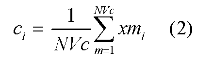
なお、NVcは、カテゴリcに含まれる参照特徴ベクトルの数であり、xmiはカテゴリcに含まれるm番目の参照特徴ベクトルに係るi番目の要素である。また、本ステップでは、図7に示すようなデータが基準データテーブルに格納される。図7の基準データテーブルには、カテゴリ毎に算出された重心ベクトルが基準ベクトルの列に登録されている。
また、図8に、各カテゴリと当該カテゴリの重心ベクトルを模式的に表した図を示す。図8には、カテゴリ「豚カツ」に属する参照特徴ベクトルの重心ベクトルと、カテゴリ「焼き魚」に属する参照特徴ベクトルの重心ベクトルとが示されている。
その後、基準値算出部307は、参照特徴ベクトルテーブルに格納されている参照特徴ベクトルと基準データテーブルに格納されている基準ベクトルとを用いて、カテゴリ毎に基準距離を算出し、基準データテーブルに格納する(ステップS9)。本ステップでは、図9に示すように、例えば参照特徴ベクトル格納部305に格納されているレコード毎に参照特徴ベクトルと基準ベクトルとの距離を算出し、当該距離の昇順に対応するレコードをソートする。そして、例えば上位8割のレコードのうち最後のレコードの距離を特定し、基準距離として格納する。図9の例では、画像IDが0000080のレコードにおける距離D80が基準距離として特定される。
ここで、距離d(c,x)は、ベクトル間のユークリッド距離であり、例えば次の式(3)を用いて算出される。
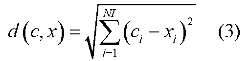
なお、NIは要素の数であり、本実施の形態では512である。また、本実施の形態では距離の大小を判定することができれば十分であるため、ルートの内部のみを求めるようにしてもよい。
また、図8の平面上において重心ベクトルからの基準距離を示すと、例えば図10のようになる。図10には、各カテゴリにおいて、重心ベクトルに近いものから上位8割の参照特徴ベクトルが含まれるような基準距離が示されている。なお、8割という境界は一例であり、他の条件を基に基準距離を決めるようにしてもよい。
以上のような処理により、基準データ格納部309の基準データテーブルには、図2に示したようにカテゴリ毎の基準ベクトル及び基準距離が登録される。そして、このようなデータが撮像装置1の基準データ格納部109に予め格納され、撮像装置1の処理に用いられる。
次に、図11乃至図23を用いて、図1に示した撮像装置1の処理について説明する。まず、撮像部101は、所定の時間間隔で画像データを生成し、画像データ格納部103に格納する(図11:ステップS11)。本ステップでは、例えば、時刻t1の画像データとして一時的に画像データ格納部103に格納する。格納された画像データは、ファインダの機能を兼ねた液晶ディスプレイ等である表示部115にも表示される。
次に、特徴ベクトル抽出部105は、画像データ格納部103に格納された画像データから特徴ベクトルTV(t1)を抽出し、特徴ベクトル格納部107に格納する(ステップS13)。特徴ベクトルTV(t1)は、上で述べた式(1)を用いて算出される値をi番目の要素xiとする512次元ベクトルとして抽出される。また、判定部111は、特徴ベクトル格納部107に格納されている特徴ベクトルTV(t1)と基準データ格納部109の基準データテーブルに登録されている各基準ベクトルRVjとの距離Dj(t1)を算出し、距離Dj(t1)の最小値Dmin(t1)と当該最小値Dmin(t1)を算出するために用いられた基準ベクトルRVjに関連付けられたカテゴリjを特定する(ステップS15)。また、距離Dj(t1)の最小値Dmin(t1)を特徴ベクトル格納部107に格納しておく。ここで、本ステップにおける距離Dj(t1)は、上で述べた式(3)を用いて算出される。なお、本実施の形態では、ステップS1で生成された画像データは、本ステップで特定されたカテゴリに属するものと想定する。また、本実施の形態に係る処理が繰り返される中で、生成された画像データが属すると想定されるカテゴリは変化することもあり得る。なお、説明の便宜上、本ステップで特定されたカテゴリを以降は候補カテゴリと呼ぶこととする。
そして、判定部111は、基準データテーブルから、候補カテゴリに関連付けられている基準距離を読み出し、最小値Dmin(t1)と比較することにより、現在の撮影位置が適切であるか判断する(ステップS17)。本ステップでは、最小値Dmin(t1)が基準距離よりも小さい場合に、撮影位置は適切であると判断する。図10で示した平面上に特徴ベクトルTV(t1)をプロットした図を、図12に示す。図12において、候補カテゴリの基準ベクトルCから基準距離の範囲内に存在する点Aが特徴ベクトルTV(t1)である場合、現在の撮影位置は適切であると判断する。一方、候補カテゴリの基準ベクトルCから基準距離の範囲内に存在しない点Bが特徴ベクトルTV(t1)である場合、現在の撮影位置は適切でないと判断する。
撮影位置が適切であると判断された場合、判定部111は、撮影位置が適切である旨を表示するためのデータを生成し、表示データ格納部113に格納する(ステップS19)。本実施の形態では、例えば図13に示すようなガイド情報を、表示部115に表示するためのデータとして生成する。図13のガイド情報は、適切な撮影位置であることを示す領域1001と、適切な撮影位置に近づいていることを示す領域1003と、適切な撮影位置に近づいていないことを示す領域1005と、距離を示す領域1007とを含む。ステップS17において撮影位置が適切であると判断された場合には、撮影位置が適切である旨を表示するためのデータとして、例えば図14に示すような、適切な撮影位置であることを示す領域1001を青で塗りつぶした画像を表示するためのデータを生成する。また、距離を示す領域1007に、例えば、特徴ベクトルTV(t1)から候補カテゴリの基準ベクトルRVjまでの距離である最小値Dmin(t1)を所定の長さに換算して示すバーを表示するためのデータを生成する。この場合、初回に得られた最小値Dmin(t1)が領域1007の長さとなるような換算率に基づいて距離の増減をバーの長さの変化で表すようにする。すなわち、本ステップでは、ステップS15で算出された最小値Dmin(t1)に対し、(領域1007の長さ/初回に得られた最小値Dmin(t1))を乗じることにより、表示すべきバーの長さを算出するようにする。このバーからも、ユーザは距離の増減を認識することができるようになる。なお、このような換算率も例えば表示データ格納部113に格納しておく。そして、ステップS31へ移行する。
なお、初回に得られた最小値Dmin(t1)が、例えば領域1007の5割の長さになるようにしてもよい。このようにすれば、初回に得られた最小値Dmin(t1)より距離が増加した場合にも長さの変化を表すことができるようになる。さらに、領域1007には基準距離に相当する目盛を示すようにしてもよい。このようにすれば、適切な撮影位置までの距離を把握することができる。また、領域1007に、基準ベクトルまでの距離に相当する長さを有するバーではなく、ベクトル空間における重心から基準距離離れた超曲面までの距離に相当する長さを有するバーを示すようにしてもよい。その場合は、最小値Dmin(t1)から候補カテゴリについての基準距離を引いた値を換算してバーの長さを決定する。
また、後に説明する処理において、時刻t1に算出された最小値Dmin(t1)とそれ以前の時刻t0に算出された最小値Dmin(t0)とを比較し、適切な撮影位置に近づいていると判断された場合には、例えば図13の適切な撮影位置に近づいていることを示す領域1003を緑色で塗りつぶした画像を表示する。また、適切な撮影位置に近づいていないと判断された場合には、例えば適切な撮影位置に近づいていないことを示す領域1005を赤で塗りつぶした画像を表示する。
ステップS17において現在の撮影位置が適切でないと判断された場合、判定部111は、特徴ベクトル格納部107の特徴ベクトルテーブルに時刻t0のデータが存在するか判断する(ステップS21)。時刻t0のデータが存在しない場合、判定部111は、時刻t1における最小値Dmin(t1)を、時刻t0のデータ(最小値Dmin(t0))として特徴ベクトル格納部107に保持しておく(ステップS23)。そして、ステップS11に戻る。
一方、ステップS21において時刻t0のデータが存在すると判断された場合、判定部111は、特徴ベクトル格納部107から時刻t0における最小値Dmin(t0)及び時刻t1における最小値Dmin(t1)を読み出し、Dmin(t0)とDmin(t1)とを比較することにより適切な撮影位置に近づいているか判断する(ステップS25)。本ステップでは、Dmin(t0)よりもDmin(t1)の方が小さい場合、適切な撮影位置に近づいていると判断する。図10の平面上に特徴ベクトルTV(t0)及び特徴ベクトルTV(t1)をプロットした図を、図15に示す。図15において、例えば、候補カテゴリの基準ベクトルFから遠い点Dが特徴ベクトルTV(t0)であり、基準ベクトルFに近い点Eが特徴ベクトルTV(t1)である場合、Dmin(t0)よりもDmin(t1)が小さくなるため、適切な撮影位置に近づいていると判断する。一方、例えば、候補カテゴリの基準ベクトルFから遠い点Dが特徴ベクトルTV(t1)であり、基準ベクトルFに近い点Eが特徴ベクトルTV(t0)である場合、Dmin(t0)よりもDmin(t1)が小さくならないため、適切な撮影位置に近づいていないと判断する。
適切な撮影位置に近づいていると判断された場合、判定部111は、適切な撮影位置に近づいている旨の表示データを生成し、表示データ格納部113に格納する(ステップS27)。本ステップでは、図13に示したガイド情報において、例えば適切な撮影位置に近づいていることを示す領域1003を緑色で塗りつぶした画像を表示するためのデータを生成する。また、最小値Dmin(t1)に相当する長さを有するバーを表示するためのデータも生成する。そして、ステップS31へ移行する。
一方、ステップS25において、適切な撮影位置に近づいていないと判断された場合、判定部111は、適切な撮影位置に近づいていない旨の表示データを生成し、表示データ格納部113に格納する(ステップS29)。本ステップでは、図13に示したガイド情報において、例えば適切な撮影位置に近づいていないことを示す領域1005を赤で塗りつぶした画像を表示するためのデータを生成する。また、最小値Dmin(t1)に相当する長さを有するバーを表示するためのデータも生成する。そして、ステップS31へ移行する。
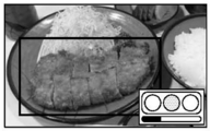
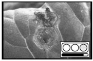
ステップS19、ステップS27又はステップS29の後、表示部115は、画像データ格納部103に格納されている時刻t1の画像データに対して、表示データ格納部113に格納されているデータを重ねて表示する(ステップS31)。例えば、適切な撮影位置に近づいている場合は、図16に示すように、ステップS1で生成された画像データに重畳して、ステップS27で生成された表示データを表示する。なお、図16に示した矩形の枠は、適切な撮影位置から撮影した場合における撮影範囲の一例を表している。この矩形の枠は便宜的に示したものであり、表示部115に表示されるものではない。一方、適切な撮影位置に近づいていない場合、図17に示すように、ステップS1で生成された画像データに重畳して、ステップS29で生成された表示データを表示する。図17にも適切な撮影位置から撮影した場合における撮影範囲の一例を表す枠を便宜的に示している。図17の撮影範囲と内部の枠とのずれは図16の場合よりも大きく、撮影位置は適切な撮影位置から遠ざかっている。ユーザはこれを右下のガイド情報から認識することができる。また、撮影位置が適切である場合、ステップS1で生成された画像データに重畳して、ステップS19で生成された表示データ(例えば、図14に示した表示データ)を表示する。その後、端子Aを介して図18の処理へ移行する。
なお、領域1007に表示されるバーは、最小値Dmin(t1)に相当する距離を表すものであり、撮像装置1から被写体までの現実の距離を表すものではない。すなわち、図16及び図17では被写体に近づいた場合にバーの長さが短くなっているが、図19及び図20に示すように、被写体から遠ざかった場合にバーの長さが短くなる場合もある。ユーザはこのような表示を参考にしつつ、撮像装置1と被写体の現実の距離又は被写体を撮影する角度等、画像データの構図を変えたり、場合によっては撮影環境の明るさを変えたりすることで、適切な撮影位置までの距離が短くなるようにする。
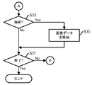
図18の説明に移行して、端子Aの後、判定部111は、ユーザから撮影が指示されたか判断する(ステップS33)。図示していないシャッターボタン等の入力部を介してユーザが撮影を指示したと判断された場合、例えば撮像部101は、画像データを生成して撮影データ格納部117に格納する(ステップS35)。なお、撮影データ格納部117は、不揮発性メモリ等である。
一方、ステップS33においてユーザから撮影を指示されていないと判断された場合、又はステップS35の後、判定部111は、処理の終了が指示されたか判断する(ステップS37)。例えば、撮像装置1の電源がオフにされた場合、又は撮像装置1に対して本実施の形態に係る機能の停止が指示された場合等には、処理を終了する。一方、処理の終了が指示されていない場合、処理は端子Bを介してステップS23(図11)へ戻る。すなわち、時刻t1の最小値Dmin(t1)を時刻t0の最小値Dmin(t0)として保持しておき、新たに生成された画像データを時刻t1の画像データとして処理を繰り返す。
上で述べたように、特徴ベクトルは、画像の中での被写体の位置や大きさといった構図等によっても変化してしまう。すなわち、予め用意された画像と同じような特徴を示す構図で画像データを生成しなければ、うまく特徴ベクトルの比較を行うことができず、認識精度が低下してしまう。しかしながら、被写体を撮影する際の適切な構図までユーザが理解しておくことは困難であり、適切な撮影位置からの画像データを生成するのは難しい。本実施の形態に係る撮像装置1は、生成された画像データの特徴ベクトルが候補カテゴリの基準ベクトルに近づくようにユーザをガイドするため、ガイドに従って撮影された画像データの認識精度を向上させることができる。
なお、図21に示す撮像装置10のように、上で述べた撮像装置1に送信部119及び受信部121を設けるようにしてもよい。そして、送信部119が撮影データ格納部117に格納されている画像データを図示していない画像認識装置へ送信し、受信部121が画像認識装置から認識結果に応じた情報を受信して表示データ格納部113に格納するようにしてもよい。このようにして得た情報を表示部115が表示するようにすれば、撮影した画像についての認識結果に応じた情報をユーザはその場で確認することができる。
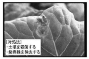
例えば、画像認識装置は、病気に罹った農作物の画像データからその病名を認識し、病名と対応付けて保持している対処法等の情報を撮像装置10へ返す。そして、例えば図22に示すように、撮像装置10の表示部115は対処法等の情報を表示する。また、画像認識装置は、食事の際に撮影した料理の画像データから料理を認識し、料理と対応付けて保持している、主食、主菜又は副菜等の種別やカロリー等の情報を撮像装置10へ返す。さらに、画像認識装置がユーザの食事についての履歴データを保持しておき、その内容に基づいて予め用意されたメッセージを返すようにしてもよい。また、ユーザの食事についての履歴データに応じて管理栄養士等が栄養指導をするといったサービスに用いることもできる。そして、例えば図23に示すように、撮像装置10の表示部115はカロリーと食事についてのアドバイスを表示する。本実施の形態では、画像認識の精度が上がるように撮影を支援するため、画像認識装置での認識処理がうまくいかずに撮影し直すようなことが減る。なお、ここで述べた画像認識装置の処理を撮像装置1が実施するようにしてもよい。
以上本技術の実施の形態を説明したが、本技術はこれに限定されるものではない。例えば、機能ブロック図は一例であって、必ずしも実際のプログラムモジュール構成と一致しない場合もある。また、処理フローについても、処理結果が変わらない限り、ステップの順番を入れ替えたり、並列実施するようにしてもよい。
本実施の形態に係る撮像装置1は、デジタルカメラ、デジタルビデオカメラ、カメラ付き携帯電話機、カメラを有しネットワーク接続可能な携帯情報端末、その他カメラと接続され又はカメラを内蔵したポータブルコンピュータ等、デジタルカメラとしての機能を有する携帯端末により実現される。また、そのような携帯端末を本実施の形態の撮像装置1又は撮像装置10として機能させるためのアプリケーションプログラムが提供されることもある。
また、本実施の形態では、撮像装置1の基準データ格納部109に基準ベクトルと基準距離とを格納しておく。これらを算出するために用いる画像のサンプル集合や参照特徴ベクトル等は格納していないため、撮像装置1が保持するデータ量は少なくて済む。ここで、基準データ格納部109に格納しておくデータは、撮像装置1が受信するなどして追加又は更新できるようにしてもよい。また、基準データを生成するための前処理を撮像装置1で行うようにすることもできる。
また、本実施の形態では、生成された画像データの特徴ベクトルから最も近い基準ベクトルに係るカテゴリを候補カテゴリと想定するようにしている。従って、ユーザは特別な設定をすることなく撮像装置1を使用することができる。ただし、「料理」若しくは「主菜」等、又は「農作物の病気」若しくは「キャベツの病気」等のように、ユーザが被写体の属するカテゴリを絞るような設定をしてもよい。例えば、ユーザが撮影の前にカテゴリを選択して、撮像装置1が当該カテゴリを対象として本実施の形態に係る処理を行うようにすれば、当該カテゴリについての基準ベクトルに近づくようガイドすることができる。また、複数の小カテゴリを含む大カテゴリを選択するような選択手法を採用してもよい。このようにすることで、選択についてのユーザの負担を軽くすることができ、さらに認識精度を向上させることができる。より具体的には、全く異なるカテゴリであるが基準ベクトルが近いカテゴリとして認識されることを避けることができる。なお、ユーザからカテゴリの選択を受け付けた後に、撮像装置1が、選択されたカテゴリについての基準ベクトル等のデータを画像認識装置等からダウンロードするようにしてもよい。
採用する特徴ベクトルについても、色についての特徴ベクトルには限定されない。テクスチャを表す特徴ベクトルや、局所記述子による特徴ベクトル等、模様や形状についての特徴ベクトルを採用することもできる。また、色の特徴ベクトルであっても、RGBでなく所定の色のヒストグラムを用いるようにしてもよい。さらに、複数の特徴量を組み合わせて判断するようにしてもよい。
さらに、図13に示したガイド情報も一例である。円やバー以外の図形を用いてもよいし、「適切な撮影位置」、「適切な撮影位置に近づいている」又は「適切な撮影位置に近づいていない」のように文字によるガイド情報を表示してもよい。塗りつぶしに用いられる色は、他の色の組み合わせを用いてもよいし、一色であってもよい。また、例えばバーに目盛を入れる等により換算率の基準がわかるようにしておき、距離の大きさに応じて換算率が適宜変更されるようにしてもよい。さらに、領域1007には、ベクトル間の距離に基づくガイド情報を表示するのではなく、被写体と撮像装置1との現実の位置関係に基づくガイド情報を表示するようにしてもよい。例えば、適切な撮影位置に近づいたときの撮像装置1の動きをセンサ等で取得しておき、撮像装置1をどのように動かすべきかガイドする。
なお、上で述べた前処理を行うコンピュータ及び画像認識装置は、コンピュータ装置であって、図24に示すように、メモリ2501とCPU2503とハードディスク・ドライブ(HDD)2505と表示装置2509に接続される表示制御部2507とリムーバブル・ディスク2511用のドライブ装置2513と入力装置2515とネットワークに接続するための通信制御部2517とがバス2519で接続されている。オペレーティング・システム(OS:Operating System)及び本実施例における処理を実施するためのアプリケーション・プログラムは、HDD2505に格納されており、CPU2503により実行される際にはHDD2505からメモリ2501に読み出される。CPU2503は、アプリケーション・プログラムの処理内容に応じて表示制御部2507、通信制御部2517、ドライブ装置2513を制御して、所定の動作を行わせる。また、処理途中のデータについては、主としてメモリ2501に格納されるが、HDD2505に格納されるようにしてもよい。本技術の実施例では、上で述べた処理を実施するためのアプリケーション・プログラムはコンピュータ読み取り可能なリムーバブル・ディスク2511に格納されて頒布され、ドライブ装置2513からHDD2505にインストールされる。インターネットなどのネットワーク及び通信制御部2517を経由して、HDD2505にインストールされる場合もある。このようなコンピュータ装置は、上で述べたCPU2503、メモリ2501などのハードウエアとOS及びアプリケーション・プログラムなどのプログラムとが有機的に協働することにより、上で述べたような各種機能を実現する。なお、撮像装置1又は撮像装置10も、このようなコンピュータ装置にレンズ及び撮像素子を含む撮像部を設けたものである場合がある。
以上述べた本実施の形態をまとめると、以下のようになる。
本実施の形態に係る撮像装置は、(A)画像データを生成し、データ格納部に格納する撮像部と、(B)データ格納部に格納された画像データから画像の特徴を表す特徴ベクトルを抽出し、特徴ベクトル格納部に格納する特徴ベクトル抽出部と、(C)画像の特徴についての基準となる基準ベクトルを格納している基準ベクトル格納部と、(D)特徴ベクトル格納部に格納され且つ第1の時刻に生成された第1の画像データに係る特徴ベクトルと基準ベクトル格納部に格納されている基準ベクトルとの第1の距離と、特徴ベクトル格納部に格納され且つ第1の時刻より前の第2の時刻に生成された第2の画像データに係る特徴ベクトルと基準ベクトル格納部に格納されている基準ベクトルとの第2の距離とを比較することで、撮像部が生成した画像データが基準ベクトルに相当する画像データに近づいているか否かを判定する判定部と、(E)判定部の判定結果を表示する表示部とを有する。
特徴ベクトルは、被写体が同一であっても画像における被写体の位置や大きさ等、すなわち構図によって変化する場合がある。従って、特徴ベクトルを用いた画像認識を行う場合には、構図が、基準ベクトルに相当する画像における構図と同様になることが好ましい。上で述べたような構成であれば、表示部に、前よりも基準ベクトルに相当する画像データに近づいているか否かが表示されるため、ユーザが撮影しようとしている画像の構図を適切な構図へと導くことができるようになる。すなわち、特徴ベクトルを用いた画像認識において認識精度が向上するような画像の撮影を支援することができる。
また、基準ベクトル格納部が、(C1)基準ベクトルからの所定の距離として表される閾値をさらに格納しているようにしてもよい。そして、判定部は、(D1)第1の距離が基準ベクトル格納部に格納されている閾値よりも小さい場合、第1の画像データを予め定められた適切な状態であるとさらに判定するようにしてもよい。第1の距離が閾値よりも小さい場合、ユーザが撮影しようとしている画像の構図が基準ベクトルに相当する画像における構図に所定の基準以上近づいたといえる。このような場合に、第1の画像データを予め定められた適切な状態であるとさらに判定し、判定結果を表示すれば、ユーザは撮影してもよいことがわかる。
そして、基準ベクトル格納部が、(C2)複数の基準ベクトルを格納しているようにしてもよい。そして、判定部は、複数の基準ベクトルを用いて求められた複数の第1の距離と複数の第2の距離とのうち、第1の距離の最小値と第2の距離の最小値とを用いて判定を行うようにしてもよい。複数の基準ベクトルを格納しておくことで、複数種類の画像データを識別することができる。また、第1の距離の最小値及び第2の距離の最小値を自動的に選択して用いれば、ユーザは撮影しようとしている画像の種類を意識することなく、また、複数の基準ベクトルに相当する画像についての好ましい構図を理解することなく、本撮像装置を使用することができる。
さらに、(C3)基準ベクトルは、カテゴリ毎に用意され、当該カテゴリに属する各画像の画像データについて抽出される特徴ベクトルの重心ベクトルであってもよい。このようにすれば、認識精度が向上するか否かを、カテゴリ毎に用意された画像の集合に係る重心ベクトルに基づいて正確に判定できる。
また、判定部は、(D2)第1の画像データに係る特徴ベクトルと基準ベクトルとの距離の大きさを表す距離データを生成するようにし、表示部は、(E1)生成した距離データをさらに表示するようにしてもよい。距離データは、例えば、距離に応じて長さが伸縮するバーや、数値である。このようにすれば、ユーザは距離の大きさを直感的又は数量的に把握することができる。
なお、上記方法による処理をコンピュータに行わせるためのプログラムを作成することができ、当該プログラムは、例えばフレキシブルディスク、CD-ROM、光磁気ディスク、半導体メモリ、ハードディスク等のコンピュータ読み取り可能な記憶媒体又は記憶装置に格納される。尚、中間的な処理結果はメインメモリ等の記憶装置に一時保管される。
Claims (13)
- 画像データを生成し、データ格納部に格納する撮像部と、
前記データ格納部に格納された前記画像データから画像の特徴を表す特徴ベクトルを抽出し、特徴ベクトル格納部に格納する特徴ベクトル抽出部と、
前記画像の特徴についての基準となる基準ベクトルを格納している基準ベクトル格納部と、
前記特徴ベクトル格納部に格納され且つ第1の時刻に生成された第1の画像データに係る特徴ベクトルと前記基準ベクトル格納部に格納されている前記基準ベクトルとの第1の距離と、前記特徴ベクトル格納部に格納され且つ前記第1の時刻より前の第2の時刻に生成された第2の画像データに係る特徴ベクトルと前記基準ベクトル格納部に格納されている前記基準ベクトルとの第2の距離とを比較することで、前記撮像部が生成した画像データが前記基準ベクトルに相当する画像データに近づいているか否かを判定する判定部と、
前記判定部の判定結果を表示する表示部と、
を有する撮像装置。 - 前記基準ベクトル格納部が、
前記基準ベクトルからの所定の距離として表される閾値をさらに格納しており、
前記判定部は、
前記第1の距離が前記基準ベクトル格納部に格納されている前記閾値よりも小さい場合、前記第1の画像データを予め定められた適切な状態であるとさらに判定する
請求項1記載の撮像装置。 - 前記基準ベクトル格納部が、
複数の基準ベクトルを格納しており、
前記判定部は、
前記複数の基準ベクトルを用いて求められた複数の第1の距離と複数の第2の距離とのうち、前記第1の距離の最小値と前記第2の距離の最小値とを用いて判定を行う
請求項1又は2記載の撮像装置。 - 前記基準ベクトルは、カテゴリ毎に用意され、当該カテゴリに属する各画像の画像データについて抽出される特徴ベクトルの重心ベクトルである
請求項1乃至3のいずれか1つ記載の撮像装置。 - 前記判定部は、
前記第1の画像データに係る特徴ベクトルと前記基準ベクトルとの距離の大きさを表す距離データを生成し、
前記表示部は、
生成した前記距離データをさらに表示する
請求項1乃至4のいずれか1つ記載の撮像装置。 - 撮像部により生成された画像データを格納しているデータ格納部に格納されており且つ第1の時刻に生成された画像データから画像の特徴を表す第1の特徴ベクトルを抽出して特徴ベクトル格納部に格納するステップと、
前記データ格納部に格納されており且つ前記第1の時刻より後の第2の時刻に生成された画像データから第2の特徴ベクトルを抽出して前記特徴ベクトル格納部に格納するステップと、
前記特徴ベクトル格納部に格納された第1の特徴ベクトルと前記画像の特徴についての基準となる基準ベクトルを格納している基準ベクトル格納部に格納されている前記基準ベクトルとの第1の距離と、前記特徴ベクトル格納部に格納された第2の特徴ベクトルと前記基準ベクトル格納部に格納されている前記基準ベクトルとの第2の距離とを比較することで、前記撮像部により生成された画像データが前記基準ベクトルに相当する画像データに近づいているか否かを判定する判定ステップと、
前記判定ステップにおける判定結果を表示部に表示するステップと、
をコンピュータに実行させるためのプログラム。 - 前記基準ベクトル格納部が、
前記基準ベクトルからの所定の距離として表される閾値をさらに格納しており、
前記判定ステップにおいて、
前記第1の距離が前記基準ベクトル格納部に格納されている前記閾値よりも小さい場合、前記第1の画像データを予め定められた適切な状態であるとさらに判定する
請求項6記載のプログラム。 - 前記基準ベクトル格納部が、
複数の基準ベクトルを格納しており、
前記判定ステップにおいて、
前記複数の基準ベクトルを用いて求められた複数の第1の距離と複数の第2の距離とのうち、前記第1の距離の最小値と前記第2の距離の最小値とを用いて判定を行う
請求項6又は7記載のプログラム。 - 前記判定ステップにおいて、
前記第1の画像データに係る特徴ベクトルと前記基準ベクトルとの距離の大きさを表す距離データを生成し、
前記表示部は、
生成した前記距離データをさらに表示する
請求項6乃至8のいずれか1つ記載のプログラム。 - 撮像部により生成された画像データを格納しているデータ格納部に格納されており且つ第1の時刻に生成された画像データから画像の特徴を表す第1の特徴ベクトルを抽出して特徴ベクトル格納部に格納するステップと、
前記データ格納部に格納されており且つ前記第1の時刻より後の第2の時刻に生成された画像データから第2の特徴ベクトルを抽出して前記特徴ベクトル格納部に格納するステップと、
前記特徴ベクトル格納部に格納された第1の特徴ベクトルと前記画像の特徴についての基準となる基準ベクトルを格納している基準ベクトル格納部に格納されている前記基準ベクトルとの第1の距離と、前記特徴ベクトル格納部に格納された第2の特徴ベクトルと前記基準ベクトル格納部に格納されている前記基準ベクトルとの第2の距離とを比較することで、前記撮像部により生成された画像データが前記基準ベクトルに相当する画像データに近づいているか否かを判定する判定ステップと、
前記判定ステップにおける判定結果を表示部に表示するステップと、
を含み、コンピュータに実行される撮像支援方法。 - 前記基準ベクトル格納部が、
前記基準ベクトルからの所定の距離として表される閾値をさらに格納しており、
前記判定ステップにおいて、
前記第1の距離が前記基準ベクトル格納部に格納されている前記閾値よりも小さい場合、前記第1の画像データを予め定められた適切な状態であるとさらに判定する
請求項10記載の撮像支援方法。 - 前記基準ベクトル格納部が、
複数の基準ベクトルを格納しており、
前記判定ステップにおいて、
前記複数の基準ベクトルを用いて求められた複数の第1の距離と複数の第2の距離とのうち、前記第1の距離の最小値と前記第2の距離の最小値とを用いて判定を行う
請求項10又は11記載の撮像支援方法。 - 前記判定ステップにおいて、
前記第1の画像データに係る特徴ベクトルと前記基準ベクトルとの距離の大きさを表す距離データを生成し、
前記表示部は、
生成した前記距離データをさらに表示する
請求項10乃至12のいずれか1つ記載の撮像支援方法。
Priority Applications (2)
| Application Number | Priority Date | Filing Date | Title |
|---|---|---|---|
| PCT/JP2011/053923 WO2012114464A1 (ja) | 2011-02-23 | 2011-02-23 | 撮像装置、プログラム及び撮像支援方法 |
| JP2013500760A JP5626444B2 (ja) | 2011-02-23 | 2011-02-23 | 撮像装置、プログラム及び撮像支援方法 |
Applications Claiming Priority (1)
| Application Number | Priority Date | Filing Date | Title |
|---|---|---|---|
| PCT/JP2011/053923 WO2012114464A1 (ja) | 2011-02-23 | 2011-02-23 | 撮像装置、プログラム及び撮像支援方法 |
Publications (1)
| Publication Number | Publication Date |
|---|---|
| WO2012114464A1 true WO2012114464A1 (ja) | 2012-08-30 |
Family
ID=46720284
Family Applications (1)
| Application Number | Title | Priority Date | Filing Date |
|---|---|---|---|
| PCT/JP2011/053923 Ceased WO2012114464A1 (ja) | 2011-02-23 | 2011-02-23 | 撮像装置、プログラム及び撮像支援方法 |
Country Status (2)
| Country | Link |
|---|---|
| JP (1) | JP5626444B2 (ja) |
| WO (1) | WO2012114464A1 (ja) |
Cited By (2)
| Publication number | Priority date | Publication date | Assignee | Title |
|---|---|---|---|---|
| CN111639667A (zh) * | 2020-04-14 | 2020-09-08 | 北京迈格威科技有限公司 | 图像识别方法、装置、电子设备及计算机可读存储介质 |
| JP2025044231A (ja) * | 2023-09-19 | 2025-04-01 | ソフトバンクグループ株式会社 | システム |
Citations (3)
| Publication number | Priority date | Publication date | Assignee | Title |
|---|---|---|---|---|
| JP2004133567A (ja) * | 2002-10-09 | 2004-04-30 | Hitachi Ltd | 移動体およびその位置検出装置 |
| JP2007233247A (ja) * | 2006-03-03 | 2007-09-13 | Fujifilm Corp | 焦点調節量決定装置、方法、およびプログラム、ならびに撮像装置 |
| JP2009521134A (ja) * | 2005-12-22 | 2009-05-28 | オリンパス株式会社 | シーン認識撮影システム及びシーン認識撮影方法 |
-
2011
- 2011-02-23 JP JP2013500760A patent/JP5626444B2/ja not_active Expired - Fee Related
- 2011-02-23 WO PCT/JP2011/053923 patent/WO2012114464A1/ja not_active Ceased
Patent Citations (3)
| Publication number | Priority date | Publication date | Assignee | Title |
|---|---|---|---|---|
| JP2004133567A (ja) * | 2002-10-09 | 2004-04-30 | Hitachi Ltd | 移動体およびその位置検出装置 |
| JP2009521134A (ja) * | 2005-12-22 | 2009-05-28 | オリンパス株式会社 | シーン認識撮影システム及びシーン認識撮影方法 |
| JP2007233247A (ja) * | 2006-03-03 | 2007-09-13 | Fujifilm Corp | 焦点調節量決定装置、方法、およびプログラム、ならびに撮像装置 |
Cited By (3)
| Publication number | Priority date | Publication date | Assignee | Title |
|---|---|---|---|---|
| CN111639667A (zh) * | 2020-04-14 | 2020-09-08 | 北京迈格威科技有限公司 | 图像识别方法、装置、电子设备及计算机可读存储介质 |
| CN111639667B (zh) * | 2020-04-14 | 2023-06-16 | 北京迈格威科技有限公司 | 图像识别方法、装置、电子设备及计算机可读存储介质 |
| JP2025044231A (ja) * | 2023-09-19 | 2025-04-01 | ソフトバンクグループ株式会社 | システム |
Also Published As
| Publication number | Publication date |
|---|---|
| JP5626444B2 (ja) | 2014-11-19 |
| JPWO2012114464A1 (ja) | 2014-07-07 |
Similar Documents
| Publication | Publication Date | Title |
|---|---|---|
| US9367746B2 (en) | Image processing apparatus for specifying an image relating to a predetermined moment from among a plurality of images | |
| JP4772839B2 (ja) | 画像識別方法および撮像装置 | |
| JP5293206B2 (ja) | 画像検索装置、画像検索方法及びプログラム | |
| KR20090087670A (ko) | 촬영 정보 자동 추출 시스템 및 방법 | |
| JP2012528506A (ja) | 背景から前景の頭頂部を分離するための方法および装置 | |
| CN112368724A (zh) | 学习装置、学习系统以及学习方法 | |
| JP2021105850A (ja) | 画像処理装置及び方法、及び撮像装置 | |
| JP2008217702A (ja) | 撮影装置および撮影方法 | |
| JP5862071B2 (ja) | 画像処理装置、撮像装置およびプログラム | |
| CN112887610A (zh) | 拍摄方法、装置、电子设备及存储介质 | |
| JP2012105205A (ja) | キーフレーム抽出装置、キーフレーム抽出プログラム、キーフレーム抽出方法、撮像装置、およびサーバ装置 | |
| US10212363B2 (en) | Picture processing method and electronic device | |
| JP2003288601A (ja) | 画像撮像装置、画像処理装置、画像処理方法及び画像情報分類サービス方法 | |
| CN110149475B (zh) | 图像拍摄方法及装置、电子装置、存储介质和计算机设备 | |
| JP5626444B2 (ja) | 撮像装置、プログラム及び撮像支援方法 | |
| KR20140061226A (ko) | 영상을 표시하는 방법 및 이를 위한 장치 | |
| KR20180075506A (ko) | 정보 처리 장치, 정보 처리 방법 및 프로그램 | |
| JP2011193066A (ja) | 撮像装置 | |
| CN114025100A (zh) | 拍摄方法、装置、电子设备和可读存储介质 | |
| JP5972947B2 (ja) | ユーザの撮影を支援する方法、携帯式電子機器およびコンピュータ・プログラム | |
| CN113840080B (zh) | 摄像设备、摄像设备的控制方法和计算机可读介质 | |
| WO2019215797A1 (ja) | 構図アドバイスシステム、構図アドバイス方法、カメラ、プログラム | |
| JP5181935B2 (ja) | 画像処理装置、プログラム及び被写体検出方法 | |
| JP2022003757A (ja) | 撮像装置、撮像装置の制御方法及びプログラム | |
| JP5677080B2 (ja) | 画像処理装置およびその制御方法 |
Legal Events
| Date | Code | Title | Description |
|---|---|---|---|
| 121 | Ep: the epo has been informed by wipo that ep was designated in this application |
Ref document number: 11859213 Country of ref document: EP Kind code of ref document: A1 |
|
| ENP | Entry into the national phase |
Ref document number: 2013500760 Country of ref document: JP Kind code of ref document: A |
|
| NENP | Non-entry into the national phase |
Ref country code: DE |
|
| 122 | Ep: pct application non-entry in european phase |
Ref document number: 11859213 Country of ref document: EP Kind code of ref document: A1 |