WO2012111830A1 - パーキングブレーキ装置 - Google Patents
パーキングブレーキ装置 Download PDFInfo
- Publication number
- WO2012111830A1 WO2012111830A1 PCT/JP2012/053886 JP2012053886W WO2012111830A1 WO 2012111830 A1 WO2012111830 A1 WO 2012111830A1 JP 2012053886 W JP2012053886 W JP 2012053886W WO 2012111830 A1 WO2012111830 A1 WO 2012111830A1
- Authority
- WO
- WIPO (PCT)
- Prior art keywords
- rod
- parking
- service
- chamber
- spring
- Prior art date
- Legal status (The legal status is an assumption and is not a legal conclusion. Google has not performed a legal analysis and makes no representation as to the accuracy of the status listed.)
- Ceased
Links
Images




Classifications
-
- B—PERFORMING OPERATIONS; TRANSPORTING
- B61—RAILWAYS
- B61H—BRAKES OR OTHER RETARDING DEVICES SPECIALLY ADAPTED FOR RAIL VEHICLES; ARRANGEMENT OR DISPOSITION THEREOF IN RAIL VEHICLES
- B61H5/00—Applications or arrangements of brakes with substantially radial braking surfaces pressed together in axial direction, e.g. disc brakes
-
- F—MECHANICAL ENGINEERING; LIGHTING; HEATING; WEAPONS; BLASTING
- F16—ENGINEERING ELEMENTS AND UNITS; GENERAL MEASURES FOR PRODUCING AND MAINTAINING EFFECTIVE FUNCTIONING OF MACHINES OR INSTALLATIONS; THERMAL INSULATION IN GENERAL
- F16D—COUPLINGS FOR TRANSMITTING ROTATION; CLUTCHES; BRAKES
- F16D55/00—Brakes with substantially-radial braking surfaces pressed together in axial direction, e.g. disc brakes
- F16D55/02—Brakes with substantially-radial braking surfaces pressed together in axial direction, e.g. disc brakes with axially-movable discs or pads pressed against axially-located rotating members
- F16D55/22—Brakes with substantially-radial braking surfaces pressed together in axial direction, e.g. disc brakes with axially-movable discs or pads pressed against axially-located rotating members by clamping an axially-located rotating disc between movable braking members, e.g. movable brake discs or brake pads
- F16D55/224—Brakes with substantially-radial braking surfaces pressed together in axial direction, e.g. disc brakes with axially-movable discs or pads pressed against axially-located rotating members by clamping an axially-located rotating disc between movable braking members, e.g. movable brake discs or brake pads with a common actuating member for the braking members
- F16D55/2245—Brakes with substantially-radial braking surfaces pressed together in axial direction, e.g. disc brakes with axially-movable discs or pads pressed against axially-located rotating members by clamping an axially-located rotating disc between movable braking members, e.g. movable brake discs or brake pads with a common actuating member for the braking members in which the common actuating member acts on two levers carrying the braking members, e.g. tong-type brakes
-
- F—MECHANICAL ENGINEERING; LIGHTING; HEATING; WEAPONS; BLASTING
- F16—ENGINEERING ELEMENTS AND UNITS; GENERAL MEASURES FOR PRODUCING AND MAINTAINING EFFECTIVE FUNCTIONING OF MACHINES OR INSTALLATIONS; THERMAL INSULATION IN GENERAL
- F16D—COUPLINGS FOR TRANSMITTING ROTATION; CLUTCHES; BRAKES
- F16D2121/00—Type of actuator operation force
- F16D2121/02—Fluid pressure
- F16D2121/04—Fluid pressure acting on a piston-type actuator, e.g. for liquid pressure
-
- F—MECHANICAL ENGINEERING; LIGHTING; HEATING; WEAPONS; BLASTING
- F16—ENGINEERING ELEMENTS AND UNITS; GENERAL MEASURES FOR PRODUCING AND MAINTAINING EFFECTIVE FUNCTIONING OF MACHINES OR INSTALLATIONS; THERMAL INSULATION IN GENERAL
- F16D—COUPLINGS FOR TRANSMITTING ROTATION; CLUTCHES; BRAKES
- F16D2121/00—Type of actuator operation force
- F16D2121/02—Fluid pressure
- F16D2121/04—Fluid pressure acting on a piston-type actuator, e.g. for liquid pressure
- F16D2121/06—Fluid pressure acting on a piston-type actuator, e.g. for liquid pressure for releasing a normally applied brake
-
- F—MECHANICAL ENGINEERING; LIGHTING; HEATING; WEAPONS; BLASTING
- F16—ENGINEERING ELEMENTS AND UNITS; GENERAL MEASURES FOR PRODUCING AND MAINTAINING EFFECTIVE FUNCTIONING OF MACHINES OR INSTALLATIONS; THERMAL INSULATION IN GENERAL
- F16D—COUPLINGS FOR TRANSMITTING ROTATION; CLUTCHES; BRAKES
- F16D2123/00—Multiple operation forces
-
- F—MECHANICAL ENGINEERING; LIGHTING; HEATING; WEAPONS; BLASTING
- F16—ENGINEERING ELEMENTS AND UNITS; GENERAL MEASURES FOR PRODUCING AND MAINTAINING EFFECTIVE FUNCTIONING OF MACHINES OR INSTALLATIONS; THERMAL INSULATION IN GENERAL
- F16D—COUPLINGS FOR TRANSMITTING ROTATION; CLUTCHES; BRAKES
- F16D2125/00—Components of actuators
- F16D2125/18—Mechanical mechanisms
- F16D2125/58—Mechanical mechanisms transmitting linear movement
- F16D2125/64—Levers
-
- F—MECHANICAL ENGINEERING; LIGHTING; HEATING; WEAPONS; BLASTING
- F16—ENGINEERING ELEMENTS AND UNITS; GENERAL MEASURES FOR PRODUCING AND MAINTAINING EFFECTIVE FUNCTIONING OF MACHINES OR INSTALLATIONS; THERMAL INSULATION IN GENERAL
- F16D—COUPLINGS FOR TRANSMITTING ROTATION; CLUTCHES; BRAKES
- F16D2125/00—Components of actuators
- F16D2125/18—Mechanical mechanisms
- F16D2125/58—Mechanical mechanisms transmitting linear movement
- F16D2125/66—Wedges
-
- F—MECHANICAL ENGINEERING; LIGHTING; HEATING; WEAPONS; BLASTING
- F16—ENGINEERING ELEMENTS AND UNITS; GENERAL MEASURES FOR PRODUCING AND MAINTAINING EFFECTIVE FUNCTIONING OF MACHINES OR INSTALLATIONS; THERMAL INSULATION IN GENERAL
- F16D—COUPLINGS FOR TRANSMITTING ROTATION; CLUTCHES; BRAKES
- F16D2125/00—Components of actuators
- F16D2125/18—Mechanical mechanisms
- F16D2125/58—Mechanical mechanisms transmitting linear movement
- F16D2125/70—Rods
Definitions
- the present invention relates to a parking brake device for a railway vehicle disc brake (hereinafter referred to as a lever-type caliper brake), and more particularly to a parking brake device having a parking brake manual release mechanism in maintenance work or the like.
- this parking brake device is “a brake cylinder device used in a brake mechanism for a vehicle, in which the biasing force of the first spring 101 and the pressure of the first pressure chamber 102 act in opposite directions. 103, and the pressure fluid is supplied to the first pressure chamber 102, whereby the first piston 103 moves relative to the cylinder body 104 against the urging force of the first spring 101 to act as a brake.
- Service brake means that moves in the direction, the push rod 105 that can move with the first piston 103, and the push rod 105 that can move with the push rod 105 and moves in parallel with the movement direction of the first piston 103.
- the means 107 includes a concave portion or a convex portion provided in the guide member 106 and an engaging portion that engages with the concave portion or the convex portion.
- regulating means while being arranged between the serial first spring 101 restricts the movable range in the direction of movement of the first piston 103 of the guide member 106, and wherein the "which comprises a.
- a manual release mechanism 111 for manually releasing the brake operation state is provided in the spring brake means.
- an object of the present invention is to provide a parking brake device that simplifies the structure by adopting a clamp mechanism using an elastic body and can manually release a brake operation state with a one-touch type.
- a service rod is provided on a piston on the service chamber side that constitutes the parking brake device, and a parking rod is provided on a piston on the parking chamber side that is disposed to face the service chamber side.
- a parking rod is one in which one of the rods is slidably inserted into a guide formed on the other rod, and a step is provided at the end of the rod on the side inserted into the guide.
- a parking brake device in which an elastic body to be joined is provided on a rod having the guide, and both rods are connected and released by the elastic body.
- the parking brake device having the configuration of (1), wherein the elastic body is provided on an outer periphery of a rod having a locking portion.
- the guide is a cylindrical portion formed on one of the rods, and a telescopic shape is formed in the cylindrical portion formed on the rod.
- a step is provided at one end of the rod on the service chamber side or the parking chamber side, the one rod is inserted into a guide formed on the other rod, and an elastic body (
- the brake operating state can be easily released manually by a one-touch type.
- the rod on one side can be easily separated by sandwiching and expanding the elastic body (clip) provided on the other side by hand.
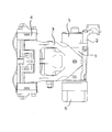
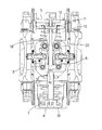
- FIG. 1 is a plan view of a lever-type caliper brake according to an embodiment of the present invention as viewed from the brake pad side.
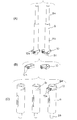
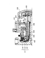
- FIG. 2 is a side view of FIG. 3 is a cross-sectional view taken along the line AA in FIG. 4A is a perspective view of the service rod
- FIG. 4B is a perspective view of the elastic body
- FIG. 4C is a perspective view of the parking rod.
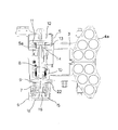
- FIG. 5 is a cross-sectional view taken along the line AA in FIG.
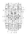
- FIG. 6 is a perspective view of a portion incorporating a manual release mechanism of the parking brake.
- FIG. 7 is a side view of FIG. 3 and is an assembly diagram for explaining the operation of the service rod and the parking rod.
- FIG. FIG. 8 is a view showing a state in which pressure is supplied to the service chamber from the state of FIG.
- FIG. 9 is a side view of FIG. 5, in which the pressure in the parking chamber is released, and the spring in the parking chamber moves the piston in the service chamber downward via the parking rod and the service rod, and the parking brake is activated.
- FIG. FIG. 10 is a view showing a state in which the parking rod and the service rod are disconnected.
- FIG. 11 is a sectional view of a parking apparatus for a conventional caliper brake.
- the lever-type caliper brake includes a body 1, a support 2, a lever portion 3, a pad holder 4, a pad assembly 4a, a service chamber 5, a parking chamber 6, a parking spring 7, a service rod 8, a parking rod 9,
- An elastic body (clip) 10 is provided, and the basic configuration is the same as that of a lever-type caliper brake having a conventional parking brake.
- the service chamber 5 constituting the parking brake device in the lever-type caliper brake will be described.
- the piston 11 that divides the chamber into two chambers, a pressure chamber 12 and a spring chamber 13, in the service chamber 5.
- the service rod 8 is attached to the piston 11 by a fixing means 14 such as a nut as will be described later.
- the service rod 8 is composed of a rod having a small diameter portion 8a and a large diameter portion 8b, and a step 8c is formed at the lower end of the large diameter portion 8b.
- the step 8c is formed in a conical shape having a small diameter in the tip direction as shown in the figure, but it is not always necessary to be conical.
- an elastic body (clip) described later can be engaged with and released from the elastic body 10 described later, such as a pyramid shape. Any other shape can be used as long as the step 8c can be pushed into the large-diameter cylindrical portion (guide) 9a of the parking rod 9 while expanding 10.
- the service rod 8 having the above-mentioned shape has a structure in which the end of the small diameter portion 8a is fixed to the piston 11 by the fixing means (bolt / nut type fixing means in this example) 14 as described above.
- the service rod 8 is disposed to extend downward toward the parking chamber 6 through the spring chamber 13 in the service chamber 5, through the lower portion of the service chamber 5.
- a spring 5a is disposed between the washer provided in the spring chamber 13 and the piston 11, and the biasing force of the spring 5a urges the piston 11 upward in the figure. Yes.
- the service rod 8 is also urged upward by the spring 5a integrally with the piston 11 by the action of the spring 5a.
- a pressure source (not shown) is connected to the pressure chamber 12 of the service chamber 5, and when the pressure fluid is injected into the pressure chamber 12, the piston 11 resists the urging force of the spring 5 a. It is configured to move in the middle and lower direction.
- the elastic body (clip) 10 described above is provided by being fitted into a hole (locking portion) 9c formed on the outer periphery of the parking rod 9, as shown in FIG. 4B, and is inserted into the cylindrical portion 9a. It is configured as a member that engages with the step 8 c of the service rod 8, and a claw 10 a is formed on the elastic body 10, and the elastic body 10 is expanded and formed on the service rod 8 by pinching the claw 10 a.
- a clamp mechanism capable of releasing the engagement with the step 8c is configured.
- the parking rod 9 has an end of a small-diameter rod 9b fixed to a piston 15 by a fixing means 16 such as a nut, and the large-diameter cylindrical portion 9a passes through a spring chamber 17 of the parking chamber 6 and passes through the parking chamber. And extended to the service chamber 5 side (upward in the figure).
- the large-diameter cylindrical portion 9a of the parking rod 9 is inserted with the large-diameter portion 8b of the service rod 8 described above, and both the rods can be telescopically expanded and contracted.
- the step 8c is locked by the elastic body 10 so as not to come out.
- a parking spring 7 for biasing the piston 15 downward in the figure is arranged in the spring chamber 17 of the parking chamber 6, and the piston 15 is always biased downward in the figure by the parking spring 7. For this reason, the parking rod 9 is also urged downward in the figure together with the piston 15 by the parking spring 7.
- the spring 5a (referred to as the first spring) provided in the service chamber 5 and the parking spring 7 (referred to as the second spring) provided in the parking chamber 6 have a spring strength,
- the relationship is “second spring> first spring”.
- the overall length when the service rod 8 and the parking rod 9 are connected by the elastic body 10 is the same as the piston in the service chamber 5 when the pressure in the parking chamber 6 is released and the perking brake is in operation.
- 11 is a length capable of bending the spring 5a to obtain a brake operating state.
- FIG. 7 that is, when the service rod 8 and the parking rod 9 are connected by the elastic body 10 and pressure fluid is supplied into the pressure chamber 18 of the parking chamber 6
- the piston 15 in the parking chamber 6 moves upward in the drawing while bending the parking spring (second spring) 7.
- the parking rod 9 also moves upward.
- the service rod 8 is also moved upward by the action of the spring (first spring) 5a in the service chamber 5, and maintains the state shown in the figure (brake release state). In this state, when pressure fluid is supplied to the pressure chamber 12 in the service chamber 5 (see FIG.
- the piston 11 in the service chamber 5 moves downward in the figure and is further fixed to the piston 11.
- the service rod 8 also moves downward, and the step 8c is pushed into the large-diameter cylindrical portion 9a of the parking rod 9, and this movement activates the lever portion 3 via the wedge 19 and the link mechanism 21 to apply the brake.
- the service brake is activated.
- the pressure in the service chamber 5 is released, the state returns to the state shown in FIG. 7 and the brake is released.
- the conical step 8c of the service rod 8 is elastic when the service brake is operated from the state where they are separated, that is, from the state shown in FIG.
- the body 10 is expanded to get over the elastic body and inserted again into the parking rod 9, and both are returned to the connected state by the elastic body 10 and the brake is activated.
- the service rod 8 is inserted into the large-diameter cylindrical portion 9a of the parking rod 9 as a guide structure in which the service rod 8 and the parking rod 9 extend and contract.
- a cylindrical portion having a large diameter may be formed on the rod side, and a step of the parking rod may enter the cylinder.
- it is possible to adopt other forms such as a form in which the other rod is inserted into one groove instead of a form in which the other rod is inserted into one cylindrical portion.
- the Example of this invention has been described, it can change suitably within the range of the meaning of this invention.
- the specifications described in the examples are merely examples in all respects and should not be interpreted in a limited manner. Further, this application is based on a Japanese patent application filed on Feb. 18, 2011 (Japanese Patent Application No. 2011-032921), the contents of which are incorporated herein by reference.
- the parking brake device of the present invention can be used in the field of vehicles equipped with a brake.
Landscapes
- Engineering & Computer Science (AREA)
- Mechanical Engineering (AREA)
- General Engineering & Computer Science (AREA)
- Braking Arrangements (AREA)
Abstract
パーキングブレーキ装置を構成するサービスチャンバ側のピストンに設けたサービスロッド8とパーキングチャンバ側のピストンに設けたパーキングロッド9とは、いずれか一方のロッドが他方のロッドに形成したガイドに摺動可能に挿入され、かつ、前記ガイドに挿入される側のロッドの端部に設けられた段差8aに係合する弾性体10が前記ガイドを有するロッドに設けられ、前記弾性体10により双方のロッドが、ワンタッチで連結、解除される。
Description
本発明は、鉄道車両用ディスクブレーキ(以下、テコ式キャリパブレーキと云う)のパーキングブレーキ装置に関するものであり、特に保守作業などにおけるパーキングブレーキ手動解除機構を有するパーキングブレーキ装置に関するものである。
従来のテコ式キャリパブレーキのパーキング装置は保守点検作業時など、スプリングチャンバーを解除して作業を行なう場合、スプリングチャンバーを構成するネジを回転させてスプリングを緩める等の作業が必要であった。こうしたスプリングチャンバー解除方式を採用しているテコ式キャリパブレーキのパーキング装置の一例について図11を参照して説明する(特許文献1)。
図11において、このパーキングブレーキ装置は「車両用のブレーキ機構において用いられるブレーキシリンダ装置であって、第1バネ101の付勢力と第1圧力室102の圧力とが逆方向に作用する第1ピストン103を有し、前記第1圧力室102に圧力流体が供給されることにより前記第1バネ101の付勢力に抗して前記第1ピストン103がシリンダ本体104に対して相対移動してブレーキ作動方向に移動する常用ブレーキ手段と、前記第1ピストン103とともに移動可能な押棒105と、前記押棒105とともに移動可能であって前記押棒105が前記第1ピストン103の移動方向と平行に相対移動する際に所定の抵抗力が作用するように前記押棒105に取り付けられているガイド部材106を有し、ブレーキ解除時の前記第1ピストン103の移動方向における前記押棒105の前記シリンダ本体104からの突出長さをブレーキ作動の際に調整する突出長さ調整手段107と、第2バネ108の付勢力と第2圧力室109の圧力とが逆方向に作用するとともに前記押棒105が貫通する第2ピストン110を有し、前記第2圧力室109に圧力流体が供給されている状態から排出される状態へと移行することで前記第2バネ108の付勢力により前記第2ピストン110が前記ブレーキ方向に移動するとともに前記常用ブレーキ手段を介して前記押棒105を付勢するバネブレーキ手段と、を備え、前記突出長さ調整手段107は、前記ガイド部材106に設けられた凹部又は凸部と、前記凹部又は凸部と係合する係合部を有し前記第2ピストン110と前記第1バネ101との間に配設されるとともに前記ガイド部材106の前記第1ピストン103の移動方向における可動範囲を規制する規制手段と、を備えていること」を特徴とする。
そして、上記パーキングブレーキ装置には、バネブレーキ手段の中にブレーキ作動状態を手動にて開放するための手動開放機構111が設けられている。この手動開放機構111は、固定用リング112、閉じ部材113、固定ロッド114、戻しバネ、操作用リングを備えており、図からも理解できるようにこの手動開放機構111は構成部品が多く、構成が複雑でありコストも高くなる等の問題点がある。
また、上記パーキングブレーキ装置では、スプリングチャンバーを後から設置することが困難であり、汎用性に乏しい等の問題がある。
そして、上記パーキングブレーキ装置には、バネブレーキ手段の中にブレーキ作動状態を手動にて開放するための手動開放機構111が設けられている。この手動開放機構111は、固定用リング112、閉じ部材113、固定ロッド114、戻しバネ、操作用リングを備えており、図からも理解できるようにこの手動開放機構111は構成部品が多く、構成が複雑でありコストも高くなる等の問題点がある。
また、上記パーキングブレーキ装置では、スプリングチャンバーを後から設置することが困難であり、汎用性に乏しい等の問題がある。
そこで、本発明は、弾性体を用いたクランプ機構を採用することにより、構造を簡略化しワンタッチ式でブレーキ作動状態を手動にて開放できるパーキングブレーキ装置を提供することを目的とする。
本発明の上記目的は、下記構成により達成することができる。
(1)パーキングブレーキ装置を構成するサービスチャンバ側のピストンにサービスロッドが設けられ、また、サービスチャンバ側と対向して配置されたパーキングチャンバ側のピストンにパーキングロッドが設けられ、前記サービスロッドと前記パーキングロッドとは、いずれか一方のロッドが他方のロッドに形成したガイドに摺動可能に挿入され、かつ、前記ガイドに挿入される側のロッドの端部に段差が設けられ、前記段差に係合する弾性体が前記ガイドを有するロッドに設けられ、前記弾性体により双方のロッドが、連結、解除されるようにしたパーキングブレーキ装置。
(2) 上記(1)の構成のパーキングブレーキ装置であって、前記弾性体が、係止部を有するロッドの外周に設けられたパーキングブレーキ装置。
(3) 上記(1)または(2)の構成のパーキングブレーキ装置であって、前記ガイドは、いずれか一方のロッドに形成した筒状部であり、このロッドに形成した筒状部内にテレスコピック状に他方のロッドが摺動可能に挿入されるパーキングブレーキ装置。
(1)パーキングブレーキ装置を構成するサービスチャンバ側のピストンにサービスロッドが設けられ、また、サービスチャンバ側と対向して配置されたパーキングチャンバ側のピストンにパーキングロッドが設けられ、前記サービスロッドと前記パーキングロッドとは、いずれか一方のロッドが他方のロッドに形成したガイドに摺動可能に挿入され、かつ、前記ガイドに挿入される側のロッドの端部に段差が設けられ、前記段差に係合する弾性体が前記ガイドを有するロッドに設けられ、前記弾性体により双方のロッドが、連結、解除されるようにしたパーキングブレーキ装置。
(2) 上記(1)の構成のパーキングブレーキ装置であって、前記弾性体が、係止部を有するロッドの外周に設けられたパーキングブレーキ装置。
(3) 上記(1)または(2)の構成のパーキングブレーキ装置であって、前記ガイドは、いずれか一方のロッドに形成した筒状部であり、このロッドに形成した筒状部内にテレスコピック状に他方のロッドが摺動可能に挿入されるパーキングブレーキ装置。
上記構成によれば、サービスチャンバ側、パーキングチャンバ側の何れか一方のロッド先端に段差を設け、他方のロッドに形成したガイドに前記一方のロッドを挿入し、他方のロッドに設けた弾性体(クリップ)によるクランプ機構により、双方のロッドを連結、解除できるようにすることにより、ワンタッチ式でブレーキ作動状態を手動にて容易に開放できる。
前記ワンタッチ式でブレーキ作動状態を解除するには、他方側に設けた弾性体(クリップ)を外部から手で挟み込み、拡張させることにより、一方側のロッドを容易に分離することができる。
前記ワンタッチ式でブレーキ作動状態を解除するには、他方側に設けた弾性体(クリップ)を外部から手で挟み込み、拡張させることにより、一方側のロッドを容易に分離することができる。
本発明は、パーキングブレーキ装置を構成するサービスチャンバ側のピストンに取り付けたサービスロッドと、サービスチャンバ側と対向して配置されたパーキングチャンバ側のパーキングロッドとが、いずれか一方のロッドが他方のロッドに形成したガイドに摺動可能に挿入され、かつ、前記ガイドに挿入される側のロッドの端部に段差が設けられ、前記段差に係合する弾性体が前記ガイドを有するロッドに設けられ、前記弾性体により双方のロッドが、連結、解除されるようにしている。
以下、本発明に係るテコ式キャリパブレーキのパーキングブレーキ装置の実施例を図面に基づいて説明する。
図1は本発明の一実施形態に係るテコ式キャリパブレーキをブレーキパッド側からみた平面図、図2は同側面図、図3は図1中のA-A断面図、図4(A)~図4(C)はサービスロッド、弾性体、パーキングロッドの斜視図である。
図1は本発明の一実施形態に係るテコ式キャリパブレーキをブレーキパッド側からみた平面図、図2は同側面図、図3は図1中のA-A断面図、図4(A)~図4(C)はサービスロッド、弾性体、パーキングロッドの斜視図である。
図1~図3においてテコ式キャリパブレーキは、ボディ1、サポート2、テコ部3、パッドホルダ4、パッドアッセンブリ4a、サービスチャンバ5、パーキングチャンバ6、パーキングスプリング7、サービスロッド8、パーキングロッド9、弾性体(クリップ)10を備えており、基本的な構成は従来のパーキングブレーキを備えたテコ式キャリパブレーキと同様である。
図3及び図5において、テコ式キャリパブレーキにおけるパーキングブレーキ装置を構成するサービスチャンバ5を説明すると、該サービスチャンバ5内には同チャンバを圧力室12とスプリング室13の二室に区画するピストン11が配置され、ピストン11には後述するようにサービスロッド8がナットなどの固定手段14により取り付けられている。
サービスロッド8は、図4(A)に示すように小径部8aと大径部8bとからなるロッドで構成されており、大径部8bの下端には段差8cが形成されている。この段差8cは本実施例では図示のように先端方向が小径となる円錐状に形成されているが、必ずしも円錐状である必要はない。例えば、角錐状など、後述する弾性体10と係止、解除でき、かつ、サービスロッド8を、後述するパーキングロッド9の大径の筒状部9aに押し込む際に、後述する弾性体(クリップ)10を拡開しながら段差8cをパーキングロッド9の大径の筒状部(ガイド)9aに押し込むことができる形状であれば、他の形状として形成することも可能である。
上記形状を有するサービスロッド8は、小径部8aの端部が前述したように固定手段(本例ではボルト・ナット式固定手段)14により前記ピストン11に固定される構造となっている。また、サービスロッド8は、サービスチャンバ5内のスプリング室13を通りサービスチャンバ5の下部を通って、パーキングチャンバ6に向けて下方に延長して配置されている。
サービスチャンバ5のスプリング室13には、前記スプリング室13に設けた座金と前記ピストン11との間にスプリング5aが配置され、このスプリング5aの付勢力によりピストン11を図中上方に付勢している。また、スプリング5aの作用により、サービスロッド8もピストン11と一体にスプリング5aにより上方に付勢されている。また、サービスチャンバ5の圧力室12には、図示せぬ圧力源が接続されており、圧力室12に圧力流体が注入されると、前記ピストン11が前記スプリング5aの付勢力に抗して図中下方に移動する構成となっている。
前述した弾性体(クリップ)10は、図4(B)に示すようにパーキングロッド9の外周に形成した孔(係止部)9cに嵌合して設けられ、筒状部9aに挿入されたサービスロッド8の段差8cに係合する部材として構成され、弾性体10には爪10aが形成され、この爪10aを摘んで挟むことにより、弾性体10を拡開させ、サービスロッド8に形成した段差8cとの係合を解除できるクランプ機構を構成するようになっている。
図3及び図5において、テコ式キャリパブレーキにおけるパーキングブレーキ装置を構成するパーキングチャンバ6を説明すると、パーキングチャンバ6は、サービスチャンバ5と同様にピストン15により圧力室18とスプリング室17の二室に区画され、ピストン15にはパーキングロッド9が適宜、固定手段(本例ではボルト・ナット式固定手段)16により取り付けられている。
パーキングロッド9は、図4(C)に示すように大径の筒状部9aと小径のロッド9bとから構成されており、大径の筒状部9aの端部には、前述の弾性体(クリップ)10が係止する孔(係止部)9cが構成されている。パーキングロッド9は、小径のロッド9bの端部がピストン15にナット等の固定手段16により固定されており、また、大径の筒状部9aは、パーキングチャンバ6のスプリング室17を通りパーキングチャンバの壁22を貫通してサービスチャンバ5側(図中上方)に延長して配置される。
パーキングロッド9は、図4(C)に示すように大径の筒状部9aと小径のロッド9bとから構成されており、大径の筒状部9aの端部には、前述の弾性体(クリップ)10が係止する孔(係止部)9cが構成されている。パーキングロッド9は、小径のロッド9bの端部がピストン15にナット等の固定手段16により固定されており、また、大径の筒状部9aは、パーキングチャンバ6のスプリング室17を通りパーキングチャンバの壁22を貫通してサービスチャンバ5側(図中上方)に延長して配置される。
パーキングロッド9の大径の筒状部9aには、前述したサービスロッド8の大径部8bが挿入され、両ロッドはテレスコピック状に伸縮できる構成となっており、パーキングロッド9からサービスロッド8が抜け出さないように段差8cが前記弾性体10により係止される構成となっている。パーキングチャンバ6のスプリング室17には、ピストン15を図中下方に付勢するパーキングスプリング7が配置され、ピストン15は常時このパーキングスプリング7により図中下方に付勢されている。このため、パーキングロッド9もこのパーキングスプリング7によりピストン15と一体になって図中下方に付勢されている。
なお、サービスチャンバ5内に設けるスプリング5a(第1スプリングという)とパーキングチャンバ6内に設けるパーキングスプリング7(第2スプリングという)とは、スプリングの強さが、
第2スプリング>第1スプリング
の関係となっている。
また、サービスロッド8とパーキングロッド9とが弾性体10によって連結された状態の時の全体の長さは、パーキングチャンバ6内の圧力を抜きパーキンブブレーキ作動状態の時に、サービスチャンバ5内のピストン11がスプリング5aを撓めてブレーキ作動状態を得ることができる長さとなっている。
なお、サービスチャンバ5内に設けるスプリング5a(第1スプリングという)とパーキングチャンバ6内に設けるパーキングスプリング7(第2スプリングという)とは、スプリングの強さが、
第2スプリング>第1スプリング
の関係となっている。
また、サービスロッド8とパーキングロッド9とが弾性体10によって連結された状態の時の全体の長さは、パーキングチャンバ6内の圧力を抜きパーキンブブレーキ作動状態の時に、サービスチャンバ5内のピストン11がスプリング5aを撓めてブレーキ作動状態を得ることができる長さとなっている。
図7において、前記サービスチャンバ5と前記パーキングチャンバ6との間には、図示するようにブレーキアーム作動用のリンク機構21等が配置されている。
この構成について図7を参照してさらに説明すると、サービスチャンバ5側に配置されたサービスロッド8の周囲にはウェッジ19が取り付けられており、このウェッジ19には対向する2個のローラ20が当接している。前記各ローラ20はリンク機構21に取り付けられており、リンク機構21は適宜連結手段(本実施例ではアジャスタ機構)を介して左右のテコ部3に連結されている。
なお、前記リンク機構21等は本願の要旨ではなく、また、公知のリンク機構(例えば、本出願人によって出願された日本国特開2010-65751を参照)を採用していることから詳細な説明は省略する。
この構成について図7を参照してさらに説明すると、サービスチャンバ5側に配置されたサービスロッド8の周囲にはウェッジ19が取り付けられており、このウェッジ19には対向する2個のローラ20が当接している。前記各ローラ20はリンク機構21に取り付けられており、リンク機構21は適宜連結手段(本実施例ではアジャスタ機構)を介して左右のテコ部3に連結されている。
なお、前記リンク機構21等は本願の要旨ではなく、また、公知のリンク機構(例えば、本出願人によって出願された日本国特開2010-65751を参照)を採用していることから詳細な説明は省略する。
上記構成のパーキングブレーキ装置の作動を説明する。
図7において(即ち、サービスロッド8とパーキングロッド9が弾性体10により連結されており、パーキングチャンバ6の圧力室18内に圧力流体が供給されている状態の時)、
パーキングチャンバ6の圧力室18内に圧力流体が供給された状態となっていると、パーキングチャンバ6内のピストン15がパーキングスプリング(第2スプリング)7を撓めながら、図中上方に移動する。この結果、パーキングロッド9も上方に移動する。さらに、サービスロッド8もサービスチャンバ5内のスプリング(第1スプリング)5aの作用により上方に移動し、図示の状態を維持する(ブレーキ開放状態)。
この状態の時に、サービスチャンバ5内の圧力室12に圧力流体が供給されると(図8参照)、サービスチャンバ5内のピストン11が図中下方に移動し、さらにピストン11に固定されているサービスロッド8も下方に移動して段差8cがパーキングロッド9の大径の筒状部9a内に押し込まれ、この動きによりウェッジ19、リンク機構21を介してテコ部3が作動してブレーキが掛かかりサービスブレーキ作動状態となる。また、サービスチャンバ5内の圧力を開放すると、図7の状態に戻りブレーキが開放される。
図7において(即ち、サービスロッド8とパーキングロッド9が弾性体10により連結されており、パーキングチャンバ6の圧力室18内に圧力流体が供給されている状態の時)、
パーキングチャンバ6の圧力室18内に圧力流体が供給された状態となっていると、パーキングチャンバ6内のピストン15がパーキングスプリング(第2スプリング)7を撓めながら、図中上方に移動する。この結果、パーキングロッド9も上方に移動する。さらに、サービスロッド8もサービスチャンバ5内のスプリング(第1スプリング)5aの作用により上方に移動し、図示の状態を維持する(ブレーキ開放状態)。
この状態の時に、サービスチャンバ5内の圧力室12に圧力流体が供給されると(図8参照)、サービスチャンバ5内のピストン11が図中下方に移動し、さらにピストン11に固定されているサービスロッド8も下方に移動して段差8cがパーキングロッド9の大径の筒状部9a内に押し込まれ、この動きによりウェッジ19、リンク機構21を介してテコ部3が作動してブレーキが掛かかりサービスブレーキ作動状態となる。また、サービスチャンバ5内の圧力を開放すると、図7の状態に戻りブレーキが開放される。
図9に示す状態の時(即ち、サービスロッド8とパーキングロッド9が弾性体10により連結されており、パーキングチャンバ6の圧力室18内の圧力が抜けている状態の時)、
サービスチャンバ5内のスプリング(第1スプリング)5aとパーキングチャンバ6内のパーキングスプリング(第2スプリング)7とが上記した関係にあるので、パーキングチャンバ6内のパーキングスプリング(第2スプリング)7の付勢力によりパーキングロッド9およびサービスロッド8を介してサービスチャンバ5内のピストン11がスプリング(第1スプリング)5aを変形させて図中下方に変位した状態となる。
この状態の時には、サービスロッド8が下方に引っ張られた状態となり、ウェッジ19、リンク機構21を介してテコ部3が作動してブレーキが掛かかりパーキングブレーキ作動状態となる。なお、この状態でサービスチャンバ5内の圧力室12に圧力が供給された場合、サービスブレーキが作動した状態となる。
サービスチャンバ5内のスプリング(第1スプリング)5aとパーキングチャンバ6内のパーキングスプリング(第2スプリング)7とが上記した関係にあるので、パーキングチャンバ6内のパーキングスプリング(第2スプリング)7の付勢力によりパーキングロッド9およびサービスロッド8を介してサービスチャンバ5内のピストン11がスプリング(第1スプリング)5aを変形させて図中下方に変位した状態となる。
この状態の時には、サービスロッド8が下方に引っ張られた状態となり、ウェッジ19、リンク機構21を介してテコ部3が作動してブレーキが掛かかりパーキングブレーキ作動状態となる。なお、この状態でサービスチャンバ5内の圧力室12に圧力が供給された場合、サービスブレーキが作動した状態となる。
図10に示す状態の時(パッド交換時など、パーキングチャンバ6内のスプリング力を解除したい時)、
この時には、弾性体10の爪10a(図4(B)、図6参照)を指等でつまんで、弾性体10を拡開するとサービスロッド8がスプリング5aの付勢力によって上方に、またパーキングロッド9がパーキングスプリング7の付勢力によって下方に移動して弾性体10との係合がはずれ、サービスロッド8の下端の段差8cがパーキングロッド9の大径の筒状部9a内から抜けだす。この結果、サービスロッド8とパーキングロッド9は互いの連結が解除され、ブレーキが開放状態となり、この状態で修理等を行なう。
修理が終了し、サービスロッド8とパーキングロッド9とを連結するには、両者が分離された状態、即ち、図10の状態からサービスブレーキを作動させるとサービスロッド8の円錐状の段差8cが弾性体10を拡開させながら弾性体を乗り越えパーキングロッド9内に再び挿入され、両者は弾性体10により連結状態に復帰するとともにブレーキが作動する。
この時には、弾性体10の爪10a(図4(B)、図6参照)を指等でつまんで、弾性体10を拡開するとサービスロッド8がスプリング5aの付勢力によって上方に、またパーキングロッド9がパーキングスプリング7の付勢力によって下方に移動して弾性体10との係合がはずれ、サービスロッド8の下端の段差8cがパーキングロッド9の大径の筒状部9a内から抜けだす。この結果、サービスロッド8とパーキングロッド9は互いの連結が解除され、ブレーキが開放状態となり、この状態で修理等を行なう。
修理が終了し、サービスロッド8とパーキングロッド9とを連結するには、両者が分離された状態、即ち、図10の状態からサービスブレーキを作動させるとサービスロッド8の円錐状の段差8cが弾性体10を拡開させながら弾性体を乗り越えパーキングロッド9内に再び挿入され、両者は弾性体10により連結状態に復帰するとともにブレーキが作動する。
以上のように本実施例によれば、サービスロッド8とパーキングロッド9を連結している弾性体10を操作するだけでサービスロッド8とパーキングロッド9との連結を解除することができ、パッド交換を容易に行なうことができる。
なお、本実施例ではサービスロッド8とパーキングロッド9とが伸縮するガイドの構成として、サービスロッド8がパーキングロッド9の大径の筒状部9a内に挿入される構成となっているが、サービスロッド側に大径の筒状部を形成し、その筒内にパーキングロッドの段差が入り込む構成とすることもできる。また、一方の筒状部内に他方のロッドを挿入する形式ではなく、一方の溝内に他方のロッドを挿入する形式など他の形式を採用することも可能である。
以上、本発明の実施例について説明してきたが、本発明の趣旨の範囲内で、適宜変更することができる。実施例に記載の諸元はあらゆる点で単なる例示に過ぎず限定的に解釈してはならない。
更に、本出願は、2011年2月18日出願の日本特許出願(特願2011-032921)に基づくものであり、その内容はここに参照として取り込まれる。
以上、本発明の実施例について説明してきたが、本発明の趣旨の範囲内で、適宜変更することができる。実施例に記載の諸元はあらゆる点で単なる例示に過ぎず限定的に解釈してはならない。
更に、本出願は、2011年2月18日出願の日本特許出願(特願2011-032921)に基づくものであり、その内容はここに参照として取り込まれる。
本発明のパーキングブレーキ装置は、ブレーキを搭載する車両分野に利用することができる。
1 ボディ
2 サポート
3 テコ部
4 パッドホルダ
5 サービスチャンバ
5a スプリング(第1スプリング)
6 パーキングチャンバ
7 パーキングスプリング(第2スプリング)
8 サービスロッド
8a 小径部
8b 大径部
8c 段差
9 パーキングロッド
9a 大径の筒状部(ガイド)
9b 小径のロッド
9c 孔(係止部)
10 弾性体(クリップ)
10a 爪
11 ピストン
12 圧力室
13 スプリング室
14 固定手段
15 ピストン
16 固定手段
17 スプリング室
18 圧力室
19 ウェッジ
20 ローラ
21 リンク
22 壁
2 サポート
3 テコ部
4 パッドホルダ
5 サービスチャンバ
5a スプリング(第1スプリング)
6 パーキングチャンバ
7 パーキングスプリング(第2スプリング)
8 サービスロッド
8a 小径部
8b 大径部
8c 段差
9 パーキングロッド
9a 大径の筒状部(ガイド)
9b 小径のロッド
9c 孔(係止部)
10 弾性体(クリップ)
10a 爪
11 ピストン
12 圧力室
13 スプリング室
14 固定手段
15 ピストン
16 固定手段
17 スプリング室
18 圧力室
19 ウェッジ
20 ローラ
21 リンク
22 壁
Claims (3)
- パーキングブレーキ装置を構成するサービスチャンバ側のピストンにサービスロッドが設けられ、また、サービスチャンバ側と対向して配置されたパーキングチャンバ側のピストンにパーキングロッドが設けられ、前記サービスロッドと前記パーキングロッドとは、いずれか一方のロッドが他方のロッドに形成したガイドに摺動可能に挿入され、かつ、前記ガイドに挿入される側のロッドの端部に段差が設けられ、前記段差に係合する弾性体が前記ガイドを有するロッドに設けられ、前記弾性体により双方のロッドが、連結、解除されるようにしたパーキングブレーキ装置。
- 前記弾性体が、係止部を有するロッドの外周に設けられた請求項1に記載のパーキングブレーキ装置。
- 前記ガイドは、いずれか一方のロッドに形成した筒状部であり、このロッドに形成した筒状部内にテレスコピック状に他方のロッドが摺動可能に挿入される請求項1または請求項2に記載のパーキングブレーキ装置。
Priority Applications (1)
| Application Number | Priority Date | Filing Date | Title |
|---|---|---|---|
| CN201280009335.9A CN103392080B (zh) | 2011-02-18 | 2012-02-17 | 泊车制动装置 |
Applications Claiming Priority (2)
| Application Number | Priority Date | Filing Date | Title |
|---|---|---|---|
| JP2011032921A JP5232257B2 (ja) | 2011-02-18 | 2011-02-18 | パーキングブレーキ装置 |
| JP2011-032921 | 2011-02-18 |
Publications (1)
| Publication Number | Publication Date |
|---|---|
| WO2012111830A1 true WO2012111830A1 (ja) | 2012-08-23 |
Family
ID=46672740
Family Applications (1)
| Application Number | Title | Priority Date | Filing Date |
|---|---|---|---|
| PCT/JP2012/053886 Ceased WO2012111830A1 (ja) | 2011-02-18 | 2012-02-17 | パーキングブレーキ装置 |
Country Status (3)
| Country | Link |
|---|---|
| JP (1) | JP5232257B2 (ja) |
| CN (1) | CN103392080B (ja) |
| WO (1) | WO2012111830A1 (ja) |
Cited By (3)
| Publication number | Priority date | Publication date | Assignee | Title |
|---|---|---|---|---|
| WO2014117968A1 (de) * | 2013-01-31 | 2014-08-07 | Siemens Aktiengesellschaft | Bremseinheit für ein fahrzeug und fahrzeug mit einer derartigen bremseinheit |
| WO2017022847A1 (ja) * | 2015-08-06 | 2017-02-09 | 曙ブレーキ工業株式会社 | ウェッジカム式ブレーキ |
| JP2017036827A (ja) * | 2015-08-06 | 2017-02-16 | 曙ブレーキ工業株式会社 | ウェッジカム式ブレーキ |
Families Citing this family (1)
| Publication number | Priority date | Publication date | Assignee | Title |
|---|---|---|---|---|
| JP7474582B2 (ja) * | 2019-11-12 | 2024-04-25 | ナブテスコ株式会社 | ブレーキ装置 |
Citations (4)
| Publication number | Priority date | Publication date | Assignee | Title |
|---|---|---|---|---|
| JP2005023957A (ja) * | 2003-06-30 | 2005-01-27 | Nabco Ltd | ばねブレーキシリンダ |
| JP2008151167A (ja) * | 2006-12-14 | 2008-07-03 | Akebono Brake Ind Co Ltd | ディスクブレーキ装置 |
| WO2008123430A1 (ja) * | 2007-03-29 | 2008-10-16 | Akebono Brake Industry Co., Ltd. | ディスクブレーキ装置 |
| JP2009162289A (ja) * | 2008-01-04 | 2009-07-23 | Akebono Brake Ind Co Ltd | ディスクブレーキ装置 |
Family Cites Families (2)
| Publication number | Priority date | Publication date | Assignee | Title |
|---|---|---|---|---|
| JP4874164B2 (ja) * | 2006-12-04 | 2012-02-15 | ナブテスコ株式会社 | ブレーキシリンダ |
| JP4767227B2 (ja) * | 2007-07-20 | 2011-09-07 | 日信工業株式会社 | ディスクブレーキ装置 |
-
2011
- 2011-02-18 JP JP2011032921A patent/JP5232257B2/ja not_active Expired - Fee Related
-
2012
- 2012-02-17 CN CN201280009335.9A patent/CN103392080B/zh not_active Expired - Fee Related
- 2012-02-17 WO PCT/JP2012/053886 patent/WO2012111830A1/ja not_active Ceased
Patent Citations (4)
| Publication number | Priority date | Publication date | Assignee | Title |
|---|---|---|---|---|
| JP2005023957A (ja) * | 2003-06-30 | 2005-01-27 | Nabco Ltd | ばねブレーキシリンダ |
| JP2008151167A (ja) * | 2006-12-14 | 2008-07-03 | Akebono Brake Ind Co Ltd | ディスクブレーキ装置 |
| WO2008123430A1 (ja) * | 2007-03-29 | 2008-10-16 | Akebono Brake Industry Co., Ltd. | ディスクブレーキ装置 |
| JP2009162289A (ja) * | 2008-01-04 | 2009-07-23 | Akebono Brake Ind Co Ltd | ディスクブレーキ装置 |
Cited By (9)
| Publication number | Priority date | Publication date | Assignee | Title |
|---|---|---|---|---|
| WO2014117968A1 (de) * | 2013-01-31 | 2014-08-07 | Siemens Aktiengesellschaft | Bremseinheit für ein fahrzeug und fahrzeug mit einer derartigen bremseinheit |
| CN104955692A (zh) * | 2013-01-31 | 2015-09-30 | 西门子公司 | 用于交通工具的制动单元和具有这种制动单元的交通工具 |
| CN104955692B (zh) * | 2013-01-31 | 2018-02-02 | 西门子公司 | 用于交通工具的制动单元和具有这种制动单元的交通工具 |
| WO2017022847A1 (ja) * | 2015-08-06 | 2017-02-09 | 曙ブレーキ工業株式会社 | ウェッジカム式ブレーキ |
| JP2017036827A (ja) * | 2015-08-06 | 2017-02-16 | 曙ブレーキ工業株式会社 | ウェッジカム式ブレーキ |
| CN107889517A (zh) * | 2015-08-06 | 2018-04-06 | 曙制动器工业株式会社 | 楔形凸轮式制动器 |
| EP3333443A4 (en) * | 2015-08-06 | 2019-05-01 | Akebono Brake Industry Co., Ltd. | WEDGE BRAKE CAM |
| CN107889517B (zh) * | 2015-08-06 | 2019-11-15 | 曙制动器工业株式会社 | 楔形凸轮式制动器 |
| US10794437B2 (en) | 2015-08-06 | 2020-10-06 | Akebono Brake Industry Co., Ltd. | Wedge cam brake |
Also Published As
| Publication number | Publication date |
|---|---|
| JP2012172703A (ja) | 2012-09-10 |
| CN103392080B (zh) | 2016-01-20 |
| CN103392080A (zh) | 2013-11-13 |
| JP5232257B2 (ja) | 2013-07-10 |
Similar Documents
| Publication | Publication Date | Title |
|---|---|---|
| JP5711299B2 (ja) | キャリパ駐車ブレーキ | |
| US8459428B2 (en) | Electronic clutch control apparatus for vehicle | |
| TWI613119B (zh) | 液壓操作裝置 | |
| CN102985718B (zh) | 制动缸装置和盘式制动装置 | |
| JP5232257B2 (ja) | パーキングブレーキ装置 | |
| CN108026994B (zh) | 制动装置 | |
| RU2568622C2 (ru) | Клещевое тормозное устройство | |
| TW201522130A (zh) | 煞車系統 | |
| CN102713333A (zh) | 制动缸装置及盘形制动装置 | |
| US11143251B2 (en) | Disk brake | |
| JP2014095414A (ja) | 車両用ディスクブレーキ | |
| CN102123896B (zh) | 用于机动车辆制动系统的具有用于复位弹簧的支撑装置的制动力生成器 | |
| CN107461429A (zh) | 具有复位装置的制动钳 | |
| JP5313324B2 (ja) | ウェッジカム式ブレーキの自動隙間調整機構 | |
| JP4963501B2 (ja) | コレット制御式弛み調整装置 | |
| US3563346A (en) | Extensible and contractable devices | |
| WO2016143908A1 (ja) | ディスクブレーキ装置 | |
| FR2998632A1 (fr) | Unite cylindre-piston | |
| GB2347388A (en) | Motor vehicle with deformable means between brake pedal and master cylinder | |
| JP4572063B2 (ja) | 車両用ブレーキ装置 | |
| KR101705153B1 (ko) | 파킹브레이크 케이블의 장력조정 장치 | |
| CN104863999A (zh) | 电子式驻车卡钳 | |
| JP5318981B2 (ja) | ウェッジカム式ブレーキの自動隙間調整機構 | |
| US20070181387A1 (en) | Brake assembly, brake actuator and method of making a brake actuator | |
| TH11514C3 (th) | อุปกรณ์ล็อคเบรกและครัตซ์รถยนต์ที่ซึ่งมีกลไกป้องกันการล็อคด้วยตัวเอง |
Legal Events
| Date | Code | Title | Description |
|---|---|---|---|
| 121 | Ep: the epo has been informed by wipo that ep was designated in this application |
Ref document number: 12746876 Country of ref document: EP Kind code of ref document: A1 |
|
| NENP | Non-entry into the national phase |
Ref country code: DE |
|
| 122 | Ep: pct application non-entry in european phase |
Ref document number: 12746876 Country of ref document: EP Kind code of ref document: A1 |